EP2803390B1 - Übungsgerät zur Muskelstärkung im Nackenbereich (zervikale Zonen) - Google Patents
Übungsgerät zur Muskelstärkung im Nackenbereich (zervikale Zonen) Download PDFInfo
- Publication number
- EP2803390B1 EP2803390B1 EP14358001.7A EP14358001A EP2803390B1 EP 2803390 B1 EP2803390 B1 EP 2803390B1 EP 14358001 A EP14358001 A EP 14358001A EP 2803390 B1 EP2803390 B1 EP 2803390B1
- Authority
- EP
- European Patent Office
- Prior art keywords
- force
- head rest
- user
- rest structure
- appliance according
- Prior art date
- Legal status (The legal status is an assumption and is not a legal conclusion. Google has not performed a legal analysis and makes no representation as to the accuracy of the status listed.)
- Not-in-force
Links
- 210000003205 muscle Anatomy 0.000 title description 5
- 210000003128 head Anatomy 0.000 claims description 30
- 230000005540 biological transmission Effects 0.000 claims description 23
- 238000005259 measurement Methods 0.000 claims description 12
- 239000000725 suspension Substances 0.000 claims description 9
- 230000005489 elastic deformation Effects 0.000 claims description 3
- 239000000463 material Substances 0.000 claims description 3
- 230000003287 optical effect Effects 0.000 claims description 2
- 210000001061 forehead Anatomy 0.000 claims 2
- 230000014759 maintenance of location Effects 0.000 claims 2
- 229920001971 elastomer Polymers 0.000 claims 1
- 239000000806 elastomer Substances 0.000 claims 1
- 239000011248 coating agent Substances 0.000 description 4
- 238000000576 coating method Methods 0.000 description 4
- 239000002131 composite material Substances 0.000 description 3
- 230000008054 signal transmission Effects 0.000 description 3
- OKTJSMMVPCPJKN-UHFFFAOYSA-N Carbon Chemical compound [C] OKTJSMMVPCPJKN-UHFFFAOYSA-N 0.000 description 2
- 230000003187 abdominal effect Effects 0.000 description 2
- 229910052799 carbon Inorganic materials 0.000 description 2
- 210000000038 chest Anatomy 0.000 description 2
- 239000013536 elastomeric material Substances 0.000 description 2
- 230000003387 muscular Effects 0.000 description 2
- 210000004237 neck muscle Anatomy 0.000 description 2
- 230000036544 posture Effects 0.000 description 2
- 239000012783 reinforcing fiber Substances 0.000 description 2
- 210000000115 thoracic cavity Anatomy 0.000 description 2
- 230000000007 visual effect Effects 0.000 description 2
- 229920000049 Carbon (fiber) Polymers 0.000 description 1
- 239000004917 carbon fiber Substances 0.000 description 1
- 210000003109 clavicle Anatomy 0.000 description 1
- 239000012141 concentrate Substances 0.000 description 1
- 230000000694 effects Effects 0.000 description 1
- 238000005304 joining Methods 0.000 description 1
- 238000004519 manufacturing process Methods 0.000 description 1
- 229910001092 metal group alloy Inorganic materials 0.000 description 1
- 210000004417 patella Anatomy 0.000 description 1
- 229920001296 polysiloxane Polymers 0.000 description 1
- 238000011084 recovery Methods 0.000 description 1
- 239000011347 resin Substances 0.000 description 1
- 229920005989 resin Polymers 0.000 description 1
- 230000000284 resting effect Effects 0.000 description 1
- 238000004904 shortening Methods 0.000 description 1
- 238000003860 storage Methods 0.000 description 1
- 229920002994 synthetic fiber Polymers 0.000 description 1
- 239000004758 synthetic textile Substances 0.000 description 1
Images

Classifications
-
- A—HUMAN NECESSITIES
- A63—SPORTS; GAMES; AMUSEMENTS
- A63B—APPARATUS FOR PHYSICAL TRAINING, GYMNASTICS, SWIMMING, CLIMBING, OR FENCING; BALL GAMES; TRAINING EQUIPMENT
- A63B21/00—Exercising apparatus for developing or strengthening the muscles or joints of the body by working against a counterforce, with or without measuring devices
- A63B21/02—Exercising apparatus for developing or strengthening the muscles or joints of the body by working against a counterforce, with or without measuring devices using resilient force-resisters
- A63B21/026—Bars; Tubes; Leaf springs
-
- A—HUMAN NECESSITIES
- A63—SPORTS; GAMES; AMUSEMENTS
- A63B—APPARATUS FOR PHYSICAL TRAINING, GYMNASTICS, SWIMMING, CLIMBING, OR FENCING; BALL GAMES; TRAINING EQUIPMENT
- A63B21/00—Exercising apparatus for developing or strengthening the muscles or joints of the body by working against a counterforce, with or without measuring devices
- A63B21/02—Exercising apparatus for developing or strengthening the muscles or joints of the body by working against a counterforce, with or without measuring devices using resilient force-resisters
- A63B21/04—Exercising apparatus for developing or strengthening the muscles or joints of the body by working against a counterforce, with or without measuring devices using resilient force-resisters attached to static foundation, e.g. a user
- A63B21/0442—Anchored at one end only, the other end being manipulated by the user
-
- A—HUMAN NECESSITIES
- A63—SPORTS; GAMES; AMUSEMENTS
- A63B—APPARATUS FOR PHYSICAL TRAINING, GYMNASTICS, SWIMMING, CLIMBING, OR FENCING; BALL GAMES; TRAINING EQUIPMENT
- A63B21/00—Exercising apparatus for developing or strengthening the muscles or joints of the body by working against a counterforce, with or without measuring devices
- A63B21/40—Interfaces with the user related to strength training; Details thereof
- A63B21/4001—Arrangements for attaching the exercising apparatus to the user's body, e.g. belts, shoes or gloves specially adapted therefor
- A63B21/4007—Arrangements for attaching the exercising apparatus to the user's body, e.g. belts, shoes or gloves specially adapted therefor to the chest region, e.g. to the back chest
-
- A—HUMAN NECESSITIES
- A63—SPORTS; GAMES; AMUSEMENTS
- A63B—APPARATUS FOR PHYSICAL TRAINING, GYMNASTICS, SWIMMING, CLIMBING, OR FENCING; BALL GAMES; TRAINING EQUIPMENT
- A63B21/00—Exercising apparatus for developing or strengthening the muscles or joints of the body by working against a counterforce, with or without measuring devices
- A63B21/40—Interfaces with the user related to strength training; Details thereof
- A63B21/4001—Arrangements for attaching the exercising apparatus to the user's body, e.g. belts, shoes or gloves specially adapted therefor
- A63B21/4009—Arrangements for attaching the exercising apparatus to the user's body, e.g. belts, shoes or gloves specially adapted therefor to the waist
-
- A—HUMAN NECESSITIES
- A63—SPORTS; GAMES; AMUSEMENTS
- A63B—APPARATUS FOR PHYSICAL TRAINING, GYMNASTICS, SWIMMING, CLIMBING, OR FENCING; BALL GAMES; TRAINING EQUIPMENT
- A63B21/00—Exercising apparatus for developing or strengthening the muscles or joints of the body by working against a counterforce, with or without measuring devices
- A63B21/40—Interfaces with the user related to strength training; Details thereof
- A63B21/4023—Interfaces with the user related to strength training; Details thereof the user operating the resistance directly, without additional interface
- A63B21/4025—Resistance devices worn on the user's body
-
- A—HUMAN NECESSITIES
- A63—SPORTS; GAMES; AMUSEMENTS
- A63B—APPARATUS FOR PHYSICAL TRAINING, GYMNASTICS, SWIMMING, CLIMBING, OR FENCING; BALL GAMES; TRAINING EQUIPMENT
- A63B23/00—Exercising apparatus specially adapted for particular parts of the body
- A63B23/025—Exercising apparatus specially adapted for particular parts of the body for the head or the neck
-
- A—HUMAN NECESSITIES
- A63—SPORTS; GAMES; AMUSEMENTS
- A63B—APPARATUS FOR PHYSICAL TRAINING, GYMNASTICS, SWIMMING, CLIMBING, OR FENCING; BALL GAMES; TRAINING EQUIPMENT
- A63B71/00—Games or sports accessories not covered in groups A63B1/00 - A63B69/00
- A63B71/06—Indicating or scoring devices for games or players, or for other sports activities
- A63B2071/0694—Visual indication, e.g. Indicia
-
- A—HUMAN NECESSITIES
- A63—SPORTS; GAMES; AMUSEMENTS
- A63B—APPARATUS FOR PHYSICAL TRAINING, GYMNASTICS, SWIMMING, CLIMBING, OR FENCING; BALL GAMES; TRAINING EQUIPMENT
- A63B21/00—Exercising apparatus for developing or strengthening the muscles or joints of the body by working against a counterforce, with or without measuring devices
- A63B21/00058—Mechanical means for varying the resistance
- A63B21/00069—Setting or adjusting the resistance level; Compensating for a preload prior to use, e.g. changing length of resistance or adjusting a valve
-
- A—HUMAN NECESSITIES
- A63—SPORTS; GAMES; AMUSEMENTS
- A63B—APPARATUS FOR PHYSICAL TRAINING, GYMNASTICS, SWIMMING, CLIMBING, OR FENCING; BALL GAMES; TRAINING EQUIPMENT
- A63B2220/00—Measuring of physical parameters relating to sporting activity
- A63B2220/50—Force related parameters
-
- A—HUMAN NECESSITIES
- A63—SPORTS; GAMES; AMUSEMENTS
- A63B—APPARATUS FOR PHYSICAL TRAINING, GYMNASTICS, SWIMMING, CLIMBING, OR FENCING; BALL GAMES; TRAINING EQUIPMENT
- A63B2225/00—Miscellaneous features of sport apparatus, devices or equipment
- A63B2225/50—Wireless data transmission, e.g. by radio transmitters or telemetry
-
- A—HUMAN NECESSITIES
- A63—SPORTS; GAMES; AMUSEMENTS
- A63B—APPARATUS FOR PHYSICAL TRAINING, GYMNASTICS, SWIMMING, CLIMBING, OR FENCING; BALL GAMES; TRAINING EQUIPMENT
- A63B2225/00—Miscellaneous features of sport apparatus, devices or equipment
- A63B2225/74—Miscellaneous features of sport apparatus, devices or equipment with powered illuminating means, e.g. lights
-
- A—HUMAN NECESSITIES
- A63—SPORTS; GAMES; AMUSEMENTS
- A63B—APPARATUS FOR PHYSICAL TRAINING, GYMNASTICS, SWIMMING, CLIMBING, OR FENCING; BALL GAMES; TRAINING EQUIPMENT
- A63B24/00—Electric or electronic controls for exercising apparatus of preceding groups; Controlling or monitoring of exercises, sportive games, training or athletic performances
- A63B24/0062—Monitoring athletic performances, e.g. for determining the work of a user on an exercise apparatus, the completed jogging or cycling distance
-
- A—HUMAN NECESSITIES
- A63—SPORTS; GAMES; AMUSEMENTS
- A63B—APPARATUS FOR PHYSICAL TRAINING, GYMNASTICS, SWIMMING, CLIMBING, OR FENCING; BALL GAMES; TRAINING EQUIPMENT
- A63B71/00—Games or sports accessories not covered in groups A63B1/00 - A63B69/00
- A63B71/06—Indicating or scoring devices for games or players, or for other sports activities
-
- A—HUMAN NECESSITIES
- A63—SPORTS; GAMES; AMUSEMENTS
- A63B—APPARATUS FOR PHYSICAL TRAINING, GYMNASTICS, SWIMMING, CLIMBING, OR FENCING; BALL GAMES; TRAINING EQUIPMENT
- A63B71/00—Games or sports accessories not covered in groups A63B1/00 - A63B69/00
- A63B71/06—Indicating or scoring devices for games or players, or for other sports activities
- A63B71/0619—Displays, user interfaces and indicating devices, specially adapted for sport equipment, e.g. display mounted on treadmills
Definitions
- the present invention relates to an exercise machine that can be used in particular to develop the muscles of the neck, in particular to develop the musculation of the cervical zones.
- the invention applies in particular to an exercise machine which comprises a back support structure, such as a backrest, a cranial support structure, such as a headrest, and a connecting structure connecting the back support structure to the cranial support structure and having adjustable stiffness.
- a back support structure such as a backrest
- a cranial support structure such as a headrest
- a connecting structure connecting the back support structure to the cranial support structure and having adjustable stiffness.
- Such an exercise machine which is described in the patent FR2883760 , comprises a support serving as a backrest and equipped with mounting plates of the support on a base.
- This device also includes telescopic arms equipped with gripping handles of the device by the user of the device, these arms and handles being retractable to facilitate the storage of the device.
- the adjustable stiffness binding structure comprises a flexible plate made of a metal alloy or a composite material loaded with carbon fibers, and shaped dihedron.
- Means for adjusting the flexural strength of the flexible plate comprise a bolt for fixing the plate on the support serving as a backrest, and a bolt for clamping the plate against this support; the distance separating these bolts determines the flexural strength of the flexible plate.
- Known neck muscle exercise apparatus having a backrest connected to a headrest by an adjustable stiffness binding structure does not allow the user of the apparatus - or a third party assisting or controlling the bodybuilding exercises made by the user - to know and master the effort exerted on the headrest by the user.
- An object of the invention is to provide an exercise machine usable in particular for developing neck muscles, which is improved and / or which remedies, at least in part, the shortcomings or disadvantages of known neck training devices.
- the force measuring means are sensitive to the forces transmitted to the connecting structure by the cranial support structure.
- these measuring means comprise a force sensor disposed between the connecting structure and the cranial support structure.
- This force - or force - sensor may be a sensor sensitive to the deformation of a force transmission part connecting the connecting structure to the cranial support structure, in particular a gauge sensor (s) of constraint integral with such a force transmission part.
- the signal transmission means - or data - effort can connect the effort measuring means to a signal processing unit - or data - effort.
- This processing unit may comprise - or be connected to - means for displaying and / or recording data delivered by the force measuring means or by the signal processing / force data unit.
- the transmission of signals - or data - of effort can be a wired transmission or a wireless transmission, for example an optical transmission or radio waves.
- the exercise machine allows the wearer of the apparatus to take, during the performance of bodybuilding exercises, adequate postures and controllable thanks in particular to the effort measuring means and means of transmission of these effort measurements .
- the exercise machine also makes it possible to measure the muscular power in the cervical zone in order to set up a training program, to identify the loss of muscle tone after a surgical act and / or the muscle recovery after exercise sessions, under the supervision of a physiotherapist for example, and / or to justify or analyze the gain brought by these sessions as part of a rehabilitation protocol.
- the adjustable stiffness binding structure extends generally along at least one longitudinal axis, and the back support structure extends generally along a dorsal support plane substantially parallel to (these) axis ( s) longitudinal (longitudinal), this (these) axis (s) and this plane extending generally substantially vertically when the device is in use by a user standing.
- the exercise apparatus may include hinge means for articulating the cranial abutment structure with respect to the adjustable stiffness binding structure, in particular allowing for articulation - i.e. a rotation - of the cranial support structure relative to the connecting structure along an axis of articulation substantially perpendicular to the longitudinal axis of the adjustable stiffness connecting structure and substantially parallel to the back support plane.
- This axis of articulation - rotation - generally extends substantially horizontally when the device is in use by a user in a standing position, and transversely (with reference to the user).
- These articulation means may have an elastic deformation capacity ensuring the return of the cranial support structure to a rest position when no force is exerted on this structure by the user, favoring movements from before rear of the user's head, and limiting rotational movements of the user's head along said hinge axis.
- the cranial support structure generally has a left (non-planar) shape, whose concavity is turned forward (by reference to the user), and may extend along a cranial support plane which is substantially parallel to the back support plane in said rest position.
- These articulation means may comprise and / or be essentially constituted by (at least) a hinge - or ball joint - made of an elastomeric material interposed between the structure cranial support and the adjustable stiffness connection structure, in particular a hinge disposed between a force transmission part equipped with a force sensor and integral with the cranial support structure, and this connecting structure.
- the exercise apparatus may comprise a light source integral with the cranial support structure, emitting a light beam directed towards the front, substantially perpendicular to the cranial support plane, so as to allow the user carrying the exercise apparatus and observing a light spot resulting from the reflection of the beam by an object arranged in front of the user, and forming a first sight, to visually control the inclination of the cranial support structure along said axis of articulation .
- the user of the exercise machine may carry a second light source, which may for example be secured to his head by a headband or a cranial strap (ne), emitting a second light beam directed towards the front, substantially parallel to the line of sight of the user's eyes, so as to allow the user observing a second light spot resulting from the reflection of the second beam by an object arranged in front of the user, and forming a second sight, to control visually the inclination of its head along said hinge axis, ie in an anteroposterior plane.
- a second light source which may for example be secured to his head by a headband or a cranial strap (ne)
- emitting a second light beam directed towards the front substantially parallel to the line of sight of the user's eyes, so as to allow the user observing a second light spot resulting from the reflection of the second beam by an object arranged in front of the user, and forming a second sight, to control visually the inclination of its head along said hinge axis,
- the adjustable stiffness binding structure may comprise two substantially parallel blades, extending on either side of the medial anteroposterior plane of the apparatus, so that the freedom of movement of the cranial support structure, particularly the freedom of rotation of this structure along an axis (normally vertical) parallel to the longitudinal axis of the connecting structure, is limited.
- the apparatus may comprise two hinges respectively integral with the two blades and integral with a junction piece, and a transmission part and measuring force which is integral with the cranial support structure and which connects this junction piece to the cranial support structure.
- these two blades can be mutually integral by their respective lower parts, through which the blades are secured to the back support structure by fastening means - such as bolts - to adjust the length of these blades which is rigidly fixed - "recessed” - to the back support structure, and therefore allowing to adjust the length of the upper "cantilever” of these blades, and thus adjust the stiffness of the bonding structure.
- fastening means - such as bolts - to adjust the length of these blades which is rigidly fixed - "recessed” - to the back support structure, and therefore allowing to adjust the length of the upper “cantilever” of these blades, and thus adjust the stiffness of the bonding structure.
- the suspension and holding structure may comprise two shoulder straps each equipped with a handle, a chest strap, and a chest strap, which are secured to the back support structure.
- the cranial support structure can be integral with a frontal support structure, in particular a strap (or a headband) of frontal support, so as to transmit to the force measuring means exerted efforts by the user on this structure, during movements of the head from the rear to the front, so that these efforts can be measured by the force measuring means and can be controlled by the wearer of the apparatus or by a third party.
- This frontal support strap may have a non-skid frontal support face and may comprise a silicone gel for example.
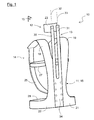
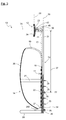
- the muscle exercise apparatus 10 comprises a back support structure 11, a cranial support structure 12, a connecting structure 13, and a suspension and holding structure 14.
- This device is particularly adapted to provide controlled resistance to the forces exerted by a user wearing the device and making movements of the head relative to the trunk, from front to back and / or vice versa.
- the exercise apparatus 10 as well as each of the structures 11 to 14, has general symmetry along a median anteroposterior plane which is the plane of the figure 3 .
- the back support structure 11 comprises a back support member 16 - or backrest - which extends along a back support plane 17 which is substantially vertical when a user in a standing position carries the device 10 .
- the piece 16 is in the form of a thin plate whose contour, in front view or rear, has a curved central portion, an upper portion flared upwardly, and a lower portion flared downwardly.
- the upper part of the part 16 is extended by two curved blades 18, 19 forming two portions - or primers - of straps forming part of the suspension structure 14 of the device to the user.
- the lower part of the piece 16 is also extended by two curved blades 20, 21 forming two portions - or primers - abdominal strap, which are part of the structure 14 holding the device against the back of the user.
- the blades 18 to 21 extend forward of the transverse plane 17 of dorsal support.
- the piece 16 and the blades 18 to 21 extending the piece 16 may form a single piece which may be made of composite material, for example resin filled with carbon reinforcing fibers, so as to form a light, rigid structure, and of which the ergonomic shape is simple to manufacture.
- the part 16 and the blades 18 to 21 may be coated, on their inner face, with a quilted coating such as the coating 22 of the front face of the illustrated part 16 figure 3 .
- the suspension structure 14 further comprises two straps 25, 26, which are respectively fixed to the ends of the blades 18, 19 which they extend to form two shoulder straps whose lower ends (such as the one marked 260 figure 3 ) can be respectively fixed to the blades 20, 21.
- Each of these straps 25, 26 may comprise, in its upper part, a handle (not shown)
- the handles fitted to these straps can be grasped by the user practicing an exercise so as to be arranged substantially at the level of the clavicles of the user, in a grouped position of the upper body. This makes it possible to intimately connect the device to the user, to concentrate the muscular effort at the level of the cervical vertebrae, and to prevent the user from adopting a bad working posture.
- the structure 14 for holding the device against the back of the user comprises a thoracic strap 27 extending substantially horizontally and perpendicular to the shoulder straps, and whose two ends are fixed to the back support structure 11, in particular to the room 16.
- the holding structure 14 also comprises a strap 28 abdominal, also extending substantially horizontally, under the thoracic strap, and extending the primer 20, 21 webbing integral with - or integrated with - the back support part 16.
- the straps and straps 25 to 28 are for example made of a synthetic textile material and provided with members for adjusting their "useful" length.
- the suspension and holding structure 14, which is thus fixed to the back support structure 11, makes it possible to suspend the device at the shoulders of the user and to maintain the back support structure resting against the back of the patient. by tightening (shortening) these straps and straps.
- the cranial support structure 12 comprises a cranial support piece 23 - or headrest - which extends along a cranial support plane 29 which is substantially vertical and parallel to the back support plane 17, when a user carries the apparatus 10 without exerting force on the cranial support structure 12.
- the cranial support structure 12 is supported by the connecting structure 13 connecting the back support structure to the cranial support structure, and having an adjustable stiffness.
- the inner face - or front face - of the part 23 may be covered with a padded coating 24 ( figure 3 ), especially when the part 23 is made of a rigid material such as a composite material comprising carbon reinforcing fibers.
- the part 23, the coating 24, and the structure 12 may be in the form of thin cylindrical caps whose concavity is directed towards the front.
- the connecting structure 13 comprises two substantially planar and rectilinear blades 30, 31, respectively extending along two substantially parallel axes 32, 33, on either side of the median anteroposterior plane of the apparatus, substantially parallel to the plane 17 back support and cranial support plane 29.
- the blades 30, 31 are substantially coplanar and mutually integral by their respective lower parts which form a flat plate 34 through which the blades 30, 31 are secured to the part 16 of the back support structure by bolts 35, 36 ( figure 3 ).
- Each bolt comprises a threaded rod 35, one end of which is rigidly fixed - embedded or otherwise anchored or embedded - in the back support member 16, each rod 35 extending through an orifice provided in the plate 34, opening - and protruding - on the back side of this plate.
- Each bolt for fixing the blades 30, 31 to the structure 11 further comprises a nut 36 designed to be screwed onto the free end ("open") of one of the threaded rods 35, and to be placed on the face rear of the plate 34, so as to clamp the plate 34 against the rear face of the part 16.
- the apparatus comprises six rods 35 regularly spaced vertically (along the axes 32, 33), only two of which are equipped with a nut 36 clamping.
- the blades 30, 31 can be joined substantially over their entire length, thus forming a plate 34 extending up to the axis 38 - and where appropriate above the axis 38 - transmission of the forces exerted by the user on the headrest, this headrest to the structure 13 connecting, the axis 38 being substantially horizontal when the device is in use by a user in a standing position .
- the cranial support structure 12 is suspended at the upper part of the blades 30, 31 and the adjustable stiffness connecting structure 13, via a workpiece 40 of force transmission, and a hinge 39.
- the piece 40 of force transmission which is in the form of jumper or "U" is secured to the rear face of the piece 23, as well as the hinge 39 which is integral with the front face of the blades 30, 31.
- the part 40 comprises a sensor (mark 43) of force - or force - responsive to the deformation of the part 40 along the axis of effort 38, i.e. the "pinching" of the piece 40, in particular a strain gauge sensor (s) integral with - or integrated with - a wing of the piece 40, for example integral with the central wing of this piece 40.
- a sensor mark 43 of force - or force - responsive to the deformation of the part 40 along the axis of effort 38, i.e. the "pinching" of the piece 40
- a strain gauge sensor s integral with - or integrated with - a wing of the piece 40, for example integral with the central wing of this piece 40.
- This force sensor is thus sensitive to the forces exerted by the user on the cranial support structure 12, and transmitted to the connecting structure 13 by the cranial support structure.
- the apparatus 10 further comprises means for transmitting signals - or data - of effort, which are connected to this force measuring sensor 43 for transmitting the signals - or data - of effort delivered by this sensor and for present them to the user or to a third party, if necessary after treatment.
- the signal transmission means - or data - effort may comprise a cable (not shown) connecting the force measurement sensor to a housing (not shown) containing an electronic unit for processing signals - or data - d effort, this unit comprising means for displaying and / or recording data delivered by the force measurement sensor.
- the hinge 39 allows an articulation of the cranial support structure 12 with respect to the adjustable stiffness connecting structure 13, in particular a rotation of the cranial support structure 12 with respect to the linkage structure 13 along an axis 41 articulation which is substantially perpendicular to the longitudinal axes 32, 33 of the blades 30, 31 of the structure 13 connecting.
- This axis 41 of articulation - of rotation - extends generally substantially horizontally when the apparatus is in use by a user in a standing position, and in a transverse plane parallel to the support planes 17, 29.
- the articulation - or patella - 39 has an elastic deformation capacity to recall the cranial support structure 12 to a rest position in which the planes 17, 29 are substantially parallel, when no effort is exerted on this user structure.
- the hinge 39 which connects the blades 30, 31 of the connecting structure 13 to the force transmission part 40 equipped with the force sensor, can be made of an elastomeric material.
- the apparatus 10 comprises a source 42 of light integral with the cranial support structure 12, emitting a light beam directed towards the front, substantially perpendicularly to the cranial support plane 29, to form a first pattern allowing a visual control of the inclination of the structure 12 along the articulation axis 41.
- the user of the exercise apparatus may carry a second light source, which may be secured to his head by a headband around the wearer's head, emitting a second light beam directed forward to form a second sight for visual control of the inclination of its head along the hinge axis 41.
- Such a band can be connected (e) to the cranial support part 23 and can be arranged (e) to form a front support piece for the user, so as to transmit to the measuring means of effort exerted by the user on this headband, during movements of the head from the back to the front.
- the apparatus 10 may comprise two hinges 39 respectively integral with the two blades 30, 31 and integral with a junction piece joining these joints to the piece 40 transmission and force measurement.
Landscapes
- Health & Medical Sciences (AREA)
- General Health & Medical Sciences (AREA)
- Physical Education & Sports Medicine (AREA)
- Life Sciences & Earth Sciences (AREA)
- Biophysics (AREA)
- Orthopedic Medicine & Surgery (AREA)
- Otolaryngology (AREA)
- Pulmonology (AREA)
- Rehabilitation Tools (AREA)
Claims (16)
- Trainingsgerät (10), eine Rückenanlagestruktur (11) umfassend, eineKopfanlagestruktur (12) und eine Aufhänge- und Haltestruktur(14), die mit der Rückenanlagestruktur verbunden und dafür eingerichtet ist, das Gerät über die Schultern eines Benutzers zu hängen, sowie dafür, die Rückenanlagestruktur an den Rücken des Benutzers anliegend zu halten, dadurch gekennzeichnet, dass es außerdem umfasst:eine Verbindungsstruktur (13), die die Rückenanlagestruktur mit der Kopfanlagestruktur verbindet und eine einstellbare Steifheit aufweist,- Kraftmessmittel (40, 43), die auf die Kräfte empfindlich sind, die der Benutzer auf die Kopfanlagestruktur ausübt, die auf die Kräfte empfindlich sind, die von der Kopfanlagestruktur (12) auf die Verbindungsstruktur (13) übertragen werden, die einen Kraftsensor (43) umfassen, der zwischen der Verbindungsstruktur (13) und der Kopfanlagestruktur (12) angeordnet ist, und- Mittel zur Übertragung von Kraftsignalen - oder Kraftdaten -, die mit den Kraftmessmitteln verbunden sind und dafür eingerichtet sind, die Kraftsignale - oder Kraftdaten - zu übertragen, die von diesen Kraftmessmitteln ausgegeben werden.
- Gerät nach Patentanspruch 1, in dem der Kraftsensor ein Dehnungsmesssensor (43) ist, der mit einem Kraftübertragungsteil (40) verbunden ist, das die Verbindungsstruktur (13) mit der Kopfanlagestruktur (12) verbindet.
- Gerät nach Patentanspruch 1 oder 2, in dem die Mittel zur Übertragung von Kraftsignalen - oder Kraftdaten - die Kraftmessmittel mit einer Kraftsignal- - oder Kraftdaten- - -verarbeitungseinheit verbinden, die Anzeige- und/oder Speichermittel für die Daten, die von den Kraftmessmitteln oder der Verarbeitungseinheit ausgegeben werden, aufweist - oder damit verbunden ist.
- Gerät nach irgendeinem der Patentansprüche 1 bis 3, in dem die Kraftsignalübertragung - oder Kraftdatenübertragung - eine Übertragung über Kabel oder eine drahtlose Übertragung ist, beispielsweise eine optische oder eine Funkwellenübertragung.
- Gerät nach irgendeinem der Patentansprüche 1 bis 4, in dem sich die Verbindungsstruktur (13) mit einstellbarer Steifheit längs mindestens einer Längsachse (32, 33) erstreckt, wobei sich die Rückenanlagestruktur (11) längs einer Rückenanlageebene (17) erstreckt, die im Wesentlichen zu dieser/n Längsachse/n (32, 33) parallel verläuft und wobei diese Ebene (17) im Wesentlichen vertikal ist, wenn das Gerät von einem aufrecht stehenden Benutzer verwendet wird.
- Gerät nach irgendeinem der Patentansprüche 1 bis 5, das Gelenkmittel (39) umfasst, die eine gelenkige Verbindung der Kopfanlagestruktur (12) gegenüber der Verbindungsstruktur (13) mit einstellbarer Steifheit erlaubt, insbesondere eine Anlenkung - d.h. eine Drehung - der Kopfanlagestruktur relativ zur Verbindungsstruktur um eine zur Längsachse (32, 33) der Verbindungsstruktur einstellbarer Steifheit rechtwinklige und zur Ebene (17), längs derer die Rückenanlagestruktur (11) verläuft, parallele Gelenkachse (41).
- Gerät nach Patentanspruch 6, in dem die Gelenkachse (41) - die Drehachse- im Wesentlichen horizontal verläuft, während das Gerät von einem aufrecht stehendenBenutzer verwendet wird, und in Querrichtung.
- Gerät nach Patentanspruch 6 oder 7, in dem die Gelenkmittel (39) über ein elastisches Verformungsvermögen verfügen, das die Rückkehr der Kopfanlagestruktur (12) in eine Ruhestellung sicherstellt, wenn vom Benutzer auf dieseStrukturkeine Kraft ausgeübt wird.
- Gerät nach irgendeinem der Patentansprüche 6 bis 8, in dem die Gelenkmittel ein Gelenk - oder Kugelgelenk - aufweisen und/oder im Wesentlichen daraus bestehen, das aus einem Elastomermaterial besteht und das zwischen die Kopfanlagestruktur (12) und die Verbindungsstruktur (13) einstellbarer Steifheit eingefügt ist, insbesondere zwischen einem Kraftübertragungsstück (40), das mit einem Kraftsensor (43) versehen ist, und dieser Verbindungsstruktur (13).
- Gerät nach irgendeinem der Patentansprüche 1 bis 9, in dem die Kopfanlagestruktur(12) eine schiefe Form hat, deren Konkavität vorwärts weist, und die in Ruhestellung längs einer Kopfanlageebene (29) verläuft, die zur Ebene (17) im Wesentlichen parallel ist, längs derer sich die Rückenanlagestruktur (11) erstreckt.
- Gerät nach irgendeinem der Patentansprüche 1 bis 10, das eine Lichtquelle (42) umfasst, die mit der Kopfanlagestruktur (12) fest verbunden ist und derart eingerichtet ist, dass sie einen Lichtstrahl nach vorne sendet, im Wesentlichen senkrecht zur Ebene (29), längs derer die Kopfanlagestruktur (12) verläuft, um dem das Gerät (10) tragenden Benutzer, der einen Lichtfleck beobachtet, der durch die Reflektion des Lichtstrahls an einem vor dem Benutzer angeordneten Gegenstand, der ein Ziel darstellt, entsteht, zu erlauben, die Neigung der Kopfanlagestruktur um eine Gelenkachse (41)der Kopfanlagestruktur (12) visuell zu kontrollieren.
- Gerät nach irgendeinem der Patentansprüche 1 bis 11, in dem die Verbindungsstruktur (13) mit einstellbarer Steifheit zwei im Wesentlichen parallele Klingen (30, 31) umfasst, die sich beiderseits der anteroposterioren Mittelebene (15) des Gerätes (10) erstrecken,, derart, dass die Bewegungsfreiheit der Kopfanlagestruktur (12), insbesondere die Drehbarkeit dieserStruktur (12) um eine zur Längsachse (32, 33) der Verbindungsstruktur (13) parallele Achse, eingeschränkt ist.
- Gerät nach irgendeinem der Patentansprüche 1 bis 12,das zwei Gelenke (39) aufweist, die jeweils mit einer von zwei Klingen (30, 31) der Verbindungsstruktur (13) fest verbunden sind, unddie mit einem Verbindungsstück fest verbunden sind, sowie ein Kraftübertragungs- und -messstück (40), das dieses Verbindungsstück mit der Kopfanlagestruktur (12) verbindet.
- Gerät nach Patentanspruch 13, in dem die beiden Klingen (30, 31) in ihrem jeweiligen unteren Bereich miteinander fest verbunden sind, über den die Klingen mit der Rückenanlagestruktur(11) durch Verbindungsmittel (35, 36) - wie etwa Bolzen - fest verbunden sind, die erlauben, die Länge (37) des "fliegend gelagerten" oberen Teils dieser Klingen einzustellen und damit die Steifheit der Verbindungsstruktur.
- Gerät nach irgendeinem der Patentansprüche 1 bis 14, in dem dieAufhänge- und Haltestruktur (14) zwei Gurte (25, 26) umfasst, die jeweils mit einem Griff versehen sind, einen Brustriemen (27) und einen Bauchriemen (28), die mit der Rückenanlagestruktur(11) fest verbunden sind.
- Gerät nach irgendeinem der Patentansprüche 1 bis 15, das eine Stirnanlagestruktur aufweist, die mit der Kopfanlagestruktur fest verbunden ist, insbesondere ein/en Stirnanlageriemen oder -band, um Kräfte, die vom Benutzer bei Bewegungen des Kopfes von hinten nach vorne auf diese Struktur ausgeübt werden, auf die Kraftmessmittel zu übertragen.
Applications Claiming Priority (1)
| Application Number | Priority Date | Filing Date | Title |
|---|---|---|---|
| FR1301120A FR3005582B1 (fr) | 2013-05-15 | 2013-05-15 | Appareil d'exercice pour la musculation des zones cervicales |
Publications (2)
| Publication Number | Publication Date |
|---|---|
| EP2803390A1 EP2803390A1 (de) | 2014-11-19 |
| EP2803390B1 true EP2803390B1 (de) | 2016-09-28 |
Family
ID=48856708
Family Applications (1)
| Application Number | Title | Priority Date | Filing Date |
|---|---|---|---|
| EP14358001.7A Not-in-force EP2803390B1 (de) | 2013-05-15 | 2014-05-15 | Übungsgerät zur Muskelstärkung im Nackenbereich (zervikale Zonen) |
Country Status (2)
| Country | Link |
|---|---|
| EP (1) | EP2803390B1 (de) |
| FR (1) | FR3005582B1 (de) |
Families Citing this family (3)
| Publication number | Priority date | Publication date | Assignee | Title |
|---|---|---|---|---|
| NO340488B1 (en) | 2015-09-22 | 2017-05-02 | Neckfocus As | Neck Training Apparatus |
| NO343282B1 (en) | 2016-10-27 | 2019-01-14 | Frebra Holding As | Neckbalance |
| NO342657B1 (en) | 2016-10-27 | 2018-06-25 | Frebra Holding As | Neckpillow |
Family Cites Families (7)
| Publication number | Priority date | Publication date | Assignee | Title |
|---|---|---|---|---|
| DE2536560C3 (de) * | 1975-08-16 | 1978-06-29 | Peter Dr.Med. 6101 Nieder- Ramstadt Will | Trainingsgerät |
| US4066259A (en) * | 1976-05-13 | 1978-01-03 | Brentham Jerry D | Neck exerciser |
| US5248293A (en) * | 1991-10-29 | 1993-09-28 | Biomechanical Design, Inc. | Tethered medical restraint device |
| US5336139A (en) * | 1993-03-11 | 1994-08-09 | Miller Bruce W | Isotonic cervical exercise device |
| US7153246B2 (en) * | 2001-11-13 | 2006-12-26 | Richard Koscielny | Neurological motor therapy suit |
| FR2883760B1 (fr) | 2005-03-30 | 2012-08-31 | Patrice Blanc | Appareil pour la musculation des zones cervicales |
| US20100292051A1 (en) * | 2009-05-12 | 2010-11-18 | Neckrx, Inc. | User operable neck isometric and isokinetic exercise device and method |
-
2013
- 2013-05-15 FR FR1301120A patent/FR3005582B1/fr not_active Expired - Fee Related
-
2014
- 2014-05-15 EP EP14358001.7A patent/EP2803390B1/de not_active Not-in-force
Non-Patent Citations (1)
| Title |
|---|
| None * |
Also Published As
| Publication number | Publication date |
|---|---|
| FR3005582A1 (fr) | 2014-11-21 |
| FR3005582B1 (fr) | 2015-05-29 |
| EP2803390A1 (de) | 2014-11-19 |
Similar Documents
| Publication | Publication Date | Title |
|---|---|---|
| CA1266408A (fr) | Appareil de detection et de correction d'anomalies d'equilibre du corps humain | |
| CA2739233C (fr) | Dispositif de mobilisation corporelle et utilisation d'un tel dispositif | |
| EP0389379B1 (de) | Orthese zur dreidimensionalen dynamischen Rückbildung einer Skoliose | |
| EP2803390A1 (de) | Übungsgerät zur Muskelstärkung im Nackenbereich (zervikale Zonen) | |
| US10130281B2 (en) | Device for measuring bioimpedances | |
| EP2768440B1 (de) | Unteres exoskelett | |
| US8864694B2 (en) | Brace | |
| TWI377935B (en) | Orthopedic technical auxilliary means | |
| EP2621340A1 (de) | Vorrichtung für muskelkräftigung und/oder -rehabilitation des schultergelenks und der oberen extremitäten in geschlossener bewegungskette | |
| US10610383B2 (en) | Prosthetic knee joint for an above-the-knee amputee | |
| EP1747764A3 (de) | Tragevorrichtung für einen Monitor zur Verwendung in einer diagnostischen Ultraschallvorrichtung | |
| SE455567B (sv) | Anordning for detektering av legesforendringar kring en led, spec ryggraden | |
| KR20190021020A (ko) | 인체 근육의 장력측정 장치 | |
| FR3092029A1 (fr) | Harnais de posture d’un exosquelette | |
| FR3031664A1 (fr) | Ergometre pour cheville | |
| BE1003497A5 (fr) | Outil a main. | |
| JP5528728B2 (ja) | 歩行系統の筋肉を増強するためのトレーニング装置 | |
| WO2019211532A2 (fr) | Ceinture de report de charges adaptée à porter au moins un accessoire d'un exosquelette passif | |
| EP1515623B1 (de) | Stiefel mit schwebender verbindung | |
| FR2863482A1 (fr) | Element de connexion multi-composants, reglable et demontable et orthese contenant un tel element | |
| FR2883760A1 (fr) | Appareil pour la musculation des zones cervicales | |
| FR2877834A1 (fr) | Appareil orthopedique de correction du pied-bot | |
| FR3057484A1 (fr) | Dispositif portable de support de charge eloignee de la personne qui la porte | |
| FR3108030A1 (fr) | Harnais de posture | |
| FR3110389A1 (fr) | Structure déformable d’aide au mouvement d’articulation et procédé correspondant |
Legal Events
| Date | Code | Title | Description |
|---|---|---|---|
| PUAI | Public reference made under article 153(3) epc to a published international application that has entered the european phase |
Free format text: ORIGINAL CODE: 0009012 |
|
| 17P | Request for examination filed |
Effective date: 20140515 |
|
| AK | Designated contracting states |
Kind code of ref document: A1 Designated state(s): AL AT BE BG CH CY CZ DE DK EE ES FI FR GB GR HR HU IE IS IT LI LT LU LV MC MK MT NL NO PL PT RO RS SE SI SK SM TR |
|
| AX | Request for extension of the european patent |
Extension state: BA ME |
|
| R17P | Request for examination filed (corrected) |
Effective date: 20150519 |
|
| RBV | Designated contracting states (corrected) |
Designated state(s): AL AT BE BG CH CY CZ DE DK EE ES FI FR GB GR HR HU IE IS IT LI LT LU LV MC MK MT NL NO PL PT RO RS SE SI SK SM TR |
|
| RIC1 | Information provided on ipc code assigned before grant |
Ipc: A63B 23/025 20060101ALI20150721BHEP Ipc: A63B 21/00 20060101ALI20150721BHEP Ipc: A63B 21/02 20060101AFI20150721BHEP Ipc: A63B 21/04 20060101ALI20150721BHEP Ipc: A63B 71/06 20060101ALI20150721BHEP Ipc: A63B 24/00 20060101ALI20150721BHEP |
|
| 17Q | First examination report despatched |
Effective date: 20150908 |
|
| GRAP | Despatch of communication of intention to grant a patent |
Free format text: ORIGINAL CODE: EPIDOSNIGR1 |
|
| INTG | Intention to grant announced |
Effective date: 20160210 |
|
| GRAP | Despatch of communication of intention to grant a patent |
Free format text: ORIGINAL CODE: EPIDOSNIGR1 |
|
| RAP1 | Party data changed (applicant data changed or rights of an application transferred) |
Owner name: BLANC, PATRICE Owner name: LICOT, OLIVIER Owner name: ORTHOPEDIE BONTOUX G.A. |
|
| GRAS | Grant fee paid |
Free format text: ORIGINAL CODE: EPIDOSNIGR3 |
|
| GRAA | (expected) grant |
Free format text: ORIGINAL CODE: 0009210 |
|
| INTC | Intention to grant announced (deleted) | ||
| INTG | Intention to grant announced |
Effective date: 20160809 |
|
| AK | Designated contracting states |
Kind code of ref document: B1 Designated state(s): AL AT BE BG CH CY CZ DE DK EE ES FI FR GB GR HR HU IE IS IT LI LT LU LV MC MK MT NL NO PL PT RO RS SE SI SK SM TR |
|
| REG | Reference to a national code |
Ref country code: GB Ref legal event code: FG4D Free format text: NOT ENGLISH |
|
| REG | Reference to a national code |
Ref country code: CH Ref legal event code: EP |
|
| REG | Reference to a national code |
Ref country code: AT Ref legal event code: REF Ref document number: 832240 Country of ref document: AT Kind code of ref document: T Effective date: 20161015 |
|
| REG | Reference to a national code |
Ref country code: IE Ref legal event code: FG4D Free format text: LANGUAGE OF EP DOCUMENT: FRENCH |
|
| REG | Reference to a national code |
Ref country code: DE Ref legal event code: R096 Ref document number: 602014003982 Country of ref document: DE |
|
| REG | Reference to a national code |
Ref country code: LT Ref legal event code: MG4D |
|
| PG25 | Lapsed in a contracting state [announced via postgrant information from national office to epo] |
Ref country code: FI Free format text: LAPSE BECAUSE OF FAILURE TO SUBMIT A TRANSLATION OF THE DESCRIPTION OR TO PAY THE FEE WITHIN THE PRESCRIBED TIME-LIMIT Effective date: 20160928 Ref country code: HR Free format text: LAPSE BECAUSE OF FAILURE TO SUBMIT A TRANSLATION OF THE DESCRIPTION OR TO PAY THE FEE WITHIN THE PRESCRIBED TIME-LIMIT Effective date: 20160928 Ref country code: RS Free format text: LAPSE BECAUSE OF FAILURE TO SUBMIT A TRANSLATION OF THE DESCRIPTION OR TO PAY THE FEE WITHIN THE PRESCRIBED TIME-LIMIT Effective date: 20160928 Ref country code: LT Free format text: LAPSE BECAUSE OF FAILURE TO SUBMIT A TRANSLATION OF THE DESCRIPTION OR TO PAY THE FEE WITHIN THE PRESCRIBED TIME-LIMIT Effective date: 20160928 Ref country code: NO Free format text: LAPSE BECAUSE OF FAILURE TO SUBMIT A TRANSLATION OF THE DESCRIPTION OR TO PAY THE FEE WITHIN THE PRESCRIBED TIME-LIMIT Effective date: 20161228 |
|
| REG | Reference to a national code |
Ref country code: NL Ref legal event code: MP Effective date: 20160928 |
|
| REG | Reference to a national code |
Ref country code: AT Ref legal event code: MK05 Ref document number: 832240 Country of ref document: AT Kind code of ref document: T Effective date: 20160928 |
|
| PG25 | Lapsed in a contracting state [announced via postgrant information from national office to epo] |
Ref country code: SE Free format text: LAPSE BECAUSE OF FAILURE TO SUBMIT A TRANSLATION OF THE DESCRIPTION OR TO PAY THE FEE WITHIN THE PRESCRIBED TIME-LIMIT Effective date: 20160928 Ref country code: GR Free format text: LAPSE BECAUSE OF FAILURE TO SUBMIT A TRANSLATION OF THE DESCRIPTION OR TO PAY THE FEE WITHIN THE PRESCRIBED TIME-LIMIT Effective date: 20161229 Ref country code: LV Free format text: LAPSE BECAUSE OF FAILURE TO SUBMIT A TRANSLATION OF THE DESCRIPTION OR TO PAY THE FEE WITHIN THE PRESCRIBED TIME-LIMIT Effective date: 20160928 Ref country code: NL Free format text: LAPSE BECAUSE OF FAILURE TO SUBMIT A TRANSLATION OF THE DESCRIPTION OR TO PAY THE FEE WITHIN THE PRESCRIBED TIME-LIMIT Effective date: 20160928 |
|
| PG25 | Lapsed in a contracting state [announced via postgrant information from national office to epo] |
Ref country code: RO Free format text: LAPSE BECAUSE OF FAILURE TO SUBMIT A TRANSLATION OF THE DESCRIPTION OR TO PAY THE FEE WITHIN THE PRESCRIBED TIME-LIMIT Effective date: 20160928 Ref country code: EE Free format text: LAPSE BECAUSE OF FAILURE TO SUBMIT A TRANSLATION OF THE DESCRIPTION OR TO PAY THE FEE WITHIN THE PRESCRIBED TIME-LIMIT Effective date: 20160928 |
|
| REG | Reference to a national code |
Ref country code: FR Ref legal event code: PLFP Year of fee payment: 4 |
|
| PG25 | Lapsed in a contracting state [announced via postgrant information from national office to epo] |
Ref country code: ES Free format text: LAPSE BECAUSE OF FAILURE TO SUBMIT A TRANSLATION OF THE DESCRIPTION OR TO PAY THE FEE WITHIN THE PRESCRIBED TIME-LIMIT Effective date: 20160928 Ref country code: PT Free format text: LAPSE BECAUSE OF FAILURE TO SUBMIT A TRANSLATION OF THE DESCRIPTION OR TO PAY THE FEE WITHIN THE PRESCRIBED TIME-LIMIT Effective date: 20170130 Ref country code: IS Free format text: LAPSE BECAUSE OF FAILURE TO SUBMIT A TRANSLATION OF THE DESCRIPTION OR TO PAY THE FEE WITHIN THE PRESCRIBED TIME-LIMIT Effective date: 20170128 Ref country code: SK Free format text: LAPSE BECAUSE OF FAILURE TO SUBMIT A TRANSLATION OF THE DESCRIPTION OR TO PAY THE FEE WITHIN THE PRESCRIBED TIME-LIMIT Effective date: 20160928 Ref country code: SM Free format text: LAPSE BECAUSE OF FAILURE TO SUBMIT A TRANSLATION OF THE DESCRIPTION OR TO PAY THE FEE WITHIN THE PRESCRIBED TIME-LIMIT Effective date: 20160928 Ref country code: CZ Free format text: LAPSE BECAUSE OF FAILURE TO SUBMIT A TRANSLATION OF THE DESCRIPTION OR TO PAY THE FEE WITHIN THE PRESCRIBED TIME-LIMIT Effective date: 20160928 Ref country code: BG Free format text: LAPSE BECAUSE OF FAILURE TO SUBMIT A TRANSLATION OF THE DESCRIPTION OR TO PAY THE FEE WITHIN THE PRESCRIBED TIME-LIMIT Effective date: 20161228 Ref country code: PL Free format text: LAPSE BECAUSE OF FAILURE TO SUBMIT A TRANSLATION OF THE DESCRIPTION OR TO PAY THE FEE WITHIN THE PRESCRIBED TIME-LIMIT Effective date: 20160928 Ref country code: AT Free format text: LAPSE BECAUSE OF FAILURE TO SUBMIT A TRANSLATION OF THE DESCRIPTION OR TO PAY THE FEE WITHIN THE PRESCRIBED TIME-LIMIT Effective date: 20160928 |
|
| REG | Reference to a national code |
Ref country code: DE Ref legal event code: R097 Ref document number: 602014003982 Country of ref document: DE |
|
| PG25 | Lapsed in a contracting state [announced via postgrant information from national office to epo] |
Ref country code: IT Free format text: LAPSE BECAUSE OF FAILURE TO SUBMIT A TRANSLATION OF THE DESCRIPTION OR TO PAY THE FEE WITHIN THE PRESCRIBED TIME-LIMIT Effective date: 20160928 |
|
| PG25 | Lapsed in a contracting state [announced via postgrant information from national office to epo] |
Ref country code: DK Free format text: LAPSE BECAUSE OF FAILURE TO SUBMIT A TRANSLATION OF THE DESCRIPTION OR TO PAY THE FEE WITHIN THE PRESCRIBED TIME-LIMIT Effective date: 20160928 |
|
| PLBE | No opposition filed within time limit |
Free format text: ORIGINAL CODE: 0009261 |
|
| STAA | Information on the status of an ep patent application or granted ep patent |
Free format text: STATUS: NO OPPOSITION FILED WITHIN TIME LIMIT |
|
| PG25 | Lapsed in a contracting state [announced via postgrant information from national office to epo] |
Ref country code: LU Free format text: LAPSE BECAUSE OF NON-PAYMENT OF DUE FEES Effective date: 20170531 |
|
| 26N | No opposition filed |
Effective date: 20170629 |
|
| PG25 | Lapsed in a contracting state [announced via postgrant information from national office to epo] |
Ref country code: SI Free format text: LAPSE BECAUSE OF FAILURE TO SUBMIT A TRANSLATION OF THE DESCRIPTION OR TO PAY THE FEE WITHIN THE PRESCRIBED TIME-LIMIT Effective date: 20160928 |
|
| REG | Reference to a national code |
Ref country code: CH Ref legal event code: PL |
|
| PG25 | Lapsed in a contracting state [announced via postgrant information from national office to epo] |
Ref country code: MC Free format text: LAPSE BECAUSE OF FAILURE TO SUBMIT A TRANSLATION OF THE DESCRIPTION OR TO PAY THE FEE WITHIN THE PRESCRIBED TIME-LIMIT Effective date: 20160928 |
|
| REG | Reference to a national code |
Ref country code: IE Ref legal event code: MM4A |
|
| PG25 | Lapsed in a contracting state [announced via postgrant information from national office to epo] |
Ref country code: LI Free format text: LAPSE BECAUSE OF NON-PAYMENT OF DUE FEES Effective date: 20170531 Ref country code: CH Free format text: LAPSE BECAUSE OF NON-PAYMENT OF DUE FEES Effective date: 20170531 |
|
| PG25 | Lapsed in a contracting state [announced via postgrant information from national office to epo] |
Ref country code: LU Free format text: LAPSE BECAUSE OF NON-PAYMENT OF DUE FEES Effective date: 20170515 |
|
| PG25 | Lapsed in a contracting state [announced via postgrant information from national office to epo] |
Ref country code: IE Free format text: LAPSE BECAUSE OF NON-PAYMENT OF DUE FEES Effective date: 20170515 |
|
| REG | Reference to a national code |
Ref country code: FR Ref legal event code: PLFP Year of fee payment: 5 |
|
| PGFP | Annual fee paid to national office [announced via postgrant information from national office to epo] |
Ref country code: DE Payment date: 20180524 Year of fee payment: 5 |
|
| PGFP | Annual fee paid to national office [announced via postgrant information from national office to epo] |
Ref country code: TR Payment date: 20180418 Year of fee payment: 8 |
|
| PG25 | Lapsed in a contracting state [announced via postgrant information from national office to epo] |
Ref country code: MT Free format text: LAPSE BECAUSE OF FAILURE TO SUBMIT A TRANSLATION OF THE DESCRIPTION OR TO PAY THE FEE WITHIN THE PRESCRIBED TIME-LIMIT Effective date: 20160928 |
|
| PG25 | Lapsed in a contracting state [announced via postgrant information from national office to epo] |
Ref country code: AL Free format text: LAPSE BECAUSE OF FAILURE TO SUBMIT A TRANSLATION OF THE DESCRIPTION OR TO PAY THE FEE WITHIN THE PRESCRIBED TIME-LIMIT Effective date: 20160928 |
|
| PGFP | Annual fee paid to national office [announced via postgrant information from national office to epo] |
Ref country code: GB Payment date: 20180523 Year of fee payment: 5 |
|
| PG25 | Lapsed in a contracting state [announced via postgrant information from national office to epo] |
Ref country code: HU Free format text: LAPSE BECAUSE OF FAILURE TO SUBMIT A TRANSLATION OF THE DESCRIPTION OR TO PAY THE FEE WITHIN THE PRESCRIBED TIME-LIMIT; INVALID AB INITIO Effective date: 20140515 |
|
| PG25 | Lapsed in a contracting state [announced via postgrant information from national office to epo] |
Ref country code: CY Free format text: LAPSE BECAUSE OF FAILURE TO SUBMIT A TRANSLATION OF THE DESCRIPTION OR TO PAY THE FEE WITHIN THE PRESCRIBED TIME-LIMIT Effective date: 20160928 |
|
| PG25 | Lapsed in a contracting state [announced via postgrant information from national office to epo] |
Ref country code: MK Free format text: LAPSE BECAUSE OF FAILURE TO SUBMIT A TRANSLATION OF THE DESCRIPTION OR TO PAY THE FEE WITHIN THE PRESCRIBED TIME-LIMIT Effective date: 20160928 |
|
| REG | Reference to a national code |
Ref country code: DE Ref legal event code: R119 Ref document number: 602014003982 Country of ref document: DE |
|
| GBPC | Gb: european patent ceased through non-payment of renewal fee |
Effective date: 20190515 |
|
| REG | Reference to a national code |
Ref country code: BE Ref legal event code: MM Effective date: 20190531 |
|
| PG25 | Lapsed in a contracting state [announced via postgrant information from national office to epo] |
Ref country code: TR Free format text: LAPSE BECAUSE OF FAILURE TO SUBMIT A TRANSLATION OF THE DESCRIPTION OR TO PAY THE FEE WITHIN THE PRESCRIBED TIME-LIMIT Effective date: 20160928 |
|
| PG25 | Lapsed in a contracting state [announced via postgrant information from national office to epo] |
Ref country code: DE Free format text: LAPSE BECAUSE OF NON-PAYMENT OF DUE FEES Effective date: 20191203 Ref country code: GB Free format text: LAPSE BECAUSE OF NON-PAYMENT OF DUE FEES Effective date: 20190515 |
|
| PG25 | Lapsed in a contracting state [announced via postgrant information from national office to epo] |
Ref country code: BE Free format text: LAPSE BECAUSE OF NON-PAYMENT OF DUE FEES Effective date: 20190531 |
|
| PGFP | Annual fee paid to national office [announced via postgrant information from national office to epo] |
Ref country code: FR Payment date: 20210518 Year of fee payment: 8 |
|
| PG25 | Lapsed in a contracting state [announced via postgrant information from national office to epo] |
Ref country code: FR Free format text: LAPSE BECAUSE OF NON-PAYMENT OF DUE FEES Effective date: 20220531 |