EP2802844B1 - Sensorsystem für ein gargerät - Google Patents
Sensorsystem für ein gargerät Download PDFInfo
- Publication number
- EP2802844B1 EP2802844B1 EP12813846.8A EP12813846A EP2802844B1 EP 2802844 B1 EP2802844 B1 EP 2802844B1 EP 12813846 A EP12813846 A EP 12813846A EP 2802844 B1 EP2802844 B1 EP 2802844B1
- Authority
- EP
- European Patent Office
- Prior art keywords
- sensor
- unit
- calibration
- cooking utensil
- utensil according
- Prior art date
- Legal status (The legal status is an assumption and is not a legal conclusion. Google has not performed a legal analysis and makes no representation as to the accuracy of the status listed.)
- Active
Links
Images
Classifications
-
- G—PHYSICS
- G01—MEASURING; TESTING
- G01D—MEASURING NOT SPECIALLY ADAPTED FOR A SPECIFIC VARIABLE; ARRANGEMENTS FOR MEASURING TWO OR MORE VARIABLES NOT COVERED IN A SINGLE OTHER SUBCLASS; TARIFF METERING APPARATUS; MEASURING OR TESTING NOT OTHERWISE PROVIDED FOR
- G01D3/00—Indicating or recording apparatus with provision for the special purposes referred to in the subgroups
- G01D3/08—Indicating or recording apparatus with provision for the special purposes referred to in the subgroups with provision for safeguarding the apparatus, e.g. against abnormal operation, against breakdown
-
- G—PHYSICS
- G01—MEASURING; TESTING
- G01D—MEASURING NOT SPECIALLY ADAPTED FOR A SPECIFIC VARIABLE; ARRANGEMENTS FOR MEASURING TWO OR MORE VARIABLES NOT COVERED IN A SINGLE OTHER SUBCLASS; TARIFF METERING APPARATUS; MEASURING OR TESTING NOT OTHERWISE PROVIDED FOR
- G01D21/00—Measuring or testing not otherwise provided for
Definitions
- the invention relates to a sensor system for a cooking appliance.
- a system For automated cooking or to support the cooking process in general, a system is to be developed, which wirelessly records various parameters, in particular temperature, pressure, humidity or level of the cooking process and passes this to the control of the hob.
- EP 2 199 766 A2 describes a unit for the calibration-free preparation of measurement data of a sensor.
- EP 1726882 A1 describes a cooking appliance for preparing food with a heating device for heating a hob, with an electronic control device for driving the heating device and with a transceiver unit which is coupled to the control device.
- the cooking appliance is assigned at least one RFID transponder (RFID: high-frequency identification), which is wirelessly coupled to the transceiver unit, and at least one temperature sensor, which is electrically coupled to the RFID transponder.
- RFID high-frequency identification
- the temperature sensor can be positioned or fastened on or in the food.
- the object of the invention is to avoid the abovementioned disadvantages and, in particular, to provide a cookware comprising a sensor system which is capable of enabling, on the one hand, a processing of signals or data of a sensor and on the other hand to provide sufficient energy in the environment of a cooking appliance.
- a cookware comprising a sensor system as defined in claim 1 is proposed.
- the combination of the units of one or more sensors, the calibration-free preparation and the energy harvester as well as in particular the radio transmission unit allows both consideration of sensor characteristics and a sufficient power supply.
- Coupled may in particular comprise an electrical connection. This can be done by fixed interconnection or by plug connections. Since a radio transmission unit is provided, these components can be designed, in particular, as a mobile sensor system.
- the power supply is thus at least primarily with at least one energy harvester, since to date no commercially available batteries survive the operating temperature of the system in the long term.
- solar cells, thermal transducers, (electro) magnetic remote feed or proprietary primary or secondary cells are possible here.
- the energy harvester in each case on a thermal transducer.
- the final voltage can then be generated with efficient DC-DC converters (DC: DC).
- the senor is a capacitive sensor or a resistive sensor.
- the use of such a sensor supports the use of a calibration-free processing of sensor data.
- a capacitive sensor can be controlled or switched in such a way that it acts as a variable behaving proportionally to an ohmic resistance.
- the senor comprises at least one of the following sensors: a pressure sensor, a humidity sensor, a PH sensor, a conductivity sensor, a viscosity sensor, a temperature sensor.
- a pressure sensor a humidity sensor
- a PH sensor a PH sensor
- a conductivity sensor a conductivity sensor
- a viscosity sensor a temperature sensor.
- the unit for calibration-free processing has a unit for analog signal conditioning and a microcontroller. This makes it possible to detect both the analog signals of a sensor and / or to carry out digital processing, so that calibration-free processing within the mobile sensor unit can be carried out.
- the unit for calibration-free processing is designed with at the input of a measuring branch at least one multiplexer, via which a reference and its reference variable, in particular internal calibration resistors, and in particular a plurality of external sensors to be measured in the form of e.g. Resistance temperature sensors are connected in succession to the measuring branch, so that first the known reference variables are measured before each measurement with such a sensor and then the sensor to be determined or successively to be determined sensors.
- a reference and its reference variable in particular internal calibration resistors, and in particular a plurality of external sensors to be measured in the form of e.g. Resistance temperature sensors are connected in succession to the measuring branch, so that first the known reference variables are measured before each measurement with such a sensor and then the sensor to be determined or successively to be determined sensors.
- the unit is designed for calibration-free processing, in each case measuring the ohmic resistance of the reference variables, in particular resistors, or a size of the reference which behaves in a manner proportional to the ohmic resistance, and impressing a measuring current in order to detect a voltage drop at the connected reference variable to eat.
- the impressing of a sufficiently large measuring current is made possible by the fact that a sufficient energy supply can be provided by the energy harvester.
- the energy harvester further has at least one of the following components: a solar cell, an electromagnetic coupling.
- a solar cell e.g., a solar cell
- an electromagnetic coupling e.g., a solar cell
- such a sensor system can be provided with a suitable supply system.
- the energy harvester has an energy store or is associated with an energy store.
- energy absorbed in the meantime by the energy harvester can be stored until it is needed by the other components of the sensor system.
- a greater power demand e.g. During a measurement, energy absorbed between measurements is covered.
- Such an energy store can be assigned directly to the energy or power supply unit or else arranged in or on the unit for calibration-free processing.
- the energy harvester is coupled to the unit for calibration-free processing via a converter, in particular via a boost converter and / or a step-down converter.
- a converter in particular via a boost converter and / or a step-down converter.
- the sensor system via the radio transmission unit, in particular a radio transceiver with a control unit of the cooking appliance can be coupled.
- the sensor system can be used variably and independently of a cable guide to the cooking appliance.
- a next embodiment is that by means of the radio transmission unit messages between the sensor system and the cooking appliance are interchangeable.
- messages between the sensor system and the cooking appliance are interchangeable.
- effective control of, for example, various functions of the cooking appliance and / or the mobile sensor system can be realized.
- various types of integrated sensor can be switched on and off as needed, so as to reduce the processing and energy consumption to a necessary level.
- the above-mentioned object is also achieved by a method for data transmission between a sensor system and a cooking appliance, in which measured values are recorded by a sensor and processed by a unit for calibration-free processing and transmitted to the cooking appliance via a radio transmission unit, wherein the unit for calibration-free treatment coupled with energy from an energy harvester.
- the above-mentioned object is also achieved by a cooking appliance with a control unit which is set up such that data or measured values obtained from at least one sensor system designed in this way can be processed.
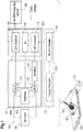
- Fig.1 shows a hob 100 of a cooking appliance.
- a sensor system can be coupled to a control unit of the cooking appliance in order to be able to control a cooking process in a cookware 102 heated on the hob by means of the control unit as a function of process parameters (at least partially of the cookware 102).
- the sensor system has a mobile sensor unit 103, which can be coupled in particular via an integrated or connected radio transmission unit 105 to a radio transmission unit 101 of the cooking appliance.
- a mobile sensor unit 103 which can be coupled in particular via an integrated or connected radio transmission unit 105 to a radio transmission unit 101 of the cooking appliance.
- radio transmission unit 101 of the cooking appliance.
- Under a cookware here are e.g. Understood vessels that serve for the preparation of hot food, so in particular also cooking spoons, pans and frying pans.
- the sensor system thus consists in particular of the mobile sensor unit 103 with on the one hand at least one sensor 106 and the radio transmission unit 105 and on the other hand the radio transmission unit 101 on the hob 100 or on the cooking appliance.
- the radio transmission unit 105 of the sensor unit 103 is in particular a transmitting unit, but can also be designed as a transmitting / receiving unit or transceiver for possible bi-directional transmissions. In particular, it is a so-called low-power radio transceiver as the radio transmission unit 105.
- the radio transmission unit 101 is in particular a receiving unit on the cooking appliance, but can also be designed as a transmitting / receiving unit or transceiver for possible bidirectional transmissions.
- the receiving unit can be connected both internally and externally with a cable to the control unit of the cooking appliance.
- the mobile sensor unit 103 includes as functional units and electronic components 104 in addition to the sensor 106 and the radio transmission unit 105, a calibrated-free conditioning unit 107 coupled or connected therebetween.
- the calibration-free processing unit 107 comprises an analog signal conditioning unit 108 and a microcontroller 109 as a control unit.
- the analog signal conditioning unit 108 is coupled between the microcontroller 109 and the sensor 106.
- the radio transmission unit 105 is connected or coupled to the unit for calibration-free processing 107, in particular to its microcontroller 109.
- the microcontroller 109 has a digital-to-analog converter 110 whose output is applied to a multiplexer 111. Switchable further inputs or outputs of the multiplexer 111 are applied to the at least one sensor 106 and to a reference unit 112.
- the reference unit 112 In the case of a resistive sensor 106, the reference unit 112 is configured correspondingly resistive, and in the case of a capacitive sensor 106, the reference unit 112 is configured correspondingly capacitive.
- the senor 106 and the reference unit 112 are connected to inputs and outputs of another multiplexer 113.
- the other terminal of the further multiplexer 113 is applied to an input of an amplifier 114.
- the amplifier 114 is for signal or level matching.
- An output of the amplifier 114 is applied to an analog-to-digital converter 115.
- the analog / digital converter 115 is part of the microcontroller 109, for example.
- the microcontroller 109 also has an input / output interface 116.
- it is an interface for general purposes or for control or display purposes by further components, e.g. Switch or display elements.
- the input / output interface 116 applies signals or values to the two multiplexers 111, 113.
- the sensor part with the at least one sensor 106 may, for example, in addition to several temperature sensors, which can simultaneously detect the level of a pot, pressure, moisture, PH, conductivity and viscosity sensors included.
- a heat capacity can be calculated, for example, via the decay curves in the clocked heating mode.
- the analog signal processing includes in particular the Provision of required measuring voltages and currents, a multiplexer circuit with the multiplexers 111, 113 for addressing also a plurality of sensors 106, the reference unit 112, with which a calibration of the sensors 106 can be omitted, as well as in the amplifier 114, a range adaptation of the output voltages of the sensors 106 to the Input range of the analog-to-digital converter 115 of the microcontroller 109th
- the microcontroller 109 which, inter alia, assumes the energy management of the sensor-side sensor system, detects sensor signals and carries out a first signal evaluation. Subsequently, the digital sensor values are transmitted by means of the radio transmission unit 105, in particular of a low-power radio transceiver, to the receiving station or the radio transmission unit 101 of the cooking appliance. In this case, only or partial changes in the data (differential transmission) can be transmitted to reduce the transfer volume. After a certain period of time, a complete data frame (keyframe) can be transmitted, which is used to match the values in the hob.
- the radio transmission unit 105 in particular of a low-power radio transceiver
- the sensor system For supplying energy, in particular for applying a voltage or a current, the sensor system has an energy or power supply unit 117.
- the energy or power supply unit 117 comprises a so-called energy harvester 118.
- Energy harvester 118 in general terms, is a device that receives and releases energy that is freely available in the environment as voltage to other units.
- energy harvester 118 has a photocell which converts light into voltage. But also for the use of other forms of energy such. From heat or by conversion of chemical substances energy harvester 118 can be designed to generate electricity.
- Energy taken up by the energy harvester 118 is applied in the form of a voltage to a DC-to-DC converter 119.
- the energy or voltage supply unit 117 applies the corresponding energy or voltage to the unit for calibration-free preparation 107.
- the calibration-free processing unit 107 applies the applied energy to its individual components, in particular to its microcontroller 109 and to the analog signal conditioning unit 108.
- both data to be transmitted and energy are applied to the radio transmission unit 105.
- a preferred unit for calibration-free preparation or calibration-free control is in EP 2 199 766 A2 described.
- a multiplexer is typically located at the input of the measuring branch, via which two internal calibration resistors and a plurality of external resistance temperature sensors to be measured are connected as such sensors 106 one after the other to the measuring branch.
- the two known calibration resistances are conventionally first measured as reference variables of the reference 112 and thereafter the resistance temperature sensor to be determined or, in succession, the resistance temperature sensors to be determined.
- the ohmic resistance of the resistors is measured in each case, or in each case a variable is measured which is proportional to the ohmic resistance.
- a measuring current is impressed and measured the voltage drop across the connected resistor.
- the two calibration resistors are usually chosen such that one calibration resistor is close to the minimum value of the measurement range and the other calibration resistor is close to the maximum value of the measurement range.
- the two predefined calibration resistance values and the associated real measured values define a straight line along which interpolation and / or extrapolation can take place. By means of a linear interpolation or extrapolation on this straight line, the measured value of the resistance temperature sensor is used to calculate its ohmic resistance and thus the sensed temperature.
- the width of the maximum measuring range can be selected by setting the evaluation electronics.
- the structural design of the sensor system as a mobile unit or as part of the mobile unit, for example in the form of a cookware, z. As a spoon, or in the form of a sensor with flexible sensors.
- the electronics are preferably outside the pot, while the actual sensor value measurements take place in the pot. This also allows undisturbed radio transmission, since the radio signals do not have to penetrate a pot wall.
Landscapes
- Physics & Mathematics (AREA)
- General Physics & Mathematics (AREA)
- Arrangements For Transmission Of Measured Signals (AREA)
- Electric Stoves And Ranges (AREA)
- Cookers (AREA)
Priority Applications (1)
| Application Number | Priority Date | Filing Date | Title |
|---|---|---|---|
| PL12813846T PL2802844T3 (pl) | 2012-01-11 | 2012-12-20 | Układ czujników do urządzenia do gotowania |
Applications Claiming Priority (2)
| Application Number | Priority Date | Filing Date | Title |
|---|---|---|---|
| DE102012200295A DE102012200295A1 (de) | 2012-01-11 | 2012-01-11 | Sensorsystem für ein Gargerät |
| PCT/EP2012/076414 WO2013104510A1 (de) | 2012-01-11 | 2012-12-20 | Sensorsystem für ein gargerät |
Publications (2)
| Publication Number | Publication Date |
|---|---|
| EP2802844A1 EP2802844A1 (de) | 2014-11-19 |
| EP2802844B1 true EP2802844B1 (de) | 2019-03-20 |
Family
ID=47557089
Family Applications (1)
| Application Number | Title | Priority Date | Filing Date |
|---|---|---|---|
| EP12813846.8A Active EP2802844B1 (de) | 2012-01-11 | 2012-12-20 | Sensorsystem für ein gargerät |
Country Status (5)
| Country | Link |
|---|---|
| EP (1) | EP2802844B1 (pl) |
| DE (1) | DE102012200295A1 (pl) |
| PL (1) | PL2802844T3 (pl) |
| TR (1) | TR201904723T4 (pl) |
| WO (1) | WO2013104510A1 (pl) |
Families Citing this family (6)
| Publication number | Priority date | Publication date | Assignee | Title |
|---|---|---|---|---|
| DE102014114901A1 (de) * | 2014-10-14 | 2016-04-14 | Frima International Ag | Gargerät sowie Verfahren zur Erfassung eines Prozessparameters eines Garprozesses |
| DE102015101707B4 (de) * | 2015-02-06 | 2016-09-29 | Miele & Cie. Kg | Kochsystem und Verfahren zum Betreiben eines Kochsystems |
| AT517723B1 (de) * | 2015-09-15 | 2017-06-15 | Fluxron Solutions Ag | Kochhilfsvorrichtung |
| AT517611B1 (de) * | 2015-09-15 | 2017-03-15 | Fluxron Solutions Ag | Kochhilfsvorrichtung |
| DE102015117310A1 (de) * | 2015-10-12 | 2017-04-13 | Rational Aktiengesellschaft | Verfahren zur Ansteuerung einer Innenbeleuchtung eines Gargeräts sowie Gargerät |
| DE102018100669A1 (de) * | 2018-01-12 | 2019-07-18 | Rational International Ag | Verfahren zur Bestimmung der Temperaturempfindlichkeit eines Gargutes sowie Gargerät |
Citations (1)
| Publication number | Priority date | Publication date | Assignee | Title |
|---|---|---|---|---|
| DE102007017632A1 (de) * | 2007-04-13 | 2008-10-16 | Sentec Elektronik Gmbh | Sensoranordnung |
Family Cites Families (13)
| Publication number | Priority date | Publication date | Assignee | Title |
|---|---|---|---|---|
| CA1200583A (en) * | 1982-03-03 | 1986-02-11 | Shunichi Taguchi | High-frequency heating apparatus with wireless temperature probe |
| DE3225486A1 (de) * | 1982-07-08 | 1984-01-12 | Bbc Brown Boveri & Cie | Verfahren und vorrichtung zur speisung von messstationen eines fernmesssystems |
| EP1037508A1 (de) * | 1999-03-10 | 2000-09-20 | Inducs A.G. | Induktiver Kochherd mit Temperaturregelung |
| ITVA20010005U1 (it) * | 2001-03-09 | 2002-09-09 | Whirlpool Co | Dispositivo di controllo automatico di un processo di cottura e/o riscaldamento di vivande |
| ITMO20040193A1 (it) * | 2004-07-23 | 2004-10-23 | Angelo Grandi Cucine Spa | Sistema e sonda per la rivealzione di un parametro |
| DE102005023468B4 (de) | 2005-05-20 | 2009-08-20 | Electrolux Home Products Corporation N.V. | Gargerät |
| DE102005043771A1 (de) * | 2005-09-13 | 2007-03-15 | Endress + Hauser Flowtec Ag | Verfahren zur Energieversorgung eines Feldgerätes der Automatisierungstechnik |
| DE102007018245A1 (de) * | 2007-03-30 | 2008-10-02 | E.G.O. Elektro-Gerätebau GmbH | Temperatursonde für einen Ofen, Ofen und Verfahren zum Betrieb eines Ofens |
| US20090188396A1 (en) * | 2007-08-06 | 2009-07-30 | Hofmann Matthias C | Oven with wireless temperature sensor for use in monitoring food temperature |
| US8508193B2 (en) * | 2008-10-08 | 2013-08-13 | Infinite Power Solutions, Inc. | Environmentally-powered wireless sensor module |
| DE102008054902B4 (de) | 2008-12-18 | 2011-11-10 | BSH Bosch und Siemens Hausgeräte GmbH | Kochgeschirr mit Temperaturmessschaltung |
| MY149369A (en) * | 2009-02-11 | 2013-08-30 | Mimos Bhd | Wireless sensor network with ambient energy harvesting |
| DE102009003105B4 (de) * | 2009-05-14 | 2019-06-06 | BSH Hausgeräte GmbH | Transponder für ein Gargeschirr, Gargeschirr mit einem Transponder und Verfahren zum Ausrüsten eines Gargeschirrs mit einem Transponder |
-
2012
- 2012-01-11 DE DE102012200295A patent/DE102012200295A1/de not_active Withdrawn
- 2012-12-20 WO PCT/EP2012/076414 patent/WO2013104510A1/de not_active Ceased
- 2012-12-20 PL PL12813846T patent/PL2802844T3/pl unknown
- 2012-12-20 TR TR2019/04723T patent/TR201904723T4/tr unknown
- 2012-12-20 EP EP12813846.8A patent/EP2802844B1/de active Active
Patent Citations (1)
| Publication number | Priority date | Publication date | Assignee | Title |
|---|---|---|---|---|
| DE102007017632A1 (de) * | 2007-04-13 | 2008-10-16 | Sentec Elektronik Gmbh | Sensoranordnung |
Also Published As
| Publication number | Publication date |
|---|---|
| TR201904723T4 (tr) | 2019-05-21 |
| DE102012200295A1 (de) | 2013-07-11 |
| EP2802844A1 (de) | 2014-11-19 |
| WO2013104510A1 (de) | 2013-07-18 |
| PL2802844T3 (pl) | 2019-09-30 |
Similar Documents
| Publication | Publication Date | Title |
|---|---|---|
| EP2802844B1 (de) | Sensorsystem für ein gargerät | |
| EP1664760B1 (de) | Steckmodul für einen flüssigkeits- oder gassensor mit galvanisch entkoppelter übertragungsstrecke | |
| DE102013111714A1 (de) | Verfahren zur Funktionseinstellung einer Messstelle und Messstelle | |
| DE102013103454A1 (de) | Messumformerspeisegerät, System zum Einsatz in der Automatisierungstechnik, sowie Verfahren zum Bedienen eines solchen Systems | |
| EP3566032A1 (de) | Temperatur-grenzwertgeber | |
| DE102008043336B4 (de) | Modulares Messgerät mit verteilten Daten und Algorithmen | |
| EP1926987A1 (de) | Steckmodul für einen flüssigkeits- oder gassensor | |
| DE102013109809A1 (de) | Verfahren zur Bestimmung der Vergleichsstellentemperatur eines Thermoelements | |
| DE102010062657B4 (de) | Bereitstellung von Kalibrierungsdaten zu Messeinrichtungen | |
| WO2018095648A1 (de) | Kommunikations-adapter für einen transmitter eines feldgeräts | |
| DE102009006662A1 (de) | Parametriereinrichtung und Verfahren zu ihrem Betrieb | |
| DE10130215B4 (de) | Meßgrößenaufnehmer mit angeschlossenem Datenspeicher | |
| DE102015101707A1 (de) | Kochsystem und Verfahren zum Betreiben eines Kochsystems | |
| EP3513698A1 (de) | Verfahren zum betreiben eines heizelements | |
| DE102018106940B4 (de) | Messsystem und Verfahren zur verteilten Energiemessung | |
| DE102020100397A1 (de) | Sensor, Sensoranordnung, Sensorsystem und Verfahren zum Betreiben eines Sensorsystems | |
| DE102016124796A1 (de) | Sensorkopfmodul zur kontinuierlichen automatisierten Datenerfassung | |
| DE102014112019B4 (de) | Sensoreinheit zur Temperaturüberwachung sowie zur Temperaturkompensation eines Ultraschallsensors sowie eine Anordnung enthaltend eine Sensoreinheit und einen Ultraschallsensor | |
| DE19543151A1 (de) | Anordnung zur Fahrzeugerfassung und Verfahren zu deren Betrieb | |
| DE102007022188A1 (de) | Sensorvorrichtung, elektrisches Modul, Steuergerät sowie Gesamtsystem | |
| WO2007054045A1 (de) | Lötvorrichtung mit rechnerbasiertem sensorsystem | |
| DE102014111805B4 (de) | Vorrichtung zur Ermittlung einer Messgröße | |
| DE102014215666A1 (de) | Steuerungsvorrichtung sowie elektrischer Verbraucher für ein Kraftfahrzeug | |
| WO2016078916A1 (de) | MESSVORRICHTUNG ZUR MESSUNG EINER ELEKTRISCHEN GRÖßE | |
| DE102014009711B4 (de) | Verfahren zur Kalibrierung eines Messsystems |
Legal Events
| Date | Code | Title | Description |
|---|---|---|---|
| PUAI | Public reference made under article 153(3) epc to a published international application that has entered the european phase |
Free format text: ORIGINAL CODE: 0009012 |
|
| 17P | Request for examination filed |
Effective date: 20140811 |
|
| AK | Designated contracting states |
Kind code of ref document: A1 Designated state(s): AL AT BE BG CH CY CZ DE DK EE ES FI FR GB GR HR HU IE IS IT LI LT LU LV MC MK MT NL NO PL PT RO RS SE SI SK SM TR |
|
| RAP1 | Party data changed (applicant data changed or rights of an application transferred) |
Owner name: BSH HAUSGERAETE GMBH |
|
| DAX | Request for extension of the european patent (deleted) | ||
| STAA | Information on the status of an ep patent application or granted ep patent |
Free format text: STATUS: EXAMINATION IS IN PROGRESS |
|
| 17Q | First examination report despatched |
Effective date: 20180123 |
|
| GRAP | Despatch of communication of intention to grant a patent |
Free format text: ORIGINAL CODE: EPIDOSNIGR1 |
|
| STAA | Information on the status of an ep patent application or granted ep patent |
Free format text: STATUS: GRANT OF PATENT IS INTENDED |
|
| INTG | Intention to grant announced |
Effective date: 20181024 |
|
| GRAS | Grant fee paid |
Free format text: ORIGINAL CODE: EPIDOSNIGR3 |
|
| GRAA | (expected) grant |
Free format text: ORIGINAL CODE: 0009210 |
|
| STAA | Information on the status of an ep patent application or granted ep patent |
Free format text: STATUS: THE PATENT HAS BEEN GRANTED |
|
| AK | Designated contracting states |
Kind code of ref document: B1 Designated state(s): AL AT BE BG CH CY CZ DE DK EE ES FI FR GB GR HR HU IE IS IT LI LT LU LV MC MK MT NL NO PL PT RO RS SE SI SK SM TR |
|
| REG | Reference to a national code |
Ref country code: GB Ref legal event code: FG4D Free format text: NOT ENGLISH |
|
| REG | Reference to a national code |
Ref country code: CH Ref legal event code: EP |
|
| REG | Reference to a national code |
Ref country code: DE Ref legal event code: R096 Ref document number: 502012014484 Country of ref document: DE |
|
| REG | Reference to a national code |
Ref country code: AT Ref legal event code: REF Ref document number: 1111019 Country of ref document: AT Kind code of ref document: T Effective date: 20190415 |
|
| REG | Reference to a national code |
Ref country code: IE Ref legal event code: FG4D Free format text: LANGUAGE OF EP DOCUMENT: GERMAN |
|
| REG | Reference to a national code |
Ref country code: NL Ref legal event code: MP Effective date: 20190320 |
|
| PG25 | Lapsed in a contracting state [announced via postgrant information from national office to epo] |
Ref country code: NO Free format text: LAPSE BECAUSE OF FAILURE TO SUBMIT A TRANSLATION OF THE DESCRIPTION OR TO PAY THE FEE WITHIN THE PRESCRIBED TIME-LIMIT Effective date: 20190620 Ref country code: SE Free format text: LAPSE BECAUSE OF FAILURE TO SUBMIT A TRANSLATION OF THE DESCRIPTION OR TO PAY THE FEE WITHIN THE PRESCRIBED TIME-LIMIT Effective date: 20190320 Ref country code: FI Free format text: LAPSE BECAUSE OF FAILURE TO SUBMIT A TRANSLATION OF THE DESCRIPTION OR TO PAY THE FEE WITHIN THE PRESCRIBED TIME-LIMIT Effective date: 20190320 Ref country code: LT Free format text: LAPSE BECAUSE OF FAILURE TO SUBMIT A TRANSLATION OF THE DESCRIPTION OR TO PAY THE FEE WITHIN THE PRESCRIBED TIME-LIMIT Effective date: 20190320 |
|
| REG | Reference to a national code |
Ref country code: LT Ref legal event code: MG4D |
|
| PG25 | Lapsed in a contracting state [announced via postgrant information from national office to epo] |
Ref country code: BG Free format text: LAPSE BECAUSE OF FAILURE TO SUBMIT A TRANSLATION OF THE DESCRIPTION OR TO PAY THE FEE WITHIN THE PRESCRIBED TIME-LIMIT Effective date: 20190620 Ref country code: GR Free format text: LAPSE BECAUSE OF FAILURE TO SUBMIT A TRANSLATION OF THE DESCRIPTION OR TO PAY THE FEE WITHIN THE PRESCRIBED TIME-LIMIT Effective date: 20190621 Ref country code: NL Free format text: LAPSE BECAUSE OF FAILURE TO SUBMIT A TRANSLATION OF THE DESCRIPTION OR TO PAY THE FEE WITHIN THE PRESCRIBED TIME-LIMIT Effective date: 20190320 Ref country code: RS Free format text: LAPSE BECAUSE OF FAILURE TO SUBMIT A TRANSLATION OF THE DESCRIPTION OR TO PAY THE FEE WITHIN THE PRESCRIBED TIME-LIMIT Effective date: 20190320 Ref country code: HR Free format text: LAPSE BECAUSE OF FAILURE TO SUBMIT A TRANSLATION OF THE DESCRIPTION OR TO PAY THE FEE WITHIN THE PRESCRIBED TIME-LIMIT Effective date: 20190320 Ref country code: LV Free format text: LAPSE BECAUSE OF FAILURE TO SUBMIT A TRANSLATION OF THE DESCRIPTION OR TO PAY THE FEE WITHIN THE PRESCRIBED TIME-LIMIT Effective date: 20190320 |
|
| PG25 | Lapsed in a contracting state [announced via postgrant information from national office to epo] |
Ref country code: RO Free format text: LAPSE BECAUSE OF FAILURE TO SUBMIT A TRANSLATION OF THE DESCRIPTION OR TO PAY THE FEE WITHIN THE PRESCRIBED TIME-LIMIT Effective date: 20190320 Ref country code: IT Free format text: LAPSE BECAUSE OF FAILURE TO SUBMIT A TRANSLATION OF THE DESCRIPTION OR TO PAY THE FEE WITHIN THE PRESCRIBED TIME-LIMIT Effective date: 20190320 Ref country code: CZ Free format text: LAPSE BECAUSE OF FAILURE TO SUBMIT A TRANSLATION OF THE DESCRIPTION OR TO PAY THE FEE WITHIN THE PRESCRIBED TIME-LIMIT Effective date: 20190320 Ref country code: SK Free format text: LAPSE BECAUSE OF FAILURE TO SUBMIT A TRANSLATION OF THE DESCRIPTION OR TO PAY THE FEE WITHIN THE PRESCRIBED TIME-LIMIT Effective date: 20190320 Ref country code: EE Free format text: LAPSE BECAUSE OF FAILURE TO SUBMIT A TRANSLATION OF THE DESCRIPTION OR TO PAY THE FEE WITHIN THE PRESCRIBED TIME-LIMIT Effective date: 20190320 Ref country code: AL Free format text: LAPSE BECAUSE OF FAILURE TO SUBMIT A TRANSLATION OF THE DESCRIPTION OR TO PAY THE FEE WITHIN THE PRESCRIBED TIME-LIMIT Effective date: 20190320 Ref country code: PT Free format text: LAPSE BECAUSE OF FAILURE TO SUBMIT A TRANSLATION OF THE DESCRIPTION OR TO PAY THE FEE WITHIN THE PRESCRIBED TIME-LIMIT Effective date: 20190720 Ref country code: ES Free format text: LAPSE BECAUSE OF FAILURE TO SUBMIT A TRANSLATION OF THE DESCRIPTION OR TO PAY THE FEE WITHIN THE PRESCRIBED TIME-LIMIT Effective date: 20190320 |
|
| PG25 | Lapsed in a contracting state [announced via postgrant information from national office to epo] |
Ref country code: SM Free format text: LAPSE BECAUSE OF FAILURE TO SUBMIT A TRANSLATION OF THE DESCRIPTION OR TO PAY THE FEE WITHIN THE PRESCRIBED TIME-LIMIT Effective date: 20190320 |
|
| PG25 | Lapsed in a contracting state [announced via postgrant information from national office to epo] |
Ref country code: IS Free format text: LAPSE BECAUSE OF FAILURE TO SUBMIT A TRANSLATION OF THE DESCRIPTION OR TO PAY THE FEE WITHIN THE PRESCRIBED TIME-LIMIT Effective date: 20190720 |
|
| REG | Reference to a national code |
Ref country code: DE Ref legal event code: R097 Ref document number: 502012014484 Country of ref document: DE |
|
| PLBE | No opposition filed within time limit |
Free format text: ORIGINAL CODE: 0009261 |
|
| STAA | Information on the status of an ep patent application or granted ep patent |
Free format text: STATUS: NO OPPOSITION FILED WITHIN TIME LIMIT |
|
| PG25 | Lapsed in a contracting state [announced via postgrant information from national office to epo] |
Ref country code: DK Free format text: LAPSE BECAUSE OF FAILURE TO SUBMIT A TRANSLATION OF THE DESCRIPTION OR TO PAY THE FEE WITHIN THE PRESCRIBED TIME-LIMIT Effective date: 20190320 |
|
| 26N | No opposition filed |
Effective date: 20200102 |
|
| PG25 | Lapsed in a contracting state [announced via postgrant information from national office to epo] |
Ref country code: SI Free format text: LAPSE BECAUSE OF FAILURE TO SUBMIT A TRANSLATION OF THE DESCRIPTION OR TO PAY THE FEE WITHIN THE PRESCRIBED TIME-LIMIT Effective date: 20190320 |
|
| REG | Reference to a national code |
Ref country code: CH Ref legal event code: PL |
|
| REG | Reference to a national code |
Ref country code: BE Ref legal event code: MM Effective date: 20191231 |
|
| PG25 | Lapsed in a contracting state [announced via postgrant information from national office to epo] |
Ref country code: MC Free format text: LAPSE BECAUSE OF FAILURE TO SUBMIT A TRANSLATION OF THE DESCRIPTION OR TO PAY THE FEE WITHIN THE PRESCRIBED TIME-LIMIT Effective date: 20190320 |
|
| GBPC | Gb: european patent ceased through non-payment of renewal fee |
Effective date: 20191220 |
|
| PG25 | Lapsed in a contracting state [announced via postgrant information from national office to epo] |
Ref country code: IE Free format text: LAPSE BECAUSE OF NON-PAYMENT OF DUE FEES Effective date: 20191220 Ref country code: GB Free format text: LAPSE BECAUSE OF NON-PAYMENT OF DUE FEES Effective date: 20191220 Ref country code: FR Free format text: LAPSE BECAUSE OF NON-PAYMENT OF DUE FEES Effective date: 20191231 Ref country code: LU Free format text: LAPSE BECAUSE OF NON-PAYMENT OF DUE FEES Effective date: 20191220 |
|
| PG25 | Lapsed in a contracting state [announced via postgrant information from national office to epo] |
Ref country code: LI Free format text: LAPSE BECAUSE OF NON-PAYMENT OF DUE FEES Effective date: 20191231 Ref country code: CH Free format text: LAPSE BECAUSE OF NON-PAYMENT OF DUE FEES Effective date: 20191231 Ref country code: BE Free format text: LAPSE BECAUSE OF NON-PAYMENT OF DUE FEES Effective date: 20191231 |
|
| REG | Reference to a national code |
Ref country code: AT Ref legal event code: MM01 Ref document number: 1111019 Country of ref document: AT Kind code of ref document: T Effective date: 20191220 |
|
| PG25 | Lapsed in a contracting state [announced via postgrant information from national office to epo] |
Ref country code: CY Free format text: LAPSE BECAUSE OF FAILURE TO SUBMIT A TRANSLATION OF THE DESCRIPTION OR TO PAY THE FEE WITHIN THE PRESCRIBED TIME-LIMIT Effective date: 20190320 Ref country code: AT Free format text: LAPSE BECAUSE OF NON-PAYMENT OF DUE FEES Effective date: 20191220 |
|
| PG25 | Lapsed in a contracting state [announced via postgrant information from national office to epo] |
Ref country code: MT Free format text: LAPSE BECAUSE OF FAILURE TO SUBMIT A TRANSLATION OF THE DESCRIPTION OR TO PAY THE FEE WITHIN THE PRESCRIBED TIME-LIMIT Effective date: 20190320 Ref country code: HU Free format text: LAPSE BECAUSE OF FAILURE TO SUBMIT A TRANSLATION OF THE DESCRIPTION OR TO PAY THE FEE WITHIN THE PRESCRIBED TIME-LIMIT; INVALID AB INITIO Effective date: 20121220 |
|
| PGFP | Annual fee paid to national office [announced via postgrant information from national office to epo] |
Ref country code: DE Payment date: 20211231 Year of fee payment: 10 |
|
| PGFP | Annual fee paid to national office [announced via postgrant information from national office to epo] |
Ref country code: PL Payment date: 20211209 Year of fee payment: 10 |
|
| PGFP | Annual fee paid to national office [announced via postgrant information from national office to epo] |
Ref country code: TR Payment date: 20211215 Year of fee payment: 10 |
|
| PG25 | Lapsed in a contracting state [announced via postgrant information from national office to epo] |
Ref country code: MK Free format text: LAPSE BECAUSE OF FAILURE TO SUBMIT A TRANSLATION OF THE DESCRIPTION OR TO PAY THE FEE WITHIN THE PRESCRIBED TIME-LIMIT Effective date: 20190320 |
|
| REG | Reference to a national code |
Ref country code: DE Ref legal event code: R119 Ref document number: 502012014484 Country of ref document: DE |
|
| PG25 | Lapsed in a contracting state [announced via postgrant information from national office to epo] |
Ref country code: DE Free format text: LAPSE BECAUSE OF NON-PAYMENT OF DUE FEES Effective date: 20230701 |
|
| PG25 | Lapsed in a contracting state [announced via postgrant information from national office to epo] |
Ref country code: PL Free format text: LAPSE BECAUSE OF NON-PAYMENT OF DUE FEES Effective date: 20221220 |