EP2802802B1 - Pipe repair means - Google Patents
Pipe repair means Download PDFInfo
- Publication number
- EP2802802B1 EP2802802B1 EP13704624.9A EP13704624A EP2802802B1 EP 2802802 B1 EP2802802 B1 EP 2802802B1 EP 13704624 A EP13704624 A EP 13704624A EP 2802802 B1 EP2802802 B1 EP 2802802B1
- Authority
- EP
- European Patent Office
- Prior art keywords
- pipe
- sheet
- solder
- damaged
- recess
- Prior art date
- Legal status (The legal status is an assumption and is not a legal conclusion. Google has not performed a legal analysis and makes no representation as to the accuracy of the status listed.)
- Not-in-force
Links
Images

Classifications
-
- F—MECHANICAL ENGINEERING; LIGHTING; HEATING; WEAPONS; BLASTING
- F16—ENGINEERING ELEMENTS AND UNITS; GENERAL MEASURES FOR PRODUCING AND MAINTAINING EFFECTIVE FUNCTIONING OF MACHINES OR INSTALLATIONS; THERMAL INSULATION IN GENERAL
- F16L—PIPES; JOINTS OR FITTINGS FOR PIPES; SUPPORTS FOR PIPES, CABLES OR PROTECTIVE TUBING; MEANS FOR THERMAL INSULATION IN GENERAL
- F16L55/00—Devices or appurtenances for use in, or in connection with, pipes or pipe systems
- F16L55/16—Devices for covering leaks in pipes or hoses, e.g. hose-menders
- F16L55/168—Devices for covering leaks in pipes or hoses, e.g. hose-menders from outside the pipe
- F16L55/1683—Devices for covering leaks in pipes or hoses, e.g. hose-menders from outside the pipe by means of a patch which is fixed on the wall of the pipe by means of an adhesive, a weld or the like
Definitions
- the present invention relates to device for repairing pipes and in particular a device securable over a breach in a pipe to patch a leak therein.
- US Patent 4890373 One example of a more localised approach to repairing a leak in a pipe without replacing the damaged area of pipe work is described in US Patent 4890373 .
- the localised approach makes use of a patch or clip that is fixed, usually by a bonding agent or adhesive, over the damaged area of pipe.
- the present application seeks to provide an improved pipe repairing means for use in the localised repair of damaged pipe work using solder rather than a bonding agent to secure the repair in place.
- the present invention provides a method of manufacturing a pipe repair device comprising: a) providing a sheet of malleable metal; b) forming a continuous recess or channel in one side of the sheet so as to define a distinct inner central region and outer perimeter region on the sheet; c) providing a solder material in the recess; and d) forming the sheet into an incomplete cylinder shape.
- incomplete cylinder shape refers to a cylinder with a gap running along it length.
- the sheet material used to manufacture the repair device of the present invention must be malleable so that the recessed portion can easily be formed therein and also so that sheet can be formed into the required shape.
- the material used is copper as this is the most common material used in the repair of pipes.
- the sheet is rectangular in shape.
- the solder may be heated, so that it flows in to the recess, and then allowed to cool so that it solidifies in the recess.
- the sheet may be formed into the incomplete cylinder shape before the solder is provided.
- the sheet may be formed into the incomplete cylinder shape after the solder is provided.
- the sheet may be formed in to an incomplete cylinder shape having a gap between the two edges of the sheet that is between 25 to 40%, and further preferably 30% of the entire circumference of the notional complete cylinder. This ensures that the device can be clipped onto the pipe that is being repaired.
- the present invention also provides a pipe repair device for repairing damaged sections of piping, said device being shaped so as to snugly clip around a major part of the circumference of a damaged pipe so as to cover the damaged area of the pipe, and wherein the device is characterised in that an inner surface on the device has a recessed portion within which a reservoir of solder is retained.
- the recessed portion may be located in from the sides of the device. In this way the outer region of the inner surface can be bonded to the pipe by the solder. It is noted that as soon as the solder begins to seep out from behind the device the plumber can stop heating the device.
- the recessed portion may comprise a continuous channel that provides a perimeter around a central region of the inner surface of device. In this way the damaged region of the pipe can be completely surrounded by solder when it is aligned with the central region.
- the recessed portion may also protrude from an outer surface of the device located on the reverse of the inner surface.
- the protruding portion can be used to guide the plumber when locating the device over the damaged region of the pipe.
- the present invention also provides a method of repairing a damaged pipe comprising the steps of: a) locating the device of the present invention over the damaged section of pipe; and b) heating the outer surface of the device on the opposite side of the device to the solder containing recess.
- the method may further comprise the step of aligning the damaged section of pipe with the central region of the inner surface of the device.
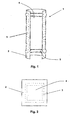
- the pipe repair device of the present invention will be appreciated from consideration of the figures, in which in can be seen that the device 1 takes the form of a patch or clip which has an incomplete cylinder shaped formed from a suitable material such as copper.
- the device must be shaped so as to ensure it can be 'clipped' around the pipe that is to be repaired.
- gap between the two edges of the incomplete cylinder shaped body 2 of the device 1 must extend around less that half of the circumference. It is envisaged that the gap would extend around 25-40% of the cylinder's circumference and more preferably about 30%.
- the gap between the two edges of the incomplete cylinder shaped body 2 of the device 1 must not be too small to enable the device to be forced on to a section of pipe without causing damage.
- a recessed region or recess 3 On the inner surface of the body 2 is provided a recessed region or recess 3.
- a reservoir of solder material 5 Within the recess.3 is a reservoir of solder material 5.
- the recess 3 is located in from the edges of the device 1 so as to provide a surface which the solder can seal to the surface of the pipe being repaired.
- the process starts by selecting a rectangular sheet of suitable material, such as copper, having suitable dimensions to form an incomplete cylinder body 2 in accordance with the physical characteristics described above.
- solder 5 can be introduced into the recess 3. This can be done by heating the solder until it is fluid enough to flow into the recess.
- the sheet can be allowed to cool, thus allowing the solder to solidify in the recess. Any excess solder can be removed at this time
- the sheet can be bent into the required incomplete cylinder shape, possibly using a standard length of pipe (or a mould with identical dimensions). Once formed the device 1 can be slid off the end of the pipe/mould to ensure the device retains its shape.
- the device 1 of the present invention enables a much quicker and easier repair to be carried out by the plumber.
- a plumber To repair the damaged pipe 6 a plumber first selects the appropriate size of repair device 1 and then clips it on to the damaged pipe 6.
- the device In order for the device to effectively seal the leak the device must be positioned so that the recess 3 completely surrounds the hole in the pipe. This alignment process is assisted by opposing side of the recess which extend from the outer surface of the device 1.
- the plumber can apply heat to the outer surface of the device around the area of the recess. In this way the solder 5 is caused to melt and form a bond between the pipe and the device, thereby affecting a repair of the pipe once the solder cools again.
- the device of the present invention is considered particularly useful when repairing hard to reach pipe work or damaged areas of pipes that face towards walls for example.
Description
- The present invention relates to device for repairing pipes and in particular a device securable over a breach in a pipe to patch a leak therein.
- Systems of pipe work are used to facilitate the transport of fluids of various types around domestic and commercial properties. The most common forms of fluid transported by piping are water and gas.
- Over time, or as a result of mechanical stresses, pipe work can become damaged leading to the formation of leaks. Various approaches to repairing such leaks are known, with the approach used being determined by factors such as the size of the hole and its location.
- In situations where the damaged pipe work can be accessed without causing too much disruption a plumber can simply replace all or a large portion of the damaged pipe. Depending on the nature of the repair this may or may not require soldering to seal the joint between the replacement pipe and the rest of the system.
- However in circumstances where the damaged pipe work cannot easily be accessed, or to do so would cause a large amount of disruption which would require subsequent repairs to make the area good again (e.g. plastering, decorating, etc..), there is a need for a more localised repair of the leak.
- One example of a more localised approach to repairing a leak in a pipe without replacing the damaged area of pipe work is described in
US Patent 4890373 . The localised approach makes use of a patch or clip that is fixed, usually by a bonding agent or adhesive, over the damaged area of pipe. - The use of solder to seal the patch over the damaged area is also described in the US patent.
- The present application seeks to provide an improved pipe repairing means for use in the localised repair of damaged pipe work using solder rather than a bonding agent to secure the repair in place.
- The present invention provides a method of manufacturing a pipe repair device comprising: a) providing a sheet of malleable metal; b) forming a continuous recess or channel in one side of the sheet so as to define a distinct inner central region and outer perimeter region on the sheet; c) providing a solder material in the recess; and d) forming the sheet into an incomplete cylinder shape.
- It will be appreciated that the term incomplete cylinder shape refers to a cylinder with a gap running along it length.
- The sheet material used to manufacture the repair device of the present invention must be malleable so that the recessed portion can easily be formed therein and also so that sheet can be formed into the required shape. Preferably the material used is copper as this is the most common material used in the repair of pipes. Preferably the sheet is rectangular in shape.
- In order to get the solder into the recess preferably the solder may be heated, so that it flows in to the recess, and then allowed to cool so that it solidifies in the recess.
- Preferably the sheet may be formed into the incomplete cylinder shape before the solder is provided. Alternatively the sheet may be formed into the incomplete cylinder shape after the solder is provided.
- Preferably the sheet may be formed in to an incomplete cylinder shape having a gap between the two edges of the sheet that is between 25 to 40%, and further preferably 30% of the entire circumference of the notional complete cylinder. This ensures that the device can be clipped onto the pipe that is being repaired.
- It is appreciated that alternative means of enabling the device to be clipped onto the pipe could be employed without departing from the general concept of the present invention.
- The present invention also provides a pipe repair device for repairing damaged sections of piping, said device being shaped so as to snugly clip around a major part of the circumference of a damaged pipe so as to cover the damaged area of the pipe, and wherein the device is characterised in that an inner surface on the device has a recessed portion within which a reservoir of solder is retained.
- Preferably the recessed portion may be located in from the sides of the device. In this way the outer region of the inner surface can be bonded to the pipe by the solder. It is noted that as soon as the solder begins to seep out from behind the device the plumber can stop heating the device.
- Preferably the recessed portion may comprise a continuous channel that provides a perimeter around a central region of the inner surface of device. In this way the damaged region of the pipe can be completely surrounded by solder when it is aligned with the central region.
- Preferably the recessed portion may also protrude from an outer surface of the device located on the reverse of the inner surface. In this way the protruding portion can be used to guide the plumber when locating the device over the damaged region of the pipe.
- The present invention also provides a method of repairing a damaged pipe comprising the steps of: a) locating the device of the present invention over the damaged section of pipe; and b) heating the outer surface of the device on the opposite side of the device to the solder containing recess.
- Preferably the method may further comprise the step of aligning the damaged section of pipe with the central region of the inner surface of the device.
- The present invention will now be described with reference to the preferred embodiment shown in the drawings, wherein:
-
Figure 1 shows a preferred embodiment of the pipe repair device of the present invention; -
Figure 2 shows the device offigure 1 in a flattened form; and -
Figure 3 shows a damaged pipe before and after a repair using the device offigure 1 . - The pipe repair device of the present invention will be appreciated from consideration of the figures, in which in can be seen that the
device 1 takes the form of a patch or clip which has an incomplete cylinder shaped formed from a suitable material such as copper. - It will be appreciated that pipes, such as gas and water pipes, come in a ranged of different standard sizes. In view of this fact it is envisaged that the actual dimensions (e.g. internal and external diameter) of the device of the present invention used to affect a repair will vary accordingly without departing from the scope of the present invention.
- However it is considered important that the device must be shaped so as to ensure it can be 'clipped' around the pipe that is to be repaired. In order to achieve this it is envisaged that gap between the two edges of the incomplete cylinder shaped
body 2 of thedevice 1 must extend around less that half of the circumference. It is envisaged that the gap would extend around 25-40% of the cylinder's circumference and more preferably about 30%. - Also, in order that the device might be 'clipped' on to the pipe, the gap between the two edges of the incomplete cylinder shaped
body 2 of thedevice 1 must not be too small to enable the device to be forced on to a section of pipe without causing damage. - On the inner surface of the
body 2 is provided a recessed region or recess 3. Therecess 3, which preferably projects outwards from the outer surface of thebody 2, defines a continuous perimeter around acentral region 4 of the inner surface. This can be better appreciated fromFigure 2 , which shows the device ofFigure 1 in its flattened form prior to being shaped into the above described incomplete cylinder shape. - Within the recess.3 is a reservoir of
solder material 5. Preferably therecess 3 is located in from the edges of thedevice 1 so as to provide a surface which the solder can seal to the surface of the pipe being repaired. - A method of manufacturing the device of the present invention will now be described. The process starts by selecting a rectangular sheet of suitable material, such as copper, having suitable dimensions to form an
incomplete cylinder body 2 in accordance with the physical characteristics described above. - The sheet is then pressed using a suitable machine to form the
recess 3 in a generally central location on the sheet. Once the recess is formedsolder 5 can be introduced into therecess 3. This can be done by heating the solder until it is fluid enough to flow into the recess. - Once the recess has been filed by the solder the sheet can be allowed to cool, thus allowing the solder to solidify in the recess. Any excess solder can be removed at this time
- Once the solder has cooled the sheet can be bent into the required incomplete cylinder shape, possibly using a standard length of pipe (or a mould with identical dimensions). Once formed the
device 1 can be slid off the end of the pipe/mould to ensure the device retains its shape. - Referring now to
Figure 3 the actual repair of a damaged pipe using the device of the present invention will now be described. Apipe 6 has been damaged and as a result is suffering from aleak 7. - The repair of this damaged pipe would normally be a time consuming job, which would typically require a plumber to cut out the damaged pipe and replace it with a new piece.
- The
device 1 of the present invention enables a much quicker and easier repair to be carried out by the plumber. To repair the damaged pipe 6 a plumber first selects the appropriate size ofrepair device 1 and then clips it on to the damagedpipe 6. - The plumber then slides or rotates the device until it is located over the leak. In order for the device to effectively seal the leak the device must be positioned so that the
recess 3 completely surrounds the hole in the pipe. This alignment process is assisted by opposing side of the recess which extend from the outer surface of thedevice 1. - Once the
device 1 is in position the plumber can apply heat to the outer surface of the device around the area of the recess. In this way thesolder 5 is caused to melt and form a bond between the pipe and the device, thereby affecting a repair of the pipe once the solder cools again. - The device of the present invention is considered particularly useful when repairing hard to reach pipe work or damaged areas of pipes that face towards walls for example.
Claims (14)
- A method of manufacturing a pipe repair (1) device comprising:a) providing a sheet of malleable metal;b) forming a continuous recess (3) or channel in one side of the sheet so as to define a distinct inner central region (4) and outer perimeter region on the sheet;c) providing a solder material (5) in the recess; andd) forming the sheet into an incomplete cylinder shape (2).
- The method of claim 1, wherein the sheet is made from copper.
- The method of claim 1 or 2, wherein the sheet is rectangular in shape.
- The method of claim 1, 2 or 3, wherein the solder (5) is heated, so that it flows in to the recess (3), and then allowed to cool, so that it solidifies in the recess (3).
- The method of any of claims 1 to 4, wherein the sheet is formed into the incomplete cylinder shape (2) before the solder (5) is provided.
- The method of any of claims 1 to 4, wherein the sheet is formed into the incomplete cylinder shape (2) after the solder (5) is provided.
- The method of any of claims 1 to 6, wherein the sheet is formed in to an incomplete cylinder shape (2) having a gap between the two edges of the sheet that is between 25 to 40% of the entire circumference of the cylinder.
- A pipe repair device (1) for repairing damaged sections of piping (6), said device being shaped so as to snugly clip around a major part of the circumference of a damaged pipe (6) so as to cover the damaged area of the pipe, and wherein the device is characterised in that an inner surface on the device has a recessed portion (3) within which a reservoir of solder (5) is retained.
- The device of claim 8, wherein the recessed portion (3) is located in from the sides of the device (1).
- The device (1) of claim 8 or 9, wherein the recessed portion (3) comprises a continuous channel that provides a perimeter around a central region (4) of the inner surface of device.
- The device (1) of claim 8, 9 or 10, wherein the recessed portion (3) also protrudes from an outer surface of the device located on the reverse of the inner surface.
- The device (1) of any of claims 8, 9, 10 or 11 as manufactured by the method according to any of claims 1 to 7.
- A method of repairing a damaged pipe (6) comprising the steps of:a) locating the device (1) of any of claims 8 to 12 over the damaged section of pipe (6); andb) heating the outer surface of the device (1) on the opposite side of the device (1) to the solder (5) containing recess (3).
- The method of claim 13 when using the device (1) of claim 10, further comprising the step of aligning the damaged section of pipe (6) with the central region (4) of the inner surface of the device.
Applications Claiming Priority (2)
| Application Number | Priority Date | Filing Date | Title |
|---|---|---|---|
| GB201200516A GB2498379B (en) | 2012-01-13 | 2012-01-13 | Pipe repair means |
| PCT/GB2013/050041 WO2013104908A2 (en) | 2012-01-13 | 2013-01-11 | Pipe repair means |
Publications (2)
| Publication Number | Publication Date |
|---|---|
| EP2802802A2 EP2802802A2 (en) | 2014-11-19 |
| EP2802802B1 true EP2802802B1 (en) | 2016-01-06 |
Family
ID=45813944
Family Applications (1)
| Application Number | Title | Priority Date | Filing Date |
|---|---|---|---|
| EP13704624.9A Not-in-force EP2802802B1 (en) | 2012-01-13 | 2013-01-11 | Pipe repair means |
Country Status (5)
| Country | Link |
|---|---|
| US (1) | US20140373958A1 (en) |
| EP (1) | EP2802802B1 (en) |
| DK (1) | DK2802802T3 (en) |
| GB (1) | GB2498379B (en) |
| WO (1) | WO2013104908A2 (en) |
Families Citing this family (3)
| Publication number | Priority date | Publication date | Assignee | Title |
|---|---|---|---|---|
| US9371951B2 (en) * | 2013-02-04 | 2016-06-21 | Forge Tech, Inc. | Valve, pipe and pipe component repair |
| GB2573858B (en) * | 2018-03-12 | 2021-01-06 | Seth Gaunce Frank | Copper plumbing pinhole prevention; pinhole repair and protection for long life of copper plumbing |
| CN115156839B (en) * | 2022-08-19 | 2023-12-19 | 华南理工大学 | Method for repairing defects of reboiler tank body |
Family Cites Families (10)
| Publication number | Priority date | Publication date | Assignee | Title |
|---|---|---|---|---|
| US1704760A (en) * | 1925-07-14 | 1929-03-12 | Brown Co | Repair element for fibrous conduits |
| US4206786A (en) * | 1965-10-21 | 1980-06-10 | Raychem Corporation | Heat recoverable article with fusible member |
| US4465309A (en) * | 1981-08-13 | 1984-08-14 | Umac, Inc. | Connecting or repair device |
| US4657287A (en) * | 1984-05-25 | 1987-04-14 | The Brooklyn Union Gas Company | Grooved connector |
| US4664428A (en) * | 1986-04-01 | 1987-05-12 | Brico Industries, Inc. | Sealing assembly for pipe joint |
| US4673122A (en) * | 1986-05-22 | 1987-06-16 | Dubey Thomas W | Method and apparatus for repairing copper pipes |
| US4890373A (en) * | 1988-06-20 | 1990-01-02 | Hunt William G | Pipe repair apparatus and method |
| US5199464A (en) * | 1989-12-28 | 1993-04-06 | Interprovincial Pipe Line, Inc. | Pipeline repair sleeve assembly having heat sink groove |
| GB2286442A (en) * | 1994-01-15 | 1995-08-16 | Alan Albert Hillier | Tube and pipework repair system |
| DE19650486A1 (en) * | 1996-12-05 | 1998-06-10 | Werner Kuemmel | Copper@ pipe repair kit using open-sided curved copper@ sheet |
-
2012
- 2012-01-13 GB GB201200516A patent/GB2498379B/en active Active
-
2013
- 2013-01-11 WO PCT/GB2013/050041 patent/WO2013104908A2/en active Application Filing
- 2013-01-11 DK DK13704624.9T patent/DK2802802T3/en active
- 2013-01-11 EP EP13704624.9A patent/EP2802802B1/en not_active Not-in-force
- 2013-01-11 US US14/371,703 patent/US20140373958A1/en not_active Abandoned
Also Published As
| Publication number | Publication date |
|---|---|
| WO2013104908A3 (en) | 2013-10-03 |
| GB2498379B (en) | 2014-04-09 |
| DK2802802T3 (en) | 2016-04-11 |
| GB2498379A (en) | 2013-07-17 |
| WO2013104908A2 (en) | 2013-07-18 |
| US20140373958A1 (en) | 2014-12-25 |
| EP2802802A2 (en) | 2014-11-19 |
| GB201200516D0 (en) | 2012-02-29 |
Similar Documents
| Publication | Publication Date | Title |
|---|---|---|
| US9023263B2 (en) | Fusion process for conduit | |
| US6494501B2 (en) | Pipe connector, pipe-connecting structure, and connecting method | |
| EP2802802B1 (en) | Pipe repair means | |
| US11703168B2 (en) | Press fitting for a pipe joint and method for its manufacture | |
| JP2014034062A (en) | Conduit welding method, and conduit welding system | |
| US11125368B2 (en) | Conduit connector and method of construction thereof | |
| JP2011031579A (en) | Method for forming expanded part of resin tube | |
| JP2006284009A (en) | Method of manufacturing twisted tube-type heat exchanger | |
| JP2019183950A (en) | Pipeline repair method | |
| KR101068220B1 (en) | Method of manufacturing flange for connecting pipe | |
| KR101343739B1 (en) | Processing method of the polyethylene liner connection flange for trenchless rehabilitation of old water pipe | |
| JP2011179552A (en) | Piping repairing method | |
| US20150306624A1 (en) | Coated pipe section and method of manufacture | |
| KR101607193B1 (en) | Manufacturing method of plastic pipe assembly for transmission oil cooler | |
| KR101664309B1 (en) | Apparatus for clamping pipes in butt fusion of polyethylene pipes | |
| RU2387911C1 (en) | Procedure for connecting steel and polyethylene pipes | |
| US10166618B2 (en) | Heat stop for brazing or soldering | |
| CN101249722A (en) | Fusion process for conduit | |
| RU2686129C1 (en) | Method for connection of metal pipes with inner plastic lining | |
| JP2011037024A (en) | Method for forming expanded part of resin tube | |
| RU102914U1 (en) | REPLACEMENT HEATER | |
| RU2362941C2 (en) | Pipeline construction method | |
| US20180313376A1 (en) | Heat shrink clamping system for joining two or more fluid conduits in a vehicle | |
| CN104153449B (en) | A kind of method of repairing sewer | |
| KR20090106311A (en) | Metal pipe processing without change in diameter |
Legal Events
| Date | Code | Title | Description |
|---|---|---|---|
| PUAI | Public reference made under article 153(3) epc to a published international application that has entered the european phase |
Free format text: ORIGINAL CODE: 0009012 |
|
| 17P | Request for examination filed |
Effective date: 20140812 |
|
| AK | Designated contracting states |
Kind code of ref document: A2 Designated state(s): AL AT BE BG CH CY CZ DE DK EE ES FI FR GB GR HR HU IE IS IT LI LT LU LV MC MK MT NL NO PL PT RO RS SE SI SK SM TR |
|
| DAX | Request for extension of the european patent (deleted) | ||
| GRAP | Despatch of communication of intention to grant a patent |
Free format text: ORIGINAL CODE: EPIDOSNIGR1 |
|
| INTG | Intention to grant announced |
Effective date: 20150623 |
|
| GRAS | Grant fee paid |
Free format text: ORIGINAL CODE: EPIDOSNIGR3 |
|
| GRAA | (expected) grant |
Free format text: ORIGINAL CODE: 0009210 |
|
| RBV | Designated contracting states (corrected) |
Designated state(s): AL AT BE BG CH CY CZ DE DK EE ES FI FR GR HR HU IE IS IT LI LT LU LV MC MK MT NL NO PL PT RO RS SE SI SK SM TR |
|
| AK | Designated contracting states |
Kind code of ref document: B1 Designated state(s): AL AT BE BG CH CY CZ DE DK EE ES FI FR GR HR HU IE IS IT LI LT LU LV MC MK MT NL NO PL PT RO RS SE SI SK SM TR |
|
| REG | Reference to a national code |
Ref country code: CH Ref legal event code: EP |
|
| REG | Reference to a national code |
Ref country code: IE Ref legal event code: FG4D |
|
| REG | Reference to a national code |
Ref country code: AT Ref legal event code: REF Ref document number: 769149 Country of ref document: AT Kind code of ref document: T Effective date: 20160215 |
|
| REG | Reference to a national code |
Ref country code: DE Ref legal event code: R096 Ref document number: 602013004492 Country of ref document: DE |
|
| REG | Reference to a national code |
Ref country code: FR Ref legal event code: PLFP Year of fee payment: 4 |
|
| REG | Reference to a national code |
Ref country code: DK Ref legal event code: T3 Effective date: 20160407 |
|
| REG | Reference to a national code |
Ref country code: NL Ref legal event code: FP |
|
| PGFP | Annual fee paid to national office [announced via postgrant information from national office to epo] |
Ref country code: NO Payment date: 20160318 Year of fee payment: 4 |
|
| REG | Reference to a national code |
Ref country code: LT Ref legal event code: MG4D |
|
| REG | Reference to a national code |
Ref country code: AT Ref legal event code: MK05 Ref document number: 769149 Country of ref document: AT Kind code of ref document: T Effective date: 20160106 |
|
| REG | Reference to a national code |
Ref country code: NO Ref legal event code: T2 Effective date: 20160106 |
|
| PG25 | Lapsed in a contracting state [announced via postgrant information from national office to epo] |
Ref country code: BE Free format text: LAPSE BECAUSE OF NON-PAYMENT OF DUE FEES Effective date: 20160131 |
|
| PG25 | Lapsed in a contracting state [announced via postgrant information from national office to epo] |
Ref country code: ES Free format text: LAPSE BECAUSE OF FAILURE TO SUBMIT A TRANSLATION OF THE DESCRIPTION OR TO PAY THE FEE WITHIN THE PRESCRIBED TIME-LIMIT Effective date: 20160106 Ref country code: HR Free format text: LAPSE BECAUSE OF FAILURE TO SUBMIT A TRANSLATION OF THE DESCRIPTION OR TO PAY THE FEE WITHIN THE PRESCRIBED TIME-LIMIT Effective date: 20160106 Ref country code: GR Free format text: LAPSE BECAUSE OF FAILURE TO SUBMIT A TRANSLATION OF THE DESCRIPTION OR TO PAY THE FEE WITHIN THE PRESCRIBED TIME-LIMIT Effective date: 20160407 Ref country code: FI Free format text: LAPSE BECAUSE OF FAILURE TO SUBMIT A TRANSLATION OF THE DESCRIPTION OR TO PAY THE FEE WITHIN THE PRESCRIBED TIME-LIMIT Effective date: 20160106 Ref country code: IT Free format text: LAPSE BECAUSE OF FAILURE TO SUBMIT A TRANSLATION OF THE DESCRIPTION OR TO PAY THE FEE WITHIN THE PRESCRIBED TIME-LIMIT Effective date: 20160106 |
|
| PG25 | Lapsed in a contracting state [announced via postgrant information from national office to epo] |
Ref country code: LV Free format text: LAPSE BECAUSE OF FAILURE TO SUBMIT A TRANSLATION OF THE DESCRIPTION OR TO PAY THE FEE WITHIN THE PRESCRIBED TIME-LIMIT Effective date: 20160106 Ref country code: AT Free format text: LAPSE BECAUSE OF FAILURE TO SUBMIT A TRANSLATION OF THE DESCRIPTION OR TO PAY THE FEE WITHIN THE PRESCRIBED TIME-LIMIT Effective date: 20160106 Ref country code: LT Free format text: LAPSE BECAUSE OF FAILURE TO SUBMIT A TRANSLATION OF THE DESCRIPTION OR TO PAY THE FEE WITHIN THE PRESCRIBED TIME-LIMIT Effective date: 20160106 Ref country code: PT Free format text: LAPSE BECAUSE OF FAILURE TO SUBMIT A TRANSLATION OF THE DESCRIPTION OR TO PAY THE FEE WITHIN THE PRESCRIBED TIME-LIMIT Effective date: 20160506 Ref country code: RS Free format text: LAPSE BECAUSE OF FAILURE TO SUBMIT A TRANSLATION OF THE DESCRIPTION OR TO PAY THE FEE WITHIN THE PRESCRIBED TIME-LIMIT Effective date: 20160106 Ref country code: PL Free format text: LAPSE BECAUSE OF FAILURE TO SUBMIT A TRANSLATION OF THE DESCRIPTION OR TO PAY THE FEE WITHIN THE PRESCRIBED TIME-LIMIT Effective date: 20160106 Ref country code: SE Free format text: LAPSE BECAUSE OF FAILURE TO SUBMIT A TRANSLATION OF THE DESCRIPTION OR TO PAY THE FEE WITHIN THE PRESCRIBED TIME-LIMIT Effective date: 20160106 Ref country code: IS Free format text: LAPSE BECAUSE OF FAILURE TO SUBMIT A TRANSLATION OF THE DESCRIPTION OR TO PAY THE FEE WITHIN THE PRESCRIBED TIME-LIMIT Effective date: 20160506 |
|
| PGFP | Annual fee paid to national office [announced via postgrant information from national office to epo] |
Ref country code: DK Payment date: 20160412 Year of fee payment: 4 |
|
| REG | Reference to a national code |
Ref country code: CH Ref legal event code: PL |
|
| REG | Reference to a national code |
Ref country code: DE Ref legal event code: R097 Ref document number: 602013004492 Country of ref document: DE |
|
| PG25 | Lapsed in a contracting state [announced via postgrant information from national office to epo] |
Ref country code: LI Free format text: LAPSE BECAUSE OF NON-PAYMENT OF DUE FEES Effective date: 20160131 Ref country code: EE Free format text: LAPSE BECAUSE OF FAILURE TO SUBMIT A TRANSLATION OF THE DESCRIPTION OR TO PAY THE FEE WITHIN THE PRESCRIBED TIME-LIMIT Effective date: 20160106 Ref country code: MC Free format text: LAPSE BECAUSE OF FAILURE TO SUBMIT A TRANSLATION OF THE DESCRIPTION OR TO PAY THE FEE WITHIN THE PRESCRIBED TIME-LIMIT Effective date: 20160106 Ref country code: CH Free format text: LAPSE BECAUSE OF NON-PAYMENT OF DUE FEES Effective date: 20160131 |
|
| REG | Reference to a national code |
Ref country code: IE Ref legal event code: MM4A |
|
| PLBE | No opposition filed within time limit |
Free format text: ORIGINAL CODE: 0009261 |
|
| STAA | Information on the status of an ep patent application or granted ep patent |
Free format text: STATUS: NO OPPOSITION FILED WITHIN TIME LIMIT |
|
| PG25 | Lapsed in a contracting state [announced via postgrant information from national office to epo] |
Ref country code: RO Free format text: LAPSE BECAUSE OF FAILURE TO SUBMIT A TRANSLATION OF THE DESCRIPTION OR TO PAY THE FEE WITHIN THE PRESCRIBED TIME-LIMIT Effective date: 20160106 Ref country code: SK Free format text: LAPSE BECAUSE OF FAILURE TO SUBMIT A TRANSLATION OF THE DESCRIPTION OR TO PAY THE FEE WITHIN THE PRESCRIBED TIME-LIMIT Effective date: 20160106 Ref country code: CZ Free format text: LAPSE BECAUSE OF FAILURE TO SUBMIT A TRANSLATION OF THE DESCRIPTION OR TO PAY THE FEE WITHIN THE PRESCRIBED TIME-LIMIT Effective date: 20160106 Ref country code: SM Free format text: LAPSE BECAUSE OF FAILURE TO SUBMIT A TRANSLATION OF THE DESCRIPTION OR TO PAY THE FEE WITHIN THE PRESCRIBED TIME-LIMIT Effective date: 20160106 |
|
| 26N | No opposition filed |
Effective date: 20161007 |
|
| PG25 | Lapsed in a contracting state [announced via postgrant information from national office to epo] |
Ref country code: BE Free format text: LAPSE BECAUSE OF FAILURE TO SUBMIT A TRANSLATION OF THE DESCRIPTION OR TO PAY THE FEE WITHIN THE PRESCRIBED TIME-LIMIT Effective date: 20160106 |
|
| PG25 | Lapsed in a contracting state [announced via postgrant information from national office to epo] |
Ref country code: IE Free format text: LAPSE BECAUSE OF NON-PAYMENT OF DUE FEES Effective date: 20160111 |
|
| PG25 | Lapsed in a contracting state [announced via postgrant information from national office to epo] |
Ref country code: BG Free format text: LAPSE BECAUSE OF FAILURE TO SUBMIT A TRANSLATION OF THE DESCRIPTION OR TO PAY THE FEE WITHIN THE PRESCRIBED TIME-LIMIT Effective date: 20160406 Ref country code: SI Free format text: LAPSE BECAUSE OF FAILURE TO SUBMIT A TRANSLATION OF THE DESCRIPTION OR TO PAY THE FEE WITHIN THE PRESCRIBED TIME-LIMIT Effective date: 20160106 |
|
| REG | Reference to a national code |
Ref country code: FR Ref legal event code: PLFP Year of fee payment: 5 |
|
| REG | Reference to a national code |
Ref country code: DK Ref legal event code: EBP Effective date: 20170131 |
|
| REG | Reference to a national code |
Ref country code: NO Ref legal event code: MMEP |
|
| PG25 | Lapsed in a contracting state [announced via postgrant information from national office to epo] |
Ref country code: MT Free format text: LAPSE BECAUSE OF FAILURE TO SUBMIT A TRANSLATION OF THE DESCRIPTION OR TO PAY THE FEE WITHIN THE PRESCRIBED TIME-LIMIT Effective date: 20160106 |
|
| PG25 | Lapsed in a contracting state [announced via postgrant information from national office to epo] |
Ref country code: NO Free format text: LAPSE BECAUSE OF NON-PAYMENT OF DUE FEES Effective date: 20170131 |
|
| PG25 | Lapsed in a contracting state [announced via postgrant information from national office to epo] |
Ref country code: DK Free format text: LAPSE BECAUSE OF NON-PAYMENT OF DUE FEES Effective date: 20170131 |
|
| PG25 | Lapsed in a contracting state [announced via postgrant information from national office to epo] |
Ref country code: HU Free format text: LAPSE BECAUSE OF FAILURE TO SUBMIT A TRANSLATION OF THE DESCRIPTION OR TO PAY THE FEE WITHIN THE PRESCRIBED TIME-LIMIT; INVALID AB INITIO Effective date: 20130111 |
|
| PG25 | Lapsed in a contracting state [announced via postgrant information from national office to epo] |
Ref country code: CY Free format text: LAPSE BECAUSE OF FAILURE TO SUBMIT A TRANSLATION OF THE DESCRIPTION OR TO PAY THE FEE WITHIN THE PRESCRIBED TIME-LIMIT Effective date: 20160106 Ref country code: MK Free format text: LAPSE BECAUSE OF FAILURE TO SUBMIT A TRANSLATION OF THE DESCRIPTION OR TO PAY THE FEE WITHIN THE PRESCRIBED TIME-LIMIT Effective date: 20160106 Ref country code: LU Free format text: LAPSE BECAUSE OF NON-PAYMENT OF DUE FEES Effective date: 20160111 Ref country code: MT Free format text: LAPSE BECAUSE OF FAILURE TO SUBMIT A TRANSLATION OF THE DESCRIPTION OR TO PAY THE FEE WITHIN THE PRESCRIBED TIME-LIMIT Effective date: 20160131 |
|
| REG | Reference to a national code |
Ref country code: FR Ref legal event code: PLFP Year of fee payment: 6 |
|
| PG25 | Lapsed in a contracting state [announced via postgrant information from national office to epo] |
Ref country code: AL Free format text: LAPSE BECAUSE OF FAILURE TO SUBMIT A TRANSLATION OF THE DESCRIPTION OR TO PAY THE FEE WITHIN THE PRESCRIBED TIME-LIMIT Effective date: 20160106 Ref country code: TR Free format text: LAPSE BECAUSE OF FAILURE TO SUBMIT A TRANSLATION OF THE DESCRIPTION OR TO PAY THE FEE WITHIN THE PRESCRIBED TIME-LIMIT Effective date: 20160106 |
|
| PGFP | Annual fee paid to national office [announced via postgrant information from national office to epo] |
Ref country code: DE Payment date: 20190122 Year of fee payment: 7 Ref country code: FR Payment date: 20190131 Year of fee payment: 7 Ref country code: NL Payment date: 20190103 Year of fee payment: 7 |
|
| REG | Reference to a national code |
Ref country code: DE Ref legal event code: R119 Ref document number: 602013004492 Country of ref document: DE |
|
| REG | Reference to a national code |
Ref country code: NL Ref legal event code: MM Effective date: 20200201 |
|
| PG25 | Lapsed in a contracting state [announced via postgrant information from national office to epo] |
Ref country code: NL Free format text: LAPSE BECAUSE OF NON-PAYMENT OF DUE FEES Effective date: 20200201 Ref country code: FR Free format text: LAPSE BECAUSE OF NON-PAYMENT OF DUE FEES Effective date: 20200131 Ref country code: DE Free format text: LAPSE BECAUSE OF NON-PAYMENT OF DUE FEES Effective date: 20200801 |