EP2802277B1 - Verbesserte knochenplatte - Google Patents
Verbesserte knochenplatte Download PDFInfo
- Publication number
- EP2802277B1 EP2802277B1 EP12766787.1A EP12766787A EP2802277B1 EP 2802277 B1 EP2802277 B1 EP 2802277B1 EP 12766787 A EP12766787 A EP 12766787A EP 2802277 B1 EP2802277 B1 EP 2802277B1
- Authority
- EP
- European Patent Office
- Prior art keywords
- bone plate
- deformable material
- circumferential surface
- rigid frame
- rigid
- Prior art date
- Legal status (The legal status is an assumption and is not a legal conclusion. Google has not performed a legal analysis and makes no representation as to the accuracy of the status listed.)
- Active
Links
Images

Classifications
-
- A—HUMAN NECESSITIES
- A61—MEDICAL OR VETERINARY SCIENCE; HYGIENE
- A61B—DIAGNOSIS; SURGERY; IDENTIFICATION
- A61B17/00—Surgical instruments, devices or methods
- A61B17/56—Surgical instruments or methods for treatment of bones or joints; Devices specially adapted therefor
- A61B17/58—Surgical instruments or methods for treatment of bones or joints; Devices specially adapted therefor for osteosynthesis, e.g. bone plates, screws or setting implements
- A61B17/68—Internal fixation devices, including fasteners and spinal fixators, even if a part thereof projects from the skin
- A61B17/80—Cortical plates, i.e. bone plates; Instruments for holding or positioning cortical plates, or for compressing bones attached to cortical plates
- A61B17/8085—Cortical plates, i.e. bone plates; Instruments for holding or positioning cortical plates, or for compressing bones attached to cortical plates with pliable or malleable elements or having a mesh-like structure, e.g. small strips
-
- A—HUMAN NECESSITIES
- A61—MEDICAL OR VETERINARY SCIENCE; HYGIENE
- A61B—DIAGNOSIS; SURGERY; IDENTIFICATION
- A61B17/00—Surgical instruments, devices or methods
- A61B17/56—Surgical instruments or methods for treatment of bones or joints; Devices specially adapted therefor
- A61B17/58—Surgical instruments or methods for treatment of bones or joints; Devices specially adapted therefor for osteosynthesis, e.g. bone plates, screws or setting implements
- A61B17/68—Internal fixation devices, including fasteners and spinal fixators, even if a part thereof projects from the skin
- A61B17/80—Cortical plates, i.e. bone plates; Instruments for holding or positioning cortical plates, or for compressing bones attached to cortical plates
-
- A—HUMAN NECESSITIES
- A61—MEDICAL OR VETERINARY SCIENCE; HYGIENE
- A61B—DIAGNOSIS; SURGERY; IDENTIFICATION
- A61B17/00—Surgical instruments, devices or methods
- A61B2017/00526—Methods of manufacturing
-
- Y—GENERAL TAGGING OF NEW TECHNOLOGICAL DEVELOPMENTS; GENERAL TAGGING OF CROSS-SECTIONAL TECHNOLOGIES SPANNING OVER SEVERAL SECTIONS OF THE IPC; TECHNICAL SUBJECTS COVERED BY FORMER USPC CROSS-REFERENCE ART COLLECTIONS [XRACs] AND DIGESTS
- Y10—TECHNICAL SUBJECTS COVERED BY FORMER USPC
- Y10T—TECHNICAL SUBJECTS COVERED BY FORMER US CLASSIFICATION
- Y10T156/00—Adhesive bonding and miscellaneous chemical manufacture
- Y10T156/10—Methods of surface bonding and/or assembly therefor
- Y10T156/1002—Methods of surface bonding and/or assembly therefor with permanent bending or reshaping or surface deformation of self sustaining lamina
- Y10T156/1043—Subsequent to assembly
Definitions
- the present invention is directed to implantable bone plates and, more specifically, to implantable bone plates that include deformable material through which one or more fasteners may extend to mount the bone plate to bone.
- WO2007109431 discloses medical devices including spinal orthopaedic implants including a component having at least two materials providing differing performance characteristics in an unitary structure.
- It is a first aspect of the present invention to provide a composite bone plate comprising: (a) a rigid ring that defines an internal opening and the outline of a bone plate, and (b) a deformable material mounted to the rigid ring and at least partially spanning the internal opening, the deformable material including at least one through opening that is concurrently circumscribed by the rigid ring.
- the deformable material comprises polyether ether ketone in a bone plate shape.
- the deformable material is in the shape of a volar bone plate.
- the deformable material comprises a higher volume percentage of the composite bone plate than does the rigid ring, and the deformable material comprises a lower weight percentage of the composite bone plate than does the rigid ring.
- the rigid ring comprises a metal and the rigid ring is in the shape of a volar bone plate.
- the rigid ring comprises a metal and the rigid ring is in the shape of a spinal bone plate.
- the rigid ring is concave on an inner circumferential surface
- the deformable material is convex on an outer circumferential surface
- the inner circumferential surface contacts at least a portion of the outer circumferential surface.
- the deformable material is concave on an outer circumferential surface
- the rigid ring is convex on an inner circumferential surface
- the inner circumferential surface contacts at least a portion of the outer circumferential surface.
- the deformable material includes a plurality of through openings, at least one of the plurality of through openings having a non-uniform circular vertical cross-section.
- It is a second aspect of the present invention to provide a method of fabricating a bone plate comprising: (a) fabricating a deformable material into the shape of a bone plate, the deformable material including a plurality of through holes; (b) fabricating a rigid ring having an outline that tracks an outline of the deformable material; and, (c) mounting the deformable material to the rigid ring.
- the step of fabricating the deformable material includes shaping the deformable material into the shape of a volar bone plate.
- the deformable material comprises polyether ether ketone.
- the deformable material is fabricated in the shape of a volar bone plate.
- the step of mounting the deformable material to the rigid ring includes at least one of compressing an outer circumferential surface of the deformable material and expanding an inner circumferential surface of the rigid ring.
- It is a third aspect of the present invention to provide a variable angle bone plate comprising: (a) a rigid frame; and, (b) a deformable material mounted to the rigid frame to create a bone plate, the bone plate having a plurality of holes extending though the deformable material, at least a first of the plurality of holes having a through axis that is not coaxial with a second of the plurality of through holes, wherein the bounds of the plurality of through holes are deformable without deforming the rigid frame.
- the deformable material comprises a higher volume percentage of the variable angle bone plate than does the rigid frame, and the deformable material comprises a lower weight percentage of the variable angle bone plate than does the rigid frame.
- the rigid ring comprises a metal and the deformable material comprises polyether ether ketone.
- at least one of the plurality of holes has a non-uniform circular vertical cross-section.
- the rigid frame is concave on an inner circumferential surface
- the deformable material is convex on an outer circumferential surface
- the inner circumferential surface contacts at least a portion of the outer circumferential surface.
- the deformable material is concave on an outer circumferential surface
- the rigid frame is convex on an inner circumferential surface
- the inner circumferential surface contacts at least a portion of the outer circumferential surface.
- exemplary embodiments of the present invention are described and illustrated below to encompass implantable bone plates that include deformable material through which one or more fasteners may extend to mount the bone plate to bone.
- implantable bone plates that include deformable material through which one or more fasteners may extend to mount the bone plate to bone.
- the preferred embodiments discussed below are exemplary in nature. However, for clarity and precision, the exemplary embodiments as discussed below may include optional steps, methods, and features that one of ordinary skill should recognize as not being a requisite to fall within the scope of the present invention. It should also be noted that use of "or" as part of the instant disclosure should be construed to include the alternative and in conjunction.
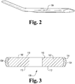
- a first exemplary bone plate 100 includes a non-metallic substrate 102 surrounded by a metallic frame 104.
- the substrate 102 comprises polyether ether ketone (PEEK) and is molded into the shape of a wrist plate for use with fractures of the wrist.
- the frame 104 is fabricated from stainless steel and cupped about its internal perimeter to retain the substrate therein.
- the inner circumferential surface of the metallic frame may be straight, concave, or convex, while the outer circumferential surface of the non-metallic substrate maybe straight, concave, or convex.
- the substrate 102 includes a proximal head portion 106 and a distal shaft portion 108.
- a top and opposed bottom surface 110, 112 of the substrate 102 are joined by a side or edge surface 114.
- the proximal head portion 106 is substantially wider than the distal shaft portion 108 and includes a series of through holes 116 extending from the top surface 110 to the bottom surface 112.
- the distal shaft portion includes its own through holes 120.
- the through holes 116, 120 may be non-threaded and take on a substantially constant circular cross-section along the vertical length of the hole. It should be understood, however, that various shaped through holes 116, 120 may be formed as part of the instant disclosure. For example, the through holes 116, 120 may be threaded. Moreover, the through holes 116, 120 may not include a substantially constant circular cross-section along the vertical length of the hole. An example of a through hole 116, 120 falling within this example would be a bowl-shaped hole where the circular cross-section at the top of the hole (or top surface) is substantially larger that the circular cross-section at the bottom of the hole (or bottom surface).
- through holes 116, 120 have a conical or frustoconical shape.
- the through holes need not be circular in vertical cross-section.
- the holes 116, 120 may be elongated or comprise a series of overlapping circular holes.
- an axis extending through each hole 116, 120 is not required to be perpendicular to either or both of the top and bottom surfaces 110, 112 of the plate 100.
- some of the through holes 116, 120 may be perpendicular with respect to the top or bottom surface 110, 112, while other holes 116, 120 may have axes that are acutely or obtusely angled with respect to the top or bottom surface.
- the holes 116, 120 need not be the same size. Rather certain of the holes 116, 120 may have a circular cross-section with a diameter larger than the diameter of other circular cross-section holes 116, 120. Likewise, some or all of the holes 116 need not have a circular cross-section. Rather, the holes 116, 120 may be elongated in a horizontal direction or take on shapes such as triangular or rectangular. Moreover, some or all of the holes 116, 120 need not have a constant circular cross-section.
- the holes 116, 120 may be slightly deformed by a fastener (e.g., a screw) to provide each fastener in a locked axial orientation that may be different from the original axial orientation of the hole.
- a fastener e.g., a screw
- the metallic frame 104 ensures that no matter how much the substrate 102 is deformed, the overall outline of the bone plate 100 will be retained.
- the metallic frame 104 is deformable to the same or a greater extent than if the entire bone plate had been fabricated from a uniform, metallic substrate.
Landscapes
- Health & Medical Sciences (AREA)
- Orthopedic Medicine & Surgery (AREA)
- Surgery (AREA)
- Life Sciences & Earth Sciences (AREA)
- Heart & Thoracic Surgery (AREA)
- Nuclear Medicine, Radiotherapy & Molecular Imaging (AREA)
- Engineering & Computer Science (AREA)
- Biomedical Technology (AREA)
- Neurology (AREA)
- Medical Informatics (AREA)
- Molecular Biology (AREA)
- Animal Behavior & Ethology (AREA)
- General Health & Medical Sciences (AREA)
- Public Health (AREA)
- Veterinary Medicine (AREA)
- Prostheses (AREA)
- Surgical Instruments (AREA)
Claims (12)
- Verbund-Knochenplatte (100), umfassend:einen starren Ring, der ein starrer Rahmen (104) ist, wobei der Rahmen einen Innenumfang hat, der eine interne Öffnung definiert, und einen Außenumfang, der einen Umriss der Knochenplatte definiert; undein verformbares Material (102), das am starren Rahmen (104) an der internen Öffnung befestigt ist und zumindest teilweise die interne Öffnung überspannt,wobei das verformbare Material (102) mindestens eine Durchgangsöffnung (116, 120) enthält, wobei die Durchgangsöffnung gleichzeitig durch den starren Ring umschrieben wird, derart dass die Durchgangsöffnung vom starren Rahmen (104) umgeben wird,wobei das verformbare Material (102) einen höheren Volumenprozentsatz der Verbundknochenplatte umfasst, als der starre Rahmen (104); undwobei das verformbare Material (102) einen niedrigeren Gewichtsprozentsatz der Verbundknochenplatte umfasst, als der starre Rahmen (104).
- Verbundknochenplatte nach Anspruch 1, wobei das verformbare Material (102) in der Form einer volaren Knochenplatte ist.
- Verbundknochenplatte nach Anspruch 1, wobei
der starre Rahmen (104) auf einer inneren Umfangsfläche konkav ist;
das verformbare Material (102) auf einer äußeren Umfangsfläche konvex ist;
und
die innere Umfangsfläche mindestens einen Teil der äußeren Umfangsfläche kontaktiert. - Verbundknochenplatte nach Anspruch 1, wobei
das verformbare Material (102) auf einer äußeren Umfangsfläche konkav ist;
der starre Rahmen (104) ist auf einer inneren Umfangsfläche konvex; und
die innere Umfangsfläche mindestens einen Teil der äußeren Umfangsfläche kontaktiert. - Verbundknochenplatte nach Anspruch 1, wobei das verformbare Material (102) eine Vielzahl von Durchgangsöffnungen enthält, wobei mindestens eine der Vielzahl von Durchgangsöffnungen (116, 120) einen nicht-gleichförmigen kreisförmigen vertikalen Querschnitt hat.
- Verbundknochenplatten nach Anspruch 1, wobei die Knochenplatte eine implantierbare Knochenplatte ist, und wobei ein oder mehrere Befestigungsmittel sich durch das verformbare Material (102) erstrecken, um die Knochenplatte (100) an Knochen zu befestigen.
- Verbundknochenplatten nach Anspruch 6, wobei die oder jede Durchgangsöffnung in der Lage ist, durch ein Befestigungsmittel verformt zu werden, um jedes Befestigungsmittel in einer verriegelten axialen Orientierung bereitzustellen, die sich von der originalen axialen Orientierung des Loches unterscheiden kann, während der Gesamtumriss der Knochenplatte beibehalten wird.
- Verfahren zum Herstellen einer Verbundknochenplatte, umfassend:Herstellen eines verformbaren Materials (102) in der Form einer Knochenplatte, wobei das verformbare Material (102) eine Vielzahl von Durchgangsöffnungen (116, 120) enthält;Herstellen eines starren Rings, der ein starrer Rahmen (104) ist, wobei der Rahmen einen internen Umfang hat, der eine interne Öffnung definiert, und einen Außenumfang, der einen Umriss der Knochenplatte definiert, wobei die interne Öffnung des starren Rings einen Umriss hat, der der Umrissform des verformbaren Materials (102) folgt; undBefestigen des verformbaren Materials (102) am starren Rahmen (104), derart dass die Vielzahl von Durchgangsöffnungen (116, 120) durch den starren Rahmen (104) umgeben wird.
- Verfahren nach Anspruch 8, wobei der Schritt des Herstellens des verformbaren Materials (102) das Formen des verformbaren Materials (102) in die Form einer volaren Knochenplatte umfasst.
- Verfahren nach Anspruch 8, wobei das verformbare Material (102) Polyetherketon umfasst.
- Verfahren nach Anspruch 8, wobei das verformbare Material (102) in der Form einer volaren Knochenplatte hergestellt wird.
- Verfahren nach Anspruch 8, wobei der Schritt des Befestigens des verformbaren Materials (102) am starren Rahmen (104) mindestens ein Element aus dem Zusammendrücken einer äußeren Umfangsfläche des verformbaren Materials (102) und Ausdehnen einer inneren Umfangsfläche des starren Rahmens (104) umfasst.
Applications Claiming Priority (2)
| Application Number | Priority Date | Filing Date | Title |
|---|---|---|---|
| US13/347,410 US9107718B2 (en) | 2012-01-10 | 2012-01-10 | Bone plate |
| PCT/US2012/055197 WO2013106096A1 (en) | 2012-01-10 | 2012-09-13 | Improved bone plate |
Publications (2)
| Publication Number | Publication Date |
|---|---|
| EP2802277A1 EP2802277A1 (de) | 2014-11-19 |
| EP2802277B1 true EP2802277B1 (de) | 2019-03-20 |
Family
ID=46964053
Family Applications (1)
| Application Number | Title | Priority Date | Filing Date |
|---|---|---|---|
| EP12766787.1A Active EP2802277B1 (de) | 2012-01-10 | 2012-09-13 | Verbesserte knochenplatte |
Country Status (3)
| Country | Link |
|---|---|
| US (1) | US9107718B2 (de) |
| EP (1) | EP2802277B1 (de) |
| WO (1) | WO2013106096A1 (de) |
Families Citing this family (39)
| Publication number | Priority date | Publication date | Assignee | Title |
|---|---|---|---|---|
| WO2013036362A1 (en) | 2011-09-06 | 2013-03-14 | Synthes Usa, Llc | Pancarpal arthrodesis bone plate |
| US9107718B2 (en) | 2012-01-10 | 2015-08-18 | Biomet Manufacturing, Llc | Bone plate |
| FR3030219B1 (fr) * | 2014-12-19 | 2017-02-10 | Biotech Ortho | Plaque de coaptation comportant une ame metallique et un surmoulage en polymere |
| US11197682B2 (en) | 2015-08-27 | 2021-12-14 | Globus Medical, Inc. | Proximal humeral stabilization system |
| US11076898B2 (en) | 2015-08-27 | 2021-08-03 | Globus Medical, Inc. | Proximal humeral stabilization system |
| US10687874B2 (en) | 2015-08-27 | 2020-06-23 | Globus Medical, Inc | Proximal humeral stabilization system |
| US10130402B2 (en) | 2015-09-25 | 2018-11-20 | Globus Medical, Inc. | Bone fixation devices having a locking feature |
| CN108289700A (zh) * | 2015-10-22 | 2018-07-17 | Sim解决医疗创新有限责任公司 | 接骨板以及包括所述接骨板的接骨套件 |
| US9974581B2 (en) | 2015-11-20 | 2018-05-22 | Globus Medical, Inc. | Expandable intramedullary systems and methods of using the same |
| US20170202586A1 (en) * | 2015-12-11 | 2017-07-20 | DePuy Synthes Products, Inc. | Composite implant trial |
| US9795411B2 (en) | 2016-03-02 | 2017-10-24 | Globus Medical, Inc. | Fixators for bone stabilization and associated systems and methods |
| US10531905B2 (en) | 2016-04-19 | 2020-01-14 | Globus Medical, Inc. | Implantable compression screws |
| US10687873B2 (en) | 2016-08-17 | 2020-06-23 | Globus Medical Inc. | Stabilization systems |
| US10420596B2 (en) | 2016-08-17 | 2019-09-24 | Globus Medical, Inc. | Volar distal radius stabilization system |
| US10575884B2 (en) | 2016-08-17 | 2020-03-03 | Globus Medical, Inc. | Fracture plates, systems, and methods |
| US11213327B2 (en) | 2016-08-17 | 2022-01-04 | Globus Medical, Inc. | Fracture plates, systems, and methods |
| US11331128B2 (en) | 2016-08-17 | 2022-05-17 | Globus Medical Inc. | Distal radius stabilization system |
| US11432857B2 (en) | 2016-08-17 | 2022-09-06 | Globus Medical, Inc. | Stabilization systems |
| US11141204B2 (en) | 2016-08-17 | 2021-10-12 | Globus Medical Inc. | Wrist stabilization systems |
| US10751098B2 (en) | 2016-08-17 | 2020-08-25 | Globus Medical Inc. | Stabilization systems |
| US12588937B2 (en) | 2016-08-17 | 2026-03-31 | Globus Medical, Inc. | Volar distal radius stabilization system |
| US11197701B2 (en) | 2016-08-17 | 2021-12-14 | Globus Medical, Inc. | Stabilization systems |
| US10383668B2 (en) | 2016-08-17 | 2019-08-20 | Globus Medical, Inc. | Volar distal radius stabilization system |
| US10299847B2 (en) | 2016-09-22 | 2019-05-28 | Globus Medical, Inc. | Systems and methods for intramedullary nail implantation |
| US10881438B2 (en) | 2017-03-10 | 2021-01-05 | Globus Medical, Inc. | Clavicle fixation system |
| US10368928B2 (en) | 2017-03-13 | 2019-08-06 | Globus Medical, Inc. | Bone stabilization systems |
| US10905477B2 (en) | 2017-03-13 | 2021-02-02 | Globus Medical, Inc. | Bone stabilization systems |
| US11096730B2 (en) | 2017-09-13 | 2021-08-24 | Globus Medical Inc. | Bone stabilization systems |
| US12279795B2 (en) | 2017-09-13 | 2025-04-22 | Globus Medical, Inc. | Bone stabilization systems |
| US10856920B2 (en) | 2017-09-13 | 2020-12-08 | Globus Medical Inc. | Bone stabilization systems |
| US11224468B2 (en) * | 2018-03-02 | 2022-01-18 | Globus Medical, Inc. | Distal tibial plating system |
| US11071570B2 (en) * | 2018-03-02 | 2021-07-27 | Globus Medical, Inc. | Distal tibial plating system |
| US11141172B2 (en) | 2018-04-11 | 2021-10-12 | Globus Medical, Inc. | Method and apparatus for locking a drill guide in a polyaxial hole |
| US11202663B2 (en) | 2019-02-13 | 2021-12-21 | Globus Medical, Inc. | Proximal humeral stabilization systems and methods thereof |
| US12185995B2 (en) | 2019-10-09 | 2025-01-07 | Globus Medical, Inc. | Bone stabilization systems |
| US11129627B2 (en) | 2019-10-30 | 2021-09-28 | Globus Medical, Inc. | Method and apparatus for inserting a bone plate |
| US11723647B2 (en) | 2019-12-17 | 2023-08-15 | Globus Medical, Inc. | Syndesmosis fixation assembly |
| US12064150B2 (en) | 2022-01-19 | 2024-08-20 | Globus Medical Inc. | System and method for treating bone fractures |
| US12478365B2 (en) | 2022-08-24 | 2025-11-25 | Globus Medical, Inc. | Systems, devices and methods for implanting suture buttons |
Family Cites Families (6)
| Publication number | Priority date | Publication date | Assignee | Title |
|---|---|---|---|---|
| US20060247638A1 (en) * | 2005-04-29 | 2006-11-02 | Sdgi Holdings, Inc. | Composite spinal fixation systems |
| US20070225707A1 (en) | 2006-03-22 | 2007-09-27 | Sdgi Holdings, Inc. | Orthopedic spinal devices fabricated from two or more materials |
| US7806911B2 (en) * | 2006-04-14 | 2010-10-05 | Warsaw Orthopedic, Inc. | Fixation plate and method of use |
| DE102006060935A1 (de) | 2006-12-20 | 2008-06-26 | Wolter, Dietmar F., Prof. Dr. | Kraftträger für ein Knochenfixationssystem |
| ES2522925T3 (es) * | 2009-04-08 | 2014-11-19 | Stryker Trauma Sa | Placa ósea híbrida |
| US9107718B2 (en) | 2012-01-10 | 2015-08-18 | Biomet Manufacturing, Llc | Bone plate |
-
2012
- 2012-01-10 US US13/347,410 patent/US9107718B2/en not_active Expired - Fee Related
- 2012-09-13 EP EP12766787.1A patent/EP2802277B1/de active Active
- 2012-09-13 WO PCT/US2012/055197 patent/WO2013106096A1/en not_active Ceased
Non-Patent Citations (1)
| Title |
|---|
| None * |
Also Published As
| Publication number | Publication date |
|---|---|
| US20130178902A1 (en) | 2013-07-11 |
| WO2013106096A1 (en) | 2013-07-18 |
| EP2802277A1 (de) | 2014-11-19 |
| US9107718B2 (en) | 2015-08-18 |
Similar Documents
| Publication | Publication Date | Title |
|---|---|---|
| EP2802277B1 (de) | Verbesserte knochenplatte | |
| US10064737B2 (en) | Implant device for osseous integration | |
| USD857894S1 (en) | Surgical fixation system | |
| EP2840989A1 (de) | Konisch-sphärischer gewindegang für winkelveränderliche schliesssysteme | |
| EP3000423B1 (de) | Knochenplattenarretierungsmechanismus | |
| US20130261675A1 (en) | Loose thread form for variable angle locking systems | |
| WO2018169864A8 (en) | IMPLANT WITH SUPPORTED HELICAL ELEMENTS | |
| US9579210B2 (en) | Talar dome fixation stem | |
| US20120203227A1 (en) | Low profile dorsal plate | |
| US20200214750A1 (en) | Distal radius plate | |
| US10166052B2 (en) | Bone plate with polyaxial locking mechanism | |
| JP2019531867A5 (de) | ||
| WO2009149057A2 (en) | Hybrid orthopedic implant | |
| JP2018051300A (ja) | 掌側遠位橈骨の安定化システム | |
| US20140277141A1 (en) | Pedicle-based construct facet joint fixation device | |
| CN101791201A (zh) | 厨房用多功能砧板 | |
| CA2952967A1 (en) | Locking first metacarpal plate | |
| WO2007047079A3 (en) | Dynamic fixation assemblies with inner core and outer coil-like member | |
| US20140156017A1 (en) | Flex anchor for attaching a prosthesis to bone | |
| KR101277605B1 (ko) | 뼈고정판 및 이의 제조방법 | |
| US20120289978A1 (en) | Retaining mechansim | |
| US10568672B2 (en) | Anatomic osteotomy wedge | |
| JP6847107B2 (ja) | 二重にねじ山を付けられた骨ねじ | |
| EP3116423B1 (de) | Knochenplatte | |
| CN111821070B (zh) | 组合式补骨片及补骨片单元 |
Legal Events
| Date | Code | Title | Description |
|---|---|---|---|
| PUAI | Public reference made under article 153(3) epc to a published international application that has entered the european phase |
Free format text: ORIGINAL CODE: 0009012 |
|
| 17P | Request for examination filed |
Effective date: 20140519 |
|
| AK | Designated contracting states |
Kind code of ref document: A1 Designated state(s): AL AT BE BG CH CY CZ DE DK EE ES FI FR GB GR HR HU IE IS IT LI LT LU LV MC MK MT NL NO PL PT RO RS SE SI SK SM TR |
|
| DAX | Request for extension of the european patent (deleted) | ||
| GRAP | Despatch of communication of intention to grant a patent |
Free format text: ORIGINAL CODE: EPIDOSNIGR1 |
|
| STAA | Information on the status of an ep patent application or granted ep patent |
Free format text: STATUS: GRANT OF PATENT IS INTENDED |
|
| INTG | Intention to grant announced |
Effective date: 20181102 |
|
| GRAS | Grant fee paid |
Free format text: ORIGINAL CODE: EPIDOSNIGR3 |
|
| GRAA | (expected) grant |
Free format text: ORIGINAL CODE: 0009210 |
|
| STAA | Information on the status of an ep patent application or granted ep patent |
Free format text: STATUS: THE PATENT HAS BEEN GRANTED |
|
| AK | Designated contracting states |
Kind code of ref document: B1 Designated state(s): AL AT BE BG CH CY CZ DE DK EE ES FI FR GB GR HR HU IE IS IT LI LT LU LV MC MK MT NL NO PL PT RO RS SE SI SK SM TR |
|
| REG | Reference to a national code |
Ref country code: GB Ref legal event code: FG4D |
|
| REG | Reference to a national code |
Ref country code: CH Ref legal event code: EP |
|
| REG | Reference to a national code |
Ref country code: DE Ref legal event code: R096 Ref document number: 602012058041 Country of ref document: DE |
|
| REG | Reference to a national code |
Ref country code: CH Ref legal event code: NV Representative=s name: VALIPAT S.A. C/O BOVARD SA NEUCHATEL, CH Ref country code: AT Ref legal event code: REF Ref document number: 1109682 Country of ref document: AT Kind code of ref document: T Effective date: 20190415 |
|
| REG | Reference to a national code |
Ref country code: IE Ref legal event code: FG4D |
|
| REG | Reference to a national code |
Ref country code: NL Ref legal event code: MP Effective date: 20190320 |
|
| PG25 | Lapsed in a contracting state [announced via postgrant information from national office to epo] |
Ref country code: FI Free format text: LAPSE BECAUSE OF FAILURE TO SUBMIT A TRANSLATION OF THE DESCRIPTION OR TO PAY THE FEE WITHIN THE PRESCRIBED TIME-LIMIT Effective date: 20190320 Ref country code: SE Free format text: LAPSE BECAUSE OF FAILURE TO SUBMIT A TRANSLATION OF THE DESCRIPTION OR TO PAY THE FEE WITHIN THE PRESCRIBED TIME-LIMIT Effective date: 20190320 Ref country code: NO Free format text: LAPSE BECAUSE OF FAILURE TO SUBMIT A TRANSLATION OF THE DESCRIPTION OR TO PAY THE FEE WITHIN THE PRESCRIBED TIME-LIMIT Effective date: 20190620 Ref country code: LT Free format text: LAPSE BECAUSE OF FAILURE TO SUBMIT A TRANSLATION OF THE DESCRIPTION OR TO PAY THE FEE WITHIN THE PRESCRIBED TIME-LIMIT Effective date: 20190320 |
|
| REG | Reference to a national code |
Ref country code: LT Ref legal event code: MG4D |
|
| PG25 | Lapsed in a contracting state [announced via postgrant information from national office to epo] |
Ref country code: HR Free format text: LAPSE BECAUSE OF FAILURE TO SUBMIT A TRANSLATION OF THE DESCRIPTION OR TO PAY THE FEE WITHIN THE PRESCRIBED TIME-LIMIT Effective date: 20190320 Ref country code: RS Free format text: LAPSE BECAUSE OF FAILURE TO SUBMIT A TRANSLATION OF THE DESCRIPTION OR TO PAY THE FEE WITHIN THE PRESCRIBED TIME-LIMIT Effective date: 20190320 Ref country code: BG Free format text: LAPSE BECAUSE OF FAILURE TO SUBMIT A TRANSLATION OF THE DESCRIPTION OR TO PAY THE FEE WITHIN THE PRESCRIBED TIME-LIMIT Effective date: 20190620 Ref country code: NL Free format text: LAPSE BECAUSE OF FAILURE TO SUBMIT A TRANSLATION OF THE DESCRIPTION OR TO PAY THE FEE WITHIN THE PRESCRIBED TIME-LIMIT Effective date: 20190320 Ref country code: LV Free format text: LAPSE BECAUSE OF FAILURE TO SUBMIT A TRANSLATION OF THE DESCRIPTION OR TO PAY THE FEE WITHIN THE PRESCRIBED TIME-LIMIT Effective date: 20190320 Ref country code: GR Free format text: LAPSE BECAUSE OF FAILURE TO SUBMIT A TRANSLATION OF THE DESCRIPTION OR TO PAY THE FEE WITHIN THE PRESCRIBED TIME-LIMIT Effective date: 20190621 |
|
| REG | Reference to a national code |
Ref country code: AT Ref legal event code: MK05 Ref document number: 1109682 Country of ref document: AT Kind code of ref document: T Effective date: 20190320 |
|
| PG25 | Lapsed in a contracting state [announced via postgrant information from national office to epo] |
Ref country code: SK Free format text: LAPSE BECAUSE OF FAILURE TO SUBMIT A TRANSLATION OF THE DESCRIPTION OR TO PAY THE FEE WITHIN THE PRESCRIBED TIME-LIMIT Effective date: 20190320 Ref country code: RO Free format text: LAPSE BECAUSE OF FAILURE TO SUBMIT A TRANSLATION OF THE DESCRIPTION OR TO PAY THE FEE WITHIN THE PRESCRIBED TIME-LIMIT Effective date: 20190320 Ref country code: IT Free format text: LAPSE BECAUSE OF FAILURE TO SUBMIT A TRANSLATION OF THE DESCRIPTION OR TO PAY THE FEE WITHIN THE PRESCRIBED TIME-LIMIT Effective date: 20190320 Ref country code: EE Free format text: LAPSE BECAUSE OF FAILURE TO SUBMIT A TRANSLATION OF THE DESCRIPTION OR TO PAY THE FEE WITHIN THE PRESCRIBED TIME-LIMIT Effective date: 20190320 Ref country code: AL Free format text: LAPSE BECAUSE OF FAILURE TO SUBMIT A TRANSLATION OF THE DESCRIPTION OR TO PAY THE FEE WITHIN THE PRESCRIBED TIME-LIMIT Effective date: 20190320 Ref country code: ES Free format text: LAPSE BECAUSE OF FAILURE TO SUBMIT A TRANSLATION OF THE DESCRIPTION OR TO PAY THE FEE WITHIN THE PRESCRIBED TIME-LIMIT Effective date: 20190320 Ref country code: PT Free format text: LAPSE BECAUSE OF FAILURE TO SUBMIT A TRANSLATION OF THE DESCRIPTION OR TO PAY THE FEE WITHIN THE PRESCRIBED TIME-LIMIT Effective date: 20190720 Ref country code: CZ Free format text: LAPSE BECAUSE OF FAILURE TO SUBMIT A TRANSLATION OF THE DESCRIPTION OR TO PAY THE FEE WITHIN THE PRESCRIBED TIME-LIMIT Effective date: 20190320 |
|
| PG25 | Lapsed in a contracting state [announced via postgrant information from national office to epo] |
Ref country code: SM Free format text: LAPSE BECAUSE OF FAILURE TO SUBMIT A TRANSLATION OF THE DESCRIPTION OR TO PAY THE FEE WITHIN THE PRESCRIBED TIME-LIMIT Effective date: 20190320 Ref country code: PL Free format text: LAPSE BECAUSE OF FAILURE TO SUBMIT A TRANSLATION OF THE DESCRIPTION OR TO PAY THE FEE WITHIN THE PRESCRIBED TIME-LIMIT Effective date: 20190320 |
|
| PG25 | Lapsed in a contracting state [announced via postgrant information from national office to epo] |
Ref country code: AT Free format text: LAPSE BECAUSE OF FAILURE TO SUBMIT A TRANSLATION OF THE DESCRIPTION OR TO PAY THE FEE WITHIN THE PRESCRIBED TIME-LIMIT Effective date: 20190320 Ref country code: IS Free format text: LAPSE BECAUSE OF FAILURE TO SUBMIT A TRANSLATION OF THE DESCRIPTION OR TO PAY THE FEE WITHIN THE PRESCRIBED TIME-LIMIT Effective date: 20190720 |
|
| REG | Reference to a national code |
Ref country code: DE Ref legal event code: R097 Ref document number: 602012058041 Country of ref document: DE |
|
| PLBE | No opposition filed within time limit |
Free format text: ORIGINAL CODE: 0009261 |
|
| STAA | Information on the status of an ep patent application or granted ep patent |
Free format text: STATUS: NO OPPOSITION FILED WITHIN TIME LIMIT |
|
| PG25 | Lapsed in a contracting state [announced via postgrant information from national office to epo] |
Ref country code: DK Free format text: LAPSE BECAUSE OF FAILURE TO SUBMIT A TRANSLATION OF THE DESCRIPTION OR TO PAY THE FEE WITHIN THE PRESCRIBED TIME-LIMIT Effective date: 20190320 |
|
| 26N | No opposition filed |
Effective date: 20200102 |
|
| PG25 | Lapsed in a contracting state [announced via postgrant information from national office to epo] |
Ref country code: SI Free format text: LAPSE BECAUSE OF FAILURE TO SUBMIT A TRANSLATION OF THE DESCRIPTION OR TO PAY THE FEE WITHIN THE PRESCRIBED TIME-LIMIT Effective date: 20190320 |
|
| PG25 | Lapsed in a contracting state [announced via postgrant information from national office to epo] |
Ref country code: TR Free format text: LAPSE BECAUSE OF FAILURE TO SUBMIT A TRANSLATION OF THE DESCRIPTION OR TO PAY THE FEE WITHIN THE PRESCRIBED TIME-LIMIT Effective date: 20190320 |
|
| PG25 | Lapsed in a contracting state [announced via postgrant information from national office to epo] |
Ref country code: MC Free format text: LAPSE BECAUSE OF FAILURE TO SUBMIT A TRANSLATION OF THE DESCRIPTION OR TO PAY THE FEE WITHIN THE PRESCRIBED TIME-LIMIT Effective date: 20190320 |
|
| PG25 | Lapsed in a contracting state [announced via postgrant information from national office to epo] |
Ref country code: LU Free format text: LAPSE BECAUSE OF NON-PAYMENT OF DUE FEES Effective date: 20190913 |
|
| REG | Reference to a national code |
Ref country code: BE Ref legal event code: MM Effective date: 20190930 |
|
| PG25 | Lapsed in a contracting state [announced via postgrant information from national office to epo] |
Ref country code: BE Free format text: LAPSE BECAUSE OF NON-PAYMENT OF DUE FEES Effective date: 20190930 |
|
| PG25 | Lapsed in a contracting state [announced via postgrant information from national office to epo] |
Ref country code: CY Free format text: LAPSE BECAUSE OF FAILURE TO SUBMIT A TRANSLATION OF THE DESCRIPTION OR TO PAY THE FEE WITHIN THE PRESCRIBED TIME-LIMIT Effective date: 20190320 |
|
| PG25 | Lapsed in a contracting state [announced via postgrant information from national office to epo] |
Ref country code: MT Free format text: LAPSE BECAUSE OF FAILURE TO SUBMIT A TRANSLATION OF THE DESCRIPTION OR TO PAY THE FEE WITHIN THE PRESCRIBED TIME-LIMIT Effective date: 20190320 Ref country code: HU Free format text: LAPSE BECAUSE OF FAILURE TO SUBMIT A TRANSLATION OF THE DESCRIPTION OR TO PAY THE FEE WITHIN THE PRESCRIBED TIME-LIMIT; INVALID AB INITIO Effective date: 20120913 |
|
| PG25 | Lapsed in a contracting state [announced via postgrant information from national office to epo] |
Ref country code: MK Free format text: LAPSE BECAUSE OF FAILURE TO SUBMIT A TRANSLATION OF THE DESCRIPTION OR TO PAY THE FEE WITHIN THE PRESCRIBED TIME-LIMIT Effective date: 20190320 |
|
| P01 | Opt-out of the competence of the unified patent court (upc) registered |
Effective date: 20230526 |
|
| REG | Reference to a national code |
Ref country code: CH Ref legal event code: U11 Free format text: ST27 STATUS EVENT CODE: U-0-0-U10-U11 (AS PROVIDED BY THE NATIONAL OFFICE) Effective date: 20251001 |
|
| PGFP | Annual fee paid to national office [announced via postgrant information from national office to epo] |
Ref country code: DE Payment date: 20250806 Year of fee payment: 14 |
|
| PGFP | Annual fee paid to national office [announced via postgrant information from national office to epo] |
Ref country code: GB Payment date: 20250805 Year of fee payment: 14 |
|
| PGFP | Annual fee paid to national office [announced via postgrant information from national office to epo] |
Ref country code: FR Payment date: 20250807 Year of fee payment: 14 |
|
| PGFP | Annual fee paid to national office [announced via postgrant information from national office to epo] |
Ref country code: IE Payment date: 20250805 Year of fee payment: 14 |
|
| PGFP | Annual fee paid to national office [announced via postgrant information from national office to epo] |
Ref country code: CH Payment date: 20251001 Year of fee payment: 14 |