EP3000423B1 - Knochenplattenarretierungsmechanismus - Google Patents
Knochenplattenarretierungsmechanismus Download PDFInfo
- Publication number
- EP3000423B1 EP3000423B1 EP15002760.5A EP15002760A EP3000423B1 EP 3000423 B1 EP3000423 B1 EP 3000423B1 EP 15002760 A EP15002760 A EP 15002760A EP 3000423 B1 EP3000423 B1 EP 3000423B1
- Authority
- EP
- European Patent Office
- Prior art keywords
- lips
- bone
- bone plate
- bone screw
- screw
- Prior art date
- Legal status (The legal status is an assumption and is not a legal conclusion. Google has not performed a legal analysis and makes no representation as to the accuracy of the status listed.)
- Active
Links
Images




Classifications
-
- A—HUMAN NECESSITIES
- A61—MEDICAL OR VETERINARY SCIENCE; HYGIENE
- A61B—DIAGNOSIS; SURGERY; IDENTIFICATION
- A61B17/00—Surgical instruments, devices or methods
- A61B17/56—Surgical instruments or methods for treatment of bones or joints; Devices specially adapted therefor
- A61B17/58—Surgical instruments or methods for treatment of bones or joints; Devices specially adapted therefor for osteosynthesis, e.g. bone plates, screws or setting implements
- A61B17/68—Internal fixation devices, including fasteners and spinal fixators, even if a part thereof projects from the skin
- A61B17/80—Cortical plates, i.e. bone plates; Instruments for holding or positioning cortical plates, or for compressing bones attached to cortical plates
- A61B17/8033—Cortical plates, i.e. bone plates; Instruments for holding or positioning cortical plates, or for compressing bones attached to cortical plates having indirect contact with screw heads, or having contact with screw heads maintained with the aid of additional components, e.g. nuts, wedges or head covers
- A61B17/8047—Cortical plates, i.e. bone plates; Instruments for holding or positioning cortical plates, or for compressing bones attached to cortical plates having indirect contact with screw heads, or having contact with screw heads maintained with the aid of additional components, e.g. nuts, wedges or head covers wherein the additional element surrounds the screw head in the plate hole
-
- A—HUMAN NECESSITIES
- A61—MEDICAL OR VETERINARY SCIENCE; HYGIENE
- A61B—DIAGNOSIS; SURGERY; IDENTIFICATION
- A61B17/00—Surgical instruments, devices or methods
- A61B17/56—Surgical instruments or methods for treatment of bones or joints; Devices specially adapted therefor
- A61B17/58—Surgical instruments or methods for treatment of bones or joints; Devices specially adapted therefor for osteosynthesis, e.g. bone plates, screws or setting implements
- A61B17/68—Internal fixation devices, including fasteners and spinal fixators, even if a part thereof projects from the skin
- A61B17/80—Cortical plates, i.e. bone plates; Instruments for holding or positioning cortical plates, or for compressing bones attached to cortical plates
- A61B17/8052—Cortical plates, i.e. bone plates; Instruments for holding or positioning cortical plates, or for compressing bones attached to cortical plates immobilised relative to screws by interlocking form of the heads and plate holes, e.g. conical or threaded
Definitions
- the present invention pertains to orthopedic bone plates, and in particular, orthopedic bone plates with screw locking features.
- a common method utilized in repairing fractures of bones includes affixing bone plates to the bone with screws.
- the plates are oriented so that portions thereof are placed on either side of the fracture and screws are placed through bone screw holes of each bone plate portion.
- plates designed for use on the distal and proximal portions of long bones such as the femur or tibia may include a shaft and a head, each with screw holes extending therethrough.
- US 2010/0256686 A1 discloses a bushing which can be inserted into a bone plate hole.
- the bushing includes a plurality of top and bottom tab members.
- the top tab members are spaced around a periphery of the base portion of the bushing and extend in a vertically upward direction toward the top surface of the bone plate. As a screw passes through the bushing, the top tab members flex radially outward to encompass the screw head once the screw moves further.
- US 2014/277180 A1 discloses a variable angle plate comprising an upper surface, a lower surface, and at least one variable angle hole having a cylindrical shape with a continuous thread, the thread comprising six sets of thread peaks and indents that are spaced apart at regular intervals.
- a first aspect of the present invention is a bone plate including the features of claim 1.
- a bone plate may include a body having upper and lower surfaces and a bone screw hole formed through the body and including a plurality of first lips and a plurality of second lips. The first lips are closer to the upper surface than the second lips and the first and second lips are offset around the bone screw hole.
- the bone plate of the first aspect may include a design in which the first and second lips do not overlap each other or partially overlap each other.
- the first and second lips may include ramped surfaces, and the bone screw hole may further include a countersink.
- the bone plate discussed above may be packaged or offered with a bone screw having a head and a shank.
- the bone screw may be of a harder material than bone plate, in particular, the head may be of a harder material than the first and second lips. Placement of the bone screw through the bone plate may result in a deformation or deflection of the first and second lips.
- a second aspect of the present invention is a bone plate system including a body, a bone screw hole formed through the body including a plurality of upper and lower lips and a bone screw having a head and a shank.
- the head may deform or deflect the upper and lower lips upon insertion of the screw through the bone screw hole.
- the upper and lower lips are offset from each other around the bone screw hole, for instance, offset thirty degrees from each other.
- the first and second lips do not overlap each other.
- the first and second lips may partially overlap each other or not overlap each other.
- the first and second lips may include ramped surfaces.
- the bone screw hole may further include a countersink.
- the bone screw may be of a harder material than bone plate, in particular, the head portion.
- Yet another aspect of the present invention is another bone plate system.
- the system according to this aspect includes a body, a bone screw hole formed through the body including a plurality of ramped upper and lower lips and a bone screw having a head and a shank.
- the head is of a harder material than the upper and lower lips and deforms or deflects the upper and lower lips upon insertion of the bone screw in the bone screw hole.
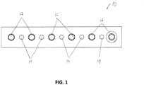
- the present invention is directed to a bone plate 10 that includes a plurality of bone screw holes 12.
- bone plate 10 also includes a series of other holes 14, which may be designed to receive different types of bone screws, k-wires, or the like, or in the case of the plate of Figure 1 , allows for the plate to be fit into a test fixture.
- plate 10 may be designed to cooperate with different anatomical features of the body.
- plate 10 may be designed for placement on the distal radius, and therefore may include a head portion and a shaft portion (not shown).
- the focus of the present invention is on bone screw holes 12, which are to be included in any such plate design. It is to be understood that the plates may include any number of bone screw holes 12, according to their specific intended use.
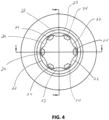
- hole 12 includes a countersink 20, a plurality of upper lips 22 and a plurality of lower lips 24.
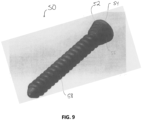
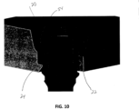
- Countersink 20 is designed, as is shown in Figure 10 , to cooperate with a portion 54 of the head 52 of a bone screw 50, to both facilitate and limit polyaxial movement of the screw with respect to the plate.
- both countersink 20 and portion 54 are curved so as to allow for articulation of the two components with respect to one another through a range of angles, e.g ., up to fifteen degrees in all directions around hole 12.
- the range of allowable polyaxial rotation can vary, including greater and less than the fifteen degrees allowed by the embodiment shown in Figure 10 .
- hole 12 is sized such that shank 58 of screw 50 is able to move a certain distance along with the articulation of head 52 ( e.g ., 15 degrees of rotation).
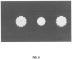
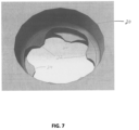
- Upper lips 22 and lower lips 24 are situated circumferentially around hole 12 in an offset manner from one another so that they are not stacked vertically, but rather extend between one another in the axial direction. This is best shown in Figures 2 through 8 .
- the lips are also spaced axially from one another so that there is a space therebetween, which is best shown in Figures 5A and 5B .
- threaded portion 56 of head 52 of screw 50 is ultimately disposed within this space.
- upper lips 22 are arranged at 0°, 60°, 120°, 180°, 240° and 300°, while lower lips 24 are located at 30°, 90°, 150°, 210°, 270° and 360°.
- Figures 7 and 8 depict an embodiment hole 12 that includes four of each of upper lips 22 (situated at 0°, 90°, 180° and 270°) and lower lips 24 (situated at 45°, 135°, 225° and 315°).
- screw 50 may also be placed in hole 12 at a variety of angles, while still achieving the desired function.
- the configuration of lips 22 and 24, as well as the remainder of hole 12 allows for screw 50 to be held in place in a plurality of different angular orientations.
- the angled nature of lips 22 and 24 (best shown in Figures 5A-8 ) not only aids in such placement, but also makes the placement of threaded portion 56 easier to accomplish.
- the lips are effectively ramp-shaped ( i.e ., tapering towards a center of the hole) so as to make passing screw 50 through hole 12 easier.
- the size of shank 58 of screw 50 must be sized to allow for the polyaxial movement of the screw within hole 12.
- plate 10 and screw 50 can be constructed of the same material.
- Upper and lower lips 22, 24 act as somewhat weakened sections, and either deform or deflect upon placement of screw 50 in hole 12.
- threaded section 56 may include threads that are significantly stronger than the thinner lips 22, 24 may facilitate this deformation or deflection.
- the plate may be constructed of a softer material than the screw, thereby further facilitating the deformation and/or deflection of the lips upon placement of the screw.
- the particular embodiment shown depicts a conically threaded head portion 56 of screw 50 which allows for 15° of rotation of the screw with respect to the plate.
- other screw hole/screw shapes/designs can be employed.
Landscapes
- Health & Medical Sciences (AREA)
- Orthopedic Medicine & Surgery (AREA)
- Surgery (AREA)
- Life Sciences & Earth Sciences (AREA)
- Heart & Thoracic Surgery (AREA)
- Nuclear Medicine, Radiotherapy & Molecular Imaging (AREA)
- Engineering & Computer Science (AREA)
- Biomedical Technology (AREA)
- Neurology (AREA)
- Medical Informatics (AREA)
- Molecular Biology (AREA)
- Animal Behavior & Ethology (AREA)
- General Health & Medical Sciences (AREA)
- Public Health (AREA)
- Veterinary Medicine (AREA)
- Surgical Instruments (AREA)
Claims (10)
- Knochenplatte (10), umfassend:einen Körper mit oberen und unteren Oberflächen; undein durch den Körper ausgebildetes Knochenschraubenloch (12), das eine Mehrzahl von ersten Lippen (22) und eine Mehrzahl von zweiten Lippen (24) aufweist, wobei sich die ersten und zweiten Lippen (22, 24) in dem Knochenschraubenloch (12) erstrecken,wobei sich die ersten Lippen (22) näher an der oberen Oberfläche befinden als die zweiten Lippen (24),dadurch gekennzeichnet, dass die ersten und zweiten Lippen (22, 24) in axialer Richtung derart voneinander beabstandet sind, dass in der axialen Richtung jede der Mehrzahl der ersten Lippen (22) in einem gleichen ersten Abstand von der oberen Oberfläche und jede der Mehrzahl der zweiten Lippen (24) in einem gleichen zweiten Abstand von der unteren Oberfläche beabstandet ist, und sich die ersten und zweiten Lippen (22, 24) derart umfänglich versetzt zueinander um das Knochenschraubenloch (12) herum befinden, dass sich die ersten und zweiten Lippen (22, 24) in der axialen Richtung zwischen einander erstrecken und nicht vertikal gestapelt sind.
- Knochenplatte (1) nach Anspruch 1, wobei der Körper eine innere Oberfläche aufweist, die sich zwischen den oberen und unteren Oberflächen erstreckt und das Knochenschraubenloch (12) definiert, wobei sich die ersten und zweiten Lippen (22, 24) von der inneren Oberfläche radial nach innen erstrecken und eine radial innere Kante aufweisen, die von der inneren Oberfläche des Knochenschraubenlochs (12) entfernt ist, sowie sich dazwischen erstreckende Seitenkanten, die konkav sind, um zwischen jeder der Lippen der ersten und zweiten Lippen konkave Senken zu bilden.
- Knochenplatte (10) nach einem der vorangegangenen Ansprüche, wobei die ersten und zweiten Lippen (22, 24) rampenartige Oberflächen aufweisen.
- Knochenplattensystem, umfassend:die Knochenplatte (10) nach einem der Ansprüche 1 bis 3; undeine Knochenschraube (50) mit einem Kopf (52) und einem Schaft (58).
- Knochenplattensystem nach Anspruch 4, wobei der Kopf (52) aus einem härteren Material ist als die ersten und zweiten Lippen (22, 24) und eine Platzierung der Knochenschraube (50) durch die Knochenplatte (10) zu einer Deformation oder Verbiegung der ersten und zweiten Lippen (22, 24) führt.
- Knochenplattensystem nach Anspruch 4, wobei der Kopf (52) dazu ausgebildet ist, die oberen und unteren Lippen (22, 24) zu verformen oder zu verbiegen.
- Knochenplattensystem nach Anspruch 4, wobei die oberen und unteren Lippen (22, 24) um 30 Grad zueinander versetzt sind.
- Knochenplattensystem nach einen der Ansprüche 6 oder 7, wobei die ersten und zweiten Lippen (22, 24) rampenförmige Oberflächen aufweisen.
- Knochenplattensystem nach einem der Ansprüche 6 bis 8, wobei das Knochenplattenloch (12) ferner eine Versenkung (20) aufweist.
- Knochenplattensystem nach einem der Ansprüche 6 bis 9, wobei der Kopf (52) aus einem härteren Material ist als die unteren und oberen Lippen (22, 24).
Applications Claiming Priority (1)
| Application Number | Priority Date | Filing Date | Title |
|---|---|---|---|
| US201462055184P | 2014-09-25 | 2014-09-25 |
Publications (2)
| Publication Number | Publication Date |
|---|---|
| EP3000423A1 EP3000423A1 (de) | 2016-03-30 |
| EP3000423B1 true EP3000423B1 (de) | 2023-07-26 |
Family
ID=54198920
Family Applications (1)
| Application Number | Title | Priority Date | Filing Date |
|---|---|---|---|
| EP15002760.5A Active EP3000423B1 (de) | 2014-09-25 | 2015-09-24 | Knochenplattenarretierungsmechanismus |
Country Status (2)
| Country | Link |
|---|---|
| US (1) | US10258395B2 (de) |
| EP (1) | EP3000423B1 (de) |
Families Citing this family (32)
| Publication number | Priority date | Publication date | Assignee | Title |
|---|---|---|---|---|
| US7951176B2 (en) | 2003-05-30 | 2011-05-31 | Synthes Usa, Llc | Bone plate |
| DE20321552U1 (de) | 2003-08-26 | 2007-12-27 | Synthes Gmbh | Knochenplatte |
| US11259851B2 (en) | 2003-08-26 | 2022-03-01 | DePuy Synthes Products, Inc. | Bone plate |
| US11291484B2 (en) | 2004-01-26 | 2022-04-05 | DePuy Synthes Products, Inc. | Highly-versatile variable-angle bone plate system |
| US8574268B2 (en) | 2004-01-26 | 2013-11-05 | DePuy Synthes Product, LLC | Highly-versatile variable-angle bone plate system |
| EP3082632A4 (de) | 2013-12-20 | 2018-01-10 | Crossroads Extremity Systems, LLC | Polyaxiales verriegelungsloch |
| US11202626B2 (en) | 2014-07-10 | 2021-12-21 | Crossroads Extremity Systems, Llc | Bone implant with means for multi directional force and means of insertion |
| JP2017529886A (ja) | 2014-07-10 | 2017-10-12 | クロスローズ エクストリミティ システムズ リミテッド ライアビリティ カンパニー | 骨インプラントおよび挿入の手段 |
| WO2016057514A1 (en) * | 2014-10-06 | 2016-04-14 | Implantable Design, Llc | Distraction plate system |
| CN107205761A (zh) * | 2014-10-24 | 2017-09-26 | 奥斯托费克斯集团有限公司 | 骨固定系统及其板 |
| CN107847254B (zh) | 2015-07-13 | 2021-06-18 | 汇聚义肢系统有限责任公司 | 具有动态元件的骨板 |
| WO2017096098A1 (en) | 2015-12-01 | 2017-06-08 | Revivo Medical, Llc | Bone fixation apparatus with fastener securement mechanism and methods of use |
| US11197701B2 (en) * | 2016-08-17 | 2021-12-14 | Globus Medical, Inc. | Stabilization systems |
| US10820930B2 (en) | 2016-09-08 | 2020-11-03 | DePuy Synthes Products, Inc. | Variable angle bone plate |
| US10624686B2 (en) | 2016-09-08 | 2020-04-21 | DePuy Synthes Products, Inc. | Variable angel bone plate |
| US10905476B2 (en) | 2016-09-08 | 2021-02-02 | DePuy Synthes Products, Inc. | Variable angle bone plate |
| US11864753B2 (en) | 2017-02-06 | 2024-01-09 | Crossroads Extremity Systems, Llc | Implant inserter |
| WO2018148284A1 (en) | 2017-02-07 | 2018-08-16 | Crossroads Extremity Systems, Llc | Counter-torque implant |
| EP4108194B1 (de) * | 2018-03-02 | 2025-10-29 | Stryker European Operations Limited | Knochenplatten und zugehörige schrauben |
| US11026727B2 (en) | 2018-03-20 | 2021-06-08 | DePuy Synthes Products, Inc. | Bone plate with form-fitting variable-angle locking hole |
| US10772665B2 (en) | 2018-03-29 | 2020-09-15 | DePuy Synthes Products, Inc. | Locking structures for affixing bone anchors to a bone plate, and related systems and methods |
| US11013541B2 (en) | 2018-04-30 | 2021-05-25 | DePuy Synthes Products, Inc. | Threaded locking structures for affixing bone anchors to a bone plate, and related systems and methods |
| US10925651B2 (en) | 2018-12-21 | 2021-02-23 | DePuy Synthes Products, Inc. | Implant having locking holes with collection cavity for shavings |
| ES1227379Y (es) * | 2019-03-06 | 2019-06-21 | Ind Medica Alicantina S L | Dispositivo de fijacion poliaxial |
| WO2020247381A1 (en) * | 2019-06-07 | 2020-12-10 | Smith & Nephew, Inc. | Orthopedic implant with improved variable angle locking mechanism |
| AU2020210308B2 (en) | 2019-08-01 | 2026-01-08 | Howmedica Osteonics Corp. | Multi-stage additive manufacturing process with inserts |
| US10743922B1 (en) | 2019-09-27 | 2020-08-18 | Trilliant Surgical Llc | Variable angle locking construct for orthopedic applications |
| WO2021062102A1 (en) * | 2019-09-27 | 2021-04-01 | Trilliant Surgical Llc | Bone fixation system |
| US12059183B2 (en) | 2020-07-31 | 2024-08-13 | Crossroads Extremity Systems, Llc | Bone plates with dynamic elements and screws |
| USD949341S1 (en) | 2020-09-29 | 2022-04-19 | Trilliant Surgical Llc | Bone fixation plate |
| USD961081S1 (en) | 2020-11-18 | 2022-08-16 | Crossroads Extremity Systems, Llc | Orthopedic implant |
| USD1039152S1 (en) * | 2022-01-18 | 2024-08-13 | Mirus Llc | Bone plate |
Citations (1)
| Publication number | Priority date | Publication date | Assignee | Title |
|---|---|---|---|---|
| US20140277180A1 (en) * | 2013-03-14 | 2014-09-18 | Amei Technologies, Inc. | Variable angle screws, plates and systems |
Family Cites Families (25)
| Publication number | Priority date | Publication date | Assignee | Title |
|---|---|---|---|---|
| DE4343117C2 (de) | 1993-12-17 | 1999-11-04 | Dietmar Wolter | Fixationssystem für Knochen |
| US5601553A (en) | 1994-10-03 | 1997-02-11 | Synthes (U.S.A.) | Locking plate and bone screw |
| DE59509247D1 (de) | 1995-09-06 | 2001-06-13 | Synthes Ag | Knochenplatte |
| EP0909143A4 (de) | 1996-06-14 | 2008-11-26 | Depuy Ace Medical Company | Knochenplatte für obere extremitäten |
| DE19629011C2 (de) | 1996-07-18 | 2001-08-23 | Dietmar Wolter | Hilfsmittel für die Osteosynthese |
| DE19858889B4 (de) | 1998-12-19 | 2008-08-07 | Wolter, Dietmar, Prof. Dr.Med. | Fixationssystem für Knochen |
| US6730091B1 (en) | 1999-05-03 | 2004-05-04 | Medartis Ag | Blockable bone plate |
| DE19962317A1 (de) | 1999-09-14 | 2001-03-15 | Dietmar Wolter | Fixationssystem für Knochen |
| DE50011463D1 (de) | 1999-09-14 | 2005-12-01 | Wolter Dietmar | Fixationssystem für knochen |
| US7179260B2 (en) | 2003-09-29 | 2007-02-20 | Smith & Nephew, Inc. | Bone plates and bone plate assemblies |
| US6955677B2 (en) | 2002-10-15 | 2005-10-18 | The University Of North Carolina At Chapel Hill | Multi-angular fastening apparatus and method for surgical bone screw/plate systems |
| US7722653B2 (en) | 2003-03-26 | 2010-05-25 | Greatbatch Medical S.A. | Locking bone plate |
| US8105367B2 (en) | 2003-09-29 | 2012-01-31 | Smith & Nephew, Inc. | Bone plate and bone plate assemblies including polyaxial fasteners |
| US7637928B2 (en) * | 2004-01-26 | 2009-12-29 | Synthes Usa, Llc | Variable angle locked bone fixation system |
| DE102004035546A1 (de) | 2004-07-19 | 2006-02-16 | Wolter, Dietmar, Prof. Dr.Med. | Fixationssystem für Knochen und Füllkörper für ein Fixationssystem für Knochen |
| EP1649819A1 (de) | 2004-10-19 | 2006-04-26 | Christian Maier | Knochenplatte |
| EP1919385B1 (de) * | 2005-07-25 | 2014-08-20 | Smith & Nephew, Inc. | Polyaxiale platten |
| US8382807B2 (en) | 2005-07-25 | 2013-02-26 | Smith & Nephew, Inc. | Systems and methods for using polyaxial plates |
| JP2010512981A (ja) | 2006-12-19 | 2010-04-30 | スモール・ボーン・イノベーションズ・インコーポレーテッド | ロッキング固定システムおよびラグ工具 |
| US8870931B2 (en) * | 2007-03-21 | 2014-10-28 | The University Of North Carolina At Chapel Hill | Anti-unscrewing and multi-angular fastening apparatuses and methods for surgical bone screw/plate systems |
| US20090048605A1 (en) | 2007-08-14 | 2009-02-19 | Anglefix Tech, Llc | Surgical lag tool devices and methods for use with surgical bone screw/plate systems |
| US8211154B2 (en) * | 2009-04-06 | 2012-07-03 | Lanx, Inc. | Bone plate assemblies with backout protection and visual indicator |
| CN103717179B (zh) | 2011-06-15 | 2017-08-08 | 史密夫和内修有限公司 | 可变角度锁定植入物 |
| DE102011051975B4 (de) * | 2011-07-20 | 2023-01-12 | Ulrich Gmbh & Co. Kg | Implantat |
| ES2696048T3 (es) | 2011-09-12 | 2019-01-11 | Dietmar Wolter | Placa de osteosíntesis |
-
2015
- 2015-09-24 EP EP15002760.5A patent/EP3000423B1/de active Active
- 2015-09-24 US US14/863,926 patent/US10258395B2/en active Active
Patent Citations (1)
| Publication number | Priority date | Publication date | Assignee | Title |
|---|---|---|---|---|
| US20140277180A1 (en) * | 2013-03-14 | 2014-09-18 | Amei Technologies, Inc. | Variable angle screws, plates and systems |
Also Published As
| Publication number | Publication date |
|---|---|
| EP3000423A1 (de) | 2016-03-30 |
| US10258395B2 (en) | 2019-04-16 |
| US20160089191A1 (en) | 2016-03-31 |
Similar Documents
| Publication | Publication Date | Title |
|---|---|---|
| EP3000423B1 (de) | Knochenplattenarretierungsmechanismus | |
| EP3701894A1 (de) | Knochenplatten und zugehörige schrauben | |
| EP3033018B1 (de) | Polyaxiale fixierungsvorrichtung | |
| US9414875B2 (en) | Dynamic bone fixation element and method of using the same | |
| ES2427981T3 (es) | Implante para fijación ósea | |
| EP2364657B1 (de) | Système de fixation osseuse avec fils profilés incurvés | |
| US8366751B2 (en) | Bone plate having elevations permitting countersinking of bone screws | |
| US9277947B2 (en) | Variable angle bone fixation device | |
| US9320552B2 (en) | Passive screw locking mechanism | |
| JP6698097B2 (ja) | 骨固定装置 | |
| JP6847096B2 (ja) | 骨固定用インプラントシステム | |
| US20200038075A1 (en) | Modular spinal fixation device | |
| BR112015003749B1 (pt) | Sistema de fixação óssea | |
| EP2789303A1 (de) | Implantierbare Einsetzhülse | |
| US20130310881A1 (en) | Anti-backout mechanism for orthopedic devices | |
| US20160095639A1 (en) | Washer assembly for spinal fixation screw | |
| US10751100B2 (en) | Bone screws and surgical sets comprising bone screws | |
| ES2752456T3 (es) | Tapa de extremo cónica para clavo intramedular | |
| US20170079692A1 (en) | Osteosynthesis Assembly Formed by a Plate and at Least One Screw | |
| CN105078556A (zh) | 一种防止骨螺钉退出的脊柱钉板结构 |
Legal Events
| Date | Code | Title | Description |
|---|---|---|---|
| PUAI | Public reference made under article 153(3) epc to a published international application that has entered the european phase |
Free format text: ORIGINAL CODE: 0009012 |
|
| AK | Designated contracting states |
Kind code of ref document: A1 Designated state(s): AL AT BE BG CH CY CZ DE DK EE ES FI FR GB GR HR HU IE IS IT LI LT LU LV MC MK MT NL NO PL PT RO RS SE SI SK SM TR |
|
| AX | Request for extension of the european patent |
Extension state: BA ME |
|
| 17P | Request for examination filed |
Effective date: 20160811 |
|
| STAA | Information on the status of an ep patent application or granted ep patent |
Free format text: STATUS: EXAMINATION IS IN PROGRESS |
|
| 17Q | First examination report despatched |
Effective date: 20190301 |
|
| RAP1 | Party data changed (applicant data changed or rights of an application transferred) |
Owner name: STRYKER EUROPEAN OPERATIONS HOLDINGS LLC |
|
| GRAP | Despatch of communication of intention to grant a patent |
Free format text: ORIGINAL CODE: EPIDOSNIGR1 |
|
| STAA | Information on the status of an ep patent application or granted ep patent |
Free format text: STATUS: GRANT OF PATENT IS INTENDED |
|
| INTG | Intention to grant announced |
Effective date: 20230227 |
|
| GRAS | Grant fee paid |
Free format text: ORIGINAL CODE: EPIDOSNIGR3 |
|
| GRAA | (expected) grant |
Free format text: ORIGINAL CODE: 0009210 |
|
| STAA | Information on the status of an ep patent application or granted ep patent |
Free format text: STATUS: THE PATENT HAS BEEN GRANTED |
|
| P01 | Opt-out of the competence of the unified patent court (upc) registered |
Effective date: 20230529 |
|
| AK | Designated contracting states |
Kind code of ref document: B1 Designated state(s): AL AT BE BG CH CY CZ DE DK EE ES FI FR GB GR HR HU IE IS IT LI LT LU LV MC MK MT NL NO PL PT RO RS SE SI SK SM TR |
|
| REG | Reference to a national code |
Ref country code: DE Ref legal event code: R082 Ref document number: 602015084729 Country of ref document: DE Representative=s name: WUESTHOFF & WUESTHOFF, PATENTANWAELTE PARTG MB, DE Ref country code: DE Ref legal event code: R082 Ref document number: 602015084729 Country of ref document: DE Representative=s name: WUESTHOFF & WUESTHOFF PATENTANWAELTE UND RECHT, DE |
|
| REG | Reference to a national code |
Ref country code: DE Ref legal event code: R082 Ref document number: 602015084729 Country of ref document: DE Representative=s name: WUESTHOFF & WUESTHOFF, PATENTANWAELTE PARTG MB, DE Ref country code: CH Ref legal event code: EP Ref country code: DE Ref legal event code: R082 Ref document number: 602015084729 Country of ref document: DE Representative=s name: WUESTHOFF & WUESTHOFF PATENTANWAELTE UND RECHT, DE |
|
| REG | Reference to a national code |
Ref country code: IE Ref legal event code: FG4D |
|
| REG | Reference to a national code |
Ref country code: DE Ref legal event code: R096 Ref document number: 602015084729 Country of ref document: DE |
|
| REG | Reference to a national code |
Ref country code: LT Ref legal event code: MG9D |
|
| REG | Reference to a national code |
Ref country code: NL Ref legal event code: MP Effective date: 20230726 |
|
| REG | Reference to a national code |
Ref country code: AT Ref legal event code: MK05 Ref document number: 1591031 Country of ref document: AT Kind code of ref document: T Effective date: 20230726 |
|
| PG25 | Lapsed in a contracting state [announced via postgrant information from national office to epo] |
Ref country code: NL Free format text: LAPSE BECAUSE OF FAILURE TO SUBMIT A TRANSLATION OF THE DESCRIPTION OR TO PAY THE FEE WITHIN THE PRESCRIBED TIME-LIMIT Effective date: 20230726 |
|
| PG25 | Lapsed in a contracting state [announced via postgrant information from national office to epo] |
Ref country code: GR Free format text: LAPSE BECAUSE OF FAILURE TO SUBMIT A TRANSLATION OF THE DESCRIPTION OR TO PAY THE FEE WITHIN THE PRESCRIBED TIME-LIMIT Effective date: 20231027 |
|
| PG25 | Lapsed in a contracting state [announced via postgrant information from national office to epo] |
Ref country code: IS Free format text: LAPSE BECAUSE OF FAILURE TO SUBMIT A TRANSLATION OF THE DESCRIPTION OR TO PAY THE FEE WITHIN THE PRESCRIBED TIME-LIMIT Effective date: 20231126 |
|
| PG25 | Lapsed in a contracting state [announced via postgrant information from national office to epo] |
Ref country code: SE Free format text: LAPSE BECAUSE OF FAILURE TO SUBMIT A TRANSLATION OF THE DESCRIPTION OR TO PAY THE FEE WITHIN THE PRESCRIBED TIME-LIMIT Effective date: 20230726 Ref country code: RS Free format text: LAPSE BECAUSE OF FAILURE TO SUBMIT A TRANSLATION OF THE DESCRIPTION OR TO PAY THE FEE WITHIN THE PRESCRIBED TIME-LIMIT Effective date: 20230726 Ref country code: PT Free format text: LAPSE BECAUSE OF FAILURE TO SUBMIT A TRANSLATION OF THE DESCRIPTION OR TO PAY THE FEE WITHIN THE PRESCRIBED TIME-LIMIT Effective date: 20231127 Ref country code: NO Free format text: LAPSE BECAUSE OF FAILURE TO SUBMIT A TRANSLATION OF THE DESCRIPTION OR TO PAY THE FEE WITHIN THE PRESCRIBED TIME-LIMIT Effective date: 20231026 Ref country code: LV Free format text: LAPSE BECAUSE OF FAILURE TO SUBMIT A TRANSLATION OF THE DESCRIPTION OR TO PAY THE FEE WITHIN THE PRESCRIBED TIME-LIMIT Effective date: 20230726 Ref country code: LT Free format text: LAPSE BECAUSE OF FAILURE TO SUBMIT A TRANSLATION OF THE DESCRIPTION OR TO PAY THE FEE WITHIN THE PRESCRIBED TIME-LIMIT Effective date: 20230726 Ref country code: IS Free format text: LAPSE BECAUSE OF FAILURE TO SUBMIT A TRANSLATION OF THE DESCRIPTION OR TO PAY THE FEE WITHIN THE PRESCRIBED TIME-LIMIT Effective date: 20231126 Ref country code: HR Free format text: LAPSE BECAUSE OF FAILURE TO SUBMIT A TRANSLATION OF THE DESCRIPTION OR TO PAY THE FEE WITHIN THE PRESCRIBED TIME-LIMIT Effective date: 20230726 Ref country code: GR Free format text: LAPSE BECAUSE OF FAILURE TO SUBMIT A TRANSLATION OF THE DESCRIPTION OR TO PAY THE FEE WITHIN THE PRESCRIBED TIME-LIMIT Effective date: 20231027 Ref country code: FI Free format text: LAPSE BECAUSE OF FAILURE TO SUBMIT A TRANSLATION OF THE DESCRIPTION OR TO PAY THE FEE WITHIN THE PRESCRIBED TIME-LIMIT Effective date: 20230726 Ref country code: AT Free format text: LAPSE BECAUSE OF FAILURE TO SUBMIT A TRANSLATION OF THE DESCRIPTION OR TO PAY THE FEE WITHIN THE PRESCRIBED TIME-LIMIT Effective date: 20230726 |
|
| PG25 | Lapsed in a contracting state [announced via postgrant information from national office to epo] |
Ref country code: PL Free format text: LAPSE BECAUSE OF FAILURE TO SUBMIT A TRANSLATION OF THE DESCRIPTION OR TO PAY THE FEE WITHIN THE PRESCRIBED TIME-LIMIT Effective date: 20230726 |
|
| PG25 | Lapsed in a contracting state [announced via postgrant information from national office to epo] |
Ref country code: ES Free format text: LAPSE BECAUSE OF FAILURE TO SUBMIT A TRANSLATION OF THE DESCRIPTION OR TO PAY THE FEE WITHIN THE PRESCRIBED TIME-LIMIT Effective date: 20230726 |
|
| REG | Reference to a national code |
Ref country code: DE Ref legal event code: R097 Ref document number: 602015084729 Country of ref document: DE |
|
| PG25 | Lapsed in a contracting state [announced via postgrant information from national office to epo] |
Ref country code: SM Free format text: LAPSE BECAUSE OF FAILURE TO SUBMIT A TRANSLATION OF THE DESCRIPTION OR TO PAY THE FEE WITHIN THE PRESCRIBED TIME-LIMIT Effective date: 20230726 Ref country code: RO Free format text: LAPSE BECAUSE OF FAILURE TO SUBMIT A TRANSLATION OF THE DESCRIPTION OR TO PAY THE FEE WITHIN THE PRESCRIBED TIME-LIMIT Effective date: 20230726 Ref country code: ES Free format text: LAPSE BECAUSE OF FAILURE TO SUBMIT A TRANSLATION OF THE DESCRIPTION OR TO PAY THE FEE WITHIN THE PRESCRIBED TIME-LIMIT Effective date: 20230726 Ref country code: EE Free format text: LAPSE BECAUSE OF FAILURE TO SUBMIT A TRANSLATION OF THE DESCRIPTION OR TO PAY THE FEE WITHIN THE PRESCRIBED TIME-LIMIT Effective date: 20230726 Ref country code: DK Free format text: LAPSE BECAUSE OF FAILURE TO SUBMIT A TRANSLATION OF THE DESCRIPTION OR TO PAY THE FEE WITHIN THE PRESCRIBED TIME-LIMIT Effective date: 20230726 Ref country code: CZ Free format text: LAPSE BECAUSE OF FAILURE TO SUBMIT A TRANSLATION OF THE DESCRIPTION OR TO PAY THE FEE WITHIN THE PRESCRIBED TIME-LIMIT Effective date: 20230726 Ref country code: SK Free format text: LAPSE BECAUSE OF FAILURE TO SUBMIT A TRANSLATION OF THE DESCRIPTION OR TO PAY THE FEE WITHIN THE PRESCRIBED TIME-LIMIT Effective date: 20230726 |
|
| PG25 | Lapsed in a contracting state [announced via postgrant information from national office to epo] |
Ref country code: LU Free format text: LAPSE BECAUSE OF NON-PAYMENT OF DUE FEES Effective date: 20230924 |
|
| REG | Reference to a national code |
Ref country code: BE Ref legal event code: MM Effective date: 20230930 |
|
| PG25 | Lapsed in a contracting state [announced via postgrant information from national office to epo] |
Ref country code: LU Free format text: LAPSE BECAUSE OF NON-PAYMENT OF DUE FEES Effective date: 20230924 Ref country code: IT Free format text: LAPSE BECAUSE OF FAILURE TO SUBMIT A TRANSLATION OF THE DESCRIPTION OR TO PAY THE FEE WITHIN THE PRESCRIBED TIME-LIMIT Effective date: 20230726 Ref country code: MC Free format text: LAPSE BECAUSE OF FAILURE TO SUBMIT A TRANSLATION OF THE DESCRIPTION OR TO PAY THE FEE WITHIN THE PRESCRIBED TIME-LIMIT Effective date: 20230726 |
|
| PLBE | No opposition filed within time limit |
Free format text: ORIGINAL CODE: 0009261 |
|
| STAA | Information on the status of an ep patent application or granted ep patent |
Free format text: STATUS: NO OPPOSITION FILED WITHIN TIME LIMIT |
|
| 26N | No opposition filed |
Effective date: 20240429 |
|
| REG | Reference to a national code |
Ref country code: IE Ref legal event code: MM4A |
|
| PG25 | Lapsed in a contracting state [announced via postgrant information from national office to epo] |
Ref country code: IE Free format text: LAPSE BECAUSE OF NON-PAYMENT OF DUE FEES Effective date: 20230924 |
|
| PG25 | Lapsed in a contracting state [announced via postgrant information from national office to epo] |
Ref country code: IE Free format text: LAPSE BECAUSE OF NON-PAYMENT OF DUE FEES Effective date: 20230924 Ref country code: SI Free format text: LAPSE BECAUSE OF FAILURE TO SUBMIT A TRANSLATION OF THE DESCRIPTION OR TO PAY THE FEE WITHIN THE PRESCRIBED TIME-LIMIT Effective date: 20230726 |
|
| PG25 | Lapsed in a contracting state [announced via postgrant information from national office to epo] |
Ref country code: BE Free format text: LAPSE BECAUSE OF NON-PAYMENT OF DUE FEES Effective date: 20230930 |
|
| PG25 | Lapsed in a contracting state [announced via postgrant information from national office to epo] |
Ref country code: BG Free format text: LAPSE BECAUSE OF FAILURE TO SUBMIT A TRANSLATION OF THE DESCRIPTION OR TO PAY THE FEE WITHIN THE PRESCRIBED TIME-LIMIT Effective date: 20230726 |
|
| PG25 | Lapsed in a contracting state [announced via postgrant information from national office to epo] |
Ref country code: BG Free format text: LAPSE BECAUSE OF FAILURE TO SUBMIT A TRANSLATION OF THE DESCRIPTION OR TO PAY THE FEE WITHIN THE PRESCRIBED TIME-LIMIT Effective date: 20230726 |
|
| PG25 | Lapsed in a contracting state [announced via postgrant information from national office to epo] |
Ref country code: CY Free format text: LAPSE BECAUSE OF FAILURE TO SUBMIT A TRANSLATION OF THE DESCRIPTION OR TO PAY THE FEE WITHIN THE PRESCRIBED TIME-LIMIT; INVALID AB INITIO Effective date: 20150924 |
|
| PG25 | Lapsed in a contracting state [announced via postgrant information from national office to epo] |
Ref country code: HU Free format text: LAPSE BECAUSE OF FAILURE TO SUBMIT A TRANSLATION OF THE DESCRIPTION OR TO PAY THE FEE WITHIN THE PRESCRIBED TIME-LIMIT; INVALID AB INITIO Effective date: 20150924 |
|
| REG | Reference to a national code |
Ref country code: CH Ref legal event code: U11 Free format text: ST27 STATUS EVENT CODE: U-0-0-U10-U11 (AS PROVIDED BY THE NATIONAL OFFICE) Effective date: 20251001 |
|
| PGFP | Annual fee paid to national office [announced via postgrant information from national office to epo] |
Ref country code: DE Payment date: 20250702 Year of fee payment: 11 |
|
| PGFP | Annual fee paid to national office [announced via postgrant information from national office to epo] |
Ref country code: GB Payment date: 20250703 Year of fee payment: 11 |
|
| PGFP | Annual fee paid to national office [announced via postgrant information from national office to epo] |
Ref country code: FR Payment date: 20250808 Year of fee payment: 11 |
|
| PG25 | Lapsed in a contracting state [announced via postgrant information from national office to epo] |
Ref country code: TR Free format text: LAPSE BECAUSE OF FAILURE TO SUBMIT A TRANSLATION OF THE DESCRIPTION OR TO PAY THE FEE WITHIN THE PRESCRIBED TIME-LIMIT Effective date: 20230726 |
|
| PGFP | Annual fee paid to national office [announced via postgrant information from national office to epo] |
Ref country code: CH Payment date: 20251001 Year of fee payment: 11 |