EP2802048B1 - Schutzschlauch mit elektromagnetischer Abschirmung - Google Patents
Schutzschlauch mit elektromagnetischer Abschirmung Download PDFInfo
- Publication number
- EP2802048B1 EP2802048B1 EP14166972.1A EP14166972A EP2802048B1 EP 2802048 B1 EP2802048 B1 EP 2802048B1 EP 14166972 A EP14166972 A EP 14166972A EP 2802048 B1 EP2802048 B1 EP 2802048B1
- Authority
- EP
- European Patent Office
- Prior art keywords
- threads
- protective
- hose
- protective hose
- shielding
- Prior art date
- Legal status (The legal status is an assumption and is not a legal conclusion. Google has not performed a legal analysis and makes no representation as to the accuracy of the status listed.)
- Active
Links
Images
Classifications
-
- H—ELECTRICITY
- H02—GENERATION; CONVERSION OR DISTRIBUTION OF ELECTRIC POWER
- H02G—INSTALLATION OF ELECTRIC CABLES OR LINES, OR OF COMBINED OPTICAL AND ELECTRIC CABLES OR LINES
- H02G3/00—Installations of electric cables or lines or protective tubing therefor in or on buildings, equivalent structures or vehicles
- H02G3/02—Details
- H02G3/04—Protective tubing or conduits, e.g. cable ladders or cable troughs
- H02G3/0462—Tubings, i.e. having a closed section
- H02G3/0481—Tubings, i.e. having a closed section with a circular cross-section
-
- D—TEXTILES; PAPER
- D04—BRAIDING; LACE-MAKING; KNITTING; TRIMMINGS; NON-WOVEN FABRICS
- D04B—KNITTING
- D04B1/00—Weft knitting processes for the production of fabrics or articles not dependent on the use of particular machines; Fabrics or articles defined by such processes
- D04B1/14—Other fabrics or articles characterised primarily by the use of particular thread materials
-
- D—TEXTILES; PAPER
- D04—BRAIDING; LACE-MAKING; KNITTING; TRIMMINGS; NON-WOVEN FABRICS
- D04C—BRAIDING OR MANUFACTURE OF LACE, INCLUDING BOBBIN-NET OR CARBONISED LACE; BRAIDING MACHINES; BRAID; LACE
- D04C1/00—Braid or lace, e.g. pillow-lace; Processes for the manufacture thereof
- D04C1/02—Braid or lace, e.g. pillow-lace; Processes for the manufacture thereof made from particular materials
-
- H—ELECTRICITY
- H05—ELECTRIC TECHNIQUES NOT OTHERWISE PROVIDED FOR
- H05K—PRINTED CIRCUITS; CASINGS OR CONSTRUCTIONAL DETAILS OF ELECTRIC APPARATUS; MANUFACTURE OF ASSEMBLAGES OF ELECTRICAL COMPONENTS
- H05K9/00—Screening of apparatus or components against electric or magnetic fields
- H05K9/0073—Shielding materials
- H05K9/0098—Shielding materials for shielding electrical cables
-
- D—TEXTILES; PAPER
- D10—INDEXING SCHEME ASSOCIATED WITH SUBLASSES OF SECTION D, RELATING TO TEXTILES
- D10B—INDEXING SCHEME ASSOCIATED WITH SUBLASSES OF SECTION D, RELATING TO TEXTILES
- D10B2101/00—Inorganic fibres
- D10B2101/20—Metallic fibres
-
- D—TEXTILES; PAPER
- D10—INDEXING SCHEME ASSOCIATED WITH SUBLASSES OF SECTION D, RELATING TO TEXTILES
- D10B—INDEXING SCHEME ASSOCIATED WITH SUBLASSES OF SECTION D, RELATING TO TEXTILES
- D10B2401/00—Physical properties
- D10B2401/16—Physical properties antistatic; conductive
-
- D—TEXTILES; PAPER
- D10—INDEXING SCHEME ASSOCIATED WITH SUBLASSES OF SECTION D, RELATING TO TEXTILES
- D10B—INDEXING SCHEME ASSOCIATED WITH SUBLASSES OF SECTION D, RELATING TO TEXTILES
- D10B2505/00—Industrial
- D10B2505/12—Vehicles
Definitions
- the invention relates to a protective hose whose diameter can be elastically expanded according to the preamble of claim 1.
- Such protective conduits are used, for example, to protect electrical cables from the influence of electromagnetic interference.
- One area of application is automotive engineering, particularly vehicle wiring.
- the protective conduit must be pulled over a connector that is not detachably connected to the electrical line or cable.
- the resilience of the protective conduit i.e., its ability to shrink back to a diameter adapted to the diameter of the line or cable after passing through the connector.
- a protective hose is, for example, made of EP 1 348 247 B1
- the known protective hose is designed as a braided hose, in which, in addition to the threads made of electrically conductive material, plastic threads are also used, which ensure the protective hose's elastic recovery after expansion.
- plastic threads are also used, which ensure the protective hose's elastic recovery after expansion.
- the known protective hose has a lower shielding capacity against electromagnetic interference in lengths where it remains expanded when installed, for example, in a length directly adjacent to a connector, than in lengths where it has been able to fully contract.
- the document WO-A-03013208 a network known which is a first and a second group of fibers, each arranged in a first and second direction.
- One of the two groups of fibers is wrapped with a metal foil, so that the braid can exhibit electromagnetic shielding properties. Due to the arrangement of the fibers or groups of fibers, the braid also exhibits elastic properties.
- the protective sheath which has electromagnetic shielding properties.
- the protective sheath comprises a magnetic and a conductive layer.
- the magnetic layer is composed of a mix of elastomer and magnetic powder.
- the protective sheath disclosed herein is slit on one side parallel to its longitudinal axis.
- a protective hose with electromagnetic shielding is known into which cables to be insulated can be inserted, or which can be knitted and/or braided around cables to be insulated.
- a protective hose according to claim 1 This object is achieved according to the invention by a protective hose according to claim 1.
- the sheath made of the elastically stretchable material This ensures that the threads from which the protective sleeve is made remain reliably in contact with each other at the points where they touch each other during expansion, so that the eddy currents induced by electromagnetic interference can circulate essentially unhindered, regardless of the expanded state of the protective sleeve, and thus can exert their shielding effect essentially unhindered.
- EMC test EMC - electromagnetic compatibility
- Silicone for example, can be used as an elastically stretchable material.
- polyurethane, polyurethane-based materials, natural rubber, or elastomers in general are also possible.
- a silicone for example, available under the trade name Elastosil® LR 3003/20 from Wacker Chemie AG, can be used.
- the protective hose is a braided protective hose.
- a knitted protective hose (not according to the invention) for such a use will also be described as an example.
- a flat braiding angle i.e., a braiding angle measured relative to the longitudinal direction of the protective tube of less than 45°, preferably less than 30°, is provided.
- the expandability can be achieved by keeping the knitted fabric under tension in the longitudinal direction of the protective tube while covering it with the elastically stretchable material, so that the stitches of the knitted fabric are stretched.
- the stretched shape of the stitches can be virtually "frozen” by the elastically stretchable sheathing.
- the stitch sections running in the longitudinal direction of the protective tube run essentially parallel to one another.
- the tube can be expanded without the stitches shifting relative to one another, because the sheathing fixes the thread sections touching each other at the stitch points.
- the invention provides that, in the non-expanded state of the protective tube, the ratio of the length of the mesh sections running in the longitudinal direction of the protective tube to the length of the mesh sections running in the circumferential direction of the protective tube is at least 2. Preferably, this ratio can be at least 3, more preferably at least 5.
- At least one of the threads comprises a plurality of fibers, of which at least some, preferably all, are made of electrically conductive material.
- the provision of a plurality of fibers of electrically conductive material per thread has the advantage that the fibers of two Arrange adjacent threads in such a way that both threads have a flattened cross-sectional area. This increases the number of fibers in contact, which in turn has a positive effect on the circulation of eddy currents induced by electromagnetic interference and thus on the shielding effect.
- the fibers are preferably arranged next to one another due to their flattening. If all fibers of all threads are made of electrically conductive material, the best possible shielding effect is also achieved.
- the sheathing made of the elastically stretchable material ensures that the fibers of the threads cannot cluster together when the protective tube is expanded, but that the juxtaposition of the fibers of the threads and thus the quality of the shielding effect is maintained.
- fibers with a circular disk-shaped cross-sectional area fibers with a flattened cross-section can also be used to improve the shielding effect.
- a fiber made of an electrically conductive material can also be referred to as a "wire.”
- the term “fiber” will nevertheless be used.
- At least one thread, preferably each thread, and/or at least one fiber, preferably each fiber is/are made of copper, preferably tinned or silvered copper. Copper is advantageous because of its high conductivity. Tinning can also improve the corrosion resistance and/or solderability of the protective tube. However, for high conductivity, the copper fibers can also be silvered.
- the tear extensibility of the elastically extensible Material is more than 200%, preferably more than 500%, and even more preferably at least 800%.
- the "tear-extensibility" is determined by stretching a material strip of a predetermined length until it tears. The length of the material strip immediately before it tears, divided by the predetermined length, results in a dimensionless value referred to as "tear-extensibility.”
- the value of the tear-extensibility of the elastically stretchable material can be selected depending on the extensibility of the protective sleeve, in particular the braided or knitted fabric.
- the protective hose has, on the one hand, very good recovery properties when expanded, since the sheathing contracts again over its entire surface after expansion.
- the perforation-free sheathing can also provide protection against moisture.
- a perforation-free sheathing ensures uniform expansion of the protective hose.
- the protective hose to be colored throughout. Such continuous coloring, particularly in signal orange, is required, for example, in electric and hybrid vehicles for the cables carrying the drive current.
- the sheath adheres to the threads at least on the side facing the outer peripheral surface of the hose.
- Complete embedding of the threads or fibers in the elastically stretchable material is not necessary. Rather, it is sufficient to bond the threads or fibers together in such a way that they remain in contact with each other when the protective hose expands. This can also be done only from the outside of the threads or fibers.
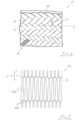
- FIG 1 is a protective hose designed as a braided hose, generally designated 20.
- the braided hose 20 is formed from a plurality of intersecting threads 22 and 24.
- the braiding angle ⁇ of the threads 22, 24, measured relative to the longitudinal direction L of the protective hose 20, is at most 45°.
- each of the threads 22, 24 comprises sixteen fibers or wires made of tinned copper, each with a diameter of 0.10 mm. In the unexpanded state of the protective tube 20, its diameter is approximately 20 mm.
- a layer 28 of between approximately 0.5 mm and approximately 1.0 mm thick made of the silicone available under the trade name Elastosil ® LR 3003/20 from Wacker Chemie AG is applied to the protective tube 20.
- the protective tube 20 produced in this way is suitable for use in a temperature range from -40°C to +150°C for at least 3000 hours and in a Temperature range from -40°C to +175°C for at least 1500 hours.
- the shielding capacity of this protective conduit 20 can be described by the degree of so-called shielding attenuation.
- This shielding attenuation is the ratio of the interference power in the room to the maximum power generated within the line/cable surrounded by the protective conduit. More precisely, the shielding attenuation is the ratio of the electric field strength outside the conduit to the electric field strength inside the conduit. It is specified in "dB.”
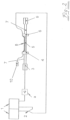
- the shielding attenuation can be determined using the parallel wire method according to VG 95214-6 with the Figure 2 shown structure.
- test specimen 5 was the inner conductor of a coaxial cable whose shielding had previously been removed and replaced with the protective tube according to the invention.
- Test specimen 5 was connected to two measurement fixtures 4 and 6, which in the specific test setup were formed by two brass plates with soldered N-type sockets.
- the inner conductor of the coaxial cable ran through the N-type sockets, while the protective tube was electrically connected to the N-type sockets using screw clamps.
- the interference power was fed to the parallel wire 8 from a network analyzer 1 (RF generator from Rohde & Schwarz, type SMA100C, ID No. 2.81.01, calibrated 06/2012; and test receiver from Rohde & Schwarz, type ESU8, ID No. 2.70.05, calibrated 09/2011) via a power divider 2 and the test fixture 6.
- the parallel wire 8 was connected to the test fixture 4 with a terminating impedance 10 (from Spinner, type 50 ⁇ /25W, ID No. 5.10.01, calibrated 10/2012).
- the test object 5 was connected to the test fixture 6 via a shielding tube 7 with a shielding housing 9, which was connected to a terminating impedance (from Rosenberger, type 50 ⁇ /0.25W, identification no.
- a power amplifier a can also be provided between the shielding housing 3 and the network analyzer.
- the measurements were performed on a wooden table in a shielded test booth. Shielding attenuation was measured in the frequency range from 10 kHz to 30 MHz.
- the measurement was carried out in the unstretched basic state of the protective tube according to the invention, in which it had a diameter of 20 mm.
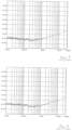
- the corresponding measurement result is shown in Figure 3
- the measurement was carried out in the expanded state of the protective tube according to the invention, in which it had a diameter of 45 mm.
- the corresponding measurement result is shown in Figure 4
- the two measurement results are practically identical, which means that the shielding effect of the protective tube according to the invention in its unstretched basic state and its shielding effect in the stretched state are essentially identical.
- FIG. 5 A knitted fabric 30 is shown that is suitable for producing a second embodiment of a protective tube according to the invention.
- the stitches 32 of the knitted fabric 30 are elongated in the longitudinal direction L of the protective tube, with the stitch sections 32a extending in the longitudinal direction L of the protective tube extending substantially parallel to one another and being considerably longer than the stitch sections 32b extending in the circumferential direction U of the protective tube.
Landscapes
- Engineering & Computer Science (AREA)
- Textile Engineering (AREA)
- Microelectronics & Electronic Packaging (AREA)
- Manufacturing & Machinery (AREA)
- Architecture (AREA)
- Civil Engineering (AREA)
- Structural Engineering (AREA)
- Shielding Devices Or Components To Electric Or Magnetic Fields (AREA)
- Insulated Conductors (AREA)
Description
- Die Erfindung betrifft einen in seinem Durchmesser elastisch aufweitbaren Schutzschlauch nach dem Oberbegriff des Anspruchs 1.
- Derartige Schutzschläuche werden beispielsweise verwendet, um elektrische Leitungen vor dem Einfluss von elektromagnetischen Störquellen zu schützen. Ein Anwendungsgebiet ist beispielsweise die Kraftfahrzeugtechnik, insbesondere die Verkabelung von Kraftfahrzeugen. Dabei tritt häufig die Situation auf, dass der Schutzschlauch über einen Stecker gezogen werden muss, der nicht lösbar mit der elektrischen Leitung bzw. dem elektrischen Kabel verbunden ist. Wichtig ist in diesem Zusammenhang die Rückstellfähigkeit des Schutzschlauchs, d.h. dessen Vermögen, sich nach Passieren des Steckers wieder auf einen an den Durchmesser der Leitung bzw. des Kabels angepassten Durchmesser zusammenziehen zu können.
- Ein Schutzschlauch ist beispielsweise aus der
EP 1 348 247 B1 bekannt. Der bekannte Schutzschlauch ist als Geflechtschlauch ausgebildet, wobei neben den Fäden aus elektrisch leitfähigem Material auch Kunststofffäden verarbeitet wurden, welche nach dem Aufweiten des Schutzschlauchs für die elastische Rückstellung des Schutzschlauchs sorgen. In der Praxis hat sich jedoch gezeigt, dass der bekannte Schutzschlauch in Längenabschnitten, in denen er im verbauten Zustand aufgeweitet bleibt, beispielsweise in einem einem Stecker unmittelbar benachbarten Längenabschnitt, ein geringeres Abschirmungsvermögen gegenüber elektromagnetischen Störeffekten aufweist als in Längenabschnitten, in denen er sich wieder vollständig zusammenziehen konnte. - Ferner ist aus dem Dokument
WO-A-03013208 - Des Weiteren ist aus dem Dokument
JP-H-1064353 A - Aus der
US-A-4375009 ist ein Schutzschlauch mit elektromagnetischer Abschirmung bekannt, in welchen zu isolierende Kabel eingeführt werden können, oder welcher um zu isolierende Kabel herum gestrickt oder/und geflochten werden kann. - Darüber hinaus seien die Dokumente
JP-A-2004190194 WO-A-0142702 US-A-2012148772 ,EP-A-2112731 ,JP-H-1070808 A EP 1 348 247 B1 ,WO 2008/043 948 A2 ,US 4 376 229 A ,US 2011/083 879 A1 ,EP 2 128 212 A2 ,DE 41 16 591 A1 undUS 4 452 279 A erwähnt. - Es ist daher Aufgabe der vorliegenden Erfindung, den gattungsgemäßen Schutzschlauch derart weiterzubilden, dass er im aufgeweiteten Zustand ein verbessertes Abschirmungsvermögen gegenüber elektromagnetischen Störeffekten, insbesondere elektromagnetischer Störstrahlung, zumindest in einem Frequenzbereich von 10 kHz bis 30 MHz, aufweist.
- Diese Aufgabe wird erfindungsgemäß durch einen Schutzschlauch gemäß Anspruch 1 gelöst. Die Ummantelung aus dem elastisch dehnbaren Material sorgt dabei dafür, dass die Fäden, aus denen der Schutzschlauch hergestellt ist, an den Stellen, an denen sie sich gegenseitig berühren, beim Aufweiten zuverlässig miteinander in Kontakt gehalten bleiben, so dass die durch die elektromagnetischen Störeffekte induzierten Wirbelströme unabhängig vom Aufweitungszustand des Schutzschlauchs im Wesentlichen ungehindert zirkulieren und somit ihre Abschirmungswirkung im Wesentlichen ungehindert entfalten können. Insbesondere zeigt eine EMV-Prüfung (EMV - elektromagnetische Verträglichkeit), dass die Abschirmung gegenüber elektromagnetischer Strahlung einer Frequenz von 10 kHz bis 30 MHz sowohl im nicht aufgeweiteten als auch im aufgeweiteten Zustand des Schutzschlauchs annähernd identisch ist.
- Als elastisch dehnbares Material kann beispielsweise Silikon verwendet werden. Grundsätzlich kann aber auch an den Einsatz von Polyurethan, Materialien auf Polyurethanbasis, Naturkautschuk oder allgemein Elastomere gedacht werden. Als Silikon kann beispielsweise das unter der Handelsbezeichnung Elastosil ® LR 3003/20 von der Wacker Chemie AG erhältliche Silikon verwendet werden.
- An dieser Stelle sei darauf hingewiesen, dass das Vorsehen einer Ummantelung aus einem elastisch dehnbaren Material bei Schutzschläuchen mit ausschließlich mechanischer oder/und thermischer Schutzfunktion an sich bekannt ist. Da diese Schutzschläuche ausschließlich aus Fäden ohne jegliche elektrische Leitfähigkeit hergestellt sind, legen diese Schutzschläuche dem Fachmann aber nicht nahe, dass durch eine derartige Ummantelung auch die Abschirmungseigenschaften gegenüber elektromagnetischen Störeffekten verbessert werden könnten.
- Erfindungsgemäß ist der Schutzschlauch ein geflochtener Schutzschlauch. Beispielhaft wird ferner ein gestrickter (nicht-erfindungsgemäßer) Schutzschlauch für eine derartige Verwendung beschrieben werden.
- Im Falle eines Geflechts kann die Aufweitbarkeit durch den so genannten Schereneffekt der geflochtenen Fäden erzielt werden. Dabei ist gemäß dem ersten erfinderischen Aspekt ein flacher Flechtwinkel, d.h. ein relativ zur Längserstreckungsrichtung des Schutzschlauchs gemessener Flechtwinkel von weniger als 45°, vorzugsweise weniger als als 30°, vorgesehen.
- Hingegen kann im Falle eines Gestricks die Aufweitbarkeit dadurch bereitgestellt werden, dass man das Gestrick beim Ummanteln mit dem elastisch dehnbaren Material in Längserstreckungsrichtung des Schutzschlauchs unter Zugspannung gesetzt hält, so dass die Maschen des Gestricks gestreckt sind. Auf diese Weise kann die gestreckte Gestalt der Maschen durch die elastisch dehnbare Ummantelung quasi "eingefroren" werden. Gemäß dem zweiten erfinderischen Aspekt verlaufen die in Längsrichtung des Schutzschlauchs verlaufenden Maschenabschnitte zueinander im Wesentlichen parallel. Aufgrund der elastischen Dehnbarkeit der Ummantelung kann der Schlauch aber aufgeweitet werden, ohne dass sich die Maschen relativ zueinander verschieben, weil die Ummantelung die einander an den Maschenpunkten berührenden Fadenabschnitte dort fixiert.
- Im Hinblick auf die Dehnbarkeit des gestrickten Schutzschlauchs ist es erfindungsgemäß vorgesehen, dass im nicht aufgeweiteten Zustand des Schutzschlauchs das Verhältnis der Länge der in Längsrichtung des Schutzschlauchs verlaufenden Maschenabschnitten zur Länge der in Umfangsrichtung des Schutzschlauchs verlaufenden Maschenabschnitte wenigstens 2 beträgt. Vorzugsweise kann dieses Verhältnis wenigstens 3, noch bevorzugter wenigstens 5 betragen.
- Gemäß der Erfindung ist vorgesehen, dass wenigstens einer der Fäden, vorzugsweise alle Fäden, eine Mehrzahl von Fasern umfasst, von denen wenigstens einige, vorzugsweise alle, aus elektrisch leitfähigem Material hergestellt sind. Das Vorsehen einer Mehrzahl von Fasern aus elektrisch leitfähigem Material pro Faden hat den Vorteil, dass sich die Fasern zweier aneinander anliegender Fäden derart anordnen, dass beide Fäden eine abgeflachte Querschnittsfläche aufweisen. Hierdurch erhöht sich die Anzahl der einander berührenden Fasern, was sich wiederum auf das Zirkulieren der durch die elektromagnetischen Störeffekte induzierten Wirbelströme und somit auf die Abschirmwirkung positiv auswirkt. Vorzugsweise werden die Fasern infolge der Abflachung nebeneinander angeordnet. Sind alle Fasern aller Fäden aus elektrisch leitfähigem Material ausgebildet, so ergibt sich zudem die bestmögliche Abschirmwirkung. Die Ummantelung aus dem elastisch dehnbaren Material sorgt bei der Aufdehnung des Schutzschlauchs dafür, dass sich die Fasern der Fäden nicht zusammenhäufen können, sondern dass die Nebeneinanderanordnung der Fasern der Fäden und somit die Güte der Abschirmwirkung aufrechterhalten bleibt. Zusätzlich oder alternativ zu Fasern mit kreisscheibenförmiger Querschnittsfläche können zur Verbesserung der Abschirmwirkung auch Fasern mit abgeflachtem Querschnitt verwendet werden.
- An dieser Stelle sei angemerkt, dass eine aus einem elektrisch leitfähigen Material hergestellte Faser auch als ''Draht" bezeichnet werden kann. Im Zusammenhang mit der vorliegenden Erfindung wird aber gleichwohl der Begriff "Faser" verwendet werden.
- Zur Verbesserung der Abschirmwirkung ist es ferner vorteilhaft, wenn wenigstens ein Faden, vorzugsweise jeder Faden, oder/und wenigstens eine Faser, vorzugsweise jede Faser, aus Kupfer, vorzugsweise verzinntem oder versilbertem Kupfer, hergestellt ist bzw. sind. Kupfer ist dabei wegen seiner hohen Leitfähigkeit vorteilhaft. Und durch das Verzinnen kann die Korrosionsbeständigkeit oder/und die Lötbarkeit des Schutzschlauchs den. Im Hinblick auf eine hohe Leitfähigkeit können die Kupferfasern aber auch versilbert sein.
- Um die Aufweitbarkeit des Schutzschlauchs verbessern zu können, ist es gemäß der Erfindung so, dass die Reißdehnbarkeit des elastisch dehnbaren Materials mehr als 200%, vorzugsweise mehr als 500%, noch bevorzugter mindestens 800%, beträgt. Die "Reißdehnbarkeit" wird dabei dadurch bestimmt, dass man einen Materialstreifen vorbestimmter Länge solange dehnt, bis er reißt. Die Länge, die der Materialstreifen aufweist unmittelbar bevor er reißt, geteilt durch die vorbestimmte Länge ergibt einen dimensionslosen, als "Reißdehnbarkeit" bezeichneten Wert. Der Wert der Reißdehnbarkeit des elastisch dehnbaren Materials kann in Abhängigkeit von der Dehnbarkeit des Schutzschlauchs, insbesondere des Geflechts oder des Gestricks, gewählt werden.
- Ist die Ummantelung, wie erfindungsgemäß vorgeschlagen, durchbrechungsfrei ausgebildet, so verfügt der Schutzschlauch zum einen bei Aufweitung über sehr gute Rückstelleigenschaften, da sich die Ummantelung nach Aufweitung vollflächig wieder zusammenzieht. Zum anderen kann die durchbrechungsfreie Ummantelung aber auch einen Schutz vor Feuchtigkeit bereitstellen. Darüber hinaus stellt eine durchbrechungsfreie Ummantelung eine gleichmäßige Aufdehnung des Schutzschlauchs sicher. Schließlich ermöglicht sie eine durchgehende Einfärbung des Schutzschlauchs. Eine derartige durchgehende Einfärbung, insbesondere in Signalorange, ist beispielsweise in Elektro- und Hybridfahrzeugen für die den Antriebsstrom führenden Kabel erforderlich.
- Erfindungsgemäß haftet die Ummantelung den Fäden zumindest an deren der Außenumfangsfläche des Schlauches zugewandter Seite an. Ein vollständiges Einbetten der Fäden bzw. Fasern in das elastisch dehnbare Material ist nicht erforderlich. Vielmehr genügt es, die Fäden bzw. Fasern so miteinander zu verkleben, dass sie beim Aufweiten des Schutzschlauchs miteinander in Kontakt gehalten bleiben. Dies kann auch nur von der Außenseite der Fäden bzw. Fasern her erfolgen.
- Die Erfindung wird im Folgenden anhand der beigefügten Zeichnung an einem Ausführungsbeispiel näher erläutert werden. Es stellt dar:
- Figur 1
- eine teilweise geschnittene Darstellung eines erfindungsgemäßen Schutzschlauchs;
- Figur 2
- eine schematische Darstellung eines Messaufbaus zur Bestimmung der Schirmdämpfung des in
Figur 1 dargestellten Schutzschlauchs; - Figuren 3 und 4
- die Messergebnisse der Schirmdämpfungsmessung an dem in
Figur 1 dargestellten Schutzschlauch unter Verwendung des inFigur 2 dargestellten Messaufbaus, und zwar im ungedehnten Zustand (Figur 3 ) und im gedehnten Zustand (Figur 4 ); und - Figur 5
- eine grobschematische Darstellung eines Gestricks, das zur Herstellung einer weiteren Ausführungsform eines erfindungsgemäßen Schutzschlauchs verwendet werden kann.
- In
Figur 1 ist ein als Geflechtschlauch ausgebildeter Schutzschlauch allgemein mit 20 bezeichnet. Der Geflechtschlauch 20 ist aus einer Mehrzahl von einander kreuzenden Fäden 22 und 24 gebildet. Dabei beträgt der relativ zur Längserstreckungsrichtung L des Schutzschlauchs 20 gemessene Flechtwinkel α der Fäden 22, 24 höchstens 45°. Wie inFigur 1 bei 26 angedeutet, umfasst jeder der Fäden 22, 24 sechzehn Fasern bzw. Drähte aus verzinntem Kupfer mit einem Durchmesser von jeweils 0,10 mm. Im nicht aufgeweiteten Zustand des Schutzschlauchs 20 beträgt dessen Durchmesser etwa 20 mm. Auf den Schutzschlauch 20 wird eine zwischen etwa 0,5 mm und etwa 1,0 mm dicke Schicht 28 aus dem unter der Handelsbezeichnung Elastosil ® LR 3003/20 von der Wacker Chemie AG erhältlichen Silikon aufgetragen. Der so hergestellte Schutzschlauch 20 ist in einem Temperaturbereich von -40°C bis +150°C für mindestens 3000 Stunden und in einem Temperaturbereich von -40°C bis +175°C für mindestens 1500 Stunden temperaturbeständig. - Das Abschirmvermögen dieses Schutzschlauchs 20 kann durch das Maß der so genannten Schirmdämpfung beschrieben werden. Diese Schirmdämpfung ist das Verhältnis einer Störleistung im Raum zur maximal hervorgerufenen Leistung innerhalb der/des vom Schutzschlauch umgebenen Leitung/Kabels. Genauer gesagt ist die Schirmdämpfung das Verhältnis des Werts der elektrische Feldstärke außerhalb des Schlauchs zum Wert der elektrischen Feldstärke innerhalb des Schlauchs. Sie wird in der Einheit "dB" angegeben. Die Schirmdämpfung kann nach dem so genannten Paralleldraht-Verfahren nach der VG 95214-6 mit dem in
Figur 2 dargestellten Aufbau bestimmt werden. - Als Prüfling 5 wurde im vorliegenden Fall der Innenleiter eines Koaxialkabels verwendet, dessen Abschirmung zuvor entfernt und durch das erfindungsgemäße Schutzrohr ersetzt worden war. Der Prüfling 5 wurde an zwei Messaufnahmen 4 und 6 angeschlossen, die im konkreten Versuchsaufbau von zwei Messingplatten mit aufgelöteten N-Buchsen gebildet waren. Der Innenleiter des Koaxialkabels verlief durch die N-Buchsen hindurch, während das Schutzrohr mittels Schraubschellen mit den N-Buchsen elektrisch leitend verbunden wurde. Zwischen den Messaufnahmen 4 und 6 verlief ferner ein als Störquelle dienender Paralleldraht 8.
- Die Störleistung wurde dem Paralleldraht 8 von einem Netzwerkanalysator 1 (HF-Generator der Fa. Rohde & Schwarz, Typ SMA100C, Kenn-Nr. 2.81.01, kalibriert 06/2012; und Messempfänger der Fa. Rohde & Schwarz, Typ ESU8, Kenn-Nr. 2.70.05, kalibriert 09/2011) über einen Leistungsteiler 2 und die Messaufnahme 6 zugeführt. Zudem war der Paralleldraht 8 an der Messaufnahme 4 mit einer Abschlussimpedanz 10 (Fa. Spinner, Typ 50Ω/25W, Kenn-Nr. 5.10.01, kalibriert 10/2012) verbunden. Der Prüfling 5 war an der Messaufnahme 6 über ein Schirmrohr 7 mit einem schirmenden Gehäuse 9 verbunden, das mit einer Abschlussimpedanz (Fa. Rosenberger, Typ 50Ω/0,25W, Kenn-Nr. 5.10.16, kalibriert 10/2012) versehen war, und an der Messaufnahme 4 über ein weiteres Schirmrohr 7 mit einem schirmenden Gehäuse 3, über das das im Prüfling 5 induzierte Signal dem Netzwerkanalysator 1 zugeführt wurde. Zwischen dem schirmenden Gehäuse 3 und dem Netzwerkanalysator kann erforderlichenfalls ferner ein Leistungsverstärker a vorgesehen werden.
- Die Messungen erfolgten auf einem Holztisch in einer geschirmten Messkabine. Die Schirmdämpfung wurde im Frequenzbereich von 10 kHz bis 30 MHz durchgeführt.
- Zum einen wurde die Messung im ungedehnten Grundzustand des erfindungsgemäßen Schutzrohrs durchgeführt, in dem er einen Durchmesser von 20 mm aufwies. Das entsprechende Messergebnis ist in
Figur 3 dargestellt. Und zum anderen wurde die Messung im aufgeweiteten Zustand des erfindungsgemäßen Schutzrohrs durchgeführt, in dem er einen Durchmesser von 45 mm aufwies. Das entsprechende Messergebnis ist inFigur 4 dargestellt. Wie man leicht erkennt, unterscheiden sich die beiden Messergebnisse praktisch nicht, was bedeutet, dass die Abschirmwirkung des erfindungsgemäßen Schutzschlauchs im ungedehnten Grundzustand und dessen Abschirmwirkung im gedehnten Zustand im Wesentlichen identisch sind. - In
Figur 5 ist ein Gestrick 30 dargestellt, das sich zur Herstellung einer zweiten Ausführungsform eines erfindungsgemäßen Schutzschlauchs eignet. Insbesondere sind die Maschen 32 des Gestricks 30 in Längsrichtung L des Schutzschlauchs länglich ausgebildet, wobei die in Längsrichtung L des Schutzschlauchs verlaufenden Maschenabschnitte 32a zueinander im Wesentlichen parallel verlaufen und erheblich länger bemessen sind als die in Umfangsrichtung U des Schutzschlauchs verlaufenden Maschenabschnitte 32b.
Claims (3)
- In seinem Durchmesser elastisch aufweitbarer Schutzschlauch (20) mit elektromagnetischer Abschirmung, der unter Verwendung von Fäden (22, 24) hergestellt ist, welche zumindest teilweise aus elektrisch leitfähigem Material hergestellt sind,wobei der Schutzschlauch (20) geflochten ist,dadurch gekennzeichnet, dass er mit einer Schicht (28) aus einem elastisch dehnbaren Material ummantelt ist, und wobei die Ummantelung (28) aus dem elastisch dehnbaren Material den Fäden (22, 24) zumindest an deren der Außenumfangsfläche des Schlauches (20) zugewandter Seite anhaftet, und zwar derart, dass die Fäden an den Stellen, an denen sie sich gegenseitig berühren, derart miteinander verklebt sind, dass sie beim Aufweiten zuverlässig miteinander in Kontakt gehalten bleiben,dass die Ummantelung (28) aus dem elastisch dehnbaren Material durchbrechungsfrei ausgebildet ist,dass der Flechtwinkel (α) weniger als 45° beträgt,dass die Reißdehnbarkeit des elastisch dehnbaren Materials mehr als 200% beträgt, unddass wenigstens einer der Fäden (22, 24) eine Mehrzahl von Fasern umfasst, von denen wenigstens einige aus elektrisch leitfähigem Material hergestellt sind, wobei die Fasern dazu eingerichtet sind, dass sich die Fasern zweier aneinander anliegender Fäden derart anordnen, dass beide Fäden eine abgeflachte Querschnittsfläche aufweisen, so dass sich die Anzahl der einander berührenden Fasern erhöht, was sich wiederum auf das Zirkulieren der durch die elektromagnetischen Störeffekte induzierten Wirbelströme und somit auf die Abschirmwirkung positiv auswirkt.
- Schutzschlauch nach Anspruch 1,
dadurch gekennzeichnet, dass wenigstens ein Faden oder/und wenigstens eine Faser aus Kupfer oder verzinntem Kupfer hergestellt sind. - Schutzschlauch nach Anspruch 1 oder 2,
dadurch gekennzeichnet, dass wenigstens ein Faden oder/und wenigstens eine Faser aus Aluminium hergestellt sind.
Applications Claiming Priority (1)
| Application Number | Priority Date | Filing Date | Title |
|---|---|---|---|
| DE201310208250 DE102013208250A1 (de) | 2013-05-06 | 2013-05-06 | Schutzschlauch mit elektromagnetischer Abschirmung |
Publications (2)
| Publication Number | Publication Date |
|---|---|
| EP2802048A1 EP2802048A1 (de) | 2014-11-12 |
| EP2802048B1 true EP2802048B1 (de) | 2025-06-04 |
Family
ID=50679883
Family Applications (1)
| Application Number | Title | Priority Date | Filing Date |
|---|---|---|---|
| EP14166972.1A Active EP2802048B1 (de) | 2013-05-06 | 2014-05-05 | Schutzschlauch mit elektromagnetischer Abschirmung |
Country Status (2)
| Country | Link |
|---|---|
| EP (1) | EP2802048B1 (de) |
| DE (1) | DE102013208250A1 (de) |
Families Citing this family (2)
| Publication number | Priority date | Publication date | Assignee | Title |
|---|---|---|---|---|
| DE102015003061A1 (de) * | 2015-03-10 | 2016-09-15 | Sumitomo Wiring Systems, Ltd. | Abgeschirmte Verkabelung, abschirmendes Glied und Verfahren zum Herstellen einer abgeschirmten Verkabelung |
| EP3529870B1 (de) * | 2016-10-18 | 2023-07-12 | Safran Aerosystems | Schutzhülle insbesondere zur aufnahme von elektrischen kabeln |
Citations (7)
| Publication number | Priority date | Publication date | Assignee | Title |
|---|---|---|---|---|
| US4375009A (en) * | 1980-12-10 | 1983-02-22 | Hewlett-Packard Company | Shielded electrical cable |
| US4376229A (en) * | 1980-09-16 | 1983-03-08 | Raychem Corporation | Shielded conduit |
| US4452279A (en) * | 1982-02-16 | 1984-06-05 | Titeflex Corporation | Silicone/elastomer fiberglass sleeves |
| DE4116591A1 (de) * | 1991-02-14 | 1992-08-20 | Eilentropp Kg | Flexibler schutzschlauch fuer langgestrecktes gut |
| WO2008043948A2 (fr) * | 2006-10-11 | 2008-04-17 | Nexans | Cable de contrôle éléctrique et procédé de fabrication associé |
| EP2128212A2 (de) * | 2008-05-23 | 2009-12-02 | tesa SE | Klebeband mit textilem Träger für die Kabelbandagierung |
| US20110083879A1 (en) * | 2009-10-07 | 2011-04-14 | Avula Ramesh R | Flexible textile sleeve with end fray resistant, protective coating and method of construction thereof |
Family Cites Families (11)
| Publication number | Priority date | Publication date | Assignee | Title |
|---|---|---|---|---|
| US4684762A (en) * | 1985-05-17 | 1987-08-04 | Raychem Corp. | Shielding fabric |
| US5387113A (en) * | 1992-09-24 | 1995-02-07 | Woven Electronics Corp. | Composite shield jacket for electrical transmission cable |
| JPH1070808A (ja) * | 1996-08-27 | 1998-03-10 | Tokin Corp | スパイラルチューブ |
| JP3729571B2 (ja) * | 1996-08-26 | 2005-12-21 | Necトーキン株式会社 | デジタル電子機器用チューブ付ケーブル |
| GB2357133A (en) * | 1999-12-10 | 2001-06-13 | Federal Mogul Technology Ltd | Flexible protective sleeve |
| FR2812465A1 (fr) * | 2000-07-26 | 2002-02-01 | Rubans Gallant | Gaine souple de protection |
| FR2819092B1 (fr) | 2001-01-03 | 2003-02-28 | Tresse Ind | Gaine de blindage electromagnetique, a diametre extensible |
| JP2003060386A (ja) * | 2001-07-27 | 2003-02-28 | Three M Innovative Properties Co | 電磁波シールド用被覆体 |
| JP2004190194A (ja) * | 2002-12-13 | 2004-07-08 | Yoshio Imai | 電磁波遮蔽編織用複合糸および電磁波遮蔽編織物 |
| DE102008020220A1 (de) * | 2008-04-22 | 2009-10-29 | Damm, Hans | Vorrichtung zur Aufnahme einzelner elektrischer Leitungen |
| WO2012078833A1 (en) * | 2010-12-08 | 2012-06-14 | Federal-Mogul Powertrain, Inc. | Textile sleeve with protective coating and method of construction thereof |
-
2013
- 2013-05-06 DE DE201310208250 patent/DE102013208250A1/de not_active Withdrawn
-
2014
- 2014-05-05 EP EP14166972.1A patent/EP2802048B1/de active Active
Patent Citations (7)
| Publication number | Priority date | Publication date | Assignee | Title |
|---|---|---|---|---|
| US4376229A (en) * | 1980-09-16 | 1983-03-08 | Raychem Corporation | Shielded conduit |
| US4375009A (en) * | 1980-12-10 | 1983-02-22 | Hewlett-Packard Company | Shielded electrical cable |
| US4452279A (en) * | 1982-02-16 | 1984-06-05 | Titeflex Corporation | Silicone/elastomer fiberglass sleeves |
| DE4116591A1 (de) * | 1991-02-14 | 1992-08-20 | Eilentropp Kg | Flexibler schutzschlauch fuer langgestrecktes gut |
| WO2008043948A2 (fr) * | 2006-10-11 | 2008-04-17 | Nexans | Cable de contrôle éléctrique et procédé de fabrication associé |
| EP2128212A2 (de) * | 2008-05-23 | 2009-12-02 | tesa SE | Klebeband mit textilem Träger für die Kabelbandagierung |
| US20110083879A1 (en) * | 2009-10-07 | 2011-04-14 | Avula Ramesh R | Flexible textile sleeve with end fray resistant, protective coating and method of construction thereof |
Also Published As
| Publication number | Publication date |
|---|---|
| EP2802048A1 (de) | 2014-11-12 |
| DE102013208250A1 (de) | 2014-11-06 |
Similar Documents
| Publication | Publication Date | Title |
|---|---|---|
| DE69301156T2 (de) | Mehrzweigige abgeschirmte Verbindung | |
| DE69906052T2 (de) | Abgeschirmtes kabel und sein herstellungsverfahren | |
| DE602004006505T2 (de) | Elektromagnetischer abschirmmantel, der zum beispiel kabelbündel für die luftfahrt schützen soll | |
| DE102014214726B3 (de) | Datenkabel für High-Speed Datenübertragungen | |
| DE69323918T2 (de) | Elektrisches Kabel | |
| DE3428087A1 (de) | Konzentrisches dreileiterkabel | |
| DE102018213095B4 (de) | Kabelbaum mit Elektrodrähte umgebendem Abschirmelement | |
| DE112012000867B4 (de) | Abgeschirmtes Kabel | |
| EP1225598B1 (de) | Flexible elektrische Leitung | |
| WO2007045345A1 (de) | Dreileiterkabel | |
| DE112018000803T5 (de) | Schutzelement, Fahrzeug-Hochvoltleitung und Kabelstrang | |
| DE19907675A1 (de) | Kabelschirm aus Faserverbundwerkstoffen mit hohem Anteil an elektrisch leitfähigen Fasern zur elektromagnetischen Abschirmung | |
| CH695967A5 (de) | Elektrokabel. | |
| DE69510312T2 (de) | Herstellungsverfahren eines Abschirmungsmantels auf einem elektrischen Leiterbündel, und so erhaltener Bündel | |
| AT515598B1 (de) | Elektrische Leitung zum Übertragen von Datensignalen | |
| EP2802048A1 (de) | Schutzschlauch mit elektromagnetischer Abschirmung | |
| WO2017076984A1 (de) | Datenkabel sowie verwendung des datenkabels in einem kraftfahrzeug | |
| DE102016215252A1 (de) | Kabel mit angepasster Verseilung | |
| DE848664C (de) | Elektrisches Kabel mit einer oder mehreren mit leitenden Stoffen in feiner Verteilung durchsetzten Isolierschichten | |
| DE102016221412B4 (de) | Quetschverbindung für geflechtartiges Abschirmmaterial zur Verwendung in mit kapazitiven Sensoren ausgestatteten Lenkrädern | |
| DE691077C (de) | Verfahren zur Herstellung einer luftraumisolierten elektrischen Leitung | |
| EP3586578B1 (de) | Schlauchkombination mit elektromagnetischer abschirmung, schlauch mit elektromagnetischer abschirmung und verwendung einer derartigen schlauchkombination bzw. eines derartigen schlauchs | |
| DE2948031C2 (de) | Temperaturstabile Schaltleitung für elektrische Wärmegeräte | |
| DE20309934U1 (de) | Schutzvorrichtung für Kabel u.dgl. | |
| DE102017204266A1 (de) | Leitung |
Legal Events
| Date | Code | Title | Description |
|---|---|---|---|
| PUAI | Public reference made under article 153(3) epc to a published international application that has entered the european phase |
Free format text: ORIGINAL CODE: 0009012 |
|
| 17P | Request for examination filed |
Effective date: 20140505 |
|
| AK | Designated contracting states |
Kind code of ref document: A1 Designated state(s): AL AT BE BG CH CY CZ DE DK EE ES FI FR GB GR HR HU IE IS IT LI LT LU LV MC MK MT NL NO PL PT RO RS SE SI SK SM TR |
|
| AX | Request for extension of the european patent |
Extension state: BA ME |
|
| R17P | Request for examination filed (corrected) |
Effective date: 20150511 |
|
| RBV | Designated contracting states (corrected) |
Designated state(s): AL AT BE BG CH CY CZ DE DK EE ES FI FR GB GR HR HU IE IS IT LI LT LU LV MC MK MT NL NO PL PT RO RS SE SI SK SM TR |
|
| 17Q | First examination report despatched |
Effective date: 20160321 |
|
| STAA | Information on the status of an ep patent application or granted ep patent |
Free format text: STATUS: EXAMINATION IS IN PROGRESS |
|
| GRAP | Despatch of communication of intention to grant a patent |
Free format text: ORIGINAL CODE: EPIDOSNIGR1 |
|
| STAA | Information on the status of an ep patent application or granted ep patent |
Free format text: STATUS: GRANT OF PATENT IS INTENDED |
|
| INTG | Intention to grant announced |
Effective date: 20241212 |
|
| GRAS | Grant fee paid |
Free format text: ORIGINAL CODE: EPIDOSNIGR3 |
|
| GRAA | (expected) grant |
Free format text: ORIGINAL CODE: 0009210 |
|
| STAA | Information on the status of an ep patent application or granted ep patent |
Free format text: STATUS: THE PATENT HAS BEEN GRANTED |
|
| P01 | Opt-out of the competence of the unified patent court (upc) registered |
Free format text: CASE NUMBER: APP_15599/2025 Effective date: 20250331 |
|
| AK | Designated contracting states |
Kind code of ref document: B1 Designated state(s): AL AT BE BG CH CY CZ DE DK EE ES FI FR GB GR HR HU IE IS IT LI LT LU LV MC MK MT NL NO PL PT RO RS SE SI SK SM TR |
|
| REG | Reference to a national code |
Ref country code: GB Ref legal event code: FG4D Free format text: NOT ENGLISH |
|
| REG | Reference to a national code |
Ref country code: CH Ref legal event code: EP |
|
| REG | Reference to a national code |
Ref country code: DE Ref legal event code: R096 Ref document number: 502014016934 Country of ref document: DE |
|
| REG | Reference to a national code |
Ref country code: IE Ref legal event code: FG4D Free format text: LANGUAGE OF EP DOCUMENT: GERMAN |
|
| REG | Reference to a national code |
Ref country code: NL Ref legal event code: MP Effective date: 20250604 |
|
| PG25 | Lapsed in a contracting state [announced via postgrant information from national office to epo] |
Ref country code: FI Free format text: LAPSE BECAUSE OF FAILURE TO SUBMIT A TRANSLATION OF THE DESCRIPTION OR TO PAY THE FEE WITHIN THE PRESCRIBED TIME-LIMIT Effective date: 20250604 Ref country code: ES Free format text: LAPSE BECAUSE OF FAILURE TO SUBMIT A TRANSLATION OF THE DESCRIPTION OR TO PAY THE FEE WITHIN THE PRESCRIBED TIME-LIMIT Effective date: 20250604 |
|
| REG | Reference to a national code |
Ref country code: LT Ref legal event code: MG9D |
|
| PG25 | Lapsed in a contracting state [announced via postgrant information from national office to epo] |
Ref country code: GR Free format text: LAPSE BECAUSE OF FAILURE TO SUBMIT A TRANSLATION OF THE DESCRIPTION OR TO PAY THE FEE WITHIN THE PRESCRIBED TIME-LIMIT Effective date: 20250905 Ref country code: NO Free format text: LAPSE BECAUSE OF FAILURE TO SUBMIT A TRANSLATION OF THE DESCRIPTION OR TO PAY THE FEE WITHIN THE PRESCRIBED TIME-LIMIT Effective date: 20250904 |
|
| PG25 | Lapsed in a contracting state [announced via postgrant information from national office to epo] |
Ref country code: PL Free format text: LAPSE BECAUSE OF FAILURE TO SUBMIT A TRANSLATION OF THE DESCRIPTION OR TO PAY THE FEE WITHIN THE PRESCRIBED TIME-LIMIT Effective date: 20250604 |
|
| PG25 | Lapsed in a contracting state [announced via postgrant information from national office to epo] |
Ref country code: BG Free format text: LAPSE BECAUSE OF FAILURE TO SUBMIT A TRANSLATION OF THE DESCRIPTION OR TO PAY THE FEE WITHIN THE PRESCRIBED TIME-LIMIT Effective date: 20250604 |
|
| PG25 | Lapsed in a contracting state [announced via postgrant information from national office to epo] |
Ref country code: HR Free format text: LAPSE BECAUSE OF FAILURE TO SUBMIT A TRANSLATION OF THE DESCRIPTION OR TO PAY THE FEE WITHIN THE PRESCRIBED TIME-LIMIT Effective date: 20250604 |
|
| PG25 | Lapsed in a contracting state [announced via postgrant information from national office to epo] |
Ref country code: RS Free format text: LAPSE BECAUSE OF FAILURE TO SUBMIT A TRANSLATION OF THE DESCRIPTION OR TO PAY THE FEE WITHIN THE PRESCRIBED TIME-LIMIT Effective date: 20250904 |
|
| PG25 | Lapsed in a contracting state [announced via postgrant information from national office to epo] |
Ref country code: LV Free format text: LAPSE BECAUSE OF FAILURE TO SUBMIT A TRANSLATION OF THE DESCRIPTION OR TO PAY THE FEE WITHIN THE PRESCRIBED TIME-LIMIT Effective date: 20250604 |
|
| PG25 | Lapsed in a contracting state [announced via postgrant information from national office to epo] |
Ref country code: NL Free format text: LAPSE BECAUSE OF FAILURE TO SUBMIT A TRANSLATION OF THE DESCRIPTION OR TO PAY THE FEE WITHIN THE PRESCRIBED TIME-LIMIT Effective date: 20250604 |
|
| PG25 | Lapsed in a contracting state [announced via postgrant information from national office to epo] |
Ref country code: PT Free format text: LAPSE BECAUSE OF FAILURE TO SUBMIT A TRANSLATION OF THE DESCRIPTION OR TO PAY THE FEE WITHIN THE PRESCRIBED TIME-LIMIT Effective date: 20251006 |
|
| PG25 | Lapsed in a contracting state [announced via postgrant information from national office to epo] |
Ref country code: IS Free format text: LAPSE BECAUSE OF FAILURE TO SUBMIT A TRANSLATION OF THE DESCRIPTION OR TO PAY THE FEE WITHIN THE PRESCRIBED TIME-LIMIT Effective date: 20251004 |
|
| PG25 | Lapsed in a contracting state [announced via postgrant information from national office to epo] |
Ref country code: SM Free format text: LAPSE BECAUSE OF FAILURE TO SUBMIT A TRANSLATION OF THE DESCRIPTION OR TO PAY THE FEE WITHIN THE PRESCRIBED TIME-LIMIT Effective date: 20250604 |
|
| PG25 | Lapsed in a contracting state [announced via postgrant information from national office to epo] |
Ref country code: CZ Free format text: LAPSE BECAUSE OF FAILURE TO SUBMIT A TRANSLATION OF THE DESCRIPTION OR TO PAY THE FEE WITHIN THE PRESCRIBED TIME-LIMIT Effective date: 20250604 |
|
| PG25 | Lapsed in a contracting state [announced via postgrant information from national office to epo] |
Ref country code: EE Free format text: LAPSE BECAUSE OF FAILURE TO SUBMIT A TRANSLATION OF THE DESCRIPTION OR TO PAY THE FEE WITHIN THE PRESCRIBED TIME-LIMIT Effective date: 20250604 |
|
| PG25 | Lapsed in a contracting state [announced via postgrant information from national office to epo] |
Ref country code: SK Free format text: LAPSE BECAUSE OF FAILURE TO SUBMIT A TRANSLATION OF THE DESCRIPTION OR TO PAY THE FEE WITHIN THE PRESCRIBED TIME-LIMIT Effective date: 20250604 Ref country code: RO Free format text: LAPSE BECAUSE OF FAILURE TO SUBMIT A TRANSLATION OF THE DESCRIPTION OR TO PAY THE FEE WITHIN THE PRESCRIBED TIME-LIMIT Effective date: 20250604 |
|
| PG25 | Lapsed in a contracting state [announced via postgrant information from national office to epo] |
Ref country code: IT Free format text: LAPSE BECAUSE OF FAILURE TO SUBMIT A TRANSLATION OF THE DESCRIPTION OR TO PAY THE FEE WITHIN THE PRESCRIBED TIME-LIMIT Effective date: 20250604 |
|
| REG | Reference to a national code |
Ref country code: DE Ref legal event code: R097 Ref document number: 502014016934 Country of ref document: DE |
|
| PLBE | No opposition filed within time limit |
Free format text: ORIGINAL CODE: 0009261 |
|
| STAA | Information on the status of an ep patent application or granted ep patent |
Free format text: STATUS: NO OPPOSITION FILED WITHIN TIME LIMIT |
|
| PG25 | Lapsed in a contracting state [announced via postgrant information from national office to epo] |
Ref country code: DK Free format text: LAPSE BECAUSE OF FAILURE TO SUBMIT A TRANSLATION OF THE DESCRIPTION OR TO PAY THE FEE WITHIN THE PRESCRIBED TIME-LIMIT Effective date: 20250604 |
|
| REG | Reference to a national code |
Ref country code: CH Ref legal event code: L10 Free format text: ST27 STATUS EVENT CODE: U-0-0-L10-L00 (AS PROVIDED BY THE NATIONAL OFFICE) Effective date: 20260416 |
|
| 26N | No opposition filed |
Effective date: 20260305 |