EP2801927B1 - System, Verfahren, und Vorrichtung zur Datenverarbeitung - Google Patents
System, Verfahren, und Vorrichtung zur Datenverarbeitung Download PDFInfo
- Publication number
- EP2801927B1 EP2801927B1 EP14167325.1A EP14167325A EP2801927B1 EP 2801927 B1 EP2801927 B1 EP 2801927B1 EP 14167325 A EP14167325 A EP 14167325A EP 2801927 B1 EP2801927 B1 EP 2801927B1
- Authority
- EP
- European Patent Office
- Prior art keywords
- user
- data
- unit
- Prior art date
- Legal status (The legal status is an assumption and is not a legal conclusion. Google has not performed a legal analysis and makes no representation as to the accuracy of the status listed.)
- Not-in-force
Links
Images










Classifications
-
- G—PHYSICS
- G06—COMPUTING OR CALCULATING; COUNTING
- G06F—ELECTRIC DIGITAL DATA PROCESSING
- G06F15/00—Digital computers in general; Data processing equipment in general
- G06F15/76—Architectures of general purpose stored program computers
-
- H—ELECTRICITY
- H04—ELECTRIC COMMUNICATION TECHNIQUE
- H04L—TRANSMISSION OF DIGITAL INFORMATION, e.g. TELEGRAPHIC COMMUNICATION
- H04L51/00—User-to-user messaging in packet-switching networks, transmitted according to store-and-forward or real-time protocols, e.g. e-mail
- H04L51/48—Message addressing, e.g. address format or anonymous messages, aliases
-
- G—PHYSICS
- G06—COMPUTING OR CALCULATING; COUNTING
- G06F—ELECTRIC DIGITAL DATA PROCESSING
- G06F15/00—Digital computers in general; Data processing equipment in general
-
- G—PHYSICS
- G06—COMPUTING OR CALCULATING; COUNTING
- G06F—ELECTRIC DIGITAL DATA PROCESSING
- G06F21/00—Security arrangements for protecting computers, components thereof, programs or data against unauthorised activity
- G06F21/60—Protecting data
- G06F21/606—Protecting data by securing the transmission between two devices or processes
- G06F21/608—Secure printing
-
- H—ELECTRICITY
- H04—ELECTRIC COMMUNICATION TECHNIQUE
- H04N—PICTORIAL COMMUNICATION, e.g. TELEVISION
- H04N1/00—Scanning, transmission or reproduction of documents or the like, e.g. facsimile transmission; Details thereof
- H04N1/44—Secrecy systems
- H04N1/4406—Restricting access, e.g. according to user identity
- H04N1/4413—Restricting access, e.g. according to user identity involving the use of passwords, ID codes or the like, e.g. PIN
-
- G—PHYSICS
- G06—COMPUTING OR CALCULATING; COUNTING
- G06F—ELECTRIC DIGITAL DATA PROCESSING
- G06F13/00—Interconnection of, or transfer of information or other signals between, memories, input/output devices or central processing units
-
- H—ELECTRICITY
- H04—ELECTRIC COMMUNICATION TECHNIQUE
- H04N—PICTORIAL COMMUNICATION, e.g. TELEVISION
- H04N2201/00—Indexing scheme relating to scanning, transmission or reproduction of documents or the like, and to details thereof
- H04N2201/0077—Types of the still picture apparatus
- H04N2201/0094—Multifunctional device, i.e. a device capable of all of reading, reproducing, copying, facsimile transception, file transception
-
- H—ELECTRICITY
- H04—ELECTRIC COMMUNICATION TECHNIQUE
- H04N—PICTORIAL COMMUNICATION, e.g. TELEVISION
- H04N2201/00—Indexing scheme relating to scanning, transmission or reproduction of documents or the like, and to details thereof
- H04N2201/32—Circuits or arrangements for control or supervision between transmitter and receiver or between image input and image output device, e.g. between a still-image camera and its memory or between a still-image camera and a printer device
- H04N2201/3201—Display, printing, storage or transmission of additional information, e.g. ID code, date and time or title
- H04N2201/3204—Display, printing, storage or transmission of additional information, e.g. ID code, date and time or title of data relating to a user, sender, addressee, machine or electronic recording medium
- H04N2201/3205—Display, printing, storage or transmission of additional information, e.g. ID code, date and time or title of data relating to a user, sender, addressee, machine or electronic recording medium of identification information, e.g. name or ID code
-
- H—ELECTRICITY
- H04—ELECTRIC COMMUNICATION TECHNIQUE
- H04N—PICTORIAL COMMUNICATION, e.g. TELEVISION
- H04N2201/00—Indexing scheme relating to scanning, transmission or reproduction of documents or the like, and to details thereof
- H04N2201/32—Circuits or arrangements for control or supervision between transmitter and receiver or between image input and image output device, e.g. between a still-image camera and its memory or between a still-image camera and a printer device
- H04N2201/3201—Display, printing, storage or transmission of additional information, e.g. ID code, date and time or title
- H04N2201/3274—Storage or retrieval of prestored additional information
- H04N2201/3276—Storage or retrieval of prestored additional information of a customised additional information profile, e.g. a profile specific to a user ID
Definitions
- the present invention relates to a system, a method, and an apparatus for data processing.
- US 2004/0001226 A1 pertains to a system according to the preamble of claim 1.
- the present invention may provide a system, a method, and an apparatus for data processing that substantially obviates one or more of the problems caused by the limitations and disadvantages of the related art.
- embodiments of the present invention provide in a data process system according to claim 1 and a data process method according to claim 5.
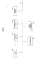
- Fig. 1 is a schematic diagram illustrating a configuration of a printing system 1 according to a first embodiment of the present invention.
- the printing system 1 illustrated in Fig. 1 includes, for example, one or more user terminals 30, a mail server 40, a management server 10, an authentication server 50, a storage server 60, and one or more image forming apparatuses 20 that are communicably connected to each other via a network N1 such as a LAN (Local Area Network) or the Internet.
- the network N1 may be partly or entirely constituted by a wireless communication network. Further, a mobile communication network may be provided between the user terminal 30 and the network N1.
- the printing system 1 is operated inside an organization such as a company. In the first embodiment, the organization is referred to as "company A".
- the user terminal 30 is a data processing apparatus on which the user of the printing system 1 directly operates for inputting printing requests to the printing system 1.
- a PC Personal Computer
- a mobile phone a smartphone
- a table type terminal a PDA (Personal Digital Assistance)
- PDA Personal Digital Assistance
- each of the user terminals 30 may be different kinds of terminals.
- the users of the printing system 1 are categorized into a "regular user (qualified user)" and a "guest user".
- the "regular user” is a user whose information (data) is registered in the printing system 1 (technically, registered in the below-described user data storage unit 52). That is, the "regular user” is a user expected to be a user of the printing system 1.
- One example of the regular user is an employee of company A.
- the "guest user” is a user whose information is not registered in the printing system 1. That is, the guest user is a user that does not initially have the authority to use the printing system 1.
- One example of the guest user is a person other than an employee of company A.
- the mail server 40 is a computer that transfers, for example, electronic mail transmitted from the user terminal 30 or from the management server 10.
- the user terminal 30 transmits electronic mail including a print request to the management server 10 in response to an instruction from the user.
- Electronic data that is to be printed (target print data) is attached to the electronic mail including the print request.
- the data format of the electronic data is not limited to a particular format.
- the electronic mail that includes the print request and is transmitted from the user terminal 30 may also be hereinafter referred to as "print request mail".
- the authentication server 50 is a computer that manages data of each user of company A (user data) and performs various processes using the user data, For example, the authentication server 50 performs an authentication process in response to an authentication request including, for example, a designated user name and a designated password. Further, the authentication server 50 performs various processes corresponding to requests such as a request to confirm existence of an e-mail address or a request to obtain a user name corresponding to an e-mail address. That is, the user data is associated to a user name and includes an e-mail address of the user.
- the management server 10 is a computer that performs processes such as generation of print data pertaining to the electronic data included in the print request mail upon receiving the print request mail.
- the data format of the print data is a format that can be interpreted by the image forming apparatus 20.
- the management server 10 associates the generated print data with respect to a user name of a user of a transmission source (sender) from which the print request mail is transmitted, or with respect to an identifier generated in correspondence with each print request mail. Then, the management server 10 transmits the associated print data to the storage server 60.
- the authentication server 50 manages addresses of transmission sources of print request mail in correspondence with user names
- print data are associated with user names.
- print data are associated with identifiers generated in correspondence with each print request mail.
- the identifier may also be hereinafter referred to as a "PIN (Personal Identification Number) code".
- the storage server 60 is a computer that stores the print data transmitted from the management server 10.
- the image forming apparatus 20 is an apparatus that performs a printing process on the print data associated with a user name or a PIN code input to the image forming apparatus by the user.
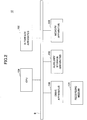
- Fig. 2 is a schematic diagram illustrating a hardware configuration of the management server 10 according to the first embodiment of the present invention
- the management server 10 of Fig. 2 includes, for example, a drive apparatus 100, an auxiliary storage apparatus 102, a memory apparatus 103, a CPU (Central Processing Unit) 104, and an interface apparatus 105 that are connected to each other by a bus B.
- a drive apparatus 100 for example, a drive apparatus 100, an auxiliary storage apparatus 102, a memory apparatus 103, a CPU (Central Processing Unit) 104, and an interface apparatus 105 that are connected to each other by a bus B.
- a bus B for example, a bus B.
- a program that implements the processes of the management server 10 is provided from a recording medium 101 such as a CD-ROM.
- the recording medium 101 having the program recorded therein is set to the drive apparatus 100, the program is installed from the recording medium 101 to the auxiliary storage apparatus 102 via the drive apparatus 100.
- the program does not necessarily have to be installed from the recording medium 101.
- the program may be downloaded to another computer via a network.
- the auxiliary storage apparatus 102 not only stores the installed program but also stores, for example, necessary files and data.
- the memory apparatus 103 reads out the program from the auxiliary storage apparatus 102 and stores the program therein.
- the CPU 104 executes the functions of the management server 10 in accordance with the program stored in the memory apparatus 103.
- the interface apparatus 105 is used as an interface to be connected to a network.
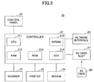
- Fig. 3 is a schematic diagram illustrating a hardware configuration of the image forming apparatus 20 according to the first embodiment of the present invention.
- the image forming apparatus 2 of Fig. 3 includes hardware such as a controller 21, a scanner 22, a printer 23, a modem 24, an operation panel 25, a network interface 26, and an SD card slot 27.
- the controller 21 includes, for example, a CPU 211, a RAM (Random Access Memory) 212, a ROM (Read Only Memory) 213, a HDD (Hard Disk Drive) 214, and a NVRAM (Non-Volatile RAM) 215.
- the ROM 213 stores, for example, various programs and data used by the programs therein.
- the RAM 212 may be used as a storage space to which programs are loaded or as a work space of the loaded programs.
- the CPU 211 implements various functions by performing the processes of the programs loaded to the RAM 212.
- the HDD 214 stores, for example, programs and data used by the programs therein.
- the NVRAM 215 stores, for example, data pertaining to various settings.
- the scanner 22 is a hardware device for reading image data from a document (image reading unit).
- the printer 23 is a hardware device for printing print data to a print document (printing unit).
- the modem 24 is a hardware device for connecting to a telephone line.
- the modem 24 is used for transmitting/receiving image data by way of facsimile communications.
- the operation panel 25 is a hardware device including, for example, an input unit for accepting input from the user or a display unit such as a liquid crystal panel.
- the liquid crystal panel may have a touch-panel function. In this case, the liquid crystal panel also provides the functions of an input unit.
- the network interface 26 is a hardware device for connecting to a network (by wireless, cable, or both) such as a LAN (Local Area Network).
- the SD (Secure Digital) card slot 27 is used for reading a program stored in a SD card 80. That is, not only is a program recorded in the ROM 213 but also a program recorded in the SD card 80 is loaded to the RAM 212, so that processes of the program can be executed by the image forming apparatus 20. It is to be noted that the SD card 80 may be replaced with other recording media (e.g., CD-ROM, USB (Universal Serial Bus) memory). That is, the type of recording media equivalent to the SD card 80 is not to be limited in particular. In this case, the SD card slot 27 may be replaced with hardware corresponding to the type of recording medium that is used.
- the image forming apparatus 20 may be provided without including the scanner 22 and the modem 24. That is, the image forming apparatus 20 may be a printer instead of a multifunction peripheral.
- Fig. 4 is a schematic diagram illustrating a functional configuration of a printing system according to the first embodiment of the present invention.
- the management server 10 of Fig. 4 includes, for example, a mail reception unit 11, an address confirmation unit 12, a PIN code generation unit 13, a print information generation unit 14, a response mail generation unit 15, a mail reply unit 16, and a print information transmission unit 17.
- the functions of these units included in the management server 10 are implemented by causing the CPU 104 to execute processes of the one or more programs installed in the management server 10.
- the management server 10 also includes a guest data storage unit 19.
- the functions of the guest data storage unit 19 are implemented by using, for example, the auxiliary storage device 102 or a storage device connected to the management server 10 via a network.
- the mail reception unit 11 receives print request mail.
- the print request mail includes target print data desired to be printed by the user (e.g., body text of electronic mail, file attached electronic mail).
- the user transmits an electronic mail including the target print data from the user terminal 30 to a mail address of a particular domain (transmission destination).
- the mail reception unit 11 recognizes that the electronic mail from the user terminal 30 is a print request mail by confirming that the address of the electronic mail is set with the particular domain.
- the address confirmation unit 12 transmits a request to confirm existence of a transmission source address of the print request mail to the authentication server 50 for determining whether the transmission source address is registered in the authentication server 50.
- the address confirmation unit 12 obtains a user name corresponding to the transmission source address from the authentication server 50.
- the PIN code generation unit 13 generates a PIN code.
- the print information generation unit 14 generates print information corresponding to the print request mail.
- the print information includes, for example, print data, data pertaining to a print job of the print data, the user name, and/or the PIN code.
- the response mail generation unit 15 generates an electronic mail in response to the print request mail (hereinafter also referred to as "response mail").
- the response mail includes, for example, identification data of a print data based on each print data.
- the response mail may also include, for example, a PIN code corresponding to a print request mail in the case where the PIN code is generated.
- the mail reply unit 16 transmits the response mail to the transmission source address of the print request mail.
- the print information transmission unit 17 stores the print information in the storage server 60 by transmitting the print information to the storage server 60.
- the guest data storage unit 19 stores data pertaining to a guest user.
- a guest user is a user that initially have authorization to use the printing system 1 but is allowed to use the printing system 1 as an exception.
- the authentication server 50 includes, for example, a request response unit 51 and a user data storage unit 52.
- the user data storage unit 52 stores user data with respect to each regular user.
- the request response unit 51 performs various processes in response to, for example, an authentication request, a request for confirming existence of a mail address, and a request for obtaining a user name corresponding to a mail address.
- the functions of the request response unit 51 are implemented by the processes executed by the CPU of the authentication server 50 in accordance with the program installed in the authentication server 50.
- the functions of the user data storage unit 52 are implemented by using, for example, an auxiliary storage device of the authentication server 50 or a storage device connected to the authentication server 50 via a network.
- the storage server 60 includes, for example, a print information reception unit 61, a print information storage unit 62, and a print information providing unit 63.
- the print information reception unit 61 receives print information transmitted from the management server 10, and stores (saves) the print information in the print information storage unit 62.
- the print information providing unit 63 transmits (returns) print information stored (saved) in the print information storage unit 62 to the image forming apparatus 20 in response to a request to obtain print information from the image forming apparatus 20.
- the print information transmitted to the image forming apparatus 20 is print information that includes a user name or a pin code designated in the print information obtain request.
- the functions of the print information reception unit 61 and the print information providing unit 63 are implemented by the processes executed by the CPU of the storage server 60 in accordance with one or more programs installed in the storage server 60.
- the functions of the print information storage unit 62 are implemented by using, for example, an auxiliary storage device of the storage server 60 or a storage device connected to the storage server 60 via a network.
- the image forming apparatus 20 includes, for example, an authentication control unit 221, a print information obtaining unit 222, and a print control unit 223.
- the functions of each of these units are implemented by the processes executed by the CPU 211 in accordance with one or more programs installed in the image forming apparatus 20.
- the authentication control unit 221 accepts a user name and a password input from the user. Alternatively, the authentication control unit 221 may also accept a PIN code input from the user. In a case where a user name and a password are input, the authentication control unit 221 requests the authentication server 50 to authenticate the input user name and password.
- the print information obtaining unit 222 transmits a request to obtain print information to the storage server 60.
- the request to obtain print information includes at least a user name or a PIN code designated (accepted) by way of the authentication control unit 221.
- the print control unit 223 performs a printing process on print data obtained by the print information obtaining unit.
- Fig. 5 is a sequence diagram for describing a sequence of processes for storing print data according to the first embodiment of the present invention.
- Step S101 the user terminal 30 transmits a print request mail to a predetermined mail address in response to an instruction input by the user.
- Electronic data that is to be printed (target print data) is attached to the print request mail.
- the predetermined mail address is, for example, a mail address designated beforehand as a mail address of the management server 10.
- the mail server 40 transfers the print request mail to the management server 10 according to a typical communication protocol used for transferring electronic mail (Step S102).
- the print request mail is received by a mail reception unit 11 of the management server 10.
- the management server 10 designates a transmission source address of the print request mail and transmits a request to confirm the existence of the designated address (existence confirmation request) (Step S103).
- the request response unit 51 of the authentication server 50 determines whether the designated address is stored in the user data storage unit 52 to confirm existence of the designated address (Step S104).
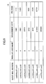
- Fig. 6 is a schematic diagram illustrating a configuration of the user data storage unit 52 according to an embodiment of the present invention.
- the user data storage unit 52 stores user data in correspondence with each regular user.
- the user data includes, for example, a user name, a password, and a mail address.
- Multiple mail addresses(e.g., PC address, mobile phone address) may be registered with respect to a single user.
- Step S104 the request response unit 51 determines whether the mail address designated in the existence confirmation request is included in the mail addresses of the user information stored in the user data storage unit 52.
- the request response unit 51 transmits (returns) a response including a confirmation result to the management server 10 (Step S105).
- the confirmation result is information indicating the existence of the designated mail address.
- the management server 10 In response to the received confirmation result, the management server 10 generates print information pertaining to the print request mail (Step S106). Then, the mail reply unit 16 of the management server 10 transmits a response mail in reply to the print request mail to the transmission source address of the print request mail (Step S107). The mail server 40 transfers the response mail to the user terminal 30 of the transmission source of the print request mail (Step S 108). It is to be noted that the response mail is generated in the process of generating the print information.
- the print information transmission unit 17 of the management server 10 transmits print information to the storage server 60 (Step S109).
- the print information transmitted to the storage server 60 includes, for example, print data generated in the print information generation process and other data associated to the print data.
- the print information storage unit 62 stores the received print information therein (Step S110).
- Fig. 7 is a schematic diagram illustrating a configuration of the print information storage unit 62 according to the first embodiment of the present invention.
- the print information storage unit 62 illustrated in Fig. 7 stores print information with respect to each print data.
- the print information includes, for example, job names, user mode, print data, user names, and PIN codes.
- the "job name” is identification data that corresponds to each print data or each print job executed for each print data.
- the "user mode” is data indicating whether the transmission source address of the print request mail is being managed in the user data storage unit 52. In this embodiment, the user mode indicates whether the user of the source of the print request is a regular user or a guest user. In Fig. 7 , the letter “U” indicates a regular user and the letter “G” indicates a guest user.
- the "user name” indicates the name of the user that is responsible for a print job based on the print information. The user responsible for a print job is, for example, a user that is to pay for the costs incurred by a print job.
- the "PIN code” indicates a PIN code assigned to the user in a case where the user is a guest user.
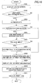
- Fig. 8 is a flowchart for describing a sequence of processes for generating print information according to the first embodiment of the present invention.
- Step S105 of Fig. 5 indicates the existence of the transmission source address of the print request mail (Yes in Step S201)
- the address confirmation unit 12 obtains the user name corresponding to the transmission source address from the authentication server 50 (Step S202). That is, a user name corresponding to the transmission source address is obtained from the user data storage unit 52.
- the print information generation unit 14 generates print data of the body text of the print request mail and print data of the electronic data attached to the print request mail (target print data) (Step S203).
- the target print data may be generated only from the electronic data attached to the print request mail.
- the print data generation unit 14 uncompresses the electronic data and generates print data in correspondence with each uncompressed file. Therefore, multiple print data (print jobs) may be generated from a single print request mail.
- the print information generation unit 14 generates print information for each print data (Step S204). That is, the print information generation unit 14 generates print information including a job name generated in correspondence with each print data. The letter "U" is set to the user mode in each print information. Further, the user name obtained in Step S202 is set with respect to each print information. The print information generated by the print information generation unit 14 is transmitted to the storage server 60 in Step S109 of Fig. 5 .
- the response mail generation unit 15 generates, for example, a response mail that includes a body text in which a job name of a corresponding print information is written (Step S205).
- the response mail is transferred to the user terminal 30 of the transmission source of the print request mail.
- the user that has received and browsed the response mail can identify the job name corresponding to each print data generated in correspondence with the print request mail transmitted from the user.
- the responses mail does not necessarily need to be transmitted to the user in a case where the transmission source address exists in the user data storage unit 52. This is because the user can recognize the content of print data corresponding to each job name during the below-described procedure of operating on the image forming apparatus 20 in a case where job names are generated based on file names or the like of electronic data.
- Step S105 of Fig. 5 indicates that the transmission source address of the print request mail does not exist (No in Step S201)
- the address confirmation unit 12 determines whether the transmission source address is a mail address of a guest user (Step S206). The determination is performed by referring to the guest data storage unit 19.
- Fig. 9 is a schematic diagram illustrating a configuration of a guest data storage unit 19 according to an embodiment of the present invention.
- the guest data storage unit 19 stores data in correspondence with each guest, For example, a guest mail address (mail address to be used by a guest), a regular user name, a management code, and a PIN code in correspondence with each guest.
- the guest mail address is a mail address of a transmission source that is used when the guest user transmits a print request mail. That is, the guest mail address is a mail address that is different from the mail address stored in the user data storage unit 52.
- the regular user name is, for example, a user name of a user responsible for a print job to be performed for a guest user.
- the management code is, for example, identification data indicating a regular user's division (department) of a company to be charged for the costs incurred by the print job of the guest user.
- the PIN code is a code generated for a guest user in the below-described Step S208. Therefore, in a case of a guest user that has never transmitted any print request mail in the past, there is no registered PIN code corresponding to the guest user.
- Each of the records of the guest data storage unit 19 corresponding to "guest mail address", "regular user name”, and "management code” may be registered by a single user (e.g., administrator).
- a regular user may register the records that are associated with the regular user name.
- the regular user logs in to the management server 10.
- the management server 10 may automatically register a user name of the regular user that has logged in to the management server 10 in association with a regular user name corresponding to the records to be registered to the guest data storage unit 19 by the regular user.
- each regular user can avoid the possibility of being associated to an unintended guest user mail address.
- Step S206 it is determined whether a transmission source address of the print request mail is registered as a guest mail address among the records of the guest data storage unit 19.
- the PIN code generation unit 13 In a case where the transmission source address is stored as a guest mail address in the guest data storage unit 19 (Yes in Step S206), the PIN code generation unit 13 generates a PIN code (S207).
- the guest user having its transmission source address registered as a guest mail in the guest data storage unit 19 is referred to as "target guest user”.
- the PIN code generation unit 13 stores the generated PIN code in correspondence with the transmission source address of the print request mail.
- a PIN code need not be newly generated in a case where a PIN code is already stored in the guest data storage unit 19.
- the stored PIN code need only be obtained from the guest data storage unit 19.
- the PIN code may be generated by using any method as long as the generated PIN code does not overlap with another guest user's PIN code stored in the guest data storage unit 19. It is, however, preferable for the PIN code to be constituted of letters that can be easily input by way of the operation panel 25 of the image forming apparatus 20 or a software keyboard displayed on the operation panel 25 of the image forming apparatus 20.
- Step S208 the print information generation unit 14 generates print data of a body text of the print request mail and print data of electronic data attached to the print request mail (target print data).
- the process performed in Step S208 may be the same as the process performed in Step S203.
- the print information generation unit 14 generates print information for each print data (Step S209). That is, the print information generation unit 14 generates print information including a job name generated in correspondence with each print data. The letter "G" is set to the user mode in each print information. Further, the regular user name stored in correspondence with the transmission source of the print request mail in the guest data storage unit 19 is set with respect to each print information. Further, the PIN code generated in Step S207 is also set with respect to each print information. The print information generated by the print information generation unit 14 is transmitted to the storage server 60 in Step S109 of Fig. 5 .
- the response mail generation unit 15 generates, for example, a response mail that includes a body text in which a job name and a PIN code of a corresponding print information is written (Step S210).
- the response mail is transferred to the user terminal 30 of the transmission source of the print request mail.
- the user that has received and browsed the response mail can identify the PIN code that is required to be input to the image forming apparatus 20 when printing the print data generated in response to the print request mail. Further, the user can also identify the job name corresponding to each print data. It is, however, to be noted that the job name does not necessarily need to be included in the response mail.
- the response mail transmitted in Step S210 may also be transmitted to the regular user associated with the guest user having a destination address to which the response mail is transmitted in Step S210.
- the user name of the regular user can be identified based on the guest data storage unit 19.
- the mail address corresponding to the user name of the regular user can be identified based on the user data storage unit 52.
- the response mail generation unit 15 generates, for example, a response mail including an error message (hereinafter also referred to as "error mail") (Step S211).
- error mail is transmitted (returned) in response to the print request mail in Step S110.
- the print information generation part 14 does not generate any print information. Therefore, Steps S112 and S113 of Fig. 5 are not executed. That is, the user is unable to print with the image forming apparatus 20.
- the mail address used as the transmission source address of the print request mail may be registered as the guest mail address to be stored in the guest data storage unit 19. In this case, it is determined whether the transmission source address of the print request mail is stored as a guest mail address among the records of the guest data storage unit 19 in Step S206.
- the mail address of the guest user is, in principle, registered beforehand. Then, the guest user transmits a print request mail having the guest user's mail address as the transmission source of the print request mail. This ensures uniqueness in which a single guest user can be identified by a single PIN code. Further, there is also an advantage of being able to use the same PIN code for transmitting print request mail with the same mail address (except for a case where multiple users are able to use a single mail address). It is, however, necessary to register personal information of the guest user such as a mail address in correspondence with each guest user.
- the guest mail address stored in the guest data storage unit 19 is set as the mail address of a transmission destination
- one or more guest addresses are, in principle, distributed to and registered in correspondence with a single regular user.
- the regular user can teach the guest address to the guest, so that the guest can transmit a print request mail having the guest address as its transmission destination (destination address).
- a PIN code corresponding to a guest mail address is shared by multiple guest users
- print data of another guest user may be unintentionally printed in a case where multiple guest users use the same single guest mail address (e.g., in a case where there are multiple visitors). Therefore, in this case, a unique PIN code corresponding to a single print request mail is to be generated or a unique PIN code corresponding to a transmission source address is to be generated and managed.
- the mail address to be used as the guest mail address may be decided depending on how a company or user operates. It is preferable to manage the guest mail addresses of each record of the guest data storage unit 19 by associating the guest mail addresses with identification data that indicate whether a guest mail address is a transmission source address or a transmission destination address. Thereby, the degree of freedom of the determination in Step S206 can be increased determining whether a transmission source address or a transmission destination address is a mail address of the guest user based on identification data.
- the user goes to the area where the image forming apparatus 20 is installed (placed) and operates the image forming apparatus 20.
- a procedure of processes performed by the image forming apparatus 20 in response to the operation of the user is described.
- Fig. 10 is a flowchart illustrating a procedure of processes performed by the image forming apparatus 20 according to an embodiment of the present invention.
- the authentication control unit 221 displays a log-in screen on the operation panel 25 (Step S301).
- Fig. 11 is a schematic diagram illustrating an example of a log-in screen 510 displayed on the operation panel 25 according to an embodiment of the present invention.
- the log-in screen 51 includes input areas for inputting, for example, a user name, a password, and a PIN code,
- a user name and a password are input to the log-in screen 510.
- a PIN code which is reported (notified) to the guest user by way of a response mail, is input to the log-in screen 510
- the PIN code may be input even in a case where the operator of the image forming apparatus 20 is a regular user.
- the regular user transmits a print request mail from a mail address that is not stored in the user data storage unit 52 (e.g., a case where the regular user transmits a print request mail from a mail address of a user terminal 30 personally used by the regular user)
- a response mail transmitted to the user terminal 30 in response to the print request mail includes a PIN code.
- the regular user transmits a print request mail from another mail address that is stored in user data storage unit 52.
- both print data associated with the PIN code and print data associated with the user name of the regular user are stored with respect to the regular user in the storage server 60.
- the PIN code may also be input at the same time of inputting the user name and the password of the regular user.
- the authentication control unit 221 determines whether a user name or a password is input to the log-in screen 510 (Step S302). In a case where the user name and the password are input (Yes in Step S302), the authentication control unit 221 performs an authentication process (S303). More specifically, the authentication control unit 221 transmits an authentication request including a designated user name and password to the authentication server 50. The request response unit 51 of the authentication server 50 determines whether a set of the designated user name and the password included in the authentication request is stored in the user data storage unit 52.
- the authentication process is a success. In a case where the set is not stored in the user data storage unit 52, the authentication process is a failure.
- the request response unit 51 transmits data indicating success/failure of the authentication process to the authentication control part 221 of the image forming apparatus in response to the authentication request transmitted from the authentication control part 221.
- Step S305 the print information obtaining unit 222 add the user name input to the log-in screen 510 to designation data.
- designation data is data that is designated in the below-described Step S308 for obtaining a list of print information from the storage server 60.
- Step S305 is not performed.
- the print information obtaining unit 222 determines whether a PIN code is input to the log-in screen 510 (Step S306). In a case where a PIN code is input (Yes in Step S306), the print information obtaining unit 222 adds the PIN code to designation data (S307). In a case where a PIN code is not input (No in Step S306), Step S307 is not performed.
- the print information obtaining unit 222 designates designation data and obtains a list of print information from the storage server 60 (Step S308). More specifically, the print information obtaining unit 222 designates designation data and transmits a request to obtain a list of print information including the designated designation data to the storage server 60. In response to the request from the print information obtaining unit 222, the print information providing unit 63 of the storage server 60 obtains print information including the designated designation data from the print information storage unit 62 (see Fig. 7 ). That is, in a case where a user name and a password are input to the log-in screen 510, the obtained print information includes a user mode indicated as "U" and a user name matching the input user name.
- the obtained print information includes a user mode indicates as "G" and a PIN code matching the input PIN code.
- print information obtained in response to a print request mail from a guest user includes a user name of a regular user (regular user name) associated with the guest user, Therefore, in a case where a user name and a password are input to the log-in screen 510, there is a case where the obtained print information includes a user mode indicated as "G" and a user name matching the input user name.
- the regular user can instruct the image forming apparatus 20 to perform a printing process on a print job based on a print request mail transmitted from a guest user.
- the regular user can substitute for the guest user for instructing a print job.
- a user name and a password are input to the log-in screen 510, it is possible to prohibit obtaining of print information including a user mode indicated as "G" and the user name matching an input user name if there is a priority for protecting confidential data included in a print request mail transmitted from a guest user.
- both print information including a user mode "U” and the input user name and print information including a user mode "G” and the input PIN code are obtained. If the authentication process is a failure in a case where both the set of user name/ password and the PIN code are input to the log-in screen 510, print information including a user mode "G" and the input PIN code is obtained.
- the print information providing unit 63 transmits a list of the obtained print information to the image forming apparatus 20. It is to be noted that the transmitted print information does not need to contain print data.
- the print information obtaining unit 222 of the image forming apparatus 20 displays, for example, a list of print jobs included in the transmitted print information on the operation panel (Step S309).
- the list includes candidates of data to be printed (target print data). That is, the user can input an instruction for performing a printing process based on the print information included in the list.
- the print information obtaining unit 222 obtains print data corresponding to the one or more selected print jobs from the storage server 60 (Step S310). More particularly, the print information obtaining unit 222 transmits a request to obtain print data corresponding to a designated print job to the storage server 60. In response to the request, the print information providing unit 63 of the storage server 60 transmits print data corresponding to the designated print job included in the request to the image forming apparatus 20.
- the print information corresponding to the designated print job may also be hereinafter referred to as "target print information”.
- the print information obtaining unit 222 obtain print data without performing the process of Step S309. Further, the print information providing unit 63 may transmit information data obtained according to the input user name or PIN code to the image forming apparatus 20 instead of transmitting the list of print information to the image forming apparatus 20.
- a log indicating the execution of the print job may include a user name included in the target print information.
- a user name is included even in a case where the user mode of the print information is indicated as "G". That is, in this embodiment, the user name is included in both print information including the user mode "U” and print information including user mode "G".
- a billing destination that is to be billed i.e.
- the billing destination for the payment can be determined even for a print job indicated with a user mode "G". It is to be noted that identification data of the billing destination and a corresponding user name may be stored in, for example, the HDD 214.
- Step S311 if the target print information is indicated with a user mode "U" (i.e. a case where the operator of the image forming apparatus 20 is a regular user), the print control unit 223 executes the print job within the range of authority (print authority) corresponding to the user name input during the log-in operation, On the other hand, if the target print information is indicated with a user mode "G" (i.e. a case where the operator of the image forming apparatus 20 is a guest user), the print control unit 223 executes the print job within the range of authority of the regular user associated with the guest user. Alternatively, the print job may be executed within a range of authority corresponding to the guest user. It is to be noted that the authority of each user may be stored in the guest data storage unit 19. The authority of guest user may be shared by multiple guest users or different from one another.
- a print authority may be granted to the guest user. Therefore, the necessity for the guest user to request the regular user to print data can be reduced. Further, a PIN code is reported (notified) to a guest user in response to each print request mail from the guest user. Therefore, a virtual temporary account can be provided to each guest user.
- print data that can be operated by each of the guest users is limited to print data corresponding to a print request mail from each of the guest users. This prevents print data of a guest user from being easily operated by other guest users.
- the guest user may be stored in the guest data storage unit 19 in correspondence with one of the regular users beforehand.
- a regular user can be associated with respect to a print job requested by the guest user.
- the billing destination that is to pay for the cost incurred by the print job can be determined based on the association between the guest user and the corresponding regular user.
- the regular user may transmit a print request mail from a mail address that is different from a mail address stored in correspondence with the regular user.
- the regular user can be prevented from being mistaken for a guest user. That is, as long as a mail address designated as a transmission source address of a print request mail is stored as a guest mail address in correspondence with a name of a regular user in the guest data storage unit 19, execution of a print job can be permitted in accordance with the print request mail. Further, the billing destination of the cost incurred by the print job can be determined in accordance with the print request mail.
- the log-in screen 510 may be displayed to enable input of multiple PIN codes.
- the print information obtaining unit 222 may obtain print information including any one of the multiple PIN codes from the storage server 60. By doing so, a complicated process of having to repeat a log-in operation or displaying of the list of print information with respect to each of the multiple PIN codes can be prevented.
- the PIN code generation unit 13 of the management server 10 may store a generated PIN code in correspondence with a transmission source address of a print request mail in, for example, the auxiliary storage apparatus 102.
- the PIN code generation unit 13 may output the stored PIN code without having to generate a new PIN code, In this case, a response mail including the stored PIN code is transmitted in response to the print request mail.
- the guest user can instruct the image forming apparatus 20 to display a list of print information corresponding to the multiple print request mails or print the print information by inputting the PIN code to the log-in screen 510.
- the image forming apparatus 20 may set a limitation in a case of printing print data corresponding to print information obtained by designation of a PIN code.
- the limitation may be, for example, an upper limit in the number of sheets that can be printed or a limitation preventing the performing of a color printing process. By doing so, the guest user is prevented from performing a large amount of printing.
- a validity date may be set to a PIN code.
- a PIN code having an expired validity date may be invalidated.
- the second embodiment is explained with an example in which the functions of the management server 10, the authentication server 50, and the storage server 60 are provided by way of the Internet similar to that of a cloud service. Therefore, in the second embodiment, the Internet is provided between the user terminal 30, the mail server 40, and the management server 10, and between the image forming apparatus 20, the authentication server 50, and the storage server 60.
- Fig. 12 is a schematic diagram illustrating a configuration of functions of the printing system 1 according to the second embodiment of the present invention.
- the management server 10 includes an address correspondence data storage unit 18.
- the address correspondence data storage unit 18 stores mail addresses that are assigned to each user company (company serving as a user) and addressed to the management server 10.
- the address correspondence data storage unit 18 is implemented by using, for example, the auxiliary storage apparatus 102 or a storage device connected to the management server 10 via a network.
- the storage server 60 includes a user device information storage unit 64.
- the user device information storage unit 64 stores identification data (hereinafter also referred to as "device ID") of each image forming apparatus 20 installed in correspondence with each user company,
- Step S101 the user terminal 30 designates a predetermined mail address of the management server 10 and transmits a print request mail to the predetermined mail address of the management server 10.
- the predetermined mail address of the management server 10 is assigned to each user company to which a target image forming apparatus 20 belongs (i.e. image forming apparatus that is to perform printing). That is, the predetermined mail address of the management server 10 is assigned to each user company at which the target image forming 20 is installed.
- the mail reception unit 11 of the management server 10 determines which user company's image forming apparatus 20 is designated to be the target image forming apparatus 20 based on the mail address in which the print request mail has been received. That is, the mail reception unit 11 determines the target image forming apparatus 20 based on the mail address designated to be the destination of the print request mail. The determination is performed by using the address correspondence data storage unit 18.
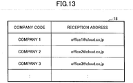
- Fig. 13 is a schematic diagram illustrating a configuration of the address correspondence data storage unit 18 according to an embodiment of the present invention.
- the address correspondence data storage unit 18 stores, for example, company codes and reception addresses in correspondence with each user company.
- the company code is an identification data assigned to each user company.
- the reception address is a mail address destined for the management server 10 and is assigned to each user company. From the standpoint of the management server 10, the reception address is a mail address or a part of a mail address for receiving a print request mail from a corresponding user company.
- the mail reception unit 11 stores a company code corresponding to a mail address that has received a print request mail.
- the company code is stored in, for example, the memory apparatus 103. Accordingly, in Step S109, print information including a company code is transmitted to the storage server 60.
- the print information reception unit 61 of the storage server 60 receives the print information from the management server 10, the print information storage unit 62 stores the received print information therein (Step S110).
- Fig. 14 is a schematic diagram illustrating a configuration of a print information storage unit 62 according to the second embodiment of the present invention. As illustrated in Fig. 14 , the print information storage unit 62 of the second embodiment also stores company codes in correspondence with each print data. It is to be noted that the print information storage units 62 may be separately provided in correspondence with each company code.
- the user that has transmitted the print request mail goes to the area where the image forming apparatus 20 is installed (placed) and operates the image forming apparatus 20.
- a procedure of processes performed by the image forming apparatus 20 in response to the operation of the user is described,
- Step S206 of Fig. 8 the address confirmation unit 12 determines whether a transmission source address of a received print request mail is a guest user mail address by referring to the guest data storage unit 19 to search for a company code corresponding to a mail address matching the transmission source address of the print request mail.
- the procedure of processes performed by the image forming apparatus 20 in the second embodiment is basically the same as the procedure of processes illustrated in Fig. 10 . However, a part of the steps of the processes of the second embodiment is different from the steps of the processes of the first embodiment. More specifically, in Step S308, the print data obtaining unit 22 designates designation data including a company code and a device ID in addition to other designated data and transmits a request to obtain a list of print information including the designated designation data to the storage server 60.
- the device ID is a device ID of the image forming apparatus 20 that is to perform printing.
- the device ID is stored in, for example, the ROM 213, the NVRAM 215, or the HDD 214 of the image forming apparatus 20.
- the company code is a code of the company at which the image forming apparatus 20 is installed.
- the company code is set to the image forming apparatus 20 beforehand.
- the company code that is set to the image forming apparatus 20 may be stored in, for example, the NVRAM 215 or the HDD 214.
- the device ID may be stored in the form of a specific application installed in the image forming apparatus 20.
- the image forming apparatus 20 having the specific application installed therein may be identified based on the device ID. That is, in this embodiment, as long as the image forming apparatus 20 can be determined as the image forming apparatus 20 having the specific application installed therein, an identifier or the like of the specific application may be used as the device ID.
- the print information providing unit 63 of the storage server 60 determines whether a set of the company code and the device ID included in a designation data of a print information obtain request is stored in the user device data storage unit 64.
- Fig. 15 is a schematic diagram illustrating a configuration of the user device data storage unit 64 according to an embodiment of the present invention.
- the user device data storage unit 64 associates the company code of the user company with the device ID of the image forming apparatus 20 and stores the associated company code and the device ID in correspondence with each of the image forming apparatuses 20 installed in the user company.
- the print information providing unit 63 does not transmit a list of print information. This is because the image forming apparatus 20 (transmission source) that has transmitted the request to obtain print information is likely to lack validity.
- the validity of an image forming apparatus is an indication that the image forming apparatus 20 is installed in an appropriate user company,
- the print information providing unit 63 obtains print information including the designation data in the request to obtain print information from the print information storage unit 62 (see Fig. 14 ). That is, in the second embodiment, print information, which also includes a company code matching the company code included in the designation data, is obtained from the print information storage unit 62. Then, the print information providing unit 63 transmits a list of the obtained print information to the image forming apparatus 20.
- the print information providing unit 63 may refer to the device ID included in the designation data and identify the company code corresponding to the device ID based on the user device information storage unit 64 and used the identified company code to obtain print information from the print information storage unit 62.
- the mail addresses destined for the management server 10 are different for each user company. Further, a company code is identified with respect to a request to obtain a list of print information from the image forming apparatus 20. In response to the request from the image forming apparatus 20, the list of print information including the company code is transmitted to the image forming apparatus 20. Accordingly, even in a case where print request mails are transmitted from users having the same user name from different user companies, print information requested from one company can be prevented from becoming a printing candidate in response to a print request mail from another company.
- a company code can be identified by managing the mail addresses of regular users in association with company codes. Further, in a case where a mail address of a transmission source of a print request mail is a mail address of a guest user, a company code can be identified based on the mail addresses of regular users associated with guest users. Therefore, mail addresses destined for the management server 10 does not necessarily need to be provided for each user company.
- a mail address of the management server 10 may itself be used as a company code for each user company.
- the user device data storage unit 64 need not be provided.
- the mail address of the management server 10 is included in print information and stored in the storage server 60. Further, the mail address of the management server 10 is stored beforehand in the image forming apparatus 20.
- the image forming apparatus 20 transmits a request to obtain a list of print information including a device ID and a designated mail address of the management server 10 to the storage server 60.
- the storage server 60 transmits a list of print information including the mail address of the management server 60 designated in the request.
- the third embodiment is explained with an modified example of processes performed during user authentication with the image forming apparatus 20.
- a user name, a password or a PIN code are input to the log-in screen 510.
- the user is to input the user name, the password, or PIN code by using a keyboard or the like.
- the image forming apparatus 20 of the third embodiment is provided with a noncontact type card reader.
- the user terminal 30 used by the user is a portable type terminal including the same IC chip as an IC chip of an IC card. For example, a user name and a password of a user are stored in a storage unit of the user terminal 30.
- the user terminal 30 includes an application that is to be transmitted to the image forming apparatus 20 via the card reader of the image forming apparatus 20 in a case where the user name and the password are read out from the storage unit of the user terminal 30 when the user terminal 30 is placed over the card reader of the image forming apparatus 20.
- the authentication control unit 221 of the image forming apparatus 20 performs an authentication process by using the user name and the password received by the card reader.
- authentication of the regular user can be performed by placing the regular user's user terminal 30 over the image forming apparatus 20.
- a response mail including a PIN code is transmitted in response to a print request mail transmitted from the user terminal 30. Then, the response mail is stored in a storage unit of the user terminal 30. Accordingly, the above-described application included in the user terminal 30 may be implemented to search for an electronic mail (i.e. response mail) having a predetermined mail address as the transmission source address in the user terminal 30 when the user terminal 30 is placed over the card reader of the image forming apparatus 20.
- the PIN code included in the electronic mail may be transmitted to the image forming apparatus 20 via the card reader.
- the print information obtaining unit 222 of the image forming apparatus 20 may designate the PIN code received from the card reader and obtain print information.
- the guest user can browse a list of print information associated with a PIN code assigned to the guest user by placing the guest user's user terminal 30 over the image forming apparatus 30.
- the image forming apparatus 20 may obtain the user name, the password, and the PIN code and obtain print information corresponding to the user name as well as print information corresponding to the PIN code.
- the present invention is not limited to printing.
- the present invention may be applied to a case of projecting image data from a projector. That is, the present invention may also be applied to a case where target print data is replaced with target output data that is output by way of displaying with a terminal or projecting with a projector.
- the target print data may be transmitted to the management server 10 by using other methods of communications.
- the management server 10 receives target print data and data pertaining to a user name of a regular user or target print data and data pertaining to a mail address of a guest user from the user terminal 30.
- the management server 10 generates a PIN code and transmits the generated PIN code to the user terminal 30.
- the management server 10 receives data pertaining to a company code from the user terminal 30 in addition to receiving target print data along with data pertaining to a user name of a regular user or receiving target print data along with data pertaining to a mail address of a guest user.
- the management server 10 transmits a notice to the user terminal 30 indicating that printing of target print data is denied.
- the management server 10 In a case where there is a matching company code and a mail address of a guest user is stored in the guest data storage unit 19 in correspondence with a user name of a regular user, the management server 10 generates a PIN code and transmits the generated PIN code to the user terminal 30.
- a single computer may be used to serve as both the management server 10 and the storage server 60 in the above-described embodiments of the present invention.
- a single computer may be used to serve as the management server 10, the storage server 60, and the authentication server 50.
- the functions of the management server 10, the storage server 60, and the authentication server 50 may be provided in the image forming apparatus 20.
- multiple computers may be used for each of the management server 10, the storage server 60, and the authentication server 50.
- print data are generated by the management server 10
- the generation of print data pertaining to the electronic data attached to the print request mail may be implemented by one or more of the user terminal 30, the management server 10, the storage server 60, and the image forming apparatus 20.
- the fourth embodiment is a modified example of the second embodiment.
- Fig. 16 is a schematic diagram illustrating a configuration of a system according to the fourth embodiment.
- like components are denoted with like reference numerals as the reference numerals of Fig. 1 and are not further explained.
- a service providing system 70 and a user environment E1 can communicate with each other via a wide area network such as the Internet.
- the service providing system 70 is a computer system that provides a cloud service via a network. It is be noted that, although this embodiment is described using an example of a cloud service, this embodiment may also be applied to various other services provided via a network such as a service provided by a ASP (Application Service Provider) or a Web service.
- ASP Application Service Provider
- the service providing system 70 includes, for example, an access control apparatus 75, a print service providing apparatus 711, a service A providing apparatus 712, a service B providing apparatus 713, a common service providing apparatus 72, and a database apparatus 73.
- Each of the apparatuses included in the service providing system 70 may be implemented by a single computer.
- the access control apparatus 75 controls access to computers inside the service providing system 70.
- the access control apparatus 75 also scatters (decentralizes) the workload of the computer inside the service providing system 70.
- the print service providing apparatus 711 includes one or more computers that control the processes for providing a cloud printing service.
- the cloud printing service is a service that allows print data to be uploaded to a cloud environment (in this embodiment, the service providing system 70) and printed by the image forming apparatus 20 according to necessity.
- the service A providing apparatus 712 and the service B providing apparatus 713 are examples of computers that provide services other than the cloud printing service.
- the common service providing apparatus 72 includes one or more computers providing functions shared by apparatuses (e.g., print service providing apparatus 711, service A providing apparatus 712, service B providing apparatus 713) that directly provide a particular service via a network.
- apparatuses e.g., print service providing apparatus 711, service A providing apparatus 712, service B providing apparatus 713
- the one or more computers of the common service providing apparatus 72 may also provide functions used by multiple apparatuses.
- the database apparatus 73 includes one or more computers or storage devices that function as various storage units.
- the user environment E1 is a system environment of an organization (e.g., user company) which is a user of the service providing system 70.
- the user environment E1 illustrated in Fig. 16 includes, for example, an image forming apparatus 20a, an image projection apparatus 20b, a portable terminal 20c, other output apparatuses 20d, and the user terminal 30.
- the apparatuses and terminals included in the user environment E1 are connected to each other by a network (wireless or wired) such as LAN (Local Area Network).
- LAN Local Area Network
- the image forming apparatus 20a is substantially the same as the image forming apparatus 20 of the second embodiment.
- the image projection apparatus 20b is, for example, a projector that projects image data.
- the portable terminal 20c is, for example, a PDA (Personal Digital Assistant), a tablet-type terminal, a smartphone, or a mobile phone.
- the other output apparatus are output apparatus other than those described above.
- the user environment E1 also includes a firewall F1.
- the firewall F1 may be the same as a typically used firewall.
- the firewall F1 blocks request from outside the user environment E1.
- the service providing system 70 may be accessed from environments other than the user environment E1.
- the portable terminal 20e or the PC 20f may access the service providing system 70 via the Internet.
- the portable terminal 20e and the PC 20f may be used inside the user environment E1.
- Fig. 17 is a schematic diagram illustrating functions of the service providing system 70 according to the fourth embodiment of the present invention.
- the functions of the service providing system 70 of Fig. 17 may be categorized by, for example, an application layer 71L, a common service layer 72L, and a database layer 73L.
- the application layer 71L is a layer installed with applications used by a server for cooperating with other devices such as the image forming apparatus 20a (hereinafter also referred to as "server application").
- the application layer 71L of Fig. 17 includes, for example, a print service application 711a, a service A application 712a, and a service B application 713a.
- the print service application 711a is a server application pertaining to a cloud printing service.
- the print service application 711a is installed in the print service providing apparatus 711.
- the service A application 712a and the service B application 713a are examples of other server applications.
- the service A application 712a and the service B application 713a are installed in the service A providing apparatus 712 and the service B providing apparatus 713, respectively.
- the common service layer 72L is a layer including, for example, functions shared by multiple server applications or basic functions used by multiple server applications.
- the functions of the common service layer 72L can be called via a platform API (Application Programming Interface) 74.
- the platform API 74 is basically called from the service applications installed in the application layer 71L. It is to be noted that the platform API 74 may be publicized with respect to, for example, a third vendor other than an administrator of the service providing system 70. In this case, server applications may be installed by the third vendor. That is, service applications may be developed and added by using the platform API 74.
- the common service layer 72L of Fig. 17 includes, for example, a user authentication unit 721, a device authentication unit 722, a management data obtaining unit 723, a mail obtaining unit 724, a device communication unit 725, a PIN code issue unit 726, a PIN code management unit 727, and a data conversion unit 728.
- the user authentication unit 721 authenticates a user.
- the device authentication unit 722 authenticates a corresponding relationship between the image forming apparatus 20a, a user, and an organization.
- the term "organization” may include, for example, a company of the above-described embodiments and other organizations. It is to be noted that, identification data corresponding to "company code” in the second embodiment is referred to as “organization code” in the fourth embodiment. Therefore, the authentication of the corresponding relationship between the user and the organization includes a process of determining (inspecting) whether the user and the image forming apparatus 20 belong to a corresponding organization.
- the management data obtaining unit 723 obtains, for example, data stored in the database layer 73L in response to a request from the application layer 71L.
- the mail obtaining unit 724 obtains (receives) electronic mail stored in the mail server 40 in accordance with POP (Post Office Protocol) or the like.
- the device communication unit 725 performs communications between various devices.
- the PIN code issue unit 726 issues (generates) PIN codes.
- the PIN code management unit 727 manages PIN codes in correspondence with organization codes.
- the data conversion unit 728 converts data formats. In this embodiment, the data conversion unit 728 generates print data based on target print data.
- one or more programs which are installed in the computers constituting the service providing system 70, cause the computers to execute various processes, to thereby implement each of the server applications of the application layer 71L and the components of the common service layer 72L.
- the database layer 73L is a layer including a database (storage unit) that stores various data therein.
- the database layer 73L is implemented by using the database apparatus 73.
- the database layer 73L of Fig. 17 includes, for example, an address correspondence data storage unit 731, a user device data storage unit 732, a user data storage unit 733, a print data storage unit 734, and a guest data storage unit 735.
- the address correspondence data storage unit 731 has substantially the same configuration as the configuration of the address correspondence data storage unit 18 (see Fig. 13 ).
- the user device data storage unit 732 has substantially the same configuration as the configuration of the user device data storage unit 64 (see Fig. 15 ).
- the user data storage unit 733 has a similar configuration as the user data storage unit 52 (see Fig. 6 ). The difference between the user data storage unit 733 and the user data storage unit 52 is described below.
- the print data storage unit 734 has substantially the same configuration as the configuration of the print data storage unit 62 (see Fig. 7 ).
- the guest data storage unit 735 has substantially the same configuration as the configuration of the guest data storage unit 19 (see Fig. 9 ). However, unlike the guest data storage unit 19, the guest data storage unit 735 is provided for each organization code.
- each of the applications (software) and storage units illustrated in Fig. 17 is merely one example.
- Each of the applications (software) and storage units of the service providing system 70 does not necessarily need not be categorized into layers as illustrated in Fig. 17 for implementing the fourth embodiment of the present invention. That is, the layer relationship or the like of the applications (software) and storage units of the service providing system 70 are not to be limited in particular as long as the procedure of processes of the fourth embodiment can be executed.
- Fig. 18 is a schematic diagram illustrating a functional configuration of the user terminal 30 and the print service application according to the fourth embodiment of the present invention.
- a Web browser 31 is a typical Web browser.
- a mail transmission unit 32 transmits electronic mail. In this embodiment, the mail transmission unit 32 transmits a print request mail. It is to be noted that the mail transmission unit 32 is implemented by causing the user terminal 30 to execute processes of a program referred to as a "mailer".
- the print service application 711a includes, for example, a mail analysis unit 81, an organization code identification unit 82, a user name identification unit 83, a print information generation unit 84, a response mail generation unit 85, a mail reply unit 86, and a print information providing unit 87.
- the mail analysis unit 81 analyzes a print request mail and extracts data (e.g., target print data) from the print request mail.
- the organization code identification unit 82 identifies an organization code corresponding to a transmission source address of a print request mail.
- the user name identification unit 83 identifies a user name corresponding to a transmission source address of a print request mail.
- the functions of the print information generation unit 84, the response mail generation unit 85, the mail reply unit 86, and the print information providing unit 87 are substantially the same as the functions of the print information generation unit 14, the response mail generation unit 15, the mail reply unit 16, and the print information providing unit 63 of Fig. 12 .
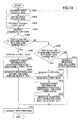
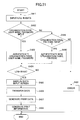
- Fig. 19 is a flowchart illustrating a procedure of processes performed for registering print information based on a print request mail according to an embodiment of the present invention.
- Step S401 the mail transmission unit 32 of the user terminal 30 transmits a print request mail in accordance with an instruction input by a user.
- the print request mail is transmitted to an mail address assigned to an organization to which the user belongs,
- the contents of the print request mail is the same as those of the above-described embodiments of the present invention.
- the mail obtaining unit 724 of the service providing system 70 obtains the print request mail from the mail server 40 (Step S402). Then, the mail analysis unit 81 of the print service application 711a extracts a target print data from the print request mail (Step S403). Then, the organization code identification unit 82 of the print service application 711a identifies an organization code corresponding to the print request mail based on the destination address of the print request mail and the address correspondence data storage unit 731 (Step S404). That is, the organization code identification unit 82 obtains a corresponding organization code from the address correspondence data storage unit 731 that stores organization codes in association with destination addresses.
- the configuration of the address correspondence data storage unit 731 may be substantially the same as the configuration of the address correspondence data storage unit 64 (see Fig. 15 ). It is, however, to be noted that "company code" of the address correspondence data storage unit 64 is to be replaced with "organization code” in the fourth embodiment.
- the user name identification unit 83 of the print service application 711a determines whether it is possible to identify a user name of a regular user corresponding to the transmission source address of the print request mail by referring to the user data storage unit 73 (Step S405). More specifically, the user name identification unit 83 determines whether the transmission source address of the print request mail corresponding to the organization code identified in Step S404 (hereinafter also referred to as "target organization code”) is stored in the user data storage unit 733.
- target organization code hereinafter also referred to as “target organization code
- Fig. 20 is a schematic diagram illustrating a configuration of the user data storage unit 733 according to the fourth embodiment of the present invention.
- the user data storage unit 733 of Fig. 20 also includes data items "organization code” and "role”.
- the data item "role" is data for distinguishing whether each user is an administrator or a user.
- An administrator is an administrator of devices (e.g., image forming apparatus 20a) that coordinate with the service providing system 70. The administrator performs operations for coordinating the service providing system 70 with devices such as the image forming apparatus 20a.
- the user is a user that uses the services provided by the service providing system 70.
- Step S405 it is determined whether user data including the target organization code and the transmission source address exists among the user data stored in the user data storage unit 733.
- the user name included in the user data (hereinafter also referred to as "target user name”) is identified.
- Step S405 the data conversion unit 728 of the service providing system 70 generates print data pertaining to the target print data (Step S406). It is to be noted that in a case where the target print data has a format that allows the target print data to be printed without data conversion, the process of generating print data may be omitted.
- the print data generation unit 84 generates print information (Step S407).
- the generated print information includes, for example, a job name, a target organization code, a target user name, and print data.
- the print information generation unit 84 stores the generated print information in the print information storage unit 734,
- the response mail generation unit 85 of the print service application 711a generates a response mail (Step S408).
- the response mail includes, for example, a job name.
- the mail reply unit 86 transmits the response mail to the transmission source address of the print request mail (Step S415).
- the user name identification unit 83 determines whether the user name of the regular user corresponding to the transmission source address can be identified by using the guest data storage unit 735 (Step S409). More specifically, the user name identification unit 83 determines whether a record having the transmission source address as its guest mail address is included in the guest data storage unit 735. In a case where a corresponding record is stored in the guest data storage unit 735, the user name of the regular user corresponding to the record is identified as the target user name.
- Step S410 the PIN code issue unit 726 of the service providing system 70 generates a PIN code (Step S410).
- the processes performed in and after Step S411 are substantially the same the processes performed on and after Step S407.
- the print information generated in Step S412 includes, for example, a job name, an organization code, a target user name, a PIN code, and print data. Further, in Step S413, a response mail including a PIN code and a job name is generated.
- the response mail generation unit 15 In a case where the user name of the regular user cannot be identified even by using the guest data storage unit 735 (No in Step S409), the response mail generation unit 15 generates a response mail including an error message (hereinafter also referred to as "error mail") (Step S414). Then, in this case, the generated error mail is transmitted in Step S415. Further, in this case, print information is not generated. Therefore, the processes performed in Steps S109 and S110 of Fig. 5 are not performed. That is, the user is unable to perform printing.
- error mail an error message
- print information may be registered with a method other than transmitting a print request mail.
- Fig. 21 is a flowchart for describing a sequence of processes for registering print information by using a Web interface according to an embodiment of the present invention.
- a screen for logging in to the service providing system 70 is displayed on the Web browser 31 of the user terminal 30.
- Step S421 the Web browser 31 accepts (receives) input of log-in data from the user via a log-in screen.
- Fig. 22 is a schematic diagram illustrating a log-in screen 520 displayed on a user terminal according to the fourth embodiment of the present invention.
- the log-in screen 520 illustrated in Fig. 22 includes input areas for inputting, for example, an organization code, a user name, a password, and a PIN code.
- the log-in screen 520 also includes, for example, an OK button and a PIN issue button.
- the first pattern is to designate an organization code, a user name, and a password (pattern 1).
- the second pattern is to designate an organization code and a PIN code (pattern 2).
- pattern 2 a PIN code is to be issued to the user beforehand.
- the PIN issue button 522 is to be pressed for having a PIN code issued to the user. The procedure of processes performed when the PIN issue button 522 is pressed is described below.
- the Web browser 31 determines whether an organization code, a user name, and a password have been input to the log-in screen 520 (Step S422). It is to be noted that the processes performed by the Web browser 31 are based on definitions of a Web page (e.g., HTML (HyperText Markup Language) of the log-in screen 520 displayed by the Web browser 31.
- a Web page e.g., HTML (HyperText Markup Language) of the log-in screen 520 displayed by the Web browser 31.
- the Web browser 31 receives authentication by the service providing system 70 based on the input organization code, user name, and password (S423). More specifically, the input organization code, user name, and password are transmitted to the user authentication unit 721. Then, the user authentication unit 721 performs authentication by determining whether the set of the input organization code, user name, and password is stored in the user data storage unit 733.
- the Web browser 31 displays a data input screen (S425).
- the data input screen is a screen for allowing the user to select a file to be printed from the files stored in the user terminal 30.
- data stored in the selected file is transferred from the Web browser 31 to the service providing system 70 (Step S426).
- Step S427, S428) print information including print data that is based on the received data is stored in the print data storage unit 734.
- the Web browser 31 determines whether data input to the log-in screen 520 are an organization code and a PIN code (Step S429).
- the Web browser 31 receives authentication by the service providing system 70 based on the input organization code and PIN code (S430). More specifically, authentication is performed by determining whether the set of the input organization code and PIN code is stored in the service providing system 70.
- Step S424 In a case where the authentication is a success and log-in is permitted (Yes in Step S424), the processes performed on and after Step S425 are performed. As a result, print information including the input organization code, the input PIN code, and a user name of a regular user corresponding to the input PIN code are stored in the print data storage unit 734. The user name of the regular user corresponding to the PIN code is identified by using the below-described PIN code management table.
- Step S431 print information is not registered.
- the process of issuing a PIN code is performed before the authentication process based on the organization code and the PIN code.
- Fig. 23 is a flowchart for describing a sequence of processes for issuing a PIN code via a Web interface according to an embodiment of the present invention.
- the log-in screen 520 (see Fig. 22 ) is displayed on the Web browser 31 of the user terminal 30.
- Step S441 the Web browser 31 accepts (receives) a request for issuance of a PIN code (PIN code issue request).
- PIN code issue request is accepted after the user inputs an organization code to the log-in screen 520 and presses the PIN issue button 522, It is to be noted that the Web browser 31 may display a response destination address designation screen (see Fig. 24 ) in response to the pressing of the PIN issue button 522.
- Fig. 24 is a schematic diagram illustrating a response destination address designation screen 530 according to an embodiment of the present invention.
- the response destination address designation screen 530 includes, for example, a check button 531, a response destination address input area 532, a guest mail address input area 533, and an OK button 534,
- the response destination address input area 532 is for inputting a mail address of a destination (transmission destination) for receiving electronic mail including an issued PIN code (response destination address).
- the check button 531 is for indicating whether an issued PIN code is desired to be notified by electronic mail. In a case where the check button 531 is checked, data can be input to the response destination address input area.
- the guest mail address input area 533 is for inputting a mail address of a guest user.
- the Web browser 31 transmits a PIN code issue request to the service providing system 70.
- the PIN code issue request includes the organization code and the guest mail address input via the log-in screen 520.
- the input response destination address is also included in the PIN code issue request.
- the PIN code issue unit 726 of the service providing system 70 determines whether the guest mail address included in the PIN code issue request is stored in the guest data storage unit 735 (Step S442). In a case where the guest mail address included in the PIN code issue request is not stored in the guest data storage unit 735 (No in Step S442), the PIN code issue unit 726 does not issue a PIN code. In this case, the service providing system 70 may, for example, transmit an electronic mail indicating an error or return a Web page to Web browser 31.
- the PIN code issue unit 726 In a case where the guest mail address included in the PIN code issue request is stored in the guest data storage unit 735 (Yes in Step S442), the PIN code issue unit 726 generates a PIN code (Step S443).
- the PIN code is associated with the organization code included in the PIN code issue request and with the user name of the regular user corresponding to the guest mail address included in the PIN code issue request.
- the PIN code associated with the organization code and the user name of the regular user is managed by the PIN code management unit 727.
- the user name of the regular user corresponding to the guest mail address is a user name of a regular user stored in correspondence with the guest mail address in the guest data storage unit 735.
- the PIN code management unit 727 uses, for example, the PIN code management table (see Fig. 25 ) to manage the organization code, the PIN code, and the user name of the regular user that are associated with each other.
- Fig. 25 is a schematic diagram illustrating a configuration of a PIN code management table according to an embodiment of the present invention.
- PIN codes generated by the PIN code issue unit 726 are stored in correspondence with organization codes and user names of regular users.
- the PIN code management table can be implemented by using, for example, a memory or auxiliary storage device of a computer that includes the PIN code management unit 72. It is to be noted that multiple different PIN codes may be associated with the same organization code. This is because PIN codes may be issued to different users belonging to the same organization (company).
- the PIN code management unit 727 determines whether there is a designated response destination address included in the PIN code issue request (Step S444). In a case where a response destination address is designated (Yes in Step S444), the PIN code management unit 727 transmits an electronic mail including a generated PIN code to the designated response destination address (Step S445). In a case where a response destination address is not designated (No in Step S444), the PIN code management unit 727 transmits a reply including data of a Web page to the Web browser 31 in response to the PIN code issue request (Step S446). The data of the Web page is used for displaying the generated PIN code.
- Step S444 the user can confirm the generated PIN code. Thereby, the user can log-in with the above-described second pattern ( Fig. 21 ) by using the generated PIN code.
- a set of a user name and a password or authentication data of a regular user may be input instead of inputting a guest mail address to the response destination address designation screen 530.
- Fig. 26 is a diagram for describing a sequence of processes for registering print information and issuing a PIN code based on a print request mail according to an embodiment of the present invention. That is, Fig. 26 is a sequence diagram for describing a case where a user name corresponding to a transmission source mail cannot be identified by using the user data storage unit 733 (No in Step S405 of Fig. 19 ).
- Step S501 the mail transmission unit 32 of the user terminal 30 transmits a print request mail to a mail address assigned to an organization to which the user belongs,
- the print request mail is transferred to the mail server 40 by using, for example, SMTP (Simple Mail Transfer Protocol).
- SMTP Simple Mail Transfer Protocol
- the mail obtaining unit 724 of the service providing system 70 obtains the print request mail stored in the mail server 40 by using, for example, POP (Post Office Protocol) (Steps S502, S503). Then, the mail obtaining unit 724 transfers the print request mail to the print service application 711a (S504). The mail analysis unit 81 of the print service application 711a extracts a target print data from the print request mail (Step S505).
- POP Post Office Protocol
- an organization code identification unit 82 of the print service application 711a requests the management data obtaining unit 723 to obtain an organization code corresponding to a destination address of the print request mail (Step S506).
- the management data obtaining unit 723 obtains an organization code stored in association with the destination address in the address correspondence data storage unit 731 (see Fig. 13 ) (Step S507).
- the management data obtaining unit 723 transmits the obtained organization code (hereinafter also referred to as "target organization code") to the organization code identification unit 82 (Step S508).
- the user name identification unit 83 of the print service application 711a requests the management data obtaining unit 723 to obtain a user name corresponding to a transmission source address of the print request mail from the user data storage unit 733 (Step S509). Then, the management data obtaining unit 723 attempts to obtain a user name stored in correspondence with the transmission source address in the user data storage unit 733 (see Fig. 20 ) (Step S510). In this example, it is assumed that the management data obtaining unit 723 is unable to obtain a corresponding user name. Accordingly, the management data obtaining unit 723 transmits a response to user name identification unit 83 to report that there is no corresponding user name (Step S511).
- the user name identification unit 83 requests the management data obtaining unit 723 to obtain a user name corresponding to a user name corresponding to the transmission source address of the print request mail from the guest data storage unit 735 (Step S512).
- the management data obtaining unit 723 attempts to obtain a user name (user name of regular user) stored in correspondence with the transmission source address in the guest data storage unit 735 (see Fig. 9 ) (Step S513).
- the management data obtaining unit 723 is able to obtain a corresponding user name. Accordingly, the management data obtaining unit 723 transmits a response to the user name identification unit 83 to report that there is a corresponding user name (Step S514).
- the user name identification unit 83 designates a target organization code and the identified user name (hereinafter also referred to as "target user name") and requests the PIN code issue unit 726 to issue a PIN code (Step S515). Then, the PIN code issue unit 726 generates a PIN code (Step S516) and transmits the generated PIN code together with the target organization code to the PIN code management unit 727 (Step S517). Then, the PIN code management unit 727 associates the target organization code, the PIN code, and the target user name with each other and registers the associated target organization code, PIN code, and target user name in the PIN code management table (see Fig. 25 ) (Step S518). The PIN code issue unit 726 also transmits a response including the PIN code to the user name unit 83 (Step S519).
- the print information generation unit 84 requests the data conversion unit 728 to convert the target print data into print data (Step S520).
- the data conversion unit 728 generates print data based on the target print data and stores the generated print data in an auxiliary storage device (Step S521). It is to be noted that the data conversion unit 728 assigns identification data (data ID) to the generated print data.
- the data ID is a job name.
- the data conversion unit 728 transmits a response to the print information generation unit 84 (Step S522).
- the response transmitted to the print information generation unit 84 includes a job name and a path name of a file having the print data stored therein.
- the print information generation unit 84 generates print information including a job name, a target organization code, a target user name, a PIN code and a path name of a file having print data stored therein (Step S523). It is to be noted, although print data is included in the print information in the above-described example, print data itself need not be included in the print information in a case where print information includes data that allows print data to be identified such as a path name of print data. Therefore, a path name of print data may also be stored as an item of the print data illustrated in Fig. 14 .
- the response mail generation unit 85 of the print service application 711a generates a response mail including, for example, a job name and a PIN code (Step S524). Then, the mail reply unit 86 transmits the generated response mail to the transmission source address of the print request mail (Step S525).
- Fig. 27 is a diagram for describing a sequence of processes for registering print information and issuing a PIN code via a Web interface according to an embodiment of the present invention. That is, Fig. 27 is a sequence diagram for describing a case of registering print information by issuing a PIN code and logging in by using an organization code and a PIN code as illustrated in Figs. 21 and 23 .
- the Web browser 31 of the user terminal 30 designates an organization code (target organization code) and a guest mail address and transmits a PIN code issue request including the designated target organization code and the guest mail address to the service providing system 70 (Step S601).
- the PIN code management unit 727 obtains a substitute account from a substitute account management table (Step S602).
- the substitute account is an account to be used instead an actual account (user name and password) for a user. That is, a user that has requested the issuing of a PIN code is likely to have no account. Thus, the user authentication unit 721 would be unable to perform authentication for such user without an account. This will result in the user being unable to log in to the service providing system 70. In view of this situation, the substitute account can be used.
- Fig. 28 is a schematic diagram illustrating a configuration of a substitute account management table according to an embodiment of the present invention.
- a user name and a password of a substitute account is registered in correspondence with an organization code in the substitute account management table. Therefore, in Step S602, a user name and a password corresponding to the organization code (target organization code) designated in the PIN code issue request are obtained.
- a user name and password of an administrator of each organization may be used as a substitute account.
- the PIN code management unit 727 designates a target organization code, and a user name and password of the substitute account, and transmits an authentication request including the designated target organization code and designated user name/password of the substitute account to the user authentication unit 721 (Step S603).
- the user authentication unit 721 performs an authentication process on the organization code, the user name, and the password by referring to the user data storage unit 733 (Step S604). Then, the user authentication unit 721 transmits an authentication result to the PIN code management unit 727 (Step S605).
- the PIN code management unit 727 request the PIN code issue unit 726 to issue a PIN code (Step S606).
- the PIN code issue unit 726 generates a PIN code (Step S607) and transmits the generated PIN code to the PIN code management unit 727 (Step S608).
- the PIN code management unit 727 associates a user name with the target organization code, the generated PIN code, and the guest mail address and registers the user name and associated data in the PIN code management table (see Fig. 25 ) (Step S609).
- a user name corresponding to a guest mail address can be identified by referring to the guest data storage unit 735.
- the PIN code management unit 727 transmits a response including the PIN code to, for example, the user terminal 30 (Step S610).
- the manner of reporting (notifying) the PIN code is not limited to the form of electronic mail.
- the PIN code may also be reported in the form of a Web Page.
- an electronic mail including the PIN code is transmitted to the response destination address designated in the PIN code issue request. Therefore, a terminal other than the user terminal 30 is able to receive the electronic mail including the PIN code.
- a user which has obtained a PIN code, can log in to the service providing system 70 by using the PIN code. Accordingly, the user inputs an organization code and the PIN code to the log-in screen 520 (see Fig. 22 ) displayed on the Web browser 31 of the user terminal 30, and presses the OK button 521. In response to the pressing of the OK button 521, the Web browser 31 transmits a log-in request using the PIN code to the service providing system (Step S611).
- the log-in request includes a designation of the organization code and PIN code input to the log-in screen 520. In a case where uniqueness is ensured for PIN codes outside of an organization, the designation may only be the PIN code input to the log-in screen 520.
- data is identified by referring to a combination of an organization code and a PIN code.
- data may be identified by referring only to the PIN code in the below-described processes.
- the PIN code management unit 727 of the service providing system 70 performs an authentication process on the designated organization code and the PIN code included in the log-in request (Step S612). More specifically, the PIN code management unit 727 determines whether a set of the designated organization code and the PIN code is stored in the PIN code management table. In a case where the set of the organization code and the PIN code is stored in the PIN code management table, the authentication process is a success. In a case where the set of the organization code and the PIN code is not stored in the PIN code management table, the authentication process is a failure.
- an authentication process using the substitute account is performed with a procedure of processes similar to the procedure performed from Steps S602 to S605.
- log-in is a success.
- the PIN code management unit 727 reports (notifies) the successfully authenticated organization code, the PIN code, and the user name (target user name) associated with the organization code and PIN code are reported to the print service application 711a (Step S617).
- the print service application 711a transmits a reply in response to the PIN code log-in request to the user terminal 30 (Step S618).
- the reply include data of a Web page for displaying a data input screen.
- the Web browser 31 of the user terminal 30 displays a data input screen base on the data of the Web page.
- the Web browser 31 transmits data included the selected file to the print service application 711a (Step S619). Then, by performing the processes of Steps S520 to S523 of Fig. 26 , the print service application 711a generates print data pertaining to the data included in the selected file. Then, print information including a job name, a target organization code, a target user name, a PIN code, and a path name of the generated print data is stored in the print data storage unit 734 (Steps S620-S623).
- Fig. 29 is a diagram for describing a sequence of processes for outputting print data according to an embodiment of the present invention. That is, Fig. 29 is a sequence diagram for describing a case of using the image forming apparatus 20a to execute a print job based on print data included in print information registered by the processes illustrated in Fig. 26 or Fig. 27 .
- Steps S701-S710 of Fig. 29 are processes performed in a case where a regular log-in (i.e. log-in based on an organization code, a device ID, a user name, and a password) is performed from the image forming apparatus 20a.
- Steps S801-S810 of Fig. 29 are processes performed in a case where a PIN code log-in (i.e. log-in based on an organization code, a device ID, and a PIN code) is performed from the image forming apparatus 20a,
- the authentication control unit 221 transmits a log-in request to the service providing system 70 (Step S701).
- the log-in request includes designations of an organization code, a device ID, a user name, and a password.
- the organization code and the device ID may be stored beforehand in the HDD 214 of the image forming apparatus 20a, Alternatively, the organization code may be input via the log-in screen 510. In this case of inputting the organization code, the log-in screen 510 may include an input area for inputting the organization code.
- the device authentication unit 722 performs an authentication process (Step S702). More specifically, authentication is determined to be a success in a case where the following two conditions are satisfied.
- the first condition is that a set of the organization code and the device ID designated in the log-in request is stored in the user device data storage unit 732 (see Fig. 15 ).
- the second condition is that a set of the organization code (target organization code), the user name (target user name), and the password designated in the log-in request is stored in the user data storage unit 733 (see Fig. 20 ).
- the device authentication unit 722 designates the target organization code and the target user name and transmits a request to obtain a list of print information to the print service application 711a (Step S703).
- the request transmitted from the device authentication unit includes, for example, an authentication result, the target organization code, and the target user name.
- the print information providing unit 87 of the print service application 711a obtains a list of print information including the target organization code and the target user name (Step S704). It is to be noted that the actual data (content) of the print data does not necessarily need to be obtained. Then, the print information obtaining unit 87 transmits a reply including data indicating the success of the authentication and the list of the obtained print information to the image forming apparatus 20a (Step S705).
- the print information obtaining unit 222 of the image forming apparatus 20a displays, for example, a list of job names included in the obtained print information on the operation panel (Step S706). In a case where at least one job name is selected from the list displayed on the operation panel, the print information obtaining unit 222 transmits a request to obtain print data corresponding to the selected job name to the print service application 711a (Step S707).
- the print information providing unit 87 of the print service application 711a obtains print data associated with the job name designated in the request from the print information obtaining unit 222 (Step S708). In obtaining the print data, the print information providing unit 87 refers to the print information storage unit 734 and obtains the print data stored in correspondence with the designated job name. Then, the print information providing unit 87 transmits the obtained print data to the image forming apparatus 20a (Step S709).
- the print control unit 223 of the image forming apparatus 20a controls execution of a print job pertaining to the print data (Step S710). As a result, a sheet of paper having the print data printed thereon is output from the image forming apparatus 20a.
- the billing destination that is to pay for the cost incurred by performing the print job may be identified based on, for example, the target user name.
- PIN code log-in PIN code log-in
- the authentication control unit 221 transmits a log-in request to the service providing system 70 (Step S801).
- the log-in request includes designations of an organization code, a device ID, and a PIN code.
- Step S802-S806 the same processes as those performed in Steps S612-S616 of Fig. 27 are performed.
- the PIN code management unit 727 transmits a request to obtain print data to the print service application 711a (Step S807).
- the request transmitted to the print service application 711a includes designations of the organization code and PIN code (successfully authenticated in Step S802) along with a user name stored in correspondence with the organization code and the PIN code in the PIN code management table (target user name).
- the print information providing unit 87 of the print service application 711a obtains print data associated with the organization code and PIN code designated in the request from the print information obtaining unit 222 (Step S808).
- the print information providing unit 87 refers to the print information storage unit 734 and obtains the print data stored in correspondence with the designated organization code and PIN code.
- the print information providing unit 87 transmits the obtained print data to the image forming apparatus 20a (Step S809).
- the print control unit 223 of the image forming apparatus 20a controls execution of a print job pertaining to the print data (Step S810). As a result, a sheet of paper having the print data printed thereon is output from the image forming apparatus 20a.
- the billing destination that is to pay for the cost incurred by performing the print job may be identified based on, for example, the target user name.
- one or more of the management server 10, the authentication server 50, and the storage server 60 is an example of a data process system.
- the service providing system 70 is another example of a data process system.
- the print data is an example of output data. That is, the above-described embodiments may also be applied to a case where data other than print data is output from a device other than the image forming apparatus 20.
- One or more of the mail reception unit 111 and the mail obtaining unit 724 is an example of the reception unit (output data reception unit).
- One or more of the address confirmation unit 12 and the user name identification unit 83 is an example of the identification unit.
- the user name is an example of a user-identification data.
- the PIN code is an example of the data-identification data.
- the PIN code is generated with respect to each print request. Therefore, the PIN code also serves as data that identifies a target print data.
- One or more of the print information generation unit 14 and the print information generation unit 84 is an example of the storage unit.
- One or more of the mail reply unit 16, the mail reply unit 86, the PIN code management unit 727 is an example of the notification unit.
- One or more of the print information providing unit 63 and the print information providing unit 87 is an example of the transmission unit.
- One or more of the user data storage unit 52 and the user information storage unit 733 is an example of the first storage unit.
- One or more of the guest data storage unit 19 and the guest data storage unit 734 is an example of the data storage unit.
- One or more of the print request mail or the target print data included in the print request mail is an example of the mail data.
- the PIN code management table is an example of the data-identification data storage unit.
- the PIN code management unit 727 is an example of the first and second reception units.
- output authorization can be provided even for a user having no account for outputting data.
Landscapes
- Engineering & Computer Science (AREA)
- Theoretical Computer Science (AREA)
- Computer Hardware Design (AREA)
- Physics & Mathematics (AREA)
- General Engineering & Computer Science (AREA)
- General Physics & Mathematics (AREA)
- Signal Processing (AREA)
- Health & Medical Sciences (AREA)
- Bioethics (AREA)
- General Health & Medical Sciences (AREA)
- Computer Security & Cryptography (AREA)
- Software Systems (AREA)
- Multimedia (AREA)
- Computer Networks & Wireless Communication (AREA)
- Information Transfer Between Computers (AREA)
- Accessory Devices And Overall Control Thereof (AREA)
- Facsimiles In General (AREA)
- Control Or Security For Electrophotography (AREA)
Claims (7)
- Datenverarbeitungssystem, das Folgendes umfasst:eine Anwenderdatenspeichereinheit (52), die konfiguriert ist, Mail-Adressen in Verbindung mit einem Anwendernamen und einem Passwort regelmäßiger Anwender zu speichern;eine Gastdatenspeichereinheit (19), die konfiguriert ist, Mail-Adressen von Gastanwendern zu speichern;eine Mail-Empfangseinheit (11), die konfiguriert ist, von einer Quelladresse eine Druckanforderung, die Ausgabedaten enthält, zu empfangen;eine Adressenbestätigungseinheit (12), die konfiguriert ist, zu bestimmen, ob die Quelladresse der Druckanforderung in der Anwenderdatenspeichereinheit (52) vorliegt, und wenn ja, den Anwendernamen von der Anwenderdatenspeichereinheit (52) abzurufen, und wenn nicht, zu bestimmen, ob die Quelladresse der Druckanforderung in der Gastdatenspeichereinheit (19) vorliegt;einen PIN-Code-Erzeugungseinheit (13), die konfiguriert ist, eine PIN zu erzeugen, wenn die Quelladresse der Druckanforderung in der Gastdatenspeichereinheit (19) vorliegt;eine Druckinformationserzeugungseinheit (14), die konfiguriert ist, Druckinformationen, die die Ausgabedaten in Verbindung mit dem Anwendernamen oder der PIN enthalten, zu erzeugen;eine Ausgabeinformationsspeichereinheit (62), die konfiguriert ist, die Druckinformationen zu speichern;eine Mail-Antworteinheit (16), die konfiguriert ist, eine Antwort-Mail, die die PIN enthält, zur Quelladresse zu senden; undeine Druckinformationsbereitstellungseinheit (63), die konfiguriert ist, als Antwort auf eine Anforderung, Druckinformationen, die von einer Bilderzeugungsvorrichtung (20) empfangen wurden, zu erhalten, wobei die Anforderung einen Anwendernamen oder eine PIN enthält, Druckinformationen, die in der Ausgabeinformationsspeichereinheit (62) gespeichert sind und dem Anwendernamen oder der PIN entsprechen, zu übertragen.
- Datenverarbeitungssystem nach Anspruch 1, das ferner Folgendes umfasst:eine PIN-Code-Managementtabelle, die konfiguriert ist, den PIN-Code, der durch die Adressenbestätigungseinheit (12) erzeugt wurde, zu speichern; undeine PIN-Code-Managementeinheit (727), die konfiguriert ist, den PIN-Code zu empfangen; wobeidann, wenn der PIN-Code, der durch die PIN-Code-Managementeinheit (727) empfangen wurde, in der PIN-Code-Managementtabelle gespeichert ist, die PIN-Code-Managementtabelle konfiguriert ist, den PIN-Code in Verbindung mit den Ausgabedaten zu speichern.
- Datenverarbeitungssystem nach Anspruch 1 oder Anspruch 2, wobei
die Adressenbestätigungseinheit (12) konfiguriert ist, den Anwendernamen, der der Quelladresse entspricht, von einem Authentifizierungs-Server (50), zu erhalten. - System (1), das ein Datenverarbeitungssystem nach einem der vorhergehenden Ansprüche und eine Vorrichtung (20) umfasst, wobei
die Vorrichtung Folgendes umfasst: eine Ausgabeinformationserhalteeinheit (222), die konfiguriert ist, Bezeichnungsdaten zum Datenverarbeitungssystem (60) zu senden und eine Liste der Ausgabedaten, die durch die Bezeichnungsdaten festgelegt sind, zu erhalten; und
die Druckinformationsbereitstellungseinheit (63) des Datenverarbeitungssystems konfiguriert ist, die Ausgabedaten zur Vorrichtung (20) zu senden. - Datenverarbeitungsverfahren, das die folgenden Schritte umfasst:Speichern durch eine Anwenderdatenspeichereinheit (52) einer Mail-Adresse in Verbindung mit einem Anwendernamen und einem Passwort für einen oder mehrere regelmäßige Anwender;Speichern durch eine Gastdatenspeichereinheit (19) einer Mail-Adresse für einen oder mehrere Gastanwender;Empfangen durch eine Mail-Empfangseinheit (11) einer Druckanforderung, die Ausgabedaten umfasst, von einer Quelladresse;Bestimmen durch eine Adressenbestätigungseinheit (12), ob die Quelladresse der Druckanforderung in der Anwenderdatenspeichereinheit (52) vorliegt, und wenn ja, Abrufen des Anwendernamens von der Anwenderdatenspeichereinheit (52), und wenn nicht, Bestimmen, ob die Quelladresse der Druckanforderung in der Gastdatenspeichereinheit (19) vorliegt, und wenn ja, Erzeugen einer PIN;Erzeugen durch eine Druckinformationserzeugungseinheit (14) von Druckinformationen, die die Ausgabedaten in Verbindung mit dem Anwendernamen oder der PIN enthalten;Speichern durch eine Ausgabeinformationsspeichereinheit (62) der Druckinformationen;Senden durch eine Mail-Antworteinheit (16) einer Antwort-Mail, die die PIN enthält, zur Quelladresse; undÜbertragen durch eine Druckinformationsbereitstellungseinheit (63) als Antwort auf eine Anforderung, Druckinformationen, die von einer Bilderzeugungsvorrichtung (20) empfangen wurden, zu erhalten, wobei die Anforderung einen Anwendernamen oder eine PIN enthält, von Druckinformationen, die in der Ausgabeinformationsspeichereinheit (62) gespeichert sind und dem Anwendernamen oder der PIN entsprechen.
- Datenverarbeitungsverfahren nach Anspruch 5, das ferner Folgendes umfasst:Speichern des PIN-Codes, über den durch den Übertragungsschritt benachrichtigt wurde; undEmpfangen des PIN-Codes mit einer PIN-Code-Managementeinheit (727); wobeifalls der PIN-Code, der durch die PIN-Code-Managementeinheit (727) empfangen wurde, in der PIN-Code-Managementtabelle gespeichert ist, die PIN-Code-Managementtabelle konfiguriert ist, den PIN-Code in Verbindung mit den Ausgabedaten zu speichern.
- Datenverarbeitungsverfahren nach Anspruch 5 oder Anspruch 6, wobei
der Schritt des Bestimmens das Erhalten des Anwendernamens, der der Quelladresse entspricht, von einem Authentifizierungs-Server (50) umfasst.
Applications Claiming Priority (1)
| Application Number | Priority Date | Filing Date | Title |
|---|---|---|---|
| JP2013099972A JP6155825B2 (ja) | 2013-05-10 | 2013-05-10 | 情報処理システム、情報処理方法、プログラム、及び記録媒体 |
Publications (2)
| Publication Number | Publication Date |
|---|---|
| EP2801927A1 EP2801927A1 (de) | 2014-11-12 |
| EP2801927B1 true EP2801927B1 (de) | 2019-01-16 |
Family
ID=50693486
Family Applications (1)
| Application Number | Title | Priority Date | Filing Date |
|---|---|---|---|
| EP14167325.1A Not-in-force EP2801927B1 (de) | 2013-05-10 | 2014-05-07 | System, Verfahren, und Vorrichtung zur Datenverarbeitung |
Country Status (5)
| Country | Link |
|---|---|
| US (1) | US9544262B2 (de) |
| EP (1) | EP2801927B1 (de) |
| JP (1) | JP6155825B2 (de) |
| CN (1) | CN104144115A (de) |
| BR (1) | BR102014011433B1 (de) |
Families Citing this family (16)
| Publication number | Priority date | Publication date | Assignee | Title |
|---|---|---|---|---|
| US9131093B2 (en) * | 2011-12-19 | 2015-09-08 | Sharp Kabushiki Kaisha | Image output system, information processing device, and authentication device |
| JP6070397B2 (ja) | 2013-05-10 | 2017-02-01 | 株式会社リコー | 情報処理システム、情報処理方法、プログラム、及び記録媒体 |
| JP6079420B2 (ja) | 2013-05-10 | 2017-02-15 | 株式会社リコー | 情報処理システム、情報処理方法、プログラム、及び記録媒体 |
| CN105991701A (zh) * | 2015-02-09 | 2016-10-05 | 富泰华工业(深圳)有限公司 | 数据传输服务器及其数据传输方法 |
| JP6637690B2 (ja) * | 2015-07-27 | 2020-01-29 | キヤノン株式会社 | 印刷装置及びその制御方法とプログラム |
| JP2017220146A (ja) * | 2016-06-10 | 2017-12-14 | 富士ゼロックス株式会社 | 情報処理装置、情報処理プログラム及び情報処理システム |
| JP6762823B2 (ja) * | 2016-09-21 | 2020-09-30 | キヤノン株式会社 | 画像形成装置、画像形成装置の制御方法、及びプログラム |
| JP6760031B2 (ja) * | 2016-12-13 | 2020-09-23 | ブラザー工業株式会社 | サーバ、および、プログラム |
| JP6777024B2 (ja) * | 2017-06-21 | 2020-10-28 | 京セラドキュメントソリューションズ株式会社 | 画像形成装置 |
| JP7017089B2 (ja) * | 2018-02-02 | 2022-02-08 | ブラザー工業株式会社 | サーバとサーバのためのコンピュータプログラム |
| JP7114980B2 (ja) | 2018-03-28 | 2022-08-09 | 株式会社リコー | 情報処理システム、情報処理装置、情報処理方法及びプログラム |
| JP7095354B2 (ja) | 2018-03-28 | 2022-07-05 | 株式会社リコー | 情報処理システム、情報処理装置、情報処理方法及びプログラム |
| JP7225677B2 (ja) * | 2018-10-25 | 2023-02-21 | 富士フイルムビジネスイノベーション株式会社 | 情報処理装置およびプログラム |
| CN114185499B (zh) * | 2021-12-13 | 2022-09-30 | 上海麦色医疗科技有限公司 | 一种基于非结构化数据分析的打印机共享系统 |
| JP2023180470A (ja) * | 2022-06-09 | 2023-12-21 | キヤノン株式会社 | 印刷システム及び印刷制御方法 |
| JP2023180469A (ja) | 2022-06-09 | 2023-12-21 | キヤノン株式会社 | 情報処理装置、印刷装置、印刷システム、プログラム及び印刷制御方法 |
Family Cites Families (13)
| Publication number | Priority date | Publication date | Assignee | Title |
|---|---|---|---|---|
| JP3523268B2 (ja) * | 1996-04-04 | 2004-04-26 | パナソニックコミュニケーションズ株式会社 | ファクシミリ装置及び通信結果通知方法 |
| JP2001051915A (ja) | 1999-08-05 | 2001-02-23 | Minolta Co Ltd | ネットワーク環境における印刷システム、電子メールシステム及びそれらの制御方法 |
| JP2004088726A (ja) * | 2002-06-26 | 2004-03-18 | Casio Comput Co Ltd | ネットワークプリントシステム |
| JP4012050B2 (ja) | 2002-11-27 | 2007-11-21 | キヤノン株式会社 | 情報処理装置、情報処理方法、制御プログラム |
| JP3770264B2 (ja) | 2004-03-04 | 2006-04-26 | セイコーエプソン株式会社 | 画像印刷システム |
| JP4306690B2 (ja) * | 2006-04-29 | 2009-08-05 | コニカミノルタビジネステクノロジーズ株式会社 | 画像形成装置、画像処理システム、プリントデータ出力方法およびプリントデータ出力プログラム |
| JP5234016B2 (ja) * | 2009-02-25 | 2013-07-10 | 株式会社リコー | 画像形成装置及び画像形成方法 |
| KR101697157B1 (ko) * | 2010-03-04 | 2017-02-13 | 에스프린팅솔루션 주식회사 | 계정 관리 장치 및 계정 관리 방법 |
| CN102300029B (zh) * | 2010-06-28 | 2015-01-28 | 株式会社东芝 | 服务器装置、图像形成系统及印刷数据的管理方法 |
| JP5729137B2 (ja) | 2011-05-27 | 2015-06-03 | 株式会社リコー | 情報処理装置、情報管理方法、及び情報管理プログラム |
| JP2013088950A (ja) * | 2011-10-14 | 2013-05-13 | Canon Inc | 印刷システム及び印刷方法 |
| JP6085957B2 (ja) * | 2012-03-14 | 2017-03-01 | 株式会社リコー | 情報処理装置、プログラム、情報処理システム及び情報共有方法 |
| JP6136343B2 (ja) | 2012-06-12 | 2017-05-31 | 株式会社リコー | 情報処理システム、情報処理方法、プログラム、及び記録媒体 |
-
2013
- 2013-05-10 JP JP2013099972A patent/JP6155825B2/ja not_active Expired - Fee Related
-
2014
- 2014-05-02 US US14/268,019 patent/US9544262B2/en not_active Expired - Fee Related
- 2014-05-07 EP EP14167325.1A patent/EP2801927B1/de not_active Not-in-force
- 2014-05-09 CN CN201410195363.5A patent/CN104144115A/zh active Pending
- 2014-05-12 BR BR102014011433-5A patent/BR102014011433B1/pt not_active IP Right Cessation
Non-Patent Citations (1)
| Title |
|---|
| None * |
Also Published As
| Publication number | Publication date |
|---|---|
| CN104144115A (zh) | 2014-11-12 |
| JP2014219893A (ja) | 2014-11-20 |
| US9544262B2 (en) | 2017-01-10 |
| EP2801927A1 (de) | 2014-11-12 |
| BR102014011433A8 (pt) | 2021-08-17 |
| BR102014011433A2 (pt) | 2015-12-01 |
| JP6155825B2 (ja) | 2017-07-05 |
| BR102014011433B1 (pt) | 2022-02-22 |
| US20140337445A1 (en) | 2014-11-13 |
Similar Documents
| Publication | Publication Date | Title |
|---|---|---|
| EP2801927A1 (de) | System, Verfahren, und Vorrichtung zur Datenverarbeitung | |
| EP2674853B1 (de) | Informationsverarbeitungsvorrichtung, Informationsverarbeitungsverfahren und Aufzeichnungsmedium | |
| JP6182984B2 (ja) | 情報処理システム、情報処理方法、プログラム、及び記録媒体 | |
| JP6079420B2 (ja) | 情報処理システム、情報処理方法、プログラム、及び記録媒体 | |
| JP6070397B2 (ja) | 情報処理システム、情報処理方法、プログラム、及び記録媒体 | |
| EP2840756B1 (de) | Informationsverarbeitungssystem, vorrichtung und verfahren | |
| US9218146B2 (en) | Information processing system, method of processing information, program, and recording medium | |
| JP2014229004A (ja) | 情報処理システム、情報処理方法、プログラム、及び記録媒体 |
Legal Events
| Date | Code | Title | Description |
|---|---|---|---|
| PUAI | Public reference made under article 153(3) epc to a published international application that has entered the european phase |
Free format text: ORIGINAL CODE: 0009012 |
|
| 17P | Request for examination filed |
Effective date: 20140507 |
|
| AK | Designated contracting states |
Kind code of ref document: A1 Designated state(s): AL AT BE BG CH CY CZ DE DK EE ES FI FR GB GR HR HU IE IS IT LI LT LU LV MC MK MT NL NO PL PT RO RS SE SI SK SM TR |
|
| AX | Request for extension of the european patent |
Extension state: BA ME |
|
| STAA | Information on the status of an ep patent application or granted ep patent |
Free format text: STATUS: EXAMINATION IS IN PROGRESS |
|
| 17Q | First examination report despatched |
Effective date: 20171201 |
|
| REG | Reference to a national code |
Ref country code: DE Ref legal event code: R079 Ref document number: 602014039900 Country of ref document: DE Free format text: PREVIOUS MAIN CLASS: G06F0021600000 Ipc: H04L0012580000 |
|
| GRAP | Despatch of communication of intention to grant a patent |
Free format text: ORIGINAL CODE: EPIDOSNIGR1 |
|
| STAA | Information on the status of an ep patent application or granted ep patent |
Free format text: STATUS: GRANT OF PATENT IS INTENDED |
|
| RIC1 | Information provided on ipc code assigned before grant |
Ipc: G06F 21/60 20130101ALI20180417BHEP Ipc: H04N 1/44 20060101ALI20180417BHEP Ipc: H04L 12/58 20060101AFI20180417BHEP |
|
| INTG | Intention to grant announced |
Effective date: 20180507 |
|
| GRAJ | Information related to disapproval of communication of intention to grant by the applicant or resumption of examination proceedings by the epo deleted |
Free format text: ORIGINAL CODE: EPIDOSDIGR1 |
|
| STAA | Information on the status of an ep patent application or granted ep patent |
Free format text: STATUS: EXAMINATION IS IN PROGRESS |
|
| GRAP | Despatch of communication of intention to grant a patent |
Free format text: ORIGINAL CODE: EPIDOSNIGR1 |
|
| STAA | Information on the status of an ep patent application or granted ep patent |
Free format text: STATUS: GRANT OF PATENT IS INTENDED |
|
| INTC | Intention to grant announced (deleted) | ||
| INTG | Intention to grant announced |
Effective date: 20180815 |
|
| GRAS | Grant fee paid |
Free format text: ORIGINAL CODE: EPIDOSNIGR3 |
|
| GRAA | (expected) grant |
Free format text: ORIGINAL CODE: 0009210 |
|
| STAA | Information on the status of an ep patent application or granted ep patent |
Free format text: STATUS: THE PATENT HAS BEEN GRANTED |
|
| AK | Designated contracting states |
Kind code of ref document: B1 Designated state(s): AL AT BE BG CH CY CZ DE DK EE ES FI FR GB GR HR HU IE IS IT LI LT LU LV MC MK MT NL NO PL PT RO RS SE SI SK SM TR |
|
| REG | Reference to a national code |
Ref country code: GB Ref legal event code: FG4D |
|
| REG | Reference to a national code |
Ref country code: CH Ref legal event code: EP |
|
| REG | Reference to a national code |
Ref country code: IE Ref legal event code: FG4D |
|
| REG | Reference to a national code |
Ref country code: DE Ref legal event code: R096 Ref document number: 602014039900 Country of ref document: DE |
|
| REG | Reference to a national code |
Ref country code: AT Ref legal event code: REF Ref document number: 1090554 Country of ref document: AT Kind code of ref document: T Effective date: 20190215 |
|
| REG | Reference to a national code |
Ref country code: NL Ref legal event code: MP Effective date: 20190116 |
|
| REG | Reference to a national code |
Ref country code: LT Ref legal event code: MG4D |
|
| PG25 | Lapsed in a contracting state [announced via postgrant information from national office to epo] |
Ref country code: NL Free format text: LAPSE BECAUSE OF FAILURE TO SUBMIT A TRANSLATION OF THE DESCRIPTION OR TO PAY THE FEE WITHIN THE PRESCRIBED TIME-LIMIT Effective date: 20190116 |
|
| REG | Reference to a national code |
Ref country code: AT Ref legal event code: MK05 Ref document number: 1090554 Country of ref document: AT Kind code of ref document: T Effective date: 20190116 |
|
| PG25 | Lapsed in a contracting state [announced via postgrant information from national office to epo] |
Ref country code: LT Free format text: LAPSE BECAUSE OF FAILURE TO SUBMIT A TRANSLATION OF THE DESCRIPTION OR TO PAY THE FEE WITHIN THE PRESCRIBED TIME-LIMIT Effective date: 20190116 Ref country code: PL Free format text: LAPSE BECAUSE OF FAILURE TO SUBMIT A TRANSLATION OF THE DESCRIPTION OR TO PAY THE FEE WITHIN THE PRESCRIBED TIME-LIMIT Effective date: 20190116 Ref country code: NO Free format text: LAPSE BECAUSE OF FAILURE TO SUBMIT A TRANSLATION OF THE DESCRIPTION OR TO PAY THE FEE WITHIN THE PRESCRIBED TIME-LIMIT Effective date: 20190416 Ref country code: FI Free format text: LAPSE BECAUSE OF FAILURE TO SUBMIT A TRANSLATION OF THE DESCRIPTION OR TO PAY THE FEE WITHIN THE PRESCRIBED TIME-LIMIT Effective date: 20190116 Ref country code: PT Free format text: LAPSE BECAUSE OF FAILURE TO SUBMIT A TRANSLATION OF THE DESCRIPTION OR TO PAY THE FEE WITHIN THE PRESCRIBED TIME-LIMIT Effective date: 20190516 Ref country code: SE Free format text: LAPSE BECAUSE OF FAILURE TO SUBMIT A TRANSLATION OF THE DESCRIPTION OR TO PAY THE FEE WITHIN THE PRESCRIBED TIME-LIMIT Effective date: 20190116 Ref country code: ES Free format text: LAPSE BECAUSE OF FAILURE TO SUBMIT A TRANSLATION OF THE DESCRIPTION OR TO PAY THE FEE WITHIN THE PRESCRIBED TIME-LIMIT Effective date: 20190116 |
|
| PG25 | Lapsed in a contracting state [announced via postgrant information from national office to epo] |
Ref country code: GR Free format text: LAPSE BECAUSE OF FAILURE TO SUBMIT A TRANSLATION OF THE DESCRIPTION OR TO PAY THE FEE WITHIN THE PRESCRIBED TIME-LIMIT Effective date: 20190417 Ref country code: HR Free format text: LAPSE BECAUSE OF FAILURE TO SUBMIT A TRANSLATION OF THE DESCRIPTION OR TO PAY THE FEE WITHIN THE PRESCRIBED TIME-LIMIT Effective date: 20190116 Ref country code: IS Free format text: LAPSE BECAUSE OF FAILURE TO SUBMIT A TRANSLATION OF THE DESCRIPTION OR TO PAY THE FEE WITHIN THE PRESCRIBED TIME-LIMIT Effective date: 20190516 Ref country code: RS Free format text: LAPSE BECAUSE OF FAILURE TO SUBMIT A TRANSLATION OF THE DESCRIPTION OR TO PAY THE FEE WITHIN THE PRESCRIBED TIME-LIMIT Effective date: 20190116 Ref country code: LV Free format text: LAPSE BECAUSE OF FAILURE TO SUBMIT A TRANSLATION OF THE DESCRIPTION OR TO PAY THE FEE WITHIN THE PRESCRIBED TIME-LIMIT Effective date: 20190116 Ref country code: BG Free format text: LAPSE BECAUSE OF FAILURE TO SUBMIT A TRANSLATION OF THE DESCRIPTION OR TO PAY THE FEE WITHIN THE PRESCRIBED TIME-LIMIT Effective date: 20190416 |
|
| REG | Reference to a national code |
Ref country code: DE Ref legal event code: R097 Ref document number: 602014039900 Country of ref document: DE |
|
| PG25 | Lapsed in a contracting state [announced via postgrant information from national office to epo] |
Ref country code: AL Free format text: LAPSE BECAUSE OF FAILURE TO SUBMIT A TRANSLATION OF THE DESCRIPTION OR TO PAY THE FEE WITHIN THE PRESCRIBED TIME-LIMIT Effective date: 20190116 Ref country code: DK Free format text: LAPSE BECAUSE OF FAILURE TO SUBMIT A TRANSLATION OF THE DESCRIPTION OR TO PAY THE FEE WITHIN THE PRESCRIBED TIME-LIMIT Effective date: 20190116 Ref country code: IT Free format text: LAPSE BECAUSE OF FAILURE TO SUBMIT A TRANSLATION OF THE DESCRIPTION OR TO PAY THE FEE WITHIN THE PRESCRIBED TIME-LIMIT Effective date: 20190116 Ref country code: AT Free format text: LAPSE BECAUSE OF FAILURE TO SUBMIT A TRANSLATION OF THE DESCRIPTION OR TO PAY THE FEE WITHIN THE PRESCRIBED TIME-LIMIT Effective date: 20190116 Ref country code: EE Free format text: LAPSE BECAUSE OF FAILURE TO SUBMIT A TRANSLATION OF THE DESCRIPTION OR TO PAY THE FEE WITHIN THE PRESCRIBED TIME-LIMIT Effective date: 20190116 Ref country code: SK Free format text: LAPSE BECAUSE OF FAILURE TO SUBMIT A TRANSLATION OF THE DESCRIPTION OR TO PAY THE FEE WITHIN THE PRESCRIBED TIME-LIMIT Effective date: 20190116 Ref country code: RO Free format text: LAPSE BECAUSE OF FAILURE TO SUBMIT A TRANSLATION OF THE DESCRIPTION OR TO PAY THE FEE WITHIN THE PRESCRIBED TIME-LIMIT Effective date: 20190116 Ref country code: CZ Free format text: LAPSE BECAUSE OF FAILURE TO SUBMIT A TRANSLATION OF THE DESCRIPTION OR TO PAY THE FEE WITHIN THE PRESCRIBED TIME-LIMIT Effective date: 20190116 |
|
| PLBE | No opposition filed within time limit |
Free format text: ORIGINAL CODE: 0009261 |
|
| STAA | Information on the status of an ep patent application or granted ep patent |
Free format text: STATUS: NO OPPOSITION FILED WITHIN TIME LIMIT |
|
| PG25 | Lapsed in a contracting state [announced via postgrant information from national office to epo] |
Ref country code: SM Free format text: LAPSE BECAUSE OF FAILURE TO SUBMIT A TRANSLATION OF THE DESCRIPTION OR TO PAY THE FEE WITHIN THE PRESCRIBED TIME-LIMIT Effective date: 20190116 |
|
| 26N | No opposition filed |
Effective date: 20191017 |
|
| REG | Reference to a national code |
Ref country code: CH Ref legal event code: PL |
|
| PG25 | Lapsed in a contracting state [announced via postgrant information from national office to epo] |
Ref country code: CH Free format text: LAPSE BECAUSE OF NON-PAYMENT OF DUE FEES Effective date: 20190531 Ref country code: LI Free format text: LAPSE BECAUSE OF NON-PAYMENT OF DUE FEES Effective date: 20190531 Ref country code: MC Free format text: LAPSE BECAUSE OF FAILURE TO SUBMIT A TRANSLATION OF THE DESCRIPTION OR TO PAY THE FEE WITHIN THE PRESCRIBED TIME-LIMIT Effective date: 20190116 |
|
| REG | Reference to a national code |
Ref country code: BE Ref legal event code: MM Effective date: 20190531 |
|
| PG25 | Lapsed in a contracting state [announced via postgrant information from national office to epo] |
Ref country code: SI Free format text: LAPSE BECAUSE OF FAILURE TO SUBMIT A TRANSLATION OF THE DESCRIPTION OR TO PAY THE FEE WITHIN THE PRESCRIBED TIME-LIMIT Effective date: 20190116 Ref country code: LU Free format text: LAPSE BECAUSE OF NON-PAYMENT OF DUE FEES Effective date: 20190507 |
|
| PG25 | Lapsed in a contracting state [announced via postgrant information from national office to epo] |
Ref country code: TR Free format text: LAPSE BECAUSE OF FAILURE TO SUBMIT A TRANSLATION OF THE DESCRIPTION OR TO PAY THE FEE WITHIN THE PRESCRIBED TIME-LIMIT Effective date: 20190116 |
|
| PG25 | Lapsed in a contracting state [announced via postgrant information from national office to epo] |
Ref country code: IE Free format text: LAPSE BECAUSE OF NON-PAYMENT OF DUE FEES Effective date: 20190507 |
|
| PG25 | Lapsed in a contracting state [announced via postgrant information from national office to epo] |
Ref country code: BE Free format text: LAPSE BECAUSE OF NON-PAYMENT OF DUE FEES Effective date: 20190531 |
|
| PG25 | Lapsed in a contracting state [announced via postgrant information from national office to epo] |
Ref country code: CY Free format text: LAPSE BECAUSE OF FAILURE TO SUBMIT A TRANSLATION OF THE DESCRIPTION OR TO PAY THE FEE WITHIN THE PRESCRIBED TIME-LIMIT Effective date: 20190116 |
|
| PG25 | Lapsed in a contracting state [announced via postgrant information from national office to epo] |
Ref country code: MT Free format text: LAPSE BECAUSE OF FAILURE TO SUBMIT A TRANSLATION OF THE DESCRIPTION OR TO PAY THE FEE WITHIN THE PRESCRIBED TIME-LIMIT Effective date: 20190116 Ref country code: HU Free format text: LAPSE BECAUSE OF FAILURE TO SUBMIT A TRANSLATION OF THE DESCRIPTION OR TO PAY THE FEE WITHIN THE PRESCRIBED TIME-LIMIT; INVALID AB INITIO Effective date: 20140507 |
|
| PGFP | Annual fee paid to national office [announced via postgrant information from national office to epo] |
Ref country code: FR Payment date: 20210525 Year of fee payment: 8 |
|
| PGFP | Annual fee paid to national office [announced via postgrant information from national office to epo] |
Ref country code: GB Payment date: 20210525 Year of fee payment: 8 |
|
| REG | Reference to a national code |
Ref country code: DE Ref legal event code: R079 Ref document number: 602014039900 Country of ref document: DE Free format text: PREVIOUS MAIN CLASS: H04L0012580000 Ipc: H04L0051000000 |
|
| PG25 | Lapsed in a contracting state [announced via postgrant information from national office to epo] |
Ref country code: MK Free format text: LAPSE BECAUSE OF FAILURE TO SUBMIT A TRANSLATION OF THE DESCRIPTION OR TO PAY THE FEE WITHIN THE PRESCRIBED TIME-LIMIT Effective date: 20190116 |
|
| PGFP | Annual fee paid to national office [announced via postgrant information from national office to epo] |
Ref country code: DE Payment date: 20220519 Year of fee payment: 9 |
|
| GBPC | Gb: european patent ceased through non-payment of renewal fee |
Effective date: 20220507 |
|
| PG25 | Lapsed in a contracting state [announced via postgrant information from national office to epo] |
Ref country code: FR Free format text: LAPSE BECAUSE OF NON-PAYMENT OF DUE FEES Effective date: 20220531 |
|
| PG25 | Lapsed in a contracting state [announced via postgrant information from national office to epo] |
Ref country code: GB Free format text: LAPSE BECAUSE OF NON-PAYMENT OF DUE FEES Effective date: 20220507 |
|
| REG | Reference to a national code |
Ref country code: DE Ref legal event code: R119 Ref document number: 602014039900 Country of ref document: DE |
|
| PG25 | Lapsed in a contracting state [announced via postgrant information from national office to epo] |
Ref country code: DE Free format text: LAPSE BECAUSE OF NON-PAYMENT OF DUE FEES Effective date: 20231201 |