EP2801796B1 - Abtastkopf für einen Geber - Google Patents
Abtastkopf für einen Geber Download PDFInfo
- Publication number
- EP2801796B1 EP2801796B1 EP14167295.6A EP14167295A EP2801796B1 EP 2801796 B1 EP2801796 B1 EP 2801796B1 EP 14167295 A EP14167295 A EP 14167295A EP 2801796 B1 EP2801796 B1 EP 2801796B1
- Authority
- EP
- European Patent Office
- Prior art keywords
- sensor
- housing
- sensor devices
- accordance
- devices
- Prior art date
- Legal status (The legal status is an assumption and is not a legal conclusion. Google has not performed a legal analysis and makes no representation as to the accuracy of the status listed.)
- Active
Links
- 230000001133 acceleration Effects 0.000 claims description 3
- 239000000463 material Substances 0.000 description 20
- 238000005259 measurement Methods 0.000 description 15
- 238000013461 design Methods 0.000 description 7
- 238000000034 method Methods 0.000 description 4
- 238000012545 processing Methods 0.000 description 4
- 230000006978 adaptation Effects 0.000 description 3
- 238000004519 manufacturing process Methods 0.000 description 3
- 238000000576 coating method Methods 0.000 description 2
- 238000007788 roughening Methods 0.000 description 2
- 238000011144 upstream manufacturing Methods 0.000 description 2
- 230000005540 biological transmission Effects 0.000 description 1
- 230000001419 dependent effect Effects 0.000 description 1
- 238000001514 detection method Methods 0.000 description 1
- 238000011161 development Methods 0.000 description 1
- 230000018109 developmental process Effects 0.000 description 1
- 230000000694 effects Effects 0.000 description 1
- 239000011888 foil Substances 0.000 description 1
- 230000001939 inductive effect Effects 0.000 description 1
- 239000000696 magnetic material Substances 0.000 description 1
- 230000014759 maintenance of location Effects 0.000 description 1
- 238000000691 measurement method Methods 0.000 description 1
- 230000003287 optical effect Effects 0.000 description 1
- 230000002093 peripheral effect Effects 0.000 description 1
- 125000006850 spacer group Chemical group 0.000 description 1
Images


Classifications
-
- G—PHYSICS
- G01—MEASURING; TESTING
- G01D—MEASURING NOT SPECIALLY ADAPTED FOR A SPECIFIC VARIABLE; ARRANGEMENTS FOR MEASURING TWO OR MORE VARIABLES NOT COVERED IN A SINGLE OTHER SUBCLASS; TARIFF METERING APPARATUS; MEASURING OR TESTING NOT OTHERWISE PROVIDED FOR
- G01D5/00—Mechanical means for transferring the output of a sensing member; Means for converting the output of a sensing member to another variable where the form or nature of the sensing member does not constrain the means for converting; Transducers not specially adapted for a specific variable
- G01D5/12—Mechanical means for transferring the output of a sensing member; Means for converting the output of a sensing member to another variable where the form or nature of the sensing member does not constrain the means for converting; Transducers not specially adapted for a specific variable using electric or magnetic means
-
- G—PHYSICS
- G01—MEASURING; TESTING
- G01P—MEASURING LINEAR OR ANGULAR SPEED, ACCELERATION, DECELERATION, OR SHOCK; INDICATING PRESENCE, ABSENCE, OR DIRECTION, OF MOVEMENT
- G01P1/00—Details of instruments
- G01P1/02—Housings
-
- G—PHYSICS
- G01—MEASURING; TESTING
- G01D—MEASURING NOT SPECIALLY ADAPTED FOR A SPECIFIC VARIABLE; ARRANGEMENTS FOR MEASURING TWO OR MORE VARIABLES NOT COVERED IN A SINGLE OTHER SUBCLASS; TARIFF METERING APPARATUS; MEASURING OR TESTING NOT OTHERWISE PROVIDED FOR
- G01D11/00—Component parts of measuring arrangements not specially adapted for a specific variable
- G01D11/24—Housings ; Casings for instruments
- G01D11/245—Housings for sensors
-
- G—PHYSICS
- G01—MEASURING; TESTING
- G01D—MEASURING NOT SPECIALLY ADAPTED FOR A SPECIFIC VARIABLE; ARRANGEMENTS FOR MEASURING TWO OR MORE VARIABLES NOT COVERED IN A SINGLE OTHER SUBCLASS; TARIFF METERING APPARATUS; MEASURING OR TESTING NOT OTHERWISE PROVIDED FOR
- G01D11/00—Component parts of measuring arrangements not specially adapted for a specific variable
- G01D11/30—Supports specially adapted for an instrument; Supports specially adapted for a set of instruments
-
- G—PHYSICS
- G01—MEASURING; TESTING
- G01D—MEASURING NOT SPECIALLY ADAPTED FOR A SPECIFIC VARIABLE; ARRANGEMENTS FOR MEASURING TWO OR MORE VARIABLES NOT COVERED IN A SINGLE OTHER SUBCLASS; TARIFF METERING APPARATUS; MEASURING OR TESTING NOT OTHERWISE PROVIDED FOR
- G01D5/00—Mechanical means for transferring the output of a sensing member; Means for converting the output of a sensing member to another variable where the form or nature of the sensing member does not constrain the means for converting; Transducers not specially adapted for a specific variable
- G01D5/12—Mechanical means for transferring the output of a sensing member; Means for converting the output of a sensing member to another variable where the form or nature of the sensing member does not constrain the means for converting; Transducers not specially adapted for a specific variable using electric or magnetic means
- G01D5/14—Mechanical means for transferring the output of a sensing member; Means for converting the output of a sensing member to another variable where the form or nature of the sensing member does not constrain the means for converting; Transducers not specially adapted for a specific variable using electric or magnetic means influencing the magnitude of a current or voltage
- G01D5/20—Mechanical means for transferring the output of a sensing member; Means for converting the output of a sensing member to another variable where the form or nature of the sensing member does not constrain the means for converting; Transducers not specially adapted for a specific variable using electric or magnetic means influencing the magnitude of a current or voltage by varying inductance, e.g. by a movable armature
-
- G—PHYSICS
- G01—MEASURING; TESTING
- G01D—MEASURING NOT SPECIALLY ADAPTED FOR A SPECIFIC VARIABLE; ARRANGEMENTS FOR MEASURING TWO OR MORE VARIABLES NOT COVERED IN A SINGLE OTHER SUBCLASS; TARIFF METERING APPARATUS; MEASURING OR TESTING NOT OTHERWISE PROVIDED FOR
- G01D5/00—Mechanical means for transferring the output of a sensing member; Means for converting the output of a sensing member to another variable where the form or nature of the sensing member does not constrain the means for converting; Transducers not specially adapted for a specific variable
- G01D5/26—Mechanical means for transferring the output of a sensing member; Means for converting the output of a sensing member to another variable where the form or nature of the sensing member does not constrain the means for converting; Transducers not specially adapted for a specific variable characterised by optical transfer means, i.e. using infrared, visible, or ultraviolet light
- G01D5/32—Mechanical means for transferring the output of a sensing member; Means for converting the output of a sensing member to another variable where the form or nature of the sensing member does not constrain the means for converting; Transducers not specially adapted for a specific variable characterised by optical transfer means, i.e. using infrared, visible, or ultraviolet light with attenuation or whole or partial obturation of beams of light
- G01D5/34—Mechanical means for transferring the output of a sensing member; Means for converting the output of a sensing member to another variable where the form or nature of the sensing member does not constrain the means for converting; Transducers not specially adapted for a specific variable characterised by optical transfer means, i.e. using infrared, visible, or ultraviolet light with attenuation or whole or partial obturation of beams of light the beams of light being detected by photocells
- G01D5/347—Mechanical means for transferring the output of a sensing member; Means for converting the output of a sensing member to another variable where the form or nature of the sensing member does not constrain the means for converting; Transducers not specially adapted for a specific variable characterised by optical transfer means, i.e. using infrared, visible, or ultraviolet light with attenuation or whole or partial obturation of beams of light the beams of light being detected by photocells using displacement encoding scales
- G01D5/34707—Scales; Discs, e.g. fixation, fabrication, compensation
- G01D5/34715—Scale reading or illumination devices
Definitions
- the invention relates in particular to a scanning head for a sensor for detecting rotational or linear parameters, for example position, velocity or acceleration, of a rotatable or linearly movable component, in particular a shaft or a linear track.
- a material measure is attached to the rotatable component which is opposite a sensor surface of a sensor device and which is scanned by a sensor surface.
- Newer systems such as those from the DE 10 2010 061 738.5 are known to use a material measure, which does not extend over the complete 360 ° of a turn and forms a gap between their ends. In order to bridge this gap, it is necessary to use two or more sensor surfaces whose distance from each other is larger than the gap for position detection.
- a scanning head for a sensor comprises a housing and a first and a two sensor surface.
- the sensor surfaces are adjustably arranged in the housing and are each located at one end of a sensor device.
- the sensor devices of the scanning head are located on the outside of the sensor housing.
- the DE 10 2005 056 207 A1 shows a sensor system, which consists of individual standardized sensor elements.
- the sensor elements can be combined in sensor groups to two or three sensor elements by these are interconnected by a flexibly formed flex foil.
- the object of the invention is to provide a scanning head with a reduced production cost and ease of use, which also requires less space for the scanning of the movable component.
- a scanning head is provided according to claim 1, which can be adapted to waves or other rotatable components with different diameters and / or linearly movable components with little effort and space.
- the scanning head comprises a housing with an end face, a first, arranged on the housing sensor device having a first sensor surface, which faces at least partially in the same direction as the front side, and a second, arranged offset on the housing sensor device with a second sensor surface, which also at least partially in the same direction as the end face, wherein the first and the second sensor device can be arranged in at least two different angular positions of the sensor surfaces to each other on the housing and the sensor surfaces of the front side are upstream.
- the scanning head can be used for example for scanning waves with different diameters and / or for scanning a linearly movable component.
- this object is achieved if the sensor devices are located between the sensor surfaces and the front side.
- the sensor devices can be made narrower than the housing, wherein at the same time the total width of the scanning head is not increased, so that changes in length of the component can be better compensated and while the size of the scanning is not increased.
- the sensor devices are separate components which are located completely in front of the front side.
- the design as separate components, which are outside of the housing, and are located completely in front of the end, allows a particularly compact design, especially in the width direction.
- a projection of the sensor surfaces on the end face can be located completely within the cross section of the end face. Such a projection can, in particular, take place parallel to a normal direction of the front side and / or the normal directions of the sensor surfaces.
- the sensor devices are each rotatable about an axis of rotation.
- the axes of rotation of the sensor devices are located closer to the sides of the sensor devices forming the sensor surfaces than on the sides opposite the sides forming the sensor surfaces.
- the axes of rotation of the sensor devices can be located on the sides of the sensor devices forming the sensor surfaces.
- Such an embodiment may represent an independent invention in which the sensor means need not necessarily be disposed between the sensor surfaces and the face.
- the sensor surface moves during rotation less strong than in a configuration in which the axis of rotation is further away from the sensor surface.
- the axis of rotation can run through the sensor surface and / or lie in a plane that is defined at least by parts of the sensor surface.
- the axis of rotation can lie in a central region of a sensor surface.
- the axes of rotation are outside of the housing.
- Such an embodiment may allow a movement of the sensor surface in as many different angular positions, especially in angular positions that allow an internal scanning of a hollow shaft, ie in an angular position in which the two sensor surfaces face away from each other.
- the axes of rotation are at or in front of the end face of the housing.
- the axes of rotation cross the front side.
- At least one of the sensor devices can lie in the mounted state on a straight connecting line between the housing and a material measure of the component to be measured. This allows a particularly compact design.
- the two sensor devices can be present on the two sensor devices simultaneously acting locking device by which the angular positions of the two sensor devices are fixable. In comparison to several locking devices, which act in each case only on a single sensor device, thereby the operability is facilitated.
- the locking device can be designed so that it can be operated with one hand. For example, a fixation can be done by tightening a single screw.
- the locking device may have at least two clamping elements, between which at least one of the sensor devices is arranged.
- the fixation of one or both sensor devices can be done by clamping between the clamping elements.
- the clamping elements may be, for example, clamping jaws and / or planar clamping elements, for example sheet-like clamping elements.
- the sensor devices and / or the clamping elements may have roughenings, corrugations and / or coatings with a high coefficient of friction in order to prevent the Reinforce clamping effect.
- both sensor devices are arranged between the at least two clamping elements.
- the scanning head designed in this way makes it possible to measure at least two diameters of different sizes without exchanging parts and / or to measure at a linear distance by adjusting the angular position of the sensor surfaces as required. If the sensor surfaces are more inclined to each other, they enclose a smaller angle between them and are suitable for measuring at smaller diameters. For measuring at larger diameters, the angle between the two sensor surfaces is larger. If a linear distance is to be measured, the sensor surfaces should be parallel and aligned with each other
- the first and the second sensor surface can be attached to one another in the at least two different angular positions of the sensor surfaces on the housing, in particular they can be fastened to the housing.
- they are already attached or attached to the housing.
- the scanning head may have a fixing device, which allows a fixation of first and second sensor device in the at least two angular positions of the sensor surfaces to each other.
- a change in the angular position can only take place with a fixing device if the fixing device is in a release position.
- a screw can serve as a fixing device. If the screw is tightened, the sensor device can thereby be fixed. If the screw is not tightened, the sensor device can be moved.
- the sensor surfaces can be flat. Alternatively, they can also be curved. For example, they may be slightly convex to allow not only measurements on outer surfaces but also on concave inner surfaces.
- the two sensor surfaces may have a normal direction which runs perpendicular to the axis of rotation of the rotatable component, for example, of the shaft.
- the sensor surfaces are preferably radially spaced from and relative to a peripheral surface of the shaft or a material measure of a linearly movable component.
- the scanning is carried out axially, ie with axially spaced from an end face of the rotatable component, for example, the shaft or the end face opposite sensor surfaces.
- the normal direction of the sensor surface is parallel to the axis of rotation of the component.
- the Angular positions of the two sensor surfaces differ as in the first embodiment in the component, which runs tangentially to the movement of a point on the rotatable component.
- the first and / or the second sensor surface is arranged pivotably on the housing, attached or attached. Due to the pivotable configuration, the orientation of the sensor surface can be adjusted in several stages or continuously to different diameters of the rotatable component. The orientation of the sensor surfaces can consequently be such that the maximum sensor surface is always detected by the material measure moved past or the air gap between the respective sensor surfaces and the material measure, which is mounted on the rotatable component or the linear component, is optimal.
- the sensor surface may be part of a sensor device which, in addition to the sensor surface, may also have other elements, such as circuits for signal processing.
- the sensor device can be arranged pivotably on the housing, attached or attached.
- the first and / or the second sensor surface can be arranged, attached or fixed indirectly or directly pivotable on the housing.
- An indirect arrangement would be, for example, an arrangement via a third element located between the housing and the sensor surface.
- one of the two sensor surfaces for example the first sensor surface, is immovably fixed to the housing and the other sensor surface, in this example the second sensor surface, is movably arranged, e.g. pivotally mounted on the housing.
- This embodiment is easier to manufacture compared to the embodiment with two pivotable or two movable sensor surfaces.
- the sensor surfaces and / or sensor device can be pivotable independently of each other, so that each sensor surface can be optimized for position.
- first and second sensor surfaces are pivotally coupled together.
- the adaptation of the sensor surfaces to different diameters is particularly simple since only one or the other sensor surface has to be adjusted and the other sensor surface is also automatically correctly adjusted.
- such a design requires a relatively high cost.
- the scanning head apart from a connecting element, essentially have a twofold rotational symmetry.
- Such a two-fold rotational symmetry in which the scanning head is imaged onto itself when the scanning head is rotated by 180 °, has the advantage that the scanning head can be mounted in two different rotational positions. For example, the installer no longer has to pay attention to the correct alignment of the scanning head.
- the sensor devices and / or the housing and / or the clamping elements can have alignment aids in the form of externally visible markings, each marking being associated with a predetermined angular position of the sensor devices.
- Such a configuration may allow the scanning head to be adjusted to a specific angular position, which depends on a diameter of an element to be scanned, even before assembly. The adjustment can take place already at the factory or shortly before assembly and does not have to take place in the cramped conditions with already mounted scanning head.
- the sensor devices may be arranged on a leaf spring, which is fastened to at least two fastening points on the housing. Due to the two attachment points, a stable attachment to the housing can be made possible. Due to the elastic properties of the leaf spring, the sensor devices are still located at a defined location.
- the leaf spring may be secured at its ends and at its center to the housing, wherein each sensor means between one end and the center is arranged. This allows a particularly stable embodiment, in which the two sensor devices are independent of each other.
- the leaf spring can be fixed in different bent positions fixed to the housing.
- an adjustment of the sensor device with respect to an angle or with respect to a distance from the housing can be made possible at one or two attachment points. This can be made possible for example by slot-shaped recesses in the leaf spring or by variable attachment to different locations on the housing.
- the two sensor devices can be arranged at the same angular position in at least two different radial distances from the housing.
- the attachment in the middle and at the ends of the leaf spring can be adjusted so that the sensor device at the same angular position has different distances from the housing. This is for example, an adjustment in a radial direction in a scanned rotating element possible.
- An electrical connection element can be provided with a plug face pointing obliquely away from the end face.
- a connection element may extend approximately at an angle to a median plane of the body.
- Such a configuration is more space-saving than, for example, a configuration in which the plug face runs perpendicular to the end face and / or the median plane.
- the use of two sensor devices is necessary in some measuring systems in order to bridge a gap between two sections of the material measure.
- the distance between the two sensor devices should be greater than the gap, so that in the region of the gap always at least one sensor device still scans the material measure.
- both sensor devices are always used simultaneously and the position information is obtained from the combination of the two sensors.
- first and second sensor surface in two different angular positions, but in any angular position within a continuous range is possible.
- the scanning head can be used not only for two different diameters but for diameters in a continuous area.
- the sensor devices may be contactlessly measuring sensor devices.
- inductive, capacitive, magnetic and / or optical methods can be used as the measuring method.
- the contactless measurement causes less wear than a measurement with a direct contact.
- the sensor devices are magnetically measuring sensor devices.
- a third sensor device with a third sensor surface can also be provided in order to improve the measurement.
- the third sensor surface need not be movable or pivotally mounted on the housing, which reduces the manufacturing cost and facilitates the adjustment process when mounting the scanning head.
- the third sensor surface may be located, for example, between the first and the second sensor surface.
- the sensor surfaces can be converted into a first angular position in which they are aligned with one another.
- the two sensor surfaces lie in a plane and parallel to one another, so that a straight or plane measuring standard, as may be attached to a linearly movable component, for example, can be scanned.
- the sensor surfaces may also be convertible to a second angular position in which they are not aligned with each other, so that the measurement of, for example, a shaft or other rotational body is possible.
- the two sensor units can scan the same measuring standard.
- the first and the second sensor surface can lie on the same height measured along an axial direction.
- the first sensor surface and the second sensor surface can scan different material measures, for example, a coarsely resolved material measure and a finely resolved material measure.
- the scanning head may include signal processing electronics, which receives the signals of the sensor devices and at least partially further processed. Recycled information can then be shared with a single data line.
- Fig. 1 shows a schematic view of a scanning head 1 with a housing 2 and a first, arranged on the housing 2 sensor device 3 with a first sensor surface 4 and a second, arranged on the housing 2, in a circumferential direction U of a shaft or other rotatable member (not shown)
- the sensor device 5 arranged offset to the first sensor device 3 has a second sensor surface 6.
- the two sensor devices 4, 6 are set for external scanning of a shaft 13. They point to each other.
- the two sensor surfaces 4, 6 are opposite to the determination of the angular position of a material measure and scan them.
- a sensor surface 4, 6 may define a preferred direction along which the measurement is particularly efficient. Such a preferred direction can be approximately perpendicular to the extent of the sensor surface 4, 6.
- the two sensor surfaces 4, 6 are offset from each other in the circumferential direction and inclined to each other so that the respective preferred direction is directed to the axis of rotation of the rotatable component.
- the sensor surfaces 4, 6 can be arranged in at least two angular positions relative to one another.
- the first and the second sensor device 3, 5 are each pivotally mounted on the housing 2 via an axis 30.
- the optional slot-shaped recesses 8 on the sensor devices 3, 5 make it possible for the sensor devices 3, 5 to be guided guided within a continuous range.
- Each of the two sensor devices 3, 5 has a fixing device 9, for example in the form of a screw, which projects through the slot-shaped recess 8 and fixes the sensor device 3 or 5 respectively.
- the scanning head 1 shown here thus enables a fixation of first and second sensor surface 4, 6 independently of each other in an arbitrary angular position to each other within a continuous range.
- the scanning head 1 designed in this way can be adapted to different shaft diameters.
- slot-shaped recesses could be present on the housing 2 in order to enable pivoting.
- the sensor devices 3, 5 are provided with connecting elements with signal processing electronics (not shown) in a cavity 11 of Scanning head 1 connected.
- This signal processing electronics can serve, for example, to further process the sensor signals and already output a finished position signal, and / or speed signals and / or acceleration signal, which is output via the output 12.
- a scanning head 1 is shown together with a strap 14.
- the clamping band 14 is tensioned by means of a turnbuckle (not shown) on a shaft 13, whereby it rests firmly on the circumference of the shaft 13. Outside the range of the turnbuckle, the tension band 14 has a material measure 16. In this case, it is a magnetic material measure 16 that is detected by the magnetically measuring sensor devices 3, 5.
- the scanning head 1 has two sensor devices 3, 5, so that at least one sensor device 3, 5 can detect and measure the material measure 16.
- the outer surfaces of the sensor devices 3, 5 pointing toward the shaft 13 and the outer surface of the scanning head 1 facing the shaft 13 are slightly convex, so that mounting on differently sized shafts is possible. Due to the convex configuration, it is additionally possible to arrange the sensor surfaces 4, 6 in such a way that they are aligned with each other, whereby not only the rotational movement of a shaft, but also Also, a linear movement of a flat surface can be detected. Even the attachment inside a large hollow shaft is possible by this configuration.
- this has two elongated holes 21, in the fasteners, such as screws, are insertable.
- the distance between the two sensor surfaces 4, 6 can be adjusted, for example, in that the sensor units can be arranged, mounted or fastened at different distances from each other.
- the in the Fig. 1 to 4 shown sensor devices 3, 5 are independently pivotable. This makes it possible that the scanning head 1 can be arranged relative to the shaft 13 in a comparatively wide range. In the Fig. 2 the scanning head 1 could also be arranged further to the left or further to the right. To compensate for this offset, one of the two sensor devices 3 or 5 and thus the one sensor surface 4 or 6 would have to be pivoted further inwards and the other sensor unit 5 or 3 with the other sensor surface 6 or 4 further outwards.
- the two sensor devices 3, 5 and thus the two sensor surfaces 4, 6 could be pivotally coupled together, for example via a transmission (not shown) or via individual drives.
- a transmission not shown
- individual drives Such an embodiment would simplify the adaptation to the shaft diameter, since only one sensor device 3 or 5 would have to be adjusted and the other sensor device 5 or 3 would automatically be correctly adjusted.
- the first sensor surface 4 and the second sensor surface 6 point at least partially in the same direction as an end face 40 of the housing 2, ie the normal directions of the sensor surfaces 4 and 6 have components that are parallel to the surface normal of the end face 40.
- the two sensor surfaces 4, 6 and the end face 40 each have from the housing 2 to the outside.
- the sensor surfaces 4, 6 are the front side 40 thereby preceded. They are located further outside than the front side 40.
- the sensor devices 3, 5 are located between the sensor surfaces 4, 6 and the end face 40.
- the sensor devices 3, 5 are each rotatable about axes of rotation 30 which extend through axes 37.
- the axes 37 are formed by projections 38 on the sensor devices 3, 5, which are arranged in holes 39 on the side plates 31 (see FIG Fig. 2 ).
- the axes of rotation 30 are located on the sensor surfaces 4, 6 forming sides 34, 36 of the sensor devices 3, 5.
- the axes of rotation 30 are thus closer to the sensor surfaces 4, 6 forming sides 34, 36 of the sensor devices 3, 5 than to the In particular, they are located centrally with respect to the sensor surfaces 4, 6. Due to this configuration, a change in the distance between the sensor surfaces 4, 6 to each other in a change in the angular position is minimized.
- the sensor devices 3, 5 are each designed as separate components and are located completely in front of the end face 40 of the housing 2.
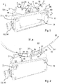
- Fig. 2 is the readhead off Fig. 1 in fully assembled condition, ie without the in Fig. 1 missing parts shown.
- the two sensor devices 3, 5 are mounted between two lateral plates 31, which serve together with an attractable screw 32 as a locking device 33, with which the angular positions of the two sensor devices 3, 5 are simultaneously fixed.
- the locking device 33 shown here is so one-handed operation.
- the two lateral plates 31 act as clamping elements 35, between which the sensor devices 3, 5 are arranged and with which the sensor devices 3, 5 can be clamped.
- the holes 39 that receive the axles 37 and thus serve as bearings for rotation about the rotation axis 30 are at the outer ends of the side plates 31 arranged.
- the side panels 31 protrude furthest from the housing 2 with respect to a height direction H.
- the side plates 31 have a concave shape in order to be able to absorb the wave as well as possible in the case of external scanning. Laterally outwardly, the plates 31 protrude less far from the housing 2 in order to allow an as close as possible placement of the scanning head 1 on the inner surface of the hollow shaft at a ggiabtastung a hollow shaft.
- the measurement in Fig. 1 takes place tangentially.
- the two sensor surfaces 4, 6 extend in a direction which runs tangentially to the direction of movement B of the rotation of a point on the outer surface of the shaft 13.
- the sensor surfaces 4, 6 extend in a direction which is parallel to the axial direction A of the shaft 13. In the different angular positions, the sensor surfaces have different sized intermediate angles. When measured on a shaft, the two sensor surfaces are therefore not aligned.
- Fig. 3 an adjustment of the sensor devices 3, 5 is shown with which an internal scanning of a hollow shaft is possible.
- the sensor surfaces 4, 6 point away from each other. Due to the convex configuration of the outer surface of the scanning head 1, it is possible to measure even on an inner surface of the hollow shaft. For this purpose, the sensor surfaces 4, 6 are pivoted to the rest of the scanning head 1 out.
- measurement as in the measurement in the Fig. 1 to a tangential measurement.
- the sensor devices 3, 5 and / or the clamping elements 35 can have roughenings, corrugations or coatings with a high coefficient of friction.
- the scanning head 1 is turned off Fig. 3 , apart from an electrical connection element 50, a twofold rotational symmetry.
- a rotation about an axis of symmetry S by 180 ° forms the scanning head 1 again on itself.
- the sensor devices 3, 5 are interchanged, ie they change their places.
- the axis of symmetry S thereby extends centrally through the scanning head 1 and through the attractable screw 32. It extends from one side, which faces the shaft, to a side which faces away from the shaft when the scanning head 1 is mounted on the shaft for measurement ,
- Such a symmetrical design results in that the scanning head can be mounted in two different orientations and the installer does not have to pay attention to the correct orientation during assembly.
- the evaluation software which evaluates the signals coming from the scanning head 1, be designed so that it tolerates different mounting orientations.
- a measured in an outer region 51 thickness D1 of the scanning head 1, which is measured in a width direction W is smaller than a measured in an inner region 52 thickness D2 of the scanning head 1.
- the outer region 51 lies on the side on which the Sensor devices 3, 5 are.
- a third sensor means may be provided which is immovable relative to the remainder of the scanning head. This could, for example, be located between the two sensor surfaces 4, 6.
- Fig. 5 is the narrower design at the outer region 51 in a plan view clearly visible.
- the top view shows the view along a height direction H, wherein the height direction H is perpendicular to the longitudinal direction L and perpendicular to the width direction W.
- the scanning head 1 has a smaller extension than in the longitudinal direction L and in the height direction H.
- Fig. 6 two scanning heads 1 are shown, wherein a scanning head 1 scans a measuring scale 16 outside and the other scanning head 1, the measuring scale 16 scans inside. This shows that the same scanning head 1 can be used for scanning both from the inside and from the outside by rotation of the sensor devices 3, 5.
- the scanning head 1 In addition to the twofold rotational symmetry about the axis S passing through the central screw along the height direction H, the scanning head 1, like the other scanning heads, has a mirror symmetry with respect to a plane parallel to that through the height directions H and the longitudinal direction L defined plane extends and passes through the center of the housing. It is thereby achieved that in a rotation about the longitudinal direction L, as for example in the two scanning heads in Fig. 6 has occurred, no offset of the sensor devices 3, 5 along the width direction W occurs.
- a further embodiment of a scanning head 1 is shown.
- the scanning head 1 shown is set for scanning an outer surface of a shaft.
- the scanning head 1 has a leaf spring 70. On the leaf spring 70, the two sensor devices 3, 5 are fixed.
- the leaf spring 70 is fastened to the housing 2 at its ends 71, 73. This attachment is variable. At each end, there are two elongated holes 74 in the leaf spring 70, so that the ends 71, 73 in the height direction H can be variably fixed to the housing 2.
- the fastening takes place here by means of screws 75, which pinch the leaf spring 70 between the screw head and the housing 2.
- screws 75 which pinch the leaf spring 70 between the screw head and the housing 2.
- the leaf spring 70 can attach to the housing 2 in the region of the center 72 of the leaf spring 70 in height direction H be variable.
- the same angular positions can be achieved if the attachment of the leaf spring 70 is changed at the ends 71, 73 and at the center 72 by the same amount in the height direction H.
- Each of the sensor devices 3, 5 is arranged between an end 71 or 73 and the center 72 of the leaf spring 70. As a result, each of the sensor devices 3, 5 can be adjusted independently of the other sensor device 5, 3. At the same time, each sensor device 3, 5 is placed at a fixed location, since the leaf spring has an elastic projection.
- the leaf spring 70 functions here as a carrier element for fastening the sensor device 3, 5.
- the in Fig. 7 Scanning head 1 shown is also applicable to an axial measurement.
- an axial measurement is measured not on an outer or inner surface of a shaft, but on an end face of the shaft.
- the two sensor surfaces 4, 6 scan a material measure, for example in the form of a code track, which is arranged on the end face (not shown).
- the two sensor surfaces 4, 6 point towards the end face. They extend along a radial direction of the shaft and in a direction tangential to the direction of movement of the rotation of a point on the end face of the shaft. They are therefore parallel to the end face of the shaft.
- the first sensor device scans a finely resolved material measure.
- the second sensor device scans the finely resolved material measure and a roughly resolved material measure. For this purpose, it is measured wider in the radial direction than the first sensor device. It may have one wide or two narrower sensor surfaces (not shown).
- Fig. 8 the scanning head 1 is off Fig. 7 shown in FIG Fig. 8 is set for measuring or scanning an inner surface of a hollow shaft.
- the ends 71, 73 of the leaf spring 70 are pushed along the height direction H to the housing as in Fig. 8 , so that the sensor devices 3, 5 bear against the housing 2 at their outer ends.
- the leaf spring 70 is spaced from the housing 2 of a spacer element 76. This spacing element may for example be made variable, so that attachment of the leaf spring 70 at variable distances from the housing 2 is possible.
- the thickness of the leaf spring 70 and thus its hardness should be chosen so that a deformation is still possible, however, an unnecessary vibration behavior of the spring and the sensor devices 3, 5 mounted thereon is largely suppressed.
- the sensor surfaces 4, 6 upstream of an end face 40 of the housing 2.
- the sensor devices 3, 5 are again located between the sensor surfaces 4, 6 and the end face 40.
- the sensor devices 3, 5 are again separate components and are located completely in front of the end face 40.
- the sensor devices 3, 5 from the FIGS. 7 and 8 are rotatable. Unlike the previous embodiments, however, the rotation axis is not fixed to an axis 7 or 37. Rather, the axis of rotation about which the sensor devices 3, 5 are rotated, moves during the movement.
- the leaf spring 70 can be fixed in different positions fixed to the housing 2.
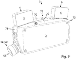
- a scanning head 1 can be seen, the scanning of the FIGS. 7 and 8 similar.
- a plug face 53 of a connection element 50 obliquely away from an end face 40 of the housing 2 away. This allows a more compact design than an embodiment in which the plug face 53 points in the longitudinal direction L, in which the end face 40 extends.
Landscapes
- Physics & Mathematics (AREA)
- General Physics & Mathematics (AREA)
- Length Measuring Devices With Unspecified Measuring Means (AREA)
Description
- Die Erfindung betrifft speziell einen Abtastkopf für einen Geber zur Erfassung von Rotations- bzw. Linearparametern, beispielsweise Position, Geschwindigkeit oder Beschleunigung, eines drehbaren oder linear bewegbaren Bauelementes, insbesondere einer Welle oder einer linearen Strecke.
- Um beispielsweise die Rotationsposition eines drehbaren Bauelementes festzustellen, wird in vielen Fällen eine Maßverkörperung an dem drehbaren Bauelement angebracht, die einer Sensorfläche einer Sensoreinrichtung gegenüberliegt und die von einer Sensorfläche abgetastet wird. Neuere Systeme, wie sie beispielsweise aus der
DE 10 2010 061 738.5 bekannt sind, benutzen dabei eine Maßverkörperung, die sich nicht über die kompletten 360° einer Umdrehung erstreckt und zwischen ihren Enden eine Lücke bildet. Um diese Lücke zu überbrücken, ist es notwendig, zwei oder mehr Sensorflächen, deren Abstand voneinander größer als die Lücke ist, zur Positionsermittlung zu benutzen. Auch bei anderen Messsystemen, beispielsweise bei solchen, die mit Nonius oder zusätzlichen Pseudo-Code-Spuren arbeiten, kann es notwendig sein, dass mindestens zwei in einer Umfangsrichtung des drehbaren Bauelements oder in der Verfahrrichtung eines linear bewegbaren Bauelements versetzt angeordnete Sensorflächen vorhanden sind. - Sehr große drehbare Bauelemente werden üblicherweise nur als Einzelstücke oder nur in kleinen Serien gefertigt. In solchen Fällen werden die Abtastköpfe für jeden Durchmesser des drehbaren Bauelements einzeln maßgefertigt. Dies stellt einen großen Aufwand dar.
- Aus der
EP 26 605 67 A1 ist ein Abtastkopf für einen Geber bekannt. Dieser umfasst ein Gehäuse und eine erste und eine zwei Sensorfläche. Die Sensorflächen sind verstellbar in dem Gehäuse angeordnet und befinden sich jeweils an einem Ende einer Sensoreinrichtung. Die Sensoreinrichtungen des Abtastkopfs befinden sich auf der Aussenseite des Sensorgehäuses
DieDE 10 2005 056 207 A1 zeigt ein Sensorsystem, welches aus einzelnen standardisierten Sensorelementen besteht. Die Sensorelemente können in Sensorgruppen zu zwei oder drei Sensorelemente zusammengefasst werden, indem diese durch eine flexibel ausgebildete Flexfolie miteinander verbunden sind. - Die Aufgabe der Erfindung ist es, einen Abtastkopf mit einem verringerten Herstellungsaufwand und einer einfachen Handhabung bereitzustellen, der zugleich weniger Platz für die Abtastung am bewegbaren Bauelement benötigt.
- Die Aufgabe wird dadurch gelöst, dass ein Abtastkopf nach Anspruch 1 bereitgestellt wird, der sich an Wellen oder andere drehbare Bauelemente mit verschieden großen Durchmessern und/oder an linear bewegbare Bauelemente mit geringem Aufwand und Platzbedarf anpassen lässt.
- Dazu umfasst der Abtastkopf ein Gehäuse mit einer Stirnseite, eine erste, am Gehäuse angeordnete Sensoreinrichtung mit einer ersten Sensorfläche, die zumindest teilweise in dieselbe Richtung weist wie die Stirnseite, und eine zweite, am Gehäuse versetzt angeordnete Sensoreinrichtung mit einer zweiten Sensorfläche, die ebenfalls zumindest teilweise in dieselbe Richtung weist wie die Stirnseite, wobei die erste und die zweite Sensoreinrichtung in mindestens zwei unterschiedlichen Winkelstellungen der Sensorflächen zueinander am Gehäuse anordenbar sind und die Sensorflächen der Stirnseite vorgelagert sind. Dadurch, dass die beiden Sensorflächen in verschiedenen Winkelstellungen zueinander am Gehäuse anordenbar sind, kann der Abtastkopf beispielsweise zur Abtastung von Wellen mit verschiedenen Durchmessern und/oder zur Abtastung eines linear beweglichen Bauelementes benutzt werden.
- Erfindungsgemäß wird diese Aufgabe gelöst, wenn sich die Sensoreinrichtungen zwischen den Sensorflächen und der Stirnseite befinden.
- Durch diese Ausgestaltung können die Sensoreinrichtungen schmaler als das Gehäuse ausgeführt sein, wobei sich gleichzeitig die Gesamtbreite des Abtastkopfes nicht vergrößert, so dass Längenänderungen des Bauelementes besser ausgeglichen werden können und dabei die Baugröße des Abtastkopfes nicht vergrößert wird.
- Die Sensoreinrichtungen sind separate Bauteile , die sich vollständig vor der Stirnseite befinden. Die Ausbildung als separate Bauteile, die außerhalb des Gehäuses liegen, und sich vollständig vor der Stirnseite befinden, erlaubt eine besonders kompakte Ausgestaltung, vor allem in der Breitenrichtung. Insbesondere kann sich eine Projektion der Sensorflächen auf die Stirnseite komplett innerhalb des Querschnittes der Stirnfläche befinden. Eine solche Projektion kann insbesondere parallel zu einer Normalenrichtung der Stirnseite und/oder den Normalenrichtungen der Sensorflächen erfolgen.
- Die erfindungsgemäße Lösung kann mit den folgenden, jeweils für sich vorteilhaften und beliebig miteinander kombinierbaren Weiterentwicklungen und vorteilhaften Ausgestaltungen weiter verbessert werden.
- Um die mindestens zwei unterschiedlichen Winkelstellungen der Sensorflächen zu ermöglichen, sind die Sensoreinrichtungen jeweils um eine Drehachse drehbar. In einer vorteilhaften Ausgestaltung befinden sich die Drehachsen der Sensoreinrichtungen näher an den die Sensorflächen bildenden Seiten der Sensoreinrichtungen als an den Seiten, die den die Sensorflächen bildenden Seiten gegenüberliegen. Die Drehachsen der Sensoreinrichtungen können sich an den die Sensorflächen bildenden Seiten der Sensoreinrichtungen befinden. Eine solche Ausgestaltung kann eine unabhängige Erfindung darstellen, bei der die Sensoreinrichtungen nicht notwendigerweise zwischen den Sensorflächen und der Stirnseite angeordnet sein müssen. Bei dieser Ausgestaltung bewegt sich die Sensorfläche bei einer Drehung weniger stark als bei einer Ausgestaltung, bei der die Drehachse weiter von der Sensorfläche entfernt ist. Dadurch können Bewegungen entlang einer Umfangsrichtung eines drehbaren Elementes bei Anpassung an verschiedene Durchmesser minimiert werden. Insbesondere kann die Drehachse durch die Sensorfläche verlaufen und/oder in einer Ebene, die zumindest durch Teile der Sensorfläche definiert sind, liegen. Vorzugsweise kann die Drehachse in einen mittleren Bereich einer Sensorfläche liegen.
- In einer weiteren vorteilhaften Ausgestaltung liegen die Drehachsen außerhalb des Gehäuses. Eine solche Ausgestaltung kann eine Bewegung der Sensorfläche in möglichst viele verschiedene Winkelstellungen ermöglichen, insbesondere auch in Winkelstellungen, die eine Innenabtastung einer Hohlwelle ermöglichen, also in eine Winkelstellung, in der die beiden Sensorflächen voneinander weg weisen.
- In einer besonders vorteilhaften Ausgestaltung liegen die Drehachsen an oder vor der Stirnseite des Gehäuses. In einer Projektion auf die Stirnseite, speziell entlang einer Normalenrichtung der Stirnseite, durchkreuzen die Drehachsen die Stirnseite.
- Zumindest eine der Sensoreinrichtungen kann im montierten Zustand auf einer geraden Verbindungslinie zwischen dem Gehäuse und einer Maßverkörperung des zu vermessenden Bauelementes liegen. Dadurch ist eine besonders kompakte Ausgestaltung ermöglicht.
- Es kann eine auf die beiden Sensoreinrichtungen gleichzeitig einwirkende Feststelleinrichtung vorhanden sein, durch die die Winkelstellungen der beiden Sensoreinrichtungen fixierbar sind. Im Vergleich zu mehreren Feststelleinrichtungen, die jeweils nur auf eine einzige Sensoreinrichtung einwirken, ist dadurch die Bedienbarkeit erleichtert. Insbesondere kann die Feststelleinrichtung so ausgestaltet sein, dass sie einhändig bedient werden kann. Beispielsweise kann eine Fixierung durch das Festziehen einer einzigen Schraube geschehen.
- Die Feststelleinrichtung kann wenigstens zwei Klemmelemente aufweisen, zwischen denen wenigstens eine der Sensoreinrichtungen angeordnet ist. Die Fixierung einer oder beider Sensoreinrichtungen kann durch Einklemmen zwischen den Klemmelementen erfolgen. Bei den Klemmelementen kann es sich beispielsweise um Klemmbacken und/oder um flächige Klemmelemente, beispielsweise um blechartige Klemmelemente handeln.
- Die Sensoreinrichtungen und/oder die Klemmelemente können Aufrauungen, Riffelungen und/oder Beschichtungen mit einem hohen Reibungskoeffizienten aufweisen, um die Klemmwirkung zu verstärken. Vorzugsweise sind beide Sensoreinrichtungen zwischen den wenigstens zwei Klemmelementen angeordnet.
- Der so ausgestaltete Abtastkopf ermöglicht also ohne Austausch von Teilen die Messung an mindestens zwei verschieden großen Durchmessern und/oder die Messung an einer linearen Strecke, indem die Winkelstellung der Sensorflächen je nach Bedarf eingestellt wird. Sind die Sensorflächen stärker zueinander geneigt, schließen sie einen kleineren Winkel zwischen sich ein und sind zur Messung an kleineren Durchmessern geeignet. Zur Messung an größeren Durchmessern ist der Winkel zwischen den beiden Sensorflächen größer. Soll eine lineare Strecke gemessen werden, sollten die Sensorflächen parallel und miteinander fluchtend ausgerichtet sein
- Die erste und die zweite Sensorfläche können in den mindestens zwei unterschiedlichen Winkelstellungen der Sensorflächen zueinander am Gehäuse anbringbar sein, insbesondere können sie am Gehäuse befestigbar sein. Vorteilhafterweise sind sie schon am Gehäuse angebracht oder befestigt.
- Der Abtastkopf kann eine Fixiereinrichtung aufweisen, die eine Fixierung von erster und zweiter Sensoreinrichtung in den mindestens zwei Winkelstellungen der Sensorflächen zueinander ermöglicht. Eine Änderung der Winkelstellung kann bei einer Fixiereinrichtung nur erfolgen, wenn die Fixiereinrichtung in einer Löseposition ist. Beispielsweise kann eine Schraube als Fixiereinrichtung dienen. Wenn die Schraube angezogen ist, kann die Sensoreinrichtung dadurch fixiert sein. Wenn die Schraube nicht angezogen ist, kann die Sensoreinrichtung bewegt werden.
- Die Sensorflächen können plan sein. Alternativ können sie auch gekrümmt sein. Beispielsweise können sie leicht konvex sein, um nicht nur Messungen an Außenflächen, sondern auch an konkaven Innenflächen zu erlauben.
- Die zwei Sensorflächen können in einer Ausgestaltung eine Normalenrichtung aufweisen, die senkrecht zur Rotationsachse des drehbaren Bauelementes beispielsweise der Welle verläuft. In dieser Ausgestaltung liegen die Sensorflächen bevorzugt radial beabstandet von und gegenüber einer Umfangsfläche der Welle bzw. einer Maßverkörperung eines linear bewegbaren Bauelements.
- In einer anderen Ausgestaltung erfolgt die Abtastung axial, also mit axial von einer Stirnfläche des drehbaren Bauelementes beispielsweise der Welle beabstandeten bzw. der Stirnfläche gegenüberliegenden Sensorflächen. Bei dieser Ausgestaltung verläuft die Normalenrichtung der Sensorfläche parallel zur Rotationsachse des Bauelements. Die Winkelstellungen der zwei Sensorflächen unterscheiden sich wie bei der ersten Ausgestaltung in der Komponente, die tangential zur Bewegung eines Punktes auf dem drehbaren Bauelement verläuft.
- In einer weiteren vorteilhaften Ausgestaltung ist die erste und/oder die zweite Sensorfläche schwenkbar am Gehäuse angeordnet, angebracht oder befestigt. Durch die schwenkbare Ausgestaltung kann die Ausrichtung der Sensorfläche in mehreren Stufen oder kontinuierlich an unterschiedliche Durchmesser des drehbaren Bauelements angepasst werden. Die Ausrichtung der Sensorflächen kann folglich so erfolgen, dass stets die maximale Sensorfläche von der vorbeibewegten Maßverkörperung erfasst wird bzw. der Luftspalt zwischen den jeweiligen Sensorflächen und der Maßverkörperung, die auf dem drehbaren Bauelement bzw. dem linearen Bauelement angebracht ist, optimal ist.
- Die Sensorfläche kann Teil einer Sensoreinrichtung sein, die zusätzlich zur Sensorfläche auch weitere Elemente, wie beispielsweise Schaltkreise zur Signalbearbeitung aufweisen kann. Die Sensoreinrichtung kann schwenkbar am Gehäuse angeordnet, angebracht oder befestigt sein.
- Die erste und/oder die zweite Sensorfläche können mittelbar oder unmittelbar schwenkbar am Gehäuse angeordnet, angebracht oder befestigt sein. Eine mittelbare Anordnung wäre beispielsweise eine Anordnung über ein zwischen dem Gehäuse und der Sensorfläche liegendes drittes Element.
- In einer weiteren vorteilhaften Ausgestaltung ist eine der beiden Sensorflächen, beispielsweise die erste Sensorfläche unbeweglich am Gehäuse befestigt und die andere Sensorfläche, in diesem Beispiel die zweite Sensorfläche, beweglich angeordnet, z.B. schwenkbar am Gehäuse befestigt. Diese Ausgestaltung ist im Vergleich zur Ausgestaltung mit zwei schwenkbaren oder zwei beweglichen Sensorflächen einfacher zu fertigen.
- Die Sensorflächen und/oder Sensoreinrichtung können unabhängig voneinander schwenkbar sein, so dass jede Sensorfläche für sich lageoptimiert werden kann.
- In einer weiteren Ausgestaltung sind die erste und die zweite Sensorfläche schwenkbar miteinander gekoppelt. Die Anpassung der Sensorflächen an verschiedene Durchmesser ist dabei besonders einfach, da nur die eine oder die andere Sensorfläche eingestellt werden muss und die andere Sensorfläche automatisch richtig mitjustiert wird. Eine solche Ausgestaltung erfordert jedoch einen verhältnismäßig hohen Aufwand.
- Der Abtastkopf kann, abgesehen von einem Anschlusselement, im Wesentlichen eine zweizählige Rotationssymmetrie aufweisen. Eine solche zweizählige Rotationssymmetrie, bei der bei einer Rotation des Abtastkopfes um 180° der Abtastkopf auf sich selbst abgebildet wird, hat den Vorteil, dass der Abtastkopf in zwei verschiedenen Rotationspositionen montiert werden kann. Beispielsweise muss der Monteur dadurch nicht mehr auf die richtige Ausrichtung des Abtastkopfes achten.
- Die Sensoreinrichtungen und/oder das Gehäuse und/oder die Klemmelemente können Ausrichthilfen in Form von außen einsehbaren Markierungen aufweisen, wobei jede Markierung einer vorbestimmten Winkelstellung der Sensoreinrichtungen zugeordnet ist. Eine solche Ausgestaltung kann es erlauben, den Abtastkopf schon vor der Montage auf eine bestimmte Winkelstellung, die etwa von einem Durchmesser eines abzutastenden Elementes abhängt, einzustellen. Die Einstellung kann etwa schon im Werk oder kurz vor der Montage erfolgen und muss nicht in den beengten Verhältnissen bei schon montiertem Abtastkopf erfolgen.
- Die Sensoreinrichtungen können an einer Blattfeder angeordnet sein, die an mindestens zwei Befestigungsstellen am Gehäuse befestigt ist. Durch die zwei Befestigungsstellen kann eine stabile Befestigung am Gehäuse ermöglicht sein. Aufgrund der elastischen Eigenschaften der Blattfeder liegen die Sensoreinrichtungen trotzdem an einem definierten Ort.
- Die Blattfeder kann an ihren Enden und an ihrer Mitte am Gehäuse befestigt sein, wobei je eine Sensoreinrichtung zwischen einem Ende und der Mitte angeordnet ist. Dies ermöglicht eine besonders stabile Ausgestaltung, bei der die beiden Sensoreinrichtungen voneinander unabhängig sind.
- Die Blattfeder kann in verschiedenen durchgebogenen Stellungen fixierbar am Gehäuse befestigt sein. Beispielsweise kann an einer oder an zwei Befestigungsstellen eine Verstellung der Sensoreinrichtung bezüglich eines Winkels oder bezüglich eines Abstandes vom Gehäuse ermöglicht sein. Dies kann etwa durch langlochförmige Ausnehmungen in der Blattfeder oder durch variable Befestigung an verschiedenen Stellen am Gehäuse ermöglicht sein.
- Die beiden Sensoreinrichtungen können bei gleicher Winkelstellung in mindestens zwei verschiedenen radialen Abständen vom Gehäuse angeordnet sein. Bei einer Ausgestaltung mit einer Blattfeder kann beispielsweise die Befestigung in der Mitte und an den Enden der Blattfeder so verstellbar sein, dass die Sensoreinrichtung bei gleicher Winkelstellung verschiedene Abstände vom Gehäuse aufweist. Dadurch ist beispielsweise eine Anpassung in einer radialen Richtung bei einem abzutastenden drehbaren Element möglich.
- Ein elektrisches Anschlusselement kann mit einem schräg von der Stirnseite weg weisenden Steckergesicht versehen sein. Ein solches Anschlusselement kann etwa schräg zu einer Mittelebene des Körpers verlaufen. Eine solche Ausgestaltung ist platzsparender als beispielsweise eine Ausgestaltung, bei der das Steckergesicht senkrecht zu der Stirnseite und/oder der Mittelebene verläuft.
- Wie eingangs beispielhaft beschrieben, ist bei einigen Messsystemen die Verwendung von zwei Sensoreinrichtungen notwendig, um eine Lücke zwischen zwei Abschnitten der Maßverkörperung zu überbrücken. In diesem Fall sollte der Abstand zwischen den beiden Sensoreinrichtungen größer als die Lücke sein, so dass im Bereich der Lücke stets zumindest eine Sensoreinrichtung noch die Maßverkörperung abtastet. Bei anderen Messsystemen werden beide Sensoreinrichtungen immer gleichzeitig benutzt und die Positionsinformation aus der Kombination der beiden Sensoren gewonnen. Bei solchen Systemen kann es notwendig sein, dass der Abstand der beiden Sensoreinrichtungen entlang der Maßverkörperung einen vorbestimmten Wert aufweist. Dies ist der Fall, wenn mit Hilfe der beiden Sensoreinrichtungen zwei Signale durch die Abtastung der einen Verkörperung erzeugt werden sollen, die um einen bestimmten Phasenwinkel zueinander versetzt sind. Da sich bei verschiedenen Winkelstellungen die Abstände zwischen den Sensoreinrichtungen unterscheiden können, ist es besonders vorteilhaft, wenn sich die Sensoreinrichtungen in unterschiedlichem Abstand voneinander anordnen, anbringen oder befestigen lassen. Dadurch kann der Abstand in den verschiedenen Winkelstellungen richtig eingestellt werden.
- Vorteilhafterweise ist nicht nur die Anordnung von erster und zweiter Sensorfläche in zwei unterschiedlichen Winkelstellungen, sondern in einer beliebigen Winkelstellung innerhalb eines kontinuierlichen Bereichs möglich. Dadurch kann der Abtastkopf nicht nur für zwei unterschiedliche Durchmesser, sondern für Durchmesser in einem kontinuierlichen Bereich verwendet werden.
- Bei den Sensoreinrichtungen kann es sich um kontaktlos messende Sensoreinrichtungen handeln. Als Messverfahren können beispielsweise induktive, kapazitive, magnetische und/oder optische Verfahren zum Einsatz kommen. Die kontaktlose Messung verursacht weniger Verschleiß als eine Messung mit einem direkten Kontakt. In einer besonders vorteilhaften Ausgestaltung sind die Sensoreinrichtungen magnetisch messende Sensoreinrichtungen.
- Neben der ersten und der zweiten Sensoreinrichtung kann noch eine dritte Sensoreinrichtung mit einer dritten Sensorfläche vorgesehen sein, um die Messung zu verbessern. Die dritte Sensorfläche muss dabei nicht bewegbar oder schwenkbar am Gehäuse angeordnet sein, was den Fertigungsaufwand verringert und den Justiervorgang beim Montieren des Abtastkopfes erleichtert. Die dritte Sensorfläche kann sich beispielsweise zwischen der ersten und der zweiten Sensorfläche befinden.
- Um nicht nur die Rotation von Wellen, sondern auch eine lineare Bewegung messen zu können, ist es vorteilhaft, wenn die Sensorflächen in eine erste Winkelstellung überführbar sind, in der sie miteinander fluchten. In der ersten Winkelstellung liegen die beiden Sensorflächen in einer Ebene und parallel zueinander, so dass eine gerade beziehungsweise plane Maßverkörperung, wie sie beispielsweise an einem linear bewegbaren Bauelement angebracht sein kann, abgetastet werden kann. Die Sensorflächen können ferner in eine zweite Winkelstellung überführbar sein, in der sie nicht miteinander fluchten, so dass die Messung an beispielsweise einer Welle oder einem anderen Rotationskörper möglich ist.
- Die zwei Sensoreinheiten können dieselbe Maßverkörperung abtasten. Dazu können die erste und die zweite Sensorfläche auf der gleichen, entlang einer Axialrichtung gemessenen Höhe liegen. Alternativ können die erste Sensorfläche und die zweite Sensorfläche verschiedene Maßverkörperungen abtasten, beispielsweise eine grob aufgelöste Maßverkörperung und eine fein aufgelöste Maßverkörperung.
- Der Abtastkopf kann eine Signalverarbeitungselektronik umfassen, die die Signale der Sensoreinrichtungen aufnimmt und zumindest teilweise weiterverarbeitet. Aufbereitete Informationen können dann mit einer einzigen Datenleitung weitergegeben werden.
- Im Folgenden ist die Erfindung anhand von Ausführungsbeispielen mit Bezug auf die Zeichnungen näher erläutert. Die bei den einzelnen Ausführungsbeispielen unterschiedlichen Merkmale können nach Maßgabe der obigen Ausführungen miteinander kombiniert werden. Außerdem können nach Maßgabe der obigen Darstellung auch einzelne Merkmale bei den Ausführungsbeispielen weggelassen werden, sollte es im speziellen Anwendungsfall auf den mit diesem Merkmal verbundenen Vorteil nicht ankommen.
- Es zeigen:
- Fig. 1
- eine schematische Perspektivansicht von Teilen eines erfindungsgemäßen Abtastkopfes;
- Fig. 2
- eine schematische Perspektivansicht des Abtastkopfes aus
Fig. 1 eingestellt auf eine Außenabtastung einer Welle; - Fig. 3
- eine schematische Perspektivansicht des Abtastkopfes aus
Fig. 2 , eingestellt auf eine Innenabtastung einer Hohlwelle; - Fig. 4
- eine schematische Perspektivansicht des Abtastkopfes aus den
Figuren 1 bis 3 ; - Fig. 5
- eine schematische Ansicht von oben auf den Abtastkopf aus den
Figuren 1 bis 4 ; - Fig. 6
- eine schematische Perspektivansicht zweier Abtastköpfe gemäß den
Figuren 1 bis 6 , die eine Maßverkörperung außen bzw. innen abtasten; - Fig. 7
- eine schematische Perspektivansicht einer weiteren Ausführungsform eines Abtastkopfes, eingestellt auf eine Außenabtastung einer Welle;
- Fig. 8
- eine schematische Perspektivansicht des Abtastkopfes aus
Fig. 7 , eingestellt auf eine Innenabtastung einer Hohlwelle; - Fig. 9
- eine schematische Perspektivansicht eines weiteren Abtastkopfes.
-
Fig. 1 zeigt eine schematische Ansicht eines Abtastkopfes 1 mit einem Gehäuse 2 sowie einer ersten, am Gehäuse 2 angeordneten Sensoreinrichtung 3 mit einer ersten Sensorfläche 4 und einer zweiten, am Gehäuse 2 angeordneten, in einer Umfangsrichtung U einer Welle oder eines anderen drehbaren Bauteils (nicht gezeigt) zur ersten Sensoreinrichtung 3 versetzt angeordneten Sensoreinrichtung 5 mit einer zweiten Sensorfläche 6. Die beiden Sensoreinrichtungen 4, 6 sind zur Außenabtastung einer Welle 13 eingestellt. Sie weisen aufeinander zu. - Die beiden Sensorflächen 4, 6 liegen zur Bestimmung der Winkelposition einer Maßverkörperung gegenüber und tasten diese ab. Eine Sensorfläche 4, 6 kann eine Vorzugsrichtung definieren, entlang der die Messung besonders effizient ist. Eine solche Vorzugsrichtung kann etwa senkrecht zur Ausdehnung der Sensorfläche 4, 6 sein. Die beiden Sensorflächen 4, 6 sind in Umfangsrichtung zueinander versetzt und so zueinander geneigt, dass die jeweilige Vorzugsrichtung auf die Rotationsachse des drehbaren Bauelement gerichtet ist. Um eine Messung an drehbaren Bauelementen mit verschiedenen Durchmessern und/oder an einem linear bewegbaren Bauelement zu ermöglichen, lassen sich die Sensorflächen 4, 6 in mindestens zwei Winkelstellungen zueinander anordnen.
- Die erste und die zweite Sensoreinrichtung 3, 5 sind jeweils über eine Achse 30 schwenkbar am Gehäuse 2 befestigt. Die optionalen schlitzförmigen Ausnehmungen 8 an den Sensoreinrichtungen 3, 5 ermöglichen dabei, dass die Sensoreinrichtungen 3, 5 innerhalb eines kontinuierlichen Bereichs geführt schwenkbar sind. Jede der beiden Sensoreinrichtungen 3, 5 verfügt über eine Fixiereinrichtung 9 beispielsweise in Form einer Schraube, die durch die schlitzförmige Ausnehmung 8 ragt und die Sensoreinrichtung 3 beziehungsweise 5 fixiert. Der hier gezeigte Abtastkopf 1 ermöglicht also eine Fixierung von erster und zweiter Sensorfläche 4, 6 unabhängig voneinander in einer beliebigen Winkelstellung zueinander innerhalb eines kontinuierlichen Bereichs. Der so ausgestaltete Abtastkopf 1 kann an verschiedene Wellendurchmesser angepasst werden. Alternativ zur dargestellten Ausgestaltung könnten schlitzförmige Ausnehmungen am Gehäuse 2 vorhanden sein, um eine Verschwenkung zu ermöglichen.
- Die beiden Sensoreinrichtungen 3, 5 verfügen neben den Sensorflächen 4, 6 noch jeweils über eine Sensorelektronik (nicht gezeigt) im Inneren der Sensoreinrichtung 3, 5. Die Sensoreinrichtungen 3, 5 sind mit Verbindungselementen mit einer Signalverarbeitungselektronik (nicht gezeigt) in einem Hohlraum 11 des Abtastkopfes 1 verbunden. Diese Signalverarbeitungselektronik kann beispielsweise dazu dienen, die Sensorsignale weiter zu verarbeiten und schon ein fertiges Positionssignal, und/oder Geschwindigkeitssignale und/oder Beschleunigungssignal auszugeben, das über den Ausgang 12 ausgegeben wird.
- In
Fig. 2 ist ein Abtastkopf 1 zusammen mit einem Spannband 14 gezeigt. Das Spannband 14 wird mittels eines Spannschlosses (nicht gezeigt) auf eine Welle 13 gespannt, wodurch es fest am Umfang der Welle 13 anliegt. Außerhalb des Bereichs des Spannschlosses verfügt das Spannband 14 über eine Maßverkörperung 16. In diesem Fall handelt es sich um eine magnetische Maßverkörperung 16, die von den magnetisch messenden Sensoreinrichtungen 3, 5 erfasst wird. Um die durch das Spannschloss verursachte, zum Spannen notwendige Lücke zwischen den Bereichen mit der Maßverkörperung zu überbrücken, verfügt der Abtastkopf 1 über zwei Sensoreinrichtungen 3, 5, sodass immer mindestens eine Sensoreinrichtung 3, 5 die Maßverkörperung 16 erfassen und messen kann. - Die zur Welle 13 hin zeigenden Außenflächen der Sensoreinrichtungen 3, 5 und die zur Welle 13 hin zeigende Außenfläche des Abtastkopfes 1 sind leicht konvex ausgestaltet, so dass eine Anbringung an verschieden großen Wellen möglich ist. Durch die konvexe Ausgestaltung ist es zusätzlich möglich, die Sensorflächen 4, 6 so anzuordnen, dass sie miteinander fluchten, wodurch nicht nur die Rotationsbewegung einer Welle, sondern auch eine lineare Bewegung einer ebenen Fläche erfasst werden kann. Sogar die Anbringung im Inneren einer großen Hohlwelle ist durch diese Ausgestaltung möglich.
- Zur Befestigung und zur Justierung des Abtastkopfes 1 verfügt dieser über zwei Langlöcher 21, in die Befestigungselemente, beispielsweise Schrauben, einführbar sind.
- Bei manchen Messmethoden kann es notwendig sein, dass zwischen der ersten Sensorfläche 4 und der zweiten Sensorfläche 6 ein bestimmter Abstand entlang der Umfangsrichtung U besteht. In einer vorteilhaften Ausgestaltung lässt sich daher der Abstand der beiden Sensorflächen 4, 6 verstellen, beispielsweise indem die Sensoreinheiten in unterschiedlichem Abstand voneinander anordenbar, anbringbar oder befestigbar ausgestaltet sind.
- Die in den
Fig. 1 bis 4 gezeigten Sensoreinrichtungen 3, 5 sind unabhängig voneinander schwenkbar. Dadurch ist es möglich, dass der Abtastkopf 1 relativ zur Welle 13 in einem vergleichsweise breiten Bereich anordenbar ist. In derFig. 2 könnte der Abtastkopf 1 auch weiter links oder weiter rechts angeordnet sein. Um diesen Versatz auszugleichen, müsste eine der beiden Sensoreinrichtungen 3 oder 5 und damit die eine Sensorfläche 4 oder 6 weiter nach innen und die andere Sensoreinheit 5 bzw. 3 mit der anderen Sensorfläche 6 bzw. 4 weiter nach außen verschwenkt werden. - Alternativ könnten die beiden Sensoreinrichtungen 3, 5 und damit die beiden Sensorflächen 4, 6 schwenkbar miteinander gekoppelt sein, beispielsweise über ein Getriebe (nicht gezeigt) oder über Einzelantriebe. Eine solche Ausgestaltung würde die Anpassung an den Wellendurchmesser vereinfachen, da nur eine Sensoreinrichtung 3 oder 5 justiert werden müsste und die andere Sensoreinrichtung 5 bzw. 3 automatisch richtig mitjustiert werden würde. Allerdings wäre es dazu notwendig, dass die Relativposition zwischen dem Abtastkopf 1 und der Welle 13 vergleichsweise genau festgelegt ist.
- Bei dem in
Fig. 1 dargestellten Abtastkopf 1 mit einem Gehäuse 2 sind Teile zur besseren Sichtbarkeit der Funktionsweise entfernt dargestellt. Die erste Sensorfläche 4 und die zweite Sensorfläche 6 weisen zumindest teilweise in dieselbe Richtung wie eine Stirnfläche 40 des Gehäuses 2, d.h. die Normalenrichtungen der Sensorflächen 4 und 6 weisen Komponenten auf, die parallel zur Oberflächennormale der Stirnseite 40 sind. Die beiden Sensorflächen 4, 6 und die Stirnseite 40 weisen jeweils vom Gehäuse 2 aus nach außen. Die Sensorflächen 4, 6 sind der Stirnseite 40 dabei vorgelagert. Sie befinden sich weiter außen als die Stirnseite 40. Die Sensoreinrichtungen 3, 5 befinden sich zwischen den Sensorflächen 4, 6 und der Stirnseite 40. Dadurch ist eine schmale Ausgestaltung im Bereich der Sensorflächen 4, 6 möglich, da die Sensoreinrichtungen 3, 5 außerhalb des Gehäuses 2 liegen und dadurch die Breite des Abtastkopfes 1, gemessen entlang einer Breitenrichtung W im Bereich der Sensorflächen 4, 6 kleiner sein kann als im Bereich des Gehäuses 2. Dies erlaubt eine größere Toleranz im vorderen/äußeren Bereich 51. Beispielsweise können dadurch Bewegungen oder Lage-/Längenänderungen des zu messenden Bauelementes, die beispielsweise aufgrund von temperaturabhängigen Ausdehnungen entstehen, besser toleriert werden. - Die Sensoreinrichtungen 3, 5 sind jeweils um Drehachsen 30 drehbar, die durch Achsen 37 verlaufen. Die Achsen 37 werden von Vorsprüngen 38 an den Sensoreinrichtungen 3, 5 gebildet, die in Löchern 39 an den seitlichen Blechen 31 angeordnet sind (siehe
Fig. 2 ). Die Drehachsen 30 befinden sich an den die Sensorflächen 4, 6 bildenden Seiten 34, 36 der Sensoreinrichtungen 3, 5. Die Drehachsen 30 befinden sich also näher an den die Sensorflächen 4, 6 bildenden Seiten 34, 36 der Sensoreinrichtungen 3, 5 als an den Sensorflächen 4, 6 gegenüberliegenden Seiten 44, 46. Insbesondere befinden sie sich mittig bezüglich der Sensorflächen 4, 6. Aufgrund dieser Ausgestaltung ist eine Änderung des Abstandes der Sensorflächen 4, 6 zueinander bei einer Veränderung der Winkelstellung zueinander minimiert. - Auch die Tatsache, dass die Drehachsen 30 außerhalb des Gehäuses, insbesondere vor der Stirnseite 40 des Gehäuses 2 liegen, trägt dazu bei, dass die Anpassung an verschiedene Wellendurchmesser besonders einfach ist.
- Die Sensoreinrichtungen 3, 5 sind jeweils als separate Bauelemente ausgebildet und befinden sich vollständig vor der Stirnseite 40 des Gehäuses 2.
- In
Fig. 2 ist der Abtastkopf ausFig. 1 im vollständig montierten Zustand, d.h. ohne die inFig. 1 fehlenden Teile dargestellt. - Die beiden Sensoreinrichtungen 3, 5 sind zwischen zwei seitlichen Blechen 31 angebracht, die zusammen mit einer anziehbaren Schraube 32 als Feststelleinrichtung 33 dienen, mit der die Winkelstellungen der beiden Sensoreinrichtungen 3, 5 gleichzeitig fixierbar sind. Die hier gezeigte Feststelleinrichtung 33 ist also einhändig bedienbar. Die beiden seitlichen Bleche 31 wirken als Klemmelemente 35, zwischen denen die Sensoreinrichtungen 3, 5 angeordnet sind und mit dem die Sensoreinrichtungen 3, 5 geklemmt werden können.
- Die Löcher 39, die die Achsen 37 aufnehmen und damit als Lager für eine Drehung um die Drehachse 30 dienen, sind an den äußeren Enden der seitlichen Bleche 31 angeordnet. In diesem Bereich ragen die seitlichen Bleche 31 bezüglich einer Höhenrichtung H am weitesten vom Gehäuse 2 hervor. Zwischen den Löchern 39 weisen die seitlichen Bleche 31 eine konkave Form auf, um bei einer Außenabtastung die Welle möglichst gut aufnehmen zu können. Seitlich nach außen hin ragen die Bleche 31 weniger weit vom Gehäuse 2 ab, um bei einer Innenabtastung einer Hohlwelle eine möglichst nahe Platzierung des Abtastkopfes 1 an der inneren Oberfläche der Hohlwelle zu ermöglichen.
- Die Messung in
Fig. 1 erfolgt tangential. Die beiden Sensorflächen 4, 6 erstrecken sich in einer Richtung, die tangential zur Bewegungsrichtung B der Rotation eines Punktes auf der Außenfläche der Welle 13 verläuft. Zusätzlich erstrecken sich die Sensorflächen 4, 6 in einer Richtung, die parallel zur Axialrichtung A der Welle 13 verläuft. In den verschiedenen Winkelstellungen weisen die Sensorflächen verschieden große Zwischenwinkel auf. Bei Messung an einer Welle fluchten die beiden Sensorflächen also nicht. - In
Fig. 3 ist eine Einstellung der Sensoreinrichtungen 3, 5 dargestellt, mit der eine Innenabtastung einer Hohlwelle möglich ist. Die Sensorflächen 4, 6 weisen dabei voneinander weg. Durch die konvexe Ausgestaltung der Außenfläche des Abtastkopfes 1 ist es möglich, auch an einer Innenfläche der Hohlwelle zu messen. Dazu werden die Sensorflächen 4, 6 zum Rest des Abtastkopfes 1 hin verschwenkt. Bei der inFig. 3 dargestellten Messung handelt es sich, wie bei der Messung in denFig. 1 , um eine tangentiale Messung. - Um einen möglichst sicheren Halt der Sensoreinrichtungen 3, 5 zu gewährleisten, können die Sensoreinrichtungen 3, 5 und/oder die Klemmelemente 35 Aufrauungen, Riffelungen oder Beschichtungen mit einem hohen Reibungskoeffizienten aufweisen.
- Wie auch die anderen Abtastköpfe 1, weist der Abtastkopf 1 aus
Fig. 3 , abgesehen von einem elektrischen Anschlusselement 50, eine zweizählige Rotationssymmetrie auf. Eine Rotation um eine Symmetrieachse S um 180° bildet den Abtastkopf 1 wieder auf sich selbst ab. Die Sensoreinrichtungen 3, 5 werden dabei vertauscht, d.h. sie wechseln ihre Plätze. Die Symmetrieachse S verläuft dabei mittig durch den Abtastkopf 1 und durch die anziehbare Schraube 32. Sie verläuft von einer Seite, die der Welle zugewandt ist, zu einer Seite, die der Welle abgewandt ist, wenn der Abtastkopf 1 zur Messung an der Welle angebracht ist. Eine solche symmetrische Ausgestaltung führt dazu, dass der Abtastkopf in zwei verschiedenen Orientierungen montiert werden kann und der Monteur bei der Montage nicht mehr auf die korrekte Orientierung achten muss. Nichtsdestotrotz muss natürlich die Auswertesoftware, die die vom Abtastkopf 1 kommenden Signale auswertet, so ausgestaltet sein, dass sie verschiedene Montageorientierungen toleriert. - Eine in einem äußeren Bereich 51 gemessene Dicke D1 des Abtastkopfes 1, die in einer Breitenrichtung W gemessen wird, ist kleiner als eine in einem inneren Bereich 52 gemessene Dicke D2 des Abtastkopfes 1. Der äußeren Bereich 51 liegt dabei auf der Seite, auf der die Sensoreinrichtungen 3, 5 liegen.
- Zusätzlich zu den in den Figuren gezeigten zwei Sensoreinrichtungen 3, 5 können noch weitere Sensoreinrichtungen vorhanden sein. Beispielsweise kann eine dritte Sensoreinrichtung vorhanden sein, die relativ zum Rest des Abtastkopfes unbeweglich ist. Diese könnte sich beispielsweise zwischen den beiden Sensorflächen 4, 6 befinden.
- In
Fig. 5 ist die schmalere Ausgestaltung am äußeren Bereich 51 in einer Draufsicht gut zu erkennen. Die Draufsicht zeigt dabei die Ansicht entlang einer Höhenrichtung H, wobei die Höhenrichtung H senkrecht zur Längsrichtung L und senkrecht zur Breitenrichtung W verläuft. In der Breitenrichtung W hat der Abtastkopf 1 eine geringere Ausdehnung als in der Längsrichtung L und als in der Höhenrichtung H. - Zu erkennen ist in
Fig. 5 auch, dass sich der Abstand der Mittenbereiche 60, 61 der Sensorflächen 4, 6 bei einer Drehung der Sensoreinrichtungen 3, 5 um die Drehachsen 30 kaum verändert. - In
Fig. 6 sind zwei Abtastköpfe 1 gezeigt, wobei ein Abtastkopf 1 eine Maßverkörperung 16 außen abtastet und der andere Abtastkopf 1 die Maßverkörperung 16 innen abtastet. Dies zeigt, dass der gleiche Abtastkopf 1 durch Rotation der Sensoreinrichtungen 3, 5 zur Abtastung sowohl von innen, als auch von außen nutzbar ist. - Zusätzlich zu der zweizähligen Rotationssymmetrie um die Achse S, die durch die in der Mitte angeordnete Schraube entlang der Höhenrichtung H verläuft, weist der Abtastkopf 1, wie auch die anderen Abtastköpfe, eine Spiegelsymmetrie bezüglich einer Ebene, die parallel zu der durch die Höhenrichtung H und die Längsrichtung L definierte Ebene verläuft und mittig durch das Gehäuse geht. Dadurch wird erreicht, dass bei einer Rotation um die Längsrichtung L, wie sie beispielsweise bei den zwei Abtastköpfen in
Fig. 6 stattgefunden hat, kein Versatz der Sensoreinrichtungen 3, 5 entlang der Breitenrichtung W auftritt. - In
Fig. 7 ist eine weitere Ausgestaltung eines Abtastkopfes 1 gezeigt. Der gezeigte Abtastkopf 1 ist zur Abtastung einer Außenfläche einer Welle eingestellt. - Der Abtastkopf 1 weist eine Blattfeder 70 auf. Auf der Blattfeder 70 sind die beiden Sensoreinrichtungen 3, 5 befestigt. Die Blattfeder 70 ist an ihren Enden 71, 73 am Gehäuse 2 befestigt. Diese Befestigung ist dabei variabel. An jedem Ende sind zwei Langlöcher 74 in der Blattfeder 70 vorhanden, so dass die Enden 71, 73 in der Höhenrichtung H variabel am Gehäuse 2 befestigt werden können. Die Befestigung erfolgt hierbei über Schrauben 75, die die Blattfeder 70 zwischen dem Schraubenkopf und dem Gehäuse 2 einklemmen. Dadurch erfolgt eine Einstellung der Winkelstellung der Sensorflächen 4, 6 zueinander. Gleichzeitig verändert sich dabei der Abstand der Sensoreinrichtungen 3, 5 vom Gehäuse 2 in der Höhenrichtung H. Um die gleiche Winkelstellung der beiden Sensorflächen 4, 6 zueinander bei verschiedenen Höhen der Sensoreinrichtungen 3, 5 zu ermöglichen, kann dabei die Befestigung der Blattfeder 70 am Gehäuse 2 im Bereich der Mitte 72 der Blattfeder 70 in Höhenrichtung H variabel sein. Beispielsweise können gleiche Winkelstellungen erreicht werden, wenn die Befestigung der Blattfeder 70 an den Enden 71, 73 und an der Mitte 72 um jeweils den gleichen Betrag in der Höhenrichtung H verändert wird.
- Jede der Sensoreinrichtungen 3, 5 ist zwischen einem Ende 71 bzw. 73 und der Mitte 72 der Blattfeder 70 angeordnet. Dadurch lässt sich jede der Sensoreinrichtungen 3, 5 unabhängig von der anderen Sensoreinrichtung 5, 3 justieren. Gleichzeitig ist jede Sensoreinrichtung 3, 5 an einem festgelegten Ort platziert, da die Blattfeder einen elastischen Vorsprung aufweist. Die Blattfeder 70 fungiert hier als Trägerelement zur Befestigung der Sensoreinrichtung 3, 5.
- Der in
Fig. 7 gezeigte Abtastkopf 1 ist auch für eine axiale Messung anwendbar. Bei einer axialen Messung wird nicht an einer Außen- oder Innenfläche einer Welle, sondern an einer Stirnfläche der Welle gemessen. Die beiden Sensorflächen 4, 6 tasten eine Maßverkörperung beispielsweise in Form einer Codespur ab, die auf der Stirnfläche angeordnet ist (nicht gezeigt). Die beiden Sensorflächen 4, 6 zeigen zu der Stirnfläche hin. Sie erstrecken sich entlang einer Radialrichtung der Welle und in einer Richtung, die tangential zur Bewegungsrichtung der Rotation eines Punktes auf der Stirnfläche der Welle verläuft. Sie liegen also parallel zu der Stirnfläche der Welle. - In einer weiteren Variante der axialen Messung tastet die erste Sensoreinrichtung eine fein aufgelöste Maßverkörperung ab. Die zweite Sensoreinrichtung tastet die fein aufgelöste Maßverkörperung und eine grob aufgelöste Maßverkörperung ab. Dazu ist sie in der Radialrichtung gemessen breiter als die erste Sensoreinrichtung. Sie kann eine breite oder zwei schmalere Sensorflächen aufweisen (nicht gezeigt).
- In
Fig. 8 ist der Abtastkopf 1 ausFig. 7 dargestellt, wobei er inFig. 8 zur Messung bzw. Abtastung einer Innenfläche einer Hohlwelle eingestellt ist. Die Enden 71, 73 der Blattfeder 70 sind entlang der Höhenrichtung H weiter zum Gehäuse geschoben als inFig. 8 , so dass die Sensoreinrichtungen 3, 5 an deren äußeren Enden am Gehäuse 2 anliegen. Im mittleren Bereich 72 ist die Blattfeder 70 vom Gehäuse 2 des eines Beabstandungselementes 76 beabstandet. Dieses Beabstandungselement kann beispielsweise variabel ausgestaltet sein, so dass eine Befestigung der Blattfeder 70 in variablen Abständen vom Gehäuse 2 möglich ist. - Die Dicke der Blattfeder 70 und damit ihre Härte sollte so gewählt werden, dass eine Verformung noch möglich ist, ein unnötiges Schwingverhalten der Feder und der darauf angebrachten Sensoreinrichtungen 3, 5 jedoch weitgehend unterdrückt ist.
- Auch bei dem Abtastkopf 1 aus den
Figuren 7 und 8 sind die Sensorflächen 4, 6 einer Stirnseite 40 des Gehäuses 2 vorgelagert. Die Sensoreinrichtungen 3, 5 befinden sich wieder zwischen den Sensorflächen 4, 6 und der Stirnseite 40. Die Sensoreinrichtungen 3, 5 sind wieder separate Bauteile und befinden sich vollständig vor der Stirnseite 40. - Auch die Sensoreinrichtungen 3, 5 aus den
Figuren 7 und 8 sind drehbar. Anders als bei den vorherigen Ausgestaltungen ist die Drehachse jedoch nicht an einer Achse 7 oder 37 fixiert. Vielmehr bewegt sich die Drehachse, um die die Sensoreinrichtungen 3, 5 rotiert werden, während der Bewegung. - Wie in den
Figuren 7 und 8 gezeigt, kann die Blattfeder 70 in verschiedenen Stellungen fixierbar am Gehäuse 2 befestigt sein. - In
Fig. 9 ist ein Abtastkopf 1 zu sehen, der den Abtastkopf aus denFiguren 7 und 8 ähnelt. Im Gegensatz zu dem Abtastkopf aus denFiguren 7 und 8 weist ein Steckergesicht 53 eines Anschlusselementes 50 dabei jedoch schräg von einer Stirnseite 40 des Gehäuses 2 weg. Dies ermöglicht eine kompaktere Ausgestaltung als eine Ausführungsform, bei der das Steckergesicht 53 in die Längsrichtung L weist, in der auch die Stirnseite 40 verläuft.
Claims (15)
- Abtastkopf (1) für einen Geber zur Erfassung von Lage- und/oder Bewegungsparametern, wie zum Beispiel Position, Geschwindigkeit und Beschleunigung, umfassend ein Gehäuse (2) mit einer Stirnseite (40), eine erste, am Gehäuse (2) angeordnete Sensoreinrichtung (3) mit einer ersten Sensorfläche (4), die zumindest teilweise in dieselbe Richtung weist wie die Stirnseite (40), und eine zweite, am Gehäuse (2) versetzt angeordnete Sensoreinrichtung (5) mit einer zweiten Sensorfläche (6), die ebenfalls zumindest teilweise in dieselbe Richtung weist wie die Stirnseite (40), wobei die erste und die zweite Sensoreinrichtung (3, 5) in mindestens zwei unterschiedlichen Winkelstellungen der Sensorflächen (4, 6) zueinander am Gehäuse (2) anordenbar sind und die Sensorflächen (4, 6) der Stirnseite (40) vorgelagert sind, wobei sich die Sensoreinrichtungen (3, 5) zwischen den Sensorflächen (4, 6) und der Stirnseite (40) befinden, wobei die Sensoreinrichtungen (3, 5) separate Bauteile sind und sich vollständig vor der Stirnseite (40) befinden und wenigstens eine Sensoreinrichtung (3,5) drehbar am Gehäuse (2) angeordnet, angebracht oder befestigt ist um die zwei unterschiedlichen Winkelstellungen der Sensorflächen (4, 6) zu ermöglichten.
- Abtastkopf (1) nach Anspruch 1, dadurch gekennzeichnet, dass die wenigstens eine Sensoreinrichtung (3,5) schwenkbar am Gehäuse (2) angeordnet, angebracht oder befestigt ist.
- Abtastkopf (1) nach einem der vorhergehenden Ansprüche, dadurch gekennzeichnet, dass die Sensoreinrichtungen (3, 5) jeweils um eine Drehachse (30) drehbar sind und sich die Drehachsen (30) der Sensoreinrichtungen (3, 5) an den die Sensorflächen (4, 6) bildenden Seiten (34, 36) der Sensoreinrichtungen (3, 5) befinden.
- Abtastkopf (1) nach einem der vorhergehenden Ansprüche, dadurch gekennzeichnet, dass die Sensoreinrichtungen (3, 5) jeweils um eine Drehachse (30) drehbar sind und die Drehachsen (30) außerhalb des Gehäuses (2) liegen.
- Abtastkopf (1) nach einem der vorhergehenden Ansprüche, dadurch gekennzeichnet, dass die Sensoreinrichtungen (3, 5) jeweils um eine Drehachse (30) drehbar sind und die Drehachsen (30) an oder vor der Stirnseite (40) des Gehäuses (2) liegen.
- Abtastkopf (1) nach einem der vorhergehenden Ansprüche, dadurch gekennzeichnet, dass eine auf die beiden Sensoreinrichtungen (3, 5) gleichzeitig einwirkende Feststelleinrichtung (33) vorhanden ist, durch die die Winkelstellungen der beiden Sensoreinrichtungen (3, 5) fixierbar sind.
- Abtastkopf (1) nach Anspruch 6, dadurch gekennzeichnet, dass die Feststelleinrichtung (33) wenigstens zwei Klemmelemente (35) aufweist, zwischen denen wenigstens eine der Sensoreinrichtungen (3, 5) angeordnet ist.
- Abtastkopf (1) nach einem der vorhergehenden Ansprüche, dadurch gekennzeichnet, dass jeweils eine schlitzförmige Ausnehmung (8) an den Sensoreinrichtungen (3, 5) vorgesehen ist, so dass die Sensoreinrichtungen (3, 5) innerhalb eines kontinuierlichen Bereichs schwenkbar sind.
- Abtastkopf (1) nach einem der vorhergehenden Ansprüche, dadurch gekennzeichnet, dass der Abtastkopf (1), abgesehen von einem Anschlusselement (50), im Wesentlichen eine zweizählige Rotationssymmetrie aufweist.
- Abtastkopf (1) nach nach einem der vorhergehenden Ansprüche, dadurch gekennzeichnet, dass die Sensoreinrichtungen (3, 5) und/oder das Gehäuse (2) und/oder die Klemmelemente (35) Ausrichthilfen in Form von außen einsehbaren Markierungen aufweisen, wobei jeder Markierung eine vorbestimmte Winkelstellung der Sensoreinrichtungen (3, 5) zugeordnet ist.
- Abtastkopf (1) nach einem der vorhergehenden Ansprüche, dadurch gekennzeichnet, dass die Sensoreinrichtungen (3, 5) an einer Blattfeder (70) angeordnet sind, die an mindestens zwei Befestigungsstellen am Gehäuse (2) befestigt sind.
- Abtastkopf (1) nach Anspruch 11, dadurch gekennzeichnet, dass die Blattfeder (70) an ihren Enden (71, 73) und an ihrer Mitte (72) am Gehäuse (2) befestigt ist und je eine Sensoreinrichtung (3, 5) zwischen einem Ende (71, 73) und der Mitte (72) angeordnet ist.
- Abtastkopf (1) nach einem der Ansprüche 11 oder 12, dadurch gekennzeichnet, dass die Blattfeder (70) in verschieden durchgebogenen Stellungen fixierbar am Gehäuse (2) befestigt ist.
- Abtastkopf (1) nach einem der vorhergehenden Ansprüche, dadurch gekennzeichnet, dass ein elektrisches Anschlusselement (50) mit einem schräg von der Stirnseite (40) wegweisenden Steckergesicht (53) versehen ist.
- Abtastkopf (1) nach einem der vorhergehenden Ansprüche, dadurch gekennzeichnet, dass die Sensorflächen (4, 6) der Stirnfläche des drehbaren Bauelementes (13) gegenüberliegend angeordnet sind und von den Sensorflächen (4, 6) eine an der Stirnfläche vorgesehene Massverkörperung (16) erfassbar ist.
Priority Applications (1)
| Application Number | Priority Date | Filing Date | Title |
|---|---|---|---|
| EP14167295.6A EP2801796B1 (de) | 2013-05-07 | 2014-05-07 | Abtastkopf für einen Geber |
Applications Claiming Priority (2)
| Application Number | Priority Date | Filing Date | Title |
|---|---|---|---|
| EP13166894.9A EP2801795A1 (de) | 2013-05-07 | 2013-05-07 | Abtastkopf für einen Geber |
| EP14167295.6A EP2801796B1 (de) | 2013-05-07 | 2014-05-07 | Abtastkopf für einen Geber |
Publications (2)
| Publication Number | Publication Date |
|---|---|
| EP2801796A1 EP2801796A1 (de) | 2014-11-12 |
| EP2801796B1 true EP2801796B1 (de) | 2017-10-25 |
Family
ID=48236777
Family Applications (3)
| Application Number | Title | Priority Date | Filing Date |
|---|---|---|---|
| EP13166894.9A Ceased EP2801795A1 (de) | 2013-05-07 | 2013-05-07 | Abtastkopf für einen Geber |
| EP14167295.6A Active EP2801796B1 (de) | 2013-05-07 | 2014-05-07 | Abtastkopf für einen Geber |
| EP14723410.8A Active EP2994723B1 (de) | 2013-05-07 | 2014-05-07 | Abtastkopf für einen geber |
Family Applications Before (1)
| Application Number | Title | Priority Date | Filing Date |
|---|---|---|---|
| EP13166894.9A Ceased EP2801795A1 (de) | 2013-05-07 | 2013-05-07 | Abtastkopf für einen Geber |
Family Applications After (1)
| Application Number | Title | Priority Date | Filing Date |
|---|---|---|---|
| EP14723410.8A Active EP2994723B1 (de) | 2013-05-07 | 2014-05-07 | Abtastkopf für einen geber |
Country Status (4)
| Country | Link |
|---|---|
| US (1) | US10066963B2 (de) |
| EP (3) | EP2801795A1 (de) |
| DE (2) | DE102014006456B4 (de) |
| WO (1) | WO2014180879A1 (de) |
Families Citing this family (2)
| Publication number | Priority date | Publication date | Assignee | Title |
|---|---|---|---|---|
| EP3153821A1 (de) * | 2015-10-09 | 2017-04-12 | Siko GmbH | Sensoranordnung |
| CN117010420A (zh) * | 2018-06-08 | 2023-11-07 | 深圳盈达信息科技有限公司 | 扫描头能转动的pda |
Family Cites Families (16)
| Publication number | Priority date | Publication date | Assignee | Title |
|---|---|---|---|---|
| US3674934A (en) * | 1970-02-24 | 1972-07-04 | Us Navy | Minimum shift keyed (msk) phase measurement device |
| GB1444851A (en) * | 1973-08-07 | 1976-08-04 | Oelsch Fernsteuergeraete | Photoelectric sensor head |
| US4289983A (en) * | 1979-06-29 | 1981-09-15 | International Business Machines Corporation | Encoder for monitoring bidirectional motion |
| US4414675A (en) * | 1981-08-05 | 1983-11-08 | Motorola, Inc. | MSK and OK-QPSK signal demodulator |
| US4669095A (en) * | 1985-09-27 | 1987-05-26 | Motorola, Inc. | Maximum distance from zero crossing MSK demodulator |
| JP3321224B2 (ja) * | 1992-03-13 | 2002-09-03 | ティーディーケイ株式会社 | 移動物体検出装置 |
| JP3114553B2 (ja) * | 1995-02-17 | 2000-12-04 | 富士写真光機株式会社 | 超音波診断装置 |
| DE19612337A1 (de) * | 1996-03-28 | 1997-10-02 | Vdo Schindling | Drehzahlsensor |
| DE10354458A1 (de) * | 2003-11-21 | 2005-06-23 | Valeo Schalter Und Sensoren Gmbh | Sensorhalteeinrichtung zur Halterung von Umfelderfassungssensoren |
| DE102005056207A1 (de) * | 2005-11-25 | 2007-06-06 | Robert Bosch Gmbh | Sensorsystem und Verfahren zu dessen Herstellung |
| JP5038764B2 (ja) * | 2007-04-05 | 2012-10-03 | 株式会社東芝 | 超音波診断装置 |
| DE102007022765A1 (de) * | 2007-05-15 | 2008-11-20 | Knorr-Bremse Systeme für Nutzfahrzeuge GmbH | Sensormodul mit einem schwenkbaren Sensor |
| JP5394299B2 (ja) * | 2010-03-30 | 2014-01-22 | 富士フイルム株式会社 | 超音波診断装置 |
| DE102010061737A1 (de) * | 2010-11-22 | 2012-05-24 | Baumer Innotec Ag | Absolutwertgeber mit Sprungstelle in kodierter Absolutlage |
| DE102010061738A1 (de) | 2010-11-22 | 2012-04-26 | Baumer Innotec Ag | Verfahren und Inkrementalwertgeber zur Bestimmung einer Istlage eines Körpers entlang eines Messweges mit einer wenigstens eine Lücke aufweisenden Maßverkörperung |
| SE539190C2 (sv) * | 2012-05-04 | 2017-05-09 | Leine & Linde Ab | Ett sensorhuvud för en pulsgivare |
-
2013
- 2013-05-07 EP EP13166894.9A patent/EP2801795A1/de not_active Ceased
-
2014
- 2014-05-06 DE DE102014006456.5A patent/DE102014006456B4/de not_active Expired - Fee Related
- 2014-05-06 DE DE102014006455.7A patent/DE102014006455A1/de not_active Withdrawn
- 2014-05-07 EP EP14167295.6A patent/EP2801796B1/de active Active
- 2014-05-07 US US14/896,149 patent/US10066963B2/en active Active
- 2014-05-07 EP EP14723410.8A patent/EP2994723B1/de active Active
- 2014-05-07 WO PCT/EP2014/059295 patent/WO2014180879A1/de active Application Filing
Non-Patent Citations (1)
| Title |
|---|
| None * |
Also Published As
| Publication number | Publication date |
|---|---|
| EP2994723A1 (de) | 2016-03-16 |
| DE102014006456B4 (de) | 2020-10-15 |
| US10066963B2 (en) | 2018-09-04 |
| WO2014180879A1 (de) | 2014-11-13 |
| DE102014006456A1 (de) | 2014-11-13 |
| EP2994723B1 (de) | 2017-09-20 |
| EP2801795A1 (de) | 2014-11-12 |
| DE102014006455A1 (de) | 2014-11-13 |
| EP2801796A1 (de) | 2014-11-12 |
| US20160131502A1 (en) | 2016-05-12 |
Similar Documents
| Publication | Publication Date | Title |
|---|---|---|
| DE102010001308B4 (de) | Hubsensor | |
| EP2689225B1 (de) | Magnetoelastischer drehmomentsensor | |
| EP2093537A1 (de) | Verfahren und Vorrichtung zur Ermittlung einer Ausrichtung von zwei drehbar gelagerten Maschinenteilen, einer Ausrichtung von zwei hohlzylinderförmigen Maschinenteilen oder zur Prüfung einer Komponente auf Geradheit entlang einer Längsseite | |
| DE10240049A1 (de) | Drehmomentsensor | |
| EP1353150A2 (de) | Drehwinkelmesseinrichtung | |
| EP2255207B1 (de) | Winkelmesssystem und verfahren zur herstellung eines winkelmesssystems | |
| EP2801796B1 (de) | Abtastkopf für einen Geber | |
| DE112010004387T5 (de) | Drehpositionssensor an durchgangswelle | |
| EP1606596B1 (de) | Kraftmesszelle | |
| EP1600737B1 (de) | Vorrichtung zur rotativen Winkelmessung | |
| EP0617253B1 (de) | Messvorrichtung zum Vermessen der Form von Zylindern | |
| DE202012008717U1 (de) | Sensoranordnung zur Messung des Winkels zwischen Sattelzugmaschine und Auflieger | |
| WO2018108519A1 (de) | Flussleiter für eine drehmomentsensorvorrichtung, verfahren zur herstellung eines flussleiters für eine drehmomentsensorvorrichtung und drehmomentsensorvorrichtung | |
| EP2189763A2 (de) | Vorrichtung und Verfahren zum Anordnen eines Gehäuses in einer vorgegebenen Lage relativ zu einem Referenzobjekt | |
| EP3884241B1 (de) | Messwertgeber für fahrtreppenwelle | |
| DE112020003502T5 (de) | Steer-by-wire-lenkvorrichtung | |
| DE102019124972A1 (de) | Sensoranordnung zur Erfassung eines Lenkmomentes sowie einer absoluten Winkelposition und Sensorvorrichtung mit dieser Sensoranordnung | |
| EP2257768B1 (de) | Winkelmesssystem | |
| EP1210572B1 (de) | Drehwinkel mit mikrostreifenleiterresonatoren ( 2,4 ghz, 2 grad ) | |
| EP2894448B1 (de) | Vorrichtung zur Erfassung des Zustands eines Maschinenelements | |
| DE10001346A1 (de) | Drehmomenterfassungsvorrichtung | |
| DE202011005539U1 (de) | Mess-Ring mit Maßband | |
| DE102007033751A1 (de) | Anordnung eines Spulenpaares in einem örtlichen Messbereich | |
| DE60034471T2 (de) | Elektronisches lenksäulenmodul | |
| DE102008012693A1 (de) | Drehgebersystem und Verfahren zur Einrichtung desselben |
Legal Events
| Date | Code | Title | Description |
|---|---|---|---|
| PUAI | Public reference made under article 153(3) epc to a published international application that has entered the european phase |
Free format text: ORIGINAL CODE: 0009012 |
|
| 17P | Request for examination filed |
Effective date: 20140507 |
|
| AK | Designated contracting states |
Kind code of ref document: A1 Designated state(s): AL AT BE BG CH CY CZ DE DK EE ES FI FR GB GR HR HU IE IS IT LI LT LU LV MC MK MT NL NO PL PT RO RS SE SI SK SM TR |
|
| AX | Request for extension of the european patent |
Extension state: BA ME |
|
| R17P | Request for examination filed (corrected) |
Effective date: 20150508 |
|
| RBV | Designated contracting states (corrected) |
Designated state(s): AL AT BE BG CH CY CZ DE DK EE ES FI FR GB GR HR HU IE IS IT LI LT LU LV MC MK MT NL NO PL PT RO RS SE SI SK SM TR |
|
| 17Q | First examination report despatched |
Effective date: 20170125 |
|
| GRAP | Despatch of communication of intention to grant a patent |
Free format text: ORIGINAL CODE: EPIDOSNIGR1 |
|
| INTG | Intention to grant announced |
Effective date: 20170803 |
|
| GRAS | Grant fee paid |
Free format text: ORIGINAL CODE: EPIDOSNIGR3 |
|
| GRAA | (expected) grant |
Free format text: ORIGINAL CODE: 0009210 |
|
| AK | Designated contracting states |
Kind code of ref document: B1 Designated state(s): AL AT BE BG CH CY CZ DE DK EE ES FI FR GB GR HR HU IE IS IT LI LT LU LV MC MK MT NL NO PL PT RO RS SE SI SK SM TR |
|
| REG | Reference to a national code |
Ref country code: GB Ref legal event code: FG4D Free format text: NOT ENGLISH |
|
| REG | Reference to a national code |
Ref country code: CH Ref legal event code: EP |
|
| REG | Reference to a national code |
Ref country code: AT Ref legal event code: REF Ref document number: 940349 Country of ref document: AT Kind code of ref document: T Effective date: 20171115 |
|
| REG | Reference to a national code |
Ref country code: IE Ref legal event code: FG4D Free format text: LANGUAGE OF EP DOCUMENT: GERMAN |
|
| REG | Reference to a national code |
Ref country code: DE Ref legal event code: R096 Ref document number: 502014005933 Country of ref document: DE |
|
| REG | Reference to a national code |
Ref country code: SE Ref legal event code: TRGR |
|
| REG | Reference to a national code |
Ref country code: NL Ref legal event code: MP Effective date: 20171025 |
|
| REG | Reference to a national code |
Ref country code: LT Ref legal event code: MG4D |
|
| PG25 | Lapsed in a contracting state [announced via postgrant information from national office to epo] |
Ref country code: NL Free format text: LAPSE BECAUSE OF FAILURE TO SUBMIT A TRANSLATION OF THE DESCRIPTION OR TO PAY THE FEE WITHIN THE PRESCRIBED TIME-LIMIT Effective date: 20171025 |
|
| PG25 | Lapsed in a contracting state [announced via postgrant information from national office to epo] |
Ref country code: ES Free format text: LAPSE BECAUSE OF FAILURE TO SUBMIT A TRANSLATION OF THE DESCRIPTION OR TO PAY THE FEE WITHIN THE PRESCRIBED TIME-LIMIT Effective date: 20171025 Ref country code: LT Free format text: LAPSE BECAUSE OF FAILURE TO SUBMIT A TRANSLATION OF THE DESCRIPTION OR TO PAY THE FEE WITHIN THE PRESCRIBED TIME-LIMIT Effective date: 20171025 Ref country code: NO Free format text: LAPSE BECAUSE OF FAILURE TO SUBMIT A TRANSLATION OF THE DESCRIPTION OR TO PAY THE FEE WITHIN THE PRESCRIBED TIME-LIMIT Effective date: 20180125 Ref country code: FI Free format text: LAPSE BECAUSE OF FAILURE TO SUBMIT A TRANSLATION OF THE DESCRIPTION OR TO PAY THE FEE WITHIN THE PRESCRIBED TIME-LIMIT Effective date: 20171025 |
|
| REG | Reference to a national code |
Ref country code: FR Ref legal event code: PLFP Year of fee payment: 5 |
|
| PG25 | Lapsed in a contracting state [announced via postgrant information from national office to epo] |
Ref country code: RS Free format text: LAPSE BECAUSE OF FAILURE TO SUBMIT A TRANSLATION OF THE DESCRIPTION OR TO PAY THE FEE WITHIN THE PRESCRIBED TIME-LIMIT Effective date: 20171025 Ref country code: GR Free format text: LAPSE BECAUSE OF FAILURE TO SUBMIT A TRANSLATION OF THE DESCRIPTION OR TO PAY THE FEE WITHIN THE PRESCRIBED TIME-LIMIT Effective date: 20180126 Ref country code: HR Free format text: LAPSE BECAUSE OF FAILURE TO SUBMIT A TRANSLATION OF THE DESCRIPTION OR TO PAY THE FEE WITHIN THE PRESCRIBED TIME-LIMIT Effective date: 20171025 Ref country code: BG Free format text: LAPSE BECAUSE OF FAILURE TO SUBMIT A TRANSLATION OF THE DESCRIPTION OR TO PAY THE FEE WITHIN THE PRESCRIBED TIME-LIMIT Effective date: 20180125 Ref country code: LV Free format text: LAPSE BECAUSE OF FAILURE TO SUBMIT A TRANSLATION OF THE DESCRIPTION OR TO PAY THE FEE WITHIN THE PRESCRIBED TIME-LIMIT Effective date: 20171025 Ref country code: IS Free format text: LAPSE BECAUSE OF FAILURE TO SUBMIT A TRANSLATION OF THE DESCRIPTION OR TO PAY THE FEE WITHIN THE PRESCRIBED TIME-LIMIT Effective date: 20180225 |
|
| REG | Reference to a national code |
Ref country code: DE Ref legal event code: R097 Ref document number: 502014005933 Country of ref document: DE |
|
| PG25 | Lapsed in a contracting state [announced via postgrant information from national office to epo] |
Ref country code: CZ Free format text: LAPSE BECAUSE OF FAILURE TO SUBMIT A TRANSLATION OF THE DESCRIPTION OR TO PAY THE FEE WITHIN THE PRESCRIBED TIME-LIMIT Effective date: 20171025 Ref country code: CY Free format text: LAPSE BECAUSE OF FAILURE TO SUBMIT A TRANSLATION OF THE DESCRIPTION OR TO PAY THE FEE WITHIN THE PRESCRIBED TIME-LIMIT Effective date: 20171025 Ref country code: EE Free format text: LAPSE BECAUSE OF FAILURE TO SUBMIT A TRANSLATION OF THE DESCRIPTION OR TO PAY THE FEE WITHIN THE PRESCRIBED TIME-LIMIT Effective date: 20171025 Ref country code: DK Free format text: LAPSE BECAUSE OF FAILURE TO SUBMIT A TRANSLATION OF THE DESCRIPTION OR TO PAY THE FEE WITHIN THE PRESCRIBED TIME-LIMIT Effective date: 20171025 Ref country code: SK Free format text: LAPSE BECAUSE OF FAILURE TO SUBMIT A TRANSLATION OF THE DESCRIPTION OR TO PAY THE FEE WITHIN THE PRESCRIBED TIME-LIMIT Effective date: 20171025 |
|
| PG25 | Lapsed in a contracting state [announced via postgrant information from national office to epo] |
Ref country code: SM Free format text: LAPSE BECAUSE OF FAILURE TO SUBMIT A TRANSLATION OF THE DESCRIPTION OR TO PAY THE FEE WITHIN THE PRESCRIBED TIME-LIMIT Effective date: 20171025 Ref country code: PL Free format text: LAPSE BECAUSE OF FAILURE TO SUBMIT A TRANSLATION OF THE DESCRIPTION OR TO PAY THE FEE WITHIN THE PRESCRIBED TIME-LIMIT Effective date: 20171025 Ref country code: RO Free format text: LAPSE BECAUSE OF FAILURE TO SUBMIT A TRANSLATION OF THE DESCRIPTION OR TO PAY THE FEE WITHIN THE PRESCRIBED TIME-LIMIT Effective date: 20171025 Ref country code: IT Free format text: LAPSE BECAUSE OF FAILURE TO SUBMIT A TRANSLATION OF THE DESCRIPTION OR TO PAY THE FEE WITHIN THE PRESCRIBED TIME-LIMIT Effective date: 20171025 |
|
| PLBE | No opposition filed within time limit |
Free format text: ORIGINAL CODE: 0009261 |
|
| STAA | Information on the status of an ep patent application or granted ep patent |
Free format text: STATUS: NO OPPOSITION FILED WITHIN TIME LIMIT |
|
| PG25 | Lapsed in a contracting state [announced via postgrant information from national office to epo] |
Ref country code: MT Free format text: LAPSE BECAUSE OF FAILURE TO SUBMIT A TRANSLATION OF THE DESCRIPTION OR TO PAY THE FEE WITHIN THE PRESCRIBED TIME-LIMIT Effective date: 20171025 |
|
| 26N | No opposition filed |
Effective date: 20180726 |
|
| PG25 | Lapsed in a contracting state [announced via postgrant information from national office to epo] |
Ref country code: SI Free format text: LAPSE BECAUSE OF FAILURE TO SUBMIT A TRANSLATION OF THE DESCRIPTION OR TO PAY THE FEE WITHIN THE PRESCRIBED TIME-LIMIT Effective date: 20171025 |
|
| REG | Reference to a national code |
Ref country code: BE Ref legal event code: MM Effective date: 20180531 |
|
| PG25 | Lapsed in a contracting state [announced via postgrant information from national office to epo] |
Ref country code: MC Free format text: LAPSE BECAUSE OF FAILURE TO SUBMIT A TRANSLATION OF THE DESCRIPTION OR TO PAY THE FEE WITHIN THE PRESCRIBED TIME-LIMIT Effective date: 20171025 |
|
| REG | Reference to a national code |
Ref country code: IE Ref legal event code: MM4A |
|
| PG25 | Lapsed in a contracting state [announced via postgrant information from national office to epo] |
Ref country code: LU Free format text: LAPSE BECAUSE OF NON-PAYMENT OF DUE FEES Effective date: 20180507 |
|
| PG25 | Lapsed in a contracting state [announced via postgrant information from national office to epo] |
Ref country code: IE Free format text: LAPSE BECAUSE OF NON-PAYMENT OF DUE FEES Effective date: 20180507 |
|
| PG25 | Lapsed in a contracting state [announced via postgrant information from national office to epo] |
Ref country code: BE Free format text: LAPSE BECAUSE OF NON-PAYMENT OF DUE FEES Effective date: 20180531 |
|
| PG25 | Lapsed in a contracting state [announced via postgrant information from national office to epo] |
Ref country code: TR Free format text: LAPSE BECAUSE OF FAILURE TO SUBMIT A TRANSLATION OF THE DESCRIPTION OR TO PAY THE FEE WITHIN THE PRESCRIBED TIME-LIMIT Effective date: 20171025 |
|
| PG25 | Lapsed in a contracting state [announced via postgrant information from national office to epo] |
Ref country code: HU Free format text: LAPSE BECAUSE OF FAILURE TO SUBMIT A TRANSLATION OF THE DESCRIPTION OR TO PAY THE FEE WITHIN THE PRESCRIBED TIME-LIMIT; INVALID AB INITIO Effective date: 20140507 Ref country code: PT Free format text: LAPSE BECAUSE OF FAILURE TO SUBMIT A TRANSLATION OF THE DESCRIPTION OR TO PAY THE FEE WITHIN THE PRESCRIBED TIME-LIMIT Effective date: 20171025 |
|
| PG25 | Lapsed in a contracting state [announced via postgrant information from national office to epo] |
Ref country code: MK Free format text: LAPSE BECAUSE OF NON-PAYMENT OF DUE FEES Effective date: 20171025 |
|
| PG25 | Lapsed in a contracting state [announced via postgrant information from national office to epo] |
Ref country code: AL Free format text: LAPSE BECAUSE OF FAILURE TO SUBMIT A TRANSLATION OF THE DESCRIPTION OR TO PAY THE FEE WITHIN THE PRESCRIBED TIME-LIMIT Effective date: 20171025 |
|
| PGFP | Annual fee paid to national office [announced via postgrant information from national office to epo] |
Ref country code: CH Payment date: 20200522 Year of fee payment: 7 |
|
| REG | Reference to a national code |
Ref country code: AT Ref legal event code: MM01 Ref document number: 940349 Country of ref document: AT Kind code of ref document: T Effective date: 20190507 |
|
| PGFP | Annual fee paid to national office [announced via postgrant information from national office to epo] |
Ref country code: GB Payment date: 20200522 Year of fee payment: 7 |
|
| PG25 | Lapsed in a contracting state [announced via postgrant information from national office to epo] |
Ref country code: AT Free format text: LAPSE BECAUSE OF NON-PAYMENT OF DUE FEES Effective date: 20190507 |
|
| PGFP | Annual fee paid to national office [announced via postgrant information from national office to epo] |
Ref country code: FR Payment date: 20210521 Year of fee payment: 8 |
|
| PGFP | Annual fee paid to national office [announced via postgrant information from national office to epo] |
Ref country code: SE Payment date: 20210521 Year of fee payment: 8 |
|
| REG | Reference to a national code |
Ref country code: CH Ref legal event code: PL |
|
| GBPC | Gb: european patent ceased through non-payment of renewal fee |
Effective date: 20210507 |
|
| PG25 | Lapsed in a contracting state [announced via postgrant information from national office to epo] |
Ref country code: LI Free format text: LAPSE BECAUSE OF NON-PAYMENT OF DUE FEES Effective date: 20210531 Ref country code: CH Free format text: LAPSE BECAUSE OF NON-PAYMENT OF DUE FEES Effective date: 20210531 |
|
| PG25 | Lapsed in a contracting state [announced via postgrant information from national office to epo] |
Ref country code: GB Free format text: LAPSE BECAUSE OF NON-PAYMENT OF DUE FEES Effective date: 20210507 |
|
| REG | Reference to a national code |
Ref country code: DE Ref legal event code: R081 Ref document number: 502014005933 Country of ref document: DE Owner name: BAUMER GERMANY GMBH & CO. KG, DE Free format text: FORMER OWNER: BAUMER HUEBNER GMBH, 10589 BERLIN, DE |
|
| REG | Reference to a national code |
Ref country code: SE Ref legal event code: EUG |
|
| PG25 | Lapsed in a contracting state [announced via postgrant information from national office to epo] |
Ref country code: SE Free format text: LAPSE BECAUSE OF NON-PAYMENT OF DUE FEES Effective date: 20220508 |
|
| PG25 | Lapsed in a contracting state [announced via postgrant information from national office to epo] |
Ref country code: FR Free format text: LAPSE BECAUSE OF NON-PAYMENT OF DUE FEES Effective date: 20220531 |
|
| PGFP | Annual fee paid to national office [announced via postgrant information from national office to epo] |
Ref country code: DE Payment date: 20230519 Year of fee payment: 10 |