EP2801764B1 - Klimaanlage - Google Patents
Klimaanlage Download PDFInfo
- Publication number
- EP2801764B1 EP2801764B1 EP12864165.1A EP12864165A EP2801764B1 EP 2801764 B1 EP2801764 B1 EP 2801764B1 EP 12864165 A EP12864165 A EP 12864165A EP 2801764 B1 EP2801764 B1 EP 2801764B1
- Authority
- EP
- European Patent Office
- Prior art keywords
- refrigerant
- heat exchanger
- cooling
- indoor units
- heating
- Prior art date
- Legal status (The legal status is an assumption and is not a legal conclusion. Google has not performed a legal analysis and makes no representation as to the accuracy of the status listed.)
- Active
Links
- 238000004378 air conditioning Methods 0.000 title claims description 79
- 239000003507 refrigerant Substances 0.000 claims description 264
- 238000001816 cooling Methods 0.000 claims description 146
- 238000010438 heat treatment Methods 0.000 claims description 144
- 238000001704 evaporation Methods 0.000 claims description 16
- 230000001419 dependent effect Effects 0.000 claims 8
- 239000012267 brine Substances 0.000 description 129
- HPALAKNZSZLMCH-UHFFFAOYSA-M sodium;chloride;hydrate Chemical compound O.[Na+].[Cl-] HPALAKNZSZLMCH-UHFFFAOYSA-M 0.000 description 129
- 230000008859 change Effects 0.000 description 26
- 239000007789 gas Substances 0.000 description 24
- 239000007788 liquid Substances 0.000 description 19
- 238000010586 diagram Methods 0.000 description 17
- 238000000034 method Methods 0.000 description 16
- 239000012071 phase Substances 0.000 description 10
- 230000007704 transition Effects 0.000 description 10
- 238000007906 compression Methods 0.000 description 6
- 238000005057 refrigeration Methods 0.000 description 6
- 238000010276 construction Methods 0.000 description 5
- 239000012530 fluid Substances 0.000 description 5
- 230000008569 process Effects 0.000 description 5
- XLYOFNOQVPJJNP-UHFFFAOYSA-N water Substances O XLYOFNOQVPJJNP-UHFFFAOYSA-N 0.000 description 4
- 238000001514 detection method Methods 0.000 description 3
- CDOOAUSHHFGWSA-OWOJBTEDSA-N (e)-1,3,3,3-tetrafluoroprop-1-ene Chemical compound F\C=C\C(F)(F)F CDOOAUSHHFGWSA-OWOJBTEDSA-N 0.000 description 2
- FXRLMCRCYDHQFW-UHFFFAOYSA-N 2,3,3,3-tetrafluoropropene Chemical compound FC(=C)C(F)(F)F FXRLMCRCYDHQFW-UHFFFAOYSA-N 0.000 description 2
- QGZKDVFQNNGYKY-UHFFFAOYSA-N Ammonia Chemical compound N QGZKDVFQNNGYKY-UHFFFAOYSA-N 0.000 description 2
- ATUOYWHBWRKTHZ-UHFFFAOYSA-N Propane Chemical compound CCC ATUOYWHBWRKTHZ-UHFFFAOYSA-N 0.000 description 2
- 230000007423 decrease Effects 0.000 description 2
- NNPPMTNAJDCUHE-UHFFFAOYSA-N isobutane Chemical compound CC(C)C NNPPMTNAJDCUHE-UHFFFAOYSA-N 0.000 description 2
- 239000000654 additive Substances 0.000 description 1
- 230000000996 additive effect Effects 0.000 description 1
- 229910021529 ammonia Inorganic materials 0.000 description 1
- 230000002528 anti-freeze Effects 0.000 description 1
- -1 antifreeze Substances 0.000 description 1
- 230000006835 compression Effects 0.000 description 1
- 230000001143 conditioned effect Effects 0.000 description 1
- 238000005260 corrosion Methods 0.000 description 1
- 230000000694 effects Effects 0.000 description 1
- NBVXSUQYWXRMNV-UHFFFAOYSA-N fluoromethane Chemical compound FC NBVXSUQYWXRMNV-UHFFFAOYSA-N 0.000 description 1
- 230000006872 improvement Effects 0.000 description 1
- 239000001282 iso-butane Substances 0.000 description 1
- 239000007791 liquid phase Substances 0.000 description 1
- 239000000463 material Substances 0.000 description 1
- 238000005259 measurement Methods 0.000 description 1
- 239000000203 mixture Substances 0.000 description 1
- 230000000704 physical effect Effects 0.000 description 1
- 239000001294 propane Substances 0.000 description 1
- 230000009467 reduction Effects 0.000 description 1
- 239000000243 solution Substances 0.000 description 1
- 230000001052 transient effect Effects 0.000 description 1
- 238000009423 ventilation Methods 0.000 description 1
- 239000002918 waste heat Substances 0.000 description 1
Images


Classifications
-
- F—MECHANICAL ENGINEERING; LIGHTING; HEATING; WEAPONS; BLASTING
- F24—HEATING; RANGES; VENTILATING
- F24F—AIR-CONDITIONING; AIR-HUMIDIFICATION; VENTILATION; USE OF AIR CURRENTS FOR SCREENING
- F24F11/00—Control or safety arrangements
- F24F11/70—Control systems characterised by their outputs; Constructional details thereof
- F24F11/80—Control systems characterised by their outputs; Constructional details thereof for controlling the temperature of the supplied air
- F24F11/83—Control systems characterised by their outputs; Constructional details thereof for controlling the temperature of the supplied air by controlling the supply of heat-exchange fluids to heat-exchangers
-
- F—MECHANICAL ENGINEERING; LIGHTING; HEATING; WEAPONS; BLASTING
- F24—HEATING; RANGES; VENTILATING
- F24F—AIR-CONDITIONING; AIR-HUMIDIFICATION; VENTILATION; USE OF AIR CURRENTS FOR SCREENING
- F24F11/00—Control or safety arrangements
- F24F11/70—Control systems characterised by their outputs; Constructional details thereof
- F24F11/72—Control systems characterised by their outputs; Constructional details thereof for controlling the supply of treated air, e.g. its pressure
-
- F—MECHANICAL ENGINEERING; LIGHTING; HEATING; WEAPONS; BLASTING
- F24—HEATING; RANGES; VENTILATING
- F24F—AIR-CONDITIONING; AIR-HUMIDIFICATION; VENTILATION; USE OF AIR CURRENTS FOR SCREENING
- F24F11/00—Control or safety arrangements
- F24F11/70—Control systems characterised by their outputs; Constructional details thereof
- F24F11/80—Control systems characterised by their outputs; Constructional details thereof for controlling the temperature of the supplied air
- F24F11/83—Control systems characterised by their outputs; Constructional details thereof for controlling the temperature of the supplied air by controlling the supply of heat-exchange fluids to heat-exchangers
- F24F11/84—Control systems characterised by their outputs; Constructional details thereof for controlling the temperature of the supplied air by controlling the supply of heat-exchange fluids to heat-exchangers using valves
-
- F—MECHANICAL ENGINEERING; LIGHTING; HEATING; WEAPONS; BLASTING
- F24—HEATING; RANGES; VENTILATING
- F24F—AIR-CONDITIONING; AIR-HUMIDIFICATION; VENTILATION; USE OF AIR CURRENTS FOR SCREENING
- F24F11/00—Control or safety arrangements
- F24F11/70—Control systems characterised by their outputs; Constructional details thereof
- F24F11/80—Control systems characterised by their outputs; Constructional details thereof for controlling the temperature of the supplied air
- F24F11/83—Control systems characterised by their outputs; Constructional details thereof for controlling the temperature of the supplied air by controlling the supply of heat-exchange fluids to heat-exchangers
- F24F11/85—Control systems characterised by their outputs; Constructional details thereof for controlling the temperature of the supplied air by controlling the supply of heat-exchange fluids to heat-exchangers using variable-flow pumps
-
- F—MECHANICAL ENGINEERING; LIGHTING; HEATING; WEAPONS; BLASTING
- F24—HEATING; RANGES; VENTILATING
- F24F—AIR-CONDITIONING; AIR-HUMIDIFICATION; VENTILATION; USE OF AIR CURRENTS FOR SCREENING
- F24F3/00—Air-conditioning systems in which conditioned primary air is supplied from one or more central stations to distributing units in the rooms or spaces where it may receive secondary treatment; Apparatus specially designed for such systems
- F24F3/06—Air-conditioning systems in which conditioned primary air is supplied from one or more central stations to distributing units in the rooms or spaces where it may receive secondary treatment; Apparatus specially designed for such systems characterised by the arrangements for the supply of heat-exchange fluid for the subsequent treatment of primary air in the room units
- F24F3/065—Air-conditioning systems in which conditioned primary air is supplied from one or more central stations to distributing units in the rooms or spaces where it may receive secondary treatment; Apparatus specially designed for such systems characterised by the arrangements for the supply of heat-exchange fluid for the subsequent treatment of primary air in the room units with a plurality of evaporators or condensers
-
- F—MECHANICAL ENGINEERING; LIGHTING; HEATING; WEAPONS; BLASTING
- F25—REFRIGERATION OR COOLING; COMBINED HEATING AND REFRIGERATION SYSTEMS; HEAT PUMP SYSTEMS; MANUFACTURE OR STORAGE OF ICE; LIQUEFACTION SOLIDIFICATION OF GASES
- F25B—REFRIGERATION MACHINES, PLANTS OR SYSTEMS; COMBINED HEATING AND REFRIGERATION SYSTEMS; HEAT PUMP SYSTEMS
- F25B13/00—Compression machines, plants or systems, with reversible cycle
-
- F—MECHANICAL ENGINEERING; LIGHTING; HEATING; WEAPONS; BLASTING
- F25—REFRIGERATION OR COOLING; COMBINED HEATING AND REFRIGERATION SYSTEMS; HEAT PUMP SYSTEMS; MANUFACTURE OR STORAGE OF ICE; LIQUEFACTION SOLIDIFICATION OF GASES
- F25B—REFRIGERATION MACHINES, PLANTS OR SYSTEMS; COMBINED HEATING AND REFRIGERATION SYSTEMS; HEAT PUMP SYSTEMS
- F25B2313/00—Compression machines, plants or systems with reversible cycle not otherwise provided for
- F25B2313/003—Indoor unit with water as a heat sink or heat source
-
- F—MECHANICAL ENGINEERING; LIGHTING; HEATING; WEAPONS; BLASTING
- F25—REFRIGERATION OR COOLING; COMBINED HEATING AND REFRIGERATION SYSTEMS; HEAT PUMP SYSTEMS; MANUFACTURE OR STORAGE OF ICE; LIQUEFACTION SOLIDIFICATION OF GASES
- F25B—REFRIGERATION MACHINES, PLANTS OR SYSTEMS; COMBINED HEATING AND REFRIGERATION SYSTEMS; HEAT PUMP SYSTEMS
- F25B2313/00—Compression machines, plants or systems with reversible cycle not otherwise provided for
- F25B2313/023—Compression machines, plants or systems with reversible cycle not otherwise provided for using multiple indoor units
- F25B2313/0231—Compression machines, plants or systems with reversible cycle not otherwise provided for using multiple indoor units with simultaneous cooling and heating
-
- F—MECHANICAL ENGINEERING; LIGHTING; HEATING; WEAPONS; BLASTING
- F25—REFRIGERATION OR COOLING; COMBINED HEATING AND REFRIGERATION SYSTEMS; HEAT PUMP SYSTEMS; MANUFACTURE OR STORAGE OF ICE; LIQUEFACTION SOLIDIFICATION OF GASES
- F25B—REFRIGERATION MACHINES, PLANTS OR SYSTEMS; COMBINED HEATING AND REFRIGERATION SYSTEMS; HEAT PUMP SYSTEMS
- F25B2313/00—Compression machines, plants or systems with reversible cycle not otherwise provided for
- F25B2313/027—Compression machines, plants or systems with reversible cycle not otherwise provided for characterised by the reversing means
- F25B2313/0272—Compression machines, plants or systems with reversible cycle not otherwise provided for characterised by the reversing means using bridge circuits of one-way valves
-
- F—MECHANICAL ENGINEERING; LIGHTING; HEATING; WEAPONS; BLASTING
- F25—REFRIGERATION OR COOLING; COMBINED HEATING AND REFRIGERATION SYSTEMS; HEAT PUMP SYSTEMS; MANUFACTURE OR STORAGE OF ICE; LIQUEFACTION SOLIDIFICATION OF GASES
- F25B—REFRIGERATION MACHINES, PLANTS OR SYSTEMS; COMBINED HEATING AND REFRIGERATION SYSTEMS; HEAT PUMP SYSTEMS
- F25B25/00—Machines, plants or systems, using a combination of modes of operation covered by two or more of the groups F25B1/00 - F25B23/00
- F25B25/005—Machines, plants or systems, using a combination of modes of operation covered by two or more of the groups F25B1/00 - F25B23/00 using primary and secondary systems
-
- F—MECHANICAL ENGINEERING; LIGHTING; HEATING; WEAPONS; BLASTING
- F25—REFRIGERATION OR COOLING; COMBINED HEATING AND REFRIGERATION SYSTEMS; HEAT PUMP SYSTEMS; MANUFACTURE OR STORAGE OF ICE; LIQUEFACTION SOLIDIFICATION OF GASES
- F25B—REFRIGERATION MACHINES, PLANTS OR SYSTEMS; COMBINED HEATING AND REFRIGERATION SYSTEMS; HEAT PUMP SYSTEMS
- F25B2600/00—Control issues
- F25B2600/02—Compressor control
- F25B2600/025—Compressor control by controlling speed
- F25B2600/0253—Compressor control by controlling speed with variable speed
-
- Y—GENERAL TAGGING OF NEW TECHNOLOGICAL DEVELOPMENTS; GENERAL TAGGING OF CROSS-SECTIONAL TECHNOLOGIES SPANNING OVER SEVERAL SECTIONS OF THE IPC; TECHNICAL SUBJECTS COVERED BY FORMER USPC CROSS-REFERENCE ART COLLECTIONS [XRACs] AND DIGESTS
- Y02—TECHNOLOGIES OR APPLICATIONS FOR MITIGATION OR ADAPTATION AGAINST CLIMATE CHANGE
- Y02B—CLIMATE CHANGE MITIGATION TECHNOLOGIES RELATED TO BUILDINGS, e.g. HOUSING, HOUSE APPLIANCES OR RELATED END-USER APPLICATIONS
- Y02B30/00—Energy efficient heating, ventilation or air conditioning [HVAC]
- Y02B30/70—Efficient control or regulation technologies, e.g. for control of refrigerant flow, motor or heating
Definitions
- the present invention relates to an air-conditioning apparatus using a refrigeration cycle and, more particularly, to an air-conditioning apparatus that performs heat transport of cooling energy or heating energy generated in a refrigeration cycle to a use-side heat exchanger using a different heat medium.
- a cooling and heating simultaneous air-conditioning apparatus in which a relay unit and a plurality of indoor units are connected to an outdoor unit and which is capable of performing a cooling operation in which the operation mode of an operating indoor unit is cooling only, a heating operation in which the operation mode of an operating indoor unit is heating only, and a mixed (simultaneous) operation in which indoor units perform cooling and heating, is available (see, for example, Patent Literatures 1 to 3).
- Patent Literature 1 describes a method for controlling the compressor frequency of the cooling and heating simultaneous air-conditioning apparatus and the heat exchange capacity of an outdoor heat exchanger.
- Patent Literatures 2 and 3 describe a system in which an intermediate heat exchanger is provided in a relay unit and which performs a cooling and heating simultaneous operation in which heat transport from an outdoor unit to the relay unit is performed using a refrigerant, heat exchange between the refrigerant and brine in a refrigeration cycle is performed in the intermediate heat exchanger, and heat transport from the relay unit to an indoor unit is performed using the brine, and a control method on the water side.
- US 2011/088421 A1 discloses an air-conditioning apparatus according to the preamble of claim 1 and claim 2, respectively.
- the present invention has been made to solve the above-mentioned problem, and has as its object to provide an air-conditioning apparatus which maintains cooling and heating capacities even when the load conditions vary and which is capable of operating in a state where the cycle efficiency is high.
- An air-conditioning apparatus according to the present invention is defined in claim 1.
- An air-conditioning apparatus according to the present invention is defined in claim 2.
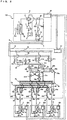
- FIG. 1 is a refrigerant circuit diagram illustrating an example of the refrigerant circuit configuration of an air-conditioning apparatus 100 according to Embodiment 1 of the present invention.
- FIG. 2 is a refrigerant circuit diagram illustrating another example of the refrigerant circuit configuration of the air-conditioning apparatus 100 according to Embodiment 1 of the present invention.
- the circuit configuration and operation of the air-conditioning apparatus 100 will be explained with reference to FIGS. 1 and 2 .
- the air-conditioning apparatus allows each indoor unit to freely select a cooling mode or a heating mode using a refrigeration cycle.
- the size relationship of individual components may be different from the actual size relationship.
- the air-conditioning apparatus 100 includes a heat source unit (outdoor unit) A, a plurality of indoor units C to E connected in parallel, and a relay unit B interposed between the heat source unit A and the indoor units C to E.
- a heat source unit outdoor unit
- the relay unit B interposed between the heat source unit A and the indoor units C to E.
- the illustration is not intended to limit the number of the units connected. For example, two or more heat source units, two or more relay units, and two or more indoor units may be connected.
- the number of operating indoor units connected to the relay unit B may be larger than the number of intermediate heat exchangers within the relay unit B, which will be described later, and even when the number of installed intermediate heat exchangers is equal to the number of connected indoor units, the variation range of the capacity of the intermediate heat exchangers may be different from the variation range of the capacity of the indoor units.
- Embodiment 1 assumes that the capacities of the indoor units C to E are the same and the capacities of the two intermediate heat exchangers are the same.
- a primary-side cycle through which a primary-side heat transfer medium (referred to as refrigerant, hereinafter) circulates is formed between the heat source unit A and the relay unit B
- a secondary-side cycle through which a secondary-side heat transfer medium (referred to as brine, hereinafter) circulates is formed between the relay unit B and each of the indoor units C to E, and heat exchange between the primary-side cycle and the secondary-side cycle is performed in intermediate heat exchangers 9a and 9b arranged within the relay unit B.
- cooling energy and heating energy generated by the heat source unit A are transferred to the indoor units C to E via the intermediate heat exchangers 9a and 9b of the relay unit B.
- a refrigerant used in a vapor-compression heat pump such as a fluorocarbon refrigerant (for example, an HFC-type refrigerant, such as an R32 refrigerant, R125, or R134a, a mixture of the above refrigerants, such as R410A, R407c, R404A, or the like), an HFO refrigerant (for example, HFO-1234yf, HFO-1234ze(E), or HFO-1234ze(Z)), a CO 2 refrigerant, an HC refrigerant (for example, propane or isobutane refrigerant), an ammonia refrigerant, or a mixed refrigerant of the above refrigerants, such as a mixed refrigerant of R32 and HFO-1234yf, may be used.
- a fluorocarbon refrigerant for example, an HFC-type refrigerant, such as an R32 refrigerant, R125, or R134a, a mixture
- the heat source unit A is typically positioned in a space outside a construction, such as a building (for example, a rooftop or the like), and supplies cooling energy or heating energy to the indoor units C to E via the relay unit B.
- a building for example, a rooftop or the like
- the heat source unit A need not be installed outdoors.
- the heat source unit A may be installed in an enclosed space, such as a machine room equipped with a ventilation opening.
- the heat source unit A may be installed inside a construction as long as waste heat can be exhausted outside the construction via an exhaust duct.
- a heat source unit A of a water-cooled type may be installed inside a construction.
- the area in which the heat source unit A is installed is irrelevant to any particular problem involved.
- the heat source unit A includes a compressor 1, a four-way valve 2, which serves as a first flow passage switching valve that switches the direction in which a refrigerant circulates, a heat-source-side heat exchanger 3, and an accumulator 4.
- the above-mentioned components are connected by a first refrigerant pipe 6 and a second refrigerant pipe 7.
- a flow control device 3-m for controlling the flow rate of fluid that exchanges heat with a refrigerant is installed.
- a heat-source-side heat exchanger 3 of an air-cooled type will be explained as an example of the heat-source-side heat exchanger 3 and a fan 3-m will be explained as an example of the flow control device 3-m.
- a heat-source-side heat exchanger 3 of another type such as a water-cooled type (in this case, the flow control device 3-m is a pump), may be used as long as a refrigerant exchanges heat with another fluid.
- a method for controlling the compressor 1 and the fan 3-m, and a method for switching the four-way valve 2 will be described later.
- the heat source unit A also includes a first connecting pipe 60A, a second connecting pipe 60B, a check valve 14, a check valve 16, a check valve 17, and a check valve 15.
- a high-pressure refrigerant flows out of the heat source unit A via the first refrigerant pipe 6 and a low-pressure refrigerant flows into the heat source unit A via the second refrigerant pipe 7, regardless of the direction in which the four-way valve 2 is connected.
- the compressor 1 sucks a heat-source-side refrigerant and compresses the heat-source-side refrigerant into a high-temperature and high-pressure state, and is desirably configured as, for example, a capacity-controllable inverter compressor or the like.
- the four-way valve 2 switches between the flow of the heat-source-side refrigerant at the time of a heating operation (in a heating only operation mode and a heating main operation mode) and the flow of the heat-source-side refrigerant at the time of a cooling operation (in a cooling only operation mode and a cooling main operation mode).
- the heat-source-side heat exchanger (outdoor heat exchanger) 3 functions as an evaporator during a heating operation while functioning as a condenser (or a radiator) during a cooling operation, exchanges heat between air supplied from the fan 3-m and the heat-source-side refrigerant, and transforms the heat-source-side refrigerant into vapor or condensate according to the circumstances involved.
- the accumulator 4 is provided on the suction side of the compressor 1, and stores an excess refrigerant generated due to the difference between a heating operation and a cooling operation or an excess refrigerant generated due to a transient change in operation.
- the check valve 14 is provided at the first refrigerant pipe 6 between the heat-source-side heat exchanger 3 and the relay unit B, and allows the heat-source-side refrigerant to flow only in a predetermined direction (the direction from the heat source unit A to the relay unit B).
- the check valve 15 is provided at the second refrigerant pipe 7 between the relay unit B and the four-way valve 2, and allows the heat-source-side refrigerant to flow only in another predetermined direction (the direction from the relay unit B to the heat source unit A).
- the check valve 16 is provided at the first connecting pipe 60a, and causes the heat-source-side refrigerant discharged from the compressor 1 to circulate to the relay unit B during a heating operation.
- the check valve 17 is provided at the connecting pipe 60b, and causes the heat-source-side refrigerant returned from the relay unit B to circulate to the suction side of the compressor 1 during a heating operation.
- the first connecting pipe 60a connects between the second refrigerant pipe 7 between the four-way valve 2 and the check valve 15, and the first refrigerant pipe 6 between the check valve 14 and the relay unit B, within the heat source unit A.
- the second connecting pipe 60b connects between the second refrigerant pipe 7 between the check valve 15 and the relay unit B, and the first refrigerant pipe 6 between the heat-source-side heat exchanger 3 and the check valve 14, within the heat source unit A.
- the heat source unit A moreover includes a pressure gauge 31, a pressure gauge 32, and a thermometer 41.
- the pressure gauge 31 is provided on the discharge side of the compressor 1 and measures the pressure of the refrigerant discharged from the compressor 1.
- the pressure gauge 32 is provided on the suction side of the compressor 1 and measures the pressure of the refrigerant sucked into the compressor 1.
- thermometer 41 is provided in the vicinity of the heat-source-side heat exchanger 3 and measures the temperature of the outside air taken in by the fan 3-m.
- the pieces of information (temperature information and pressure information) detected by the above-mentioned detection devices are sent to a controller (for example, control means 50) that performs overall control of the operation of the air-conditioning apparatus 100, and are used to control each actuator.
- the relay unit B is installed in, for example, a space on, for example, the lower side of the roof, which is formed inside a construction but is different from an indoor space, and transfers, to the indoor units C to E, cooling energy or heating energy supplied from the heat source unit A.
- the relay unit B may be installed in a shared space in which an elevator or the like is installed, or the like.
- the relay unit B includes a first branch portion 8a into which a high-pressure refrigerant flows from the heat source unit A, a second branch portion 8b from which a low-pressure refrigerant flows out towards the heat source unit A, and a third branch portion 8c in which the refrigerant has an intermediate pressure.
- the relay unit B includes a fourth branch portion 8d and a fifth branch portion 8e corresponding to the high-pressure side of brine, and a sixth branch portion 8f and a seventh branch portion 8g corresponding to the low-pressure side of brine.
- the relay unit B includes the first intermediate heat exchanger 9a and the second intermediate heat exchanger 9b which exchange heat between a refrigerant and a second refrigerant, a first pump 18a and a second pump 18b which drive the second refrigerant, a first flow control device 10a which controls the flow rate of the refrigerant, a second flow control device 10b which controls the flow rate of the refrigerant, a third flow control device 12a which controls the flow rate of the refrigerant, a fourth flow control device 12b which controls the flow rate of the refrigerant, and a refrigerant-refrigerant heat exchanger 13 which exchanges heat between refrigerants.
- the first refrigerant pipe 6 is branched in order to connect the first refrigerant pipe 6 to each of the intermediate heat exchangers 9a and 9b.
- the second refrigerant pipe 7 is branched in order to connect the second refrigerant pipe 7 to each of the intermediate heat exchangers 9a and 9b.
- the third branch portion 8c is provided between the first flow control device 10a and the second flow control device 10b, and the third flow control device 12a and the fourth flow control device 12b, and connects the intermediate heat exchangers 9a and 9b in series or in parallel.
- a first solenoid valve 11a is provided at the pipe between the first branch portion 8a and the intermediate heat exchanger 9a.
- a second solenoid valve 11b is provided at the pipe between the first branch portion 8a and the intermediate heat exchanger 9b.
- a third solenoid valve 11c is provided at the pipe between the second branch portion 8b and the intermediate heat exchanger 9a.
- a fourth solenoid valve 11d is provided at the pipe between the second branch portion 8b and the intermediate heat exchanger 9b.
- the first solenoid valve 11a, the second solenoid valve 11b, the third solenoid valve 11c, and the fourth solenoid valve 11d each operate as a third flow passage switching valve for selectively switching the connection of the intermediate heat exchanger 9a or 9b between a condenser and an evaporator, and each allow the intermediate heat exchanger 9a or 9b to be switchably connected to the first branch portion 8a or the second branch portion 8b.
- the first solenoid valve 11a and the third solenoid valve 11c are installed on a side opposite to the side of the first flow control device 10a with respect to the intermediate heat exchanger 9a. Furthermore, the second solenoid valve 11b and the fourth solenoid valve 11d are installed on a side opposite to the side of the second flow control device 10b with respect to the intermediate heat exchanger 9b.
- the flow of refrigerant in the intermediate heat exchangers 9a and 9b will be explained later in Circuit Configuration.
- the fourth branch portion 8d branches the brine that has flowed out of the intermediate heat exchanger 9a into the first brine pipes 6c, 6d, and 6e.
- the fifth branch portion 8e branches the brine that has flowed out of the intermediate heat exchanger 9b into the first brine pipes 6c, 6d and 6e.
- the sixth branch portion 8f combines the brines that have flowed through the second brine pipes 7c, 7d and 7e together, and allows the combined brine to flow into the intermediate heat exchanger 9a.
- the seventh branch portion 8g combines the brines that have flowed through the second brine pipes 7c, 7d and 7e together, and allows the combined brine to flow into the intermediate heat exchanger 9b.
- a switching valve 19c is installed at the first brine pipe 6c between the fourth branch portion 8d and an indoor heat exchanger (use-side heat exchanger) 5c.
- a switching valve 19d is installed at the first brine pipe 6d between the fourth branch portion 8d and an indoor heat exchanger 5d.
- a switching valve 19e is installed at the first brine pipe 6e between the fourth branch portion 8d and an indoor heat exchanger 5e.
- a switching valve 19f is installed at the first brine pipe 6c between the fifth branch portion 8e and the indoor heat exchanger 5c.
- a switching valve 19g is installed at the first brine pipe 6d between the fifth branch portion 8e and the indoor heat exchanger 5d.
- a switching valve 19h is installed at the first brine pipe 6e between the fifth branch portion 8e and the indoor heat exchanger 5e.
- the switching valves 19c, 19d, 19e, 19f, 19g, and 19h operate as second flow passage switching valves that switch the flow passage of brine, and allow the indoor units C to E to be switchably connected to the fourth branch portion 8d or the fifth branch portion 8e.
- a switching valve 19i is installed at the second brine pipe 7c between the sixth branch portion 8f and the indoor heat exchanger 5c.
- a switching valve 19j is installed at the second brine pipe 7d between the sixth branch portion 8f and the indoor heat exchanger 5d.
- a switching valve 19k is installed at the second brine pipe 7e between the sixth branch portion 8f and the indoor heat exchanger 5e.
- a switching valve 191 is installed at the second brine pipe 7c between the seventh branch portion 8g and the indoor heat exchanger 5c.
- a switching valve 19m is installed at the second brine pipe 7d between the seventh branch portion 8g and the indoor heat exchanger 5d.
- a switching valve 19n is installed at the second brine pipe 7e between the seventh branch portion 8g and the indoor heat exchanger 5e.
- the switching valves 19i, 19j, 19k, 191, 19m, and 19n operate as second flow passage switching valves which switch the flow passage of brine, and allow the indoor units C to E to be switchably connected to the sixth branch portion 8f or the seventh branch portion 8g.
- Embodiment 1 the case in which two sets of intermediate heat exchangers, flow control devices, and pumps are installed will be exemplified.
- the number of the components installed is not limited to that as illustrated. That is, the air-conditioning apparatus 100 includes a plurality of intermediate heat exchangers installed to be capable of a cooling and heating simultaneous operation.
- the heat exchange capacities for cooling and heating of the intermediate heat exchangers can be stably, continuously switched according to the load of an indoor unit.
- the relay unit B includes thermometers 33a to 33d that measure the temperatures of refrigerant at the inlets and outlets of the intermediate heat exchangers 9a and 9b, a thermometer 33e that measures the temperature of refrigerant between the refrigerant-refrigerant heat exchanger 13 and the second branch portion 8b, thermometers 34a and 34b that measure the temperatures of brine on the downstream sides of the first pump 18a and the second pump 18b, respectively, and thermometers 34c to 34e that measure the temperatures of brine between the indoor heat exchangers 5c to 5e and flow control devices 20c to 20e, respectively.
- the pieces of information (temperature information) detected by the above-mentioned detection devices are sent to a controller (for example, control means 51) that performs overall control of the operation of the air-conditioning apparatus 100, and are used to control each actuator.
- a controller for example, control means 51
- the indoor units C to E are each installed at a position from which conditioned air can be supplied to an air-conditioning target space, such as an indoor space, and each supply cooling air or heating air to the air-conditioning target space using cooling energy or heating energy from the heat source unit A transferred via the relay unit B.
- the indoor heat exchanger 5 is mounted in each of the indoor units C to E. Reference symbols c to e are assigned to the indoor heat exchangers 5 in correspondence with the indoor units C to E, respectively.
- the indoor heat exchanger 5c is connected to the sixth branch portion 8f or the seventh branch portion 8g of the relay unit B via the second brine pipe 7c, and is connected to the fourth branch portion 8d or the fifth branch portion 8e of the relay unit B via the first brine pipe 6c.
- the indoor heat exchanger 5d is connected to the sixth branch portion 8f or the seventh branch portion 8g of the relay unit B via the second brine pipe 7d, and is connected to the fourth branch portion 8d or the fifth branch portion 8e of the relay unit B via the first brine pipe 6d.
- the indoor heat exchanger 5e is connected to the sixth branch portion 8f or the seventh branch portion 8g of the relay unit B via the second brine pipe 7e, and is connected to the fourth branch portion 8d or the fifth branch portion 8e of the relay unit B via the first brine pipe 6e.
- the indoor heat exchangers 5 each exchange heat between air supplied from an air-sending device of a fan 5-m and a heat medium, and generate heating air or cooling air to be supplied to the air-conditioning target space. Furthermore, in the vicinity of each of the indoor heat exchangers 5, a flow control device 5-m that controls the flow rate of fluid that exchanges heat with refrigerant is installed.
- indoor heat exchangers 5 of an air-cooled type will be taken as an example of the indoor heat exchangers 5, and fans 5-m will be taken as an example of the flow control devices 5-m.
- indoor heat exchangers 5 of a different type such as a water-cooled type (in this case, the flow control devices 5-m are pumps), may be used as long as refrigerant exchanges heat with another fluid.
- Reference symbols c to e are assigned to the fans 5-m in correspondence with the indoor units C to E, respectively.
- Thermometers 42-c to 42-e that measure the current temperatures of air-conditioning target spaces, such as indoor spaces, are provided in the indoor units C to E, respectively.
- the pieces of information (temperature information) detected by these detection devices are sent to controllers (for example, control means 52c, 52d, and 52e) that perform overall control of the operation of the air-conditioning apparatus 100, and are used to control each actuator.
- a narrow pipe that connects between the heat-source-side heat exchanger 3 and the first branch portion 8a of the relay unit B is referred to as the first refrigerant pipe 6.
- Pipes that connect between the indoor heat exchangers 5c, 5d, and 5e of the indoor units C, D, and E and the fourth branch portion 8d or the fifth branch portion 8e of the relay unit B are referred to as the first brine pipes 6c, 6d, and 6e.
- the first brine pipes 6c, 6d, and 6e correspond to the first refrigerant pipe 6.
- a pipe that has a width larger than that of the first refrigerant pipe 6 and connects between the four-way valve 2 and the second branch portion 8b of the relay unit B is referred to as the second refrigerant pipe 7.
- Pipes that connect between the indoor heat exchangers 5c, 5d, and 5e of the indoor units C, D, and E and the sixth branch portion 8f or the seventh branch portion 8g of the relay unit B are referred to as the second brine pipes 7c, 7d, and 7e.
- the second brine pipes 7c, 7d, and 7e correspond to the second refrigerant pipe 7.
- the refrigerant flows from the heat source unit A to the relay unit B in the first refrigerant pipe 6 and flows from the relay unit B to the heat source unit A in the second refrigerant pipe 7. Furthermore, brine, serving as the second refrigerant, flows from the relay unit B to the indoor units C to E in the first brine pipes 6c to 6e, respectively, and flows from the indoor units C to E to the relay unit B in the second brine pipes 7c to 7e, respectively.
- the circuit configuration of the primary-side cycle in the heat source unit A and the relay unit B will be explained first.
- the primary-side cycle refers to a cycle through which a refrigerant circulates.
- the four-way valve 2 is selectively switched in accordance with the operation of the heat-source-side heat exchanger 3.
- the four-way valve 2 is switched to the direction represented by the solid lines in the drawing in the case where the heat-source-side heat exchanger 3 operates as a condenser that transfers heat from the refrigerant to air, and is switched to the direction represented by the broken lines in the drawing in the case where the heat-source-side heat exchanger 3 operates as an evaporator that receives heat from air.
- the heat-source-side heat exchanger 3 can rather be said to act as a radiator.
- the heat-source-side heat exchanger 3 is described as a condenser, in correspondence with an evaporator.
- both the intermediate heat exchangers 9a and 9b operate as evaporators.
- both the intermediate heat exchangers 9a and 9b operate as condensers.
- one of the intermediate heat exchangers 9a and 9b When operating indoor units out of the indoor units C to E are performing cooling and heating in combination, one of the intermediate heat exchangers 9a and 9b operates as a condenser and the other one of the intermediate heat exchangers 9a and 9b operates as an evaporator.
- the capacities of the intermediate heat exchangers are increased using both the intermediate heat exchangers 9a and 9b as evaporators or condensers, thereby improving their cooling and heating performance.
- the intermediate heat exchangers 9a and 9b operate as condensers. Also, in the case where the third solenoid valve 11c and the fourth solenoid valve 11d are opened and the first solenoid valve 11a and the second solenoid valve 11b are closed, the intermediate heat exchangers 9a and 9b operate as evaporators.
- first solenoid valve 11a and the third solenoid valve 11c are not opened at the same time and the second solenoid valve 11b and the fourth solenoid valve 11d are not opened at the same time, they may be replaced with three-way valves or the like.
- the first flow control device 10a and the second flow control device 10b connect the intermediate heat exchangers 9a and 9b to the third branch portion 8c.
- the first flow control device 10a and the second flow control device 10b are adjusted on the basis of the degree of superheat of refrigerant at the outlet of an intermediate heat exchanger when the intermediate heat exchanger operates as an evaporator, and are adjusted on the basis of the degree of subcooling of refrigerant at the outlet of an intermediate heat exchanger when the intermediate heat exchanger operates as a condenser.
- the evaporating temperature and the condensing temperature necessary to calculate the degree of superheat and the degree of subcooling of refrigerant at the outlet of an intermediate heat exchanger may be calculated from the pieces of information obtained using the pressure gauges 31 and 32 installed within the heat source unit A, which will be described below, or may be calculated by installing pressure gauges at the first branch portion 8a and the second branch portion 8b within the relay unit B and referring to the values detected by the pressure gauges.
- the first solenoid valve 11a and the fourth solenoid valve 11d are opened, the second solenoid valve 11b and the third solenoid valve 11c are opened, the intermediate heat exchanger 9a operates as a condenser, and the intermediate heat exchanger 9b operates as an evaporator.
- the third flow control device 12a connects between the first branch portion 8a and the third branch portion 8c, and adjusts the flow rate of refrigerant bypassing the intermediate heat exchangers 9a and 9b.
- the fourth flow control device 12b connects between the third branch portion 8c and the second branch portion 8b, and adjusts the flow rate of refrigerant bypassing the intermediate heat exchangers 9a and 9b.
- the refrigerant-refrigerant heat exchanger 13 exchanges heat between the refrigerant flowing through the passage between the first flow control device 12a and the third branch portion 8c and the refrigerant flowing through the passage between the fourth flow control device 12b and the second branch portion 8b.
- the refrigerant-refrigerant heat exchanger 13 cools the refrigerant flowing into the first flow control device 10a, the second flow control device 10b, and the fourth flow control device 12b in the case where the intermediate heat exchanger 9a or 9b operates as an evaporator.
- the refrigerant-refrigerant heat exchanger 13 is installed because the refrigerant flowing into a flow control device changes from a two-phase gas-liquid state into a single-liquid-phase state by cooling the refrigerant, thus achieving stable flow control.
- the third flow control device 12a and the fourth flow control device 12b in each operation mode during, for example, a cooling operation, the third flow control device 12a is fully opened, and the opening degree of the fourth flow control device 12b is controlled on the basis of the degree of superheat of the low-pressure-side refrigerant at the outlet of the refrigerant-refrigerant heat exchanger 13 by referring to the thermometer 33e.
- both the third flow control device 12a and the fourth flow control device 12b are fully closed. Moreover, during a heating operation, the third flow control device 12a is fully closed, and the fourth flow control device 12b is fully opened.
- the third flow control device 12a does not adjust the flow rate of the refrigerant bypassing a condenser. Therefore, the third flow control device 12a may be an opening and closing valve, such as a solenoid valve, as illustrated in FIG. 1 . Furthermore, the refrigerant-refrigerant heat exchanger 13 may be omitted, and a refrigerant circuit may be arranged in such a manner that the refrigerant flowing out of the intermediate heat exchanger 9a serving as a condenser passes through the refrigerant-refrigerant heat exchanger 13 into the third branch portion 8c during a cooling and heating simultaneous operation.
- the third flow control device 12a may be an opening and closing valve, such as a solenoid valve, as illustrated in FIG. 1 .
- the refrigerant-refrigerant heat exchanger 13 may be omitted, and a refrigerant circuit may be arranged in such a manner that the refrigerant flowing out of the intermediate heat exchanger 9a serving as a con
- the circuit configuration of the secondary-side cycle in the relay unit B will be explained next.
- the secondary-side cycle is a cycle through which the second refrigerant circulates.
- the intermediate heat exchangers 9a and 9b are connected by pipes in such a manner that the flow of the refrigerant in the primary-side cycle and the flow of brine in the secondary-side cycle are opposed to each other in the case where the intermediate heat exchangers 9a and 9b operate as condensers.
- flow passage switching valves 21a and 21b that change the flow of brine in an intermediate heat exchanger may not be attached at the intermediate heat exchanger 9a but may be attached only at the intermediate heat exchanger 9b operating as an evaporator during a cooling and heating simultaneous operation.
- the intermediate heat exchanger 9b operates as an evaporator
- the flow of the refrigerant and the flow of brine are opposed to each other in portions other than the intermediate heat exchanger 9a during a cooling operation. Therefore, the cooling capacity can be efficiently improved while suppressing an increase in cost.
- first pump 18a and the second pump 18b of an inverter type are connected in proximity to the intermediate heat exchangers 9a and 9b and are connected to the fourth branch portion 8d and the fifth branch portion 8e, respectively. Furthermore, the other pipes for the intermediate heat exchangers 9a and 9b are connected to the sixth branch portion 8f and the seventh branch portion 8g, respectively.
- the position of the first pump 18a and the position of the intermediate heat exchanger 9a in the secondary-side cycle may be inverted.
- the position of the second pump 18b and the position of the intermediate heat exchanger 9b in the secondary-side cycle may be inverted.
- the switching valves 19c to 19n may be connected to either intermediate heat exchanger or all of them may be opened so that brine flows into the switching valves from both intermediate heat exchangers.
- the switching valves 19c to 19n are operated in such a manner that an indoor unit performing cooling is connected to the intermediate heat exchanger 9b operating as an evaporator and an indoor unit performing heating is connected to the intermediate heat exchanger 9a operating as a condenser.
- the flow control devices 20c to 20e that adjust the flow rates of brine flowing into corresponding indoor units are installed at the second brine pipes 7c to 7e between the indoor heat exchangers 5c to 5e and the switching valves switching valves 19i to 19n.
- the flow control devices 20c to 20e may be installed on the side of the first brine pipes 6c to 6e.
- the opening degrees of the flow control devices 20c to 20e are controlled such that, for example, the differences in temperature of brine at inlets and outlets of the indoor units C to E stay constant.
- control may be performed such that the differences between the temperatures become equal to a predetermined value.
- thermometers 34a and 34b arranged on the downstream side of the first pump 18a and the second pump 18b, respectively.
- temperatures of the brine returning from the indoor units C to E to the relay unit B can be measured by the thermometers 34c to 34e provided between the indoor heat exchangers 5c to 5e and the flow control devices 20c to 20e.
- the target value for the temperature difference is set to about 3 °C to 7 °C for a cooling operation, as described in Patent Literature 2.
- the control target value larger in a heating operation than in cooling, an efficient operation can be achieved.
- the first pump 18a and the second pump 18b may be driven at a constant speed.
- control can be performed by changing the pump capacity in such a manner that the opening degree of the flow control device whose opening degree is largest is set to, for example, 80 % to 95 % of the maximum opening degree.
- the running operation of the air-conditioning apparatus 100 includes four modes: a cooling operation mode, a heating operation mode, a cooling main operation mode, and a heating main operation mode.
- a cooling operation mode a heating operation mode
- a cooling main operation mode a cooling main operation mode
- a heating main operation mode a heating main operation mode
- a cooling operation is an operation mode in which an indoor unit is capable of only cooling and the indoor unit is performing cooling or is stopped.
- An operation is an operation mode in which an indoor unit is capable of only heating and the indoor unit is performing heating or is stopped.
- a cooling main operation is an operation mode in which each indoor unit is capable of selecting cooling or heating and in a cooling and heating simultaneous operation mode in which an indoor unit performing cooling and an indoor unit performing heating exist at the same time, the cooling load is heavier than heating load, and the heat-source-side heat exchanger 3 is connected to the discharge side of the compressor and operates as a condenser.
- a heating main operation is an operation mode in which in a cooling and heating simultaneous operation, the heating load is heavier than the cooling load, and the heat-source-side heat exchanger 3 is connected to the suction side of the compressor and operates as an evaporator.
- the four-way valve 2 is switched so that the refrigerant discharged from the compressor 1 flows into the heat-source-side heat exchanger 3.
- the third solenoid valve 11c and the fourth solenoid valve 11d are opened, and the first solenoid valve 11a and the second solenoid valve 11b are closed.
- FIG. 3 is a P-h diagram illustrating the transition of refrigerant in a cooling operation. The flow of refrigerant will be explained first, and the flow of brine will be explained next.
- a low-temperature and low-pressure gas refrigerant is compressed by the compressor 1 and is discharged as a high-temperature and high-pressure gas refrigerant.
- compression is performed in such a manner that the refrigerant is heated more than when the refrigerant is adiabatically compressed based on an isentropic line by an amount corresponding to the adiabatic efficiency of the compressor, and is represented by a line extending from point (a) to point (b) in FIG. 3 .
- the high-temperature and high-pressure gas refrigerant discharged from the compressor 1 flows into the heat-source-side heat exchanger 3 via the four-way valve 2. At this time, the refrigerant is cooled while heating outdoor air, and turns into an intermediate-temperature and high-pressure liquid refrigerant.
- the change of the refrigerant in the heat-source-side heat exchanger 3 is represented by a slightly-slanted substantially horizontal straight line extending from point (b) to point (c) in FIG. 3 , in view of pressure loss in the heat-source-side heat exchanger 3.
- the intermediate-temperature and high-pressure liquid refrigerant that has flowed out of the heat-source-side heat exchanger 3 passes through the first refrigerant pipe 6 and the third flow control device 12a, exchanges heat in the refrigerant-refrigerant heat exchanger 13 with the refrigerant that has flowed out of the fourth flow control device 12b, and is cooled.
- the cooling process at this time is represented by a line extending from point (c) to point (d) in FIG. 3 .
- the liquid refrigerant cooled at the refrigerant-refrigerant heat exchanger 13 flows into the first flow control device 10a and the second flow control device 10b while the refrigerant partially bypasses the second branch portion 8b through the fourth flow control device 12b. Then, the high-pressure liquid refrigerant is expanded and decompressed by the first flow control device 10a and the second flow control device 10b, and turns into a low-temperature and low-pressure, two-phase gas-liquid state.
- a change of the refrigerant occurs with a constant enthalpy at the first flow control device 10a and the second flow control device 10b.
- the change of the refrigerant at this time is represented by a vertical line extending from point (d) to point (e) in FIG. 3 .
- the low-temperature and low-pressure refrigerant in the two-phase gas-liquid state that has flowed out of the first flow control device 10a and the second flow control device 10b flows into the first intermediate heat exchanger 9a and the second intermediate heat exchanger 9b. Then, the refrigerant is heated while cooling brine, and turns into a low-temperature and low-pressure gas refrigerant.
- the change of the refrigerant at the first intermediate heat exchanger 9a and the second intermediate heat exchanger 9b is represented by a slightly-slanted substantially horizontal straight line extending from point (e) to point (a) in FIG. 3 , in view of pressure loss.
- the low-temperature and low-pressure gas refrigerants that have flowed out of the first intermediate heat exchanger 9a and the second intermediate heat exchanger 9b pass through the third solenoid valve 11c and the fourth solenoid valve 11d, respectively, and flow into the second branch portion 8b.
- the low-temperature and low-pressure gas refrigerants merge together at the second branch portion 8b.
- the merged refrigerant passes through the second refrigerant pipe 7 and the four-way valve 2, flows into the compressor 1, and is compressed.
- the brines cooled by the refrigerant at the first intermediate heat exchanger 9a and the second intermediate heat exchanger 9b are subjected to pressurization and driven by the first pump 18a and the second pump 18b, and flow into the fourth branch portion 8d and the fifth branch portion 8e.
- the brines flowing into the fourth branch portion 8d and the fifth branch portion 8e are mixed at the switching valves 19c to 19h for brine, and flow into the indoor units C to E through the first brine pipes 6c to 6e on the indoor side.
- the brines cool the indoor air at the indoor heat exchangers 5c to 5e, and cooling is performed.
- the brines are heated by the indoor air, pass through the second brine pipes 7c to 7e on the indoor side, and return to the relay unit B.
- the brines flow into the first intermediate heat exchanger 9a and the second intermediate heat exchanger 9b while being expanded and decompressed by the flow control devices 20c to 20e for brine.
- the four-way valve 2 is switched so that the refrigerant discharged from the compressor 1 flows into the first branch portion 8a.
- the first solenoid valve 11a and the second solenoid valve 11b are opened, and the third solenoid valve 11c and the fourth solenoid valve 11d are closed.
- FIG. 4 is a P-h diagram illustrating the transition of refrigerant in the heating operation. The flow of refrigerant will be explained first, and the flow of brine will be explained next.
- a low-temperature and low-pressure gas refrigerant is compressed by the compressor 1 and is discharged as a high-temperature and high-pressure gas refrigerant.
- the refrigerant compression process by the compressor is represented by a line extending from point (a) to point (b) in FIG. 4 .
- the high-temperature and high-pressure gas refrigerant discharged from the compressor 1 flows into the first branch portion 8a through the four-way valve 2 and the first refrigerant pipe 6.
- the high-temperature and high-pressure gas refrigerant that has flowed into the first branch portion 8a is branched at the first branch portion 8a, and the branched refrigerants pass through the first solenoid valve 11a and the second solenoid valve 11b, and flow into the first intermediate heat exchanger 9a and the second intermediate heat exchanger 9b.
- the refrigerants are cooled while heating brine, and turn into intermediate-temperature and high-pressure liquid refrigerants.
- the change of the refrigerants in the first intermediate heat exchanger 9a and the second intermediate heat exchanger 9b is represented by a slightly-slanted substantially horizontal straight line extending from point (b) to point (c) in FIG. 4 .
- the high-pressure liquid refrigerants are expanded and decompressed at the first flow control device 10a, the second flow control device 10b, and the fourth flow control device 12b, and turn into a low-temperature and low-pressure, two-phase gas-liquid state.
- the change of the refrigerants at this time is represented by a vertical line extending from point (c) to point (d) in FIG. 4 .
- the low-temperature and low-pressure refrigerant in the two-phase gas-liquid state that has flowed out of the fourth flow control device 12b passes through the second refrigerant pipe 7, flows into the heat-source-side heat exchanger 3, is heated while cooling the outdoor air, and turns into a low-temperature and low-pressure gas refrigerant.
- the change of the refrigerant at the heat-source-side heat exchanger 3 is represented by a slightly-slanted substantially horizontal straight line extending from point (d) to point (a) in FIG. 4 .
- the low-temperature and low-pressure gas refrigerant that has flowed out of the heat-source-side heat exchanger 3 passes through the four-way valve 2, flows into the compressor 1, and is compressed.
- the flow of brine is substantially similar to that at the time of a cooling operation. Since all the indoor units C, D, and E are performing heating, the switching valves 19c to 19h and 19i to 19n for brine are opened, and brines travel from the fourth branch portion 8d and the fifth branch portion 8e to the first brine pipes 6c to 6e on the indoor side and from the second brine pipes 7c to 7e on the indoor side to the sixth branch portion 8f and the seventh branch portion 8g.
- the brines heated by refrigerants at the first intermediate heat exchanger 9a and the second intermediate heat exchanger 9b are subjected to pressurization and driven at the first pump 18a and the second pump 18b, and flow into the fourth branch portion 8d and the fifth branch portion 8e.
- the brines that have flowed into the fourth branch portion 8d and the fifth branch portion 8e are mixed by the switching valves 19c to 19h for brine, and pass through the first brine pipes 6c to 6e on the indoor side and flow into the indoor units C to E.
- the brines heat the indoor air at the indoor heat exchangers 5c to 5e, and heating is performed.
- the brines are cooled by the indoor air, pass through the second brine pipes 7c to 7e on the indoor side, and return to the relay unit B.
- the brines flow into the first and second intermediate heat exchangers 9a and 9b while being expanded and decompressed by the flow control devices 20c to 20e for brine.
- the four-way valve 2 is switched so that the refrigerant discharged from the compressor 1 flows into the heat-source-side heat exchanger 3.
- the first solenoid valve 11a and the fourth solenoid valve 11d are opened, and the second solenoid valve 11b and the third solenoid valve 11c are closed.
- FIG. 5 is a P-h diagram illustrating the transition of refrigerant in the cooling main operation. The flow of refrigerant will be explained first, and the flow of brine will be explained next.
- a low-temperature and low-pressure gas refrigerant is compressed by the compressor 1, and is discharged as a high-temperature and high-pressure gas refrigerant.
- the refrigerant compression process by the compressor is represented by a line extending from point (a) to point (b) in FIG. 5 .
- the high-temperature and high-pressure gas refrigerant discharged from the compressor 1 flows into the heat-source-side heat exchanger 3 via the four-way valve 2. At this time, in the heat-source-side heat exchanger 3, the refrigerant is cooled while heating the outdoor air with a heat quantity necessary for heating being left intact, and turns into an intermediate-temperature and high-pressure, two-phase gas-liquid state.
- the change of the refrigerant at the heat-source-side heat exchanger 3 is represented by a slightly-slanted substantially horizontal straight line extending from point (b) to point (c) in FIG. 5 .
- the intermediate-temperature and high-pressure, two-phase gas-liquid refrigerant that has flowed out of the heat-source-side heat exchanger 3 passes through the first refrigerant pipe 6, the first branch portion 8a, and the first solenoid valve 11a, and flows into the first intermediate heat exchanger 9a. Then, the refrigerant is cooled while heating brine, and turns into an intermediate-temperature and high-pressure liquid refrigerant.
- the change of the refrigerant at the first intermediate heat exchanger 9a is represented by a slightly-slanted substantially horizontal straight line extending from point (c) to point (d) in FIG. 5 .
- the refrigerant that has flowed out of the intermediate heat exchanger 9a is expanded and decompressed by the first flow control device 10a.
- the change of the refrigerant at this time is represented by a vertical line extending from point (d) to point (e) in FIG. 5 .
- the refrigerant is further expanded and decompressed by the second flow control device 10b, and turns into a low-temperature and low-pressure, two-phase gas-liquid state.
- the change of the refrigerant at this time is represented by a vertical line extending from point (e) to point (f) in FIG. 5 .
- the low-temperature and low-pressure refrigerant in the two-phase gas-liquid state that has flowed out of the second flow control device 10b flows into the second intermediate heat exchanger 9b. Then, the refrigerant is heated while cooling brine, and turns into a low-temperature and low-pressure gas refrigerant.
- the change of the refrigerant at the second intermediate heat exchanger 9b is represented by a slightly-slanted substantially horizontal straight line extending from point (f) to point (a) in FIG. 5 , in view of pressure loss.
- the low-temperature and low-pressure gas refrigerant that has flowed out of the second intermediate heat exchanger 9b passes through the fourth solenoid valve 11d and flows into the second branch portion 8b.
- the low-temperature and low-pressure gas refrigerant that has flowed into the second branch portion 8b passes through the second refrigerant pipe 7 and the four-way valve 2, flows into the compressor 1, and is compressed.
- the first flow control device 10a at this time may be controlled such that the degree of subcooling of the refrigerant at the outlet of the first intermediate heat exchanger 9a reaches a predetermined value, and the second flow control device 10b can be set to be fully opened.
- the fourth flow control device 12b may be controlled such that the pressure at the third branch portion 8c stays constant
- the first flow control device 10a may be controlled such that the degree of subcooling of the refrigerant at the outlet of the first intermediate heat exchanger 9a reaches a predetermined value
- the second flow control device 10b may be controlled such that the degree of superheat of the refrigerant at the outlet of the first intermediate heat exchanger 9a stays constant.
- the brine heated by the refrigerant at the first intermediate heat exchanger 9a is subjected to pressurization and driven by the first pump 18a, and flows into the fourth branch portion 8d.
- the brine that has flowed into the fourth branch portion 8d passes through the switching valve 19e for brine and the first brine pipe 6e on the indoor side, and flows into the indoor unit E.
- the brine heats the indoor air at the indoor heat exchanger 5e, and heating is performed.
- the brine is cooled by the indoor air, passes through the second brine pipe 7e on the indoor side, and returns to the relay unit B.
- the brine flows into the first intermediate heat exchanger 9a while being expanded and decompressed by the flow control device 20e for brine.
- the brine cooled by the refrigerant at the second intermediate heat exchanger 9b is subjected to pressurization and driven by the second pump 18b, and flows into the fifth branch portion 8e.
- the brine that has flowed into the fifth branch portion 8e passes through the switching valves 19f and 19g for brine and the first brine pipes 6c and 6d on the indoor side, and flows into the indoor units C and D.
- the brine cools the indoor air at the indoor heat exchangers 5c and 5d, and cooling is performed. At the time of cooling, the brine is heated by the indoor air, passes through the second brine pipes 7c and 7d on the indoor side, and returns to the relay unit B. The brine flows into the second intermediate heat exchanger 9b while being expanded and decompressed by the flow control devices 20c and 20d for brine.
- the four-way valve 2 is switched so that refrigerant discharged from the compressor 1 is caused to flow into the first branch portion 8a.
- the first solenoid valve 11a and the fourth solenoid valve 11d are opened, and the second solenoid valve 11b and the third solenoid valve 11c are closed.
- FIG. 6 is a P-h diagram illustrating the transition of refrigerant in the heating main operation. The flow of refrigerant will be explained first, and the flow of brine will be explained next.
- the low-temperature and low-pressure gas refrigerant is compressed by the compressor 1, and is discharged as a high-temperature and high-pressure gas refrigerant.
- the refrigerant compression process by the compressor is represented by a line extending from point (a) to point (b) in FIG. 6 .
- the high-temperature and high-pressure gas refrigerant discharged from the compressor 1 flows into the first branch portion 8a through the four-way valve 2 and the first refrigerant pipe 6.
- the high-temperature and high-pressure gas refrigerant that has flowed into the first branch portion 8a passes through the first branch portion 8a and the first solenoid valve 11a, and flows into the first intermediate heat exchanger 9a.
- the change of the refrigerant at the first intermediate heat exchanger 9a is represented by a slightly-slanted substantially horizontal straight line extending from point (b) to point (c) in FIG. 6 .
- the refrigerant that has flowed out of the first intermediate heat exchanger 9a is expanded and decompressed by the first flow control device 10a and the second flow control device 10b.
- the change of the refrigerant at this time is represented by a vertical line extending from point (c) to point (d) in FIG. 6 .
- the low-temperature and low-pressure refrigerant in the two-phase gas-liquid state that has flowed out of the second flow control device 10b flows into the second intermediate heat exchanger 9b.
- the refrigerant is heated while cooling brine by a heating quantity necessary for an indoor unit, and turns into a low-temperature and low-pressure refrigerant.
- the change of the refrigerant at the second intermediate heat exchanger 9b is represented by a slightly-slanted substantially horizontal straight line extending from point (d) to point (e) in FIG. 6 , in view of pressure loss.
- the low-temperature and low-pressure refrigerant that has flowed out of the second intermediate heat exchanger 9b passes through the second refrigerant pipe 7, flows into the heat-source-side heat exchanger 3, is heated while cooling the outdoor air, and turns into a low-temperature and low-pressure gas refrigerant.
- the change of the refrigerant at the heat-source-side heat exchanger 3 is represented by a slightly-slanted substantially horizontal straight line extending from point (e) to point (a) in FIG. 6 .
- the low-temperature and low-pressure gas refrigerant that has flowed out of the heat-source-side heat exchanger 3 passes through the four-way valve 2, flows into the compressor 1, and is compressed.
- the first flow control device 10a at this time may be controlled such that the degree of subcooling of the refrigerant at the outlet of the first intermediate heat exchanger 9a reaches a predetermined value, and the second flow control device 10b can be set to be fully opened.
- the fourth flow control device 12b for example, by operating the fourth flow control device 12b so that the pressure at the third branch portion 8c stays constant, causing the liquid refrigerant to be split at the third branch portion 8c, controlling the first flow control device 10a so that the degree of subcooling of the refrigerant at the outlet of the first intermediate heat exchanger 9a reaches a predetermined value, and controlling the second flow control device 10b so that the degree of superheat of the refrigerant at the outlet of the first intermediate heat exchanger 9a reaches a predetermined value, the flow rate of the refrigerant flowing into the second intermediate heat exchanger 9b can be adjusted, thereby enabling load adjustment to be smoothly performed.
- point (f) represents the state of the refrigerant at the outlet of the second intermediate heat exchanger 9b
- point (g) represents the state of the refrigerant that has flowed out of the fourth flow control device 12b
- point (e) represents the state after the refrigerant at point (f) and the refrigerant at point (g) merge together at the first branch portion.
- FIG. 7 is a P-h diagram illustrating another example of the transition of refrigerant in the heating main operation.
- the flow of brine is substantially the same as that in the explanation of the flow of brine in the cooling main operation, and only connection of the indoor unit D is changed from the second intermediate heat exchanger 9b to the first intermediate heat exchanger 9a. Therefore, an explanation of the flow of brine will be omitted.
- the heat source unit A includes the control means 50
- the relay unit B includes the control means 51
- the indoor units C to E include the control means 52c to 52e, respectively.
- the control means is installed in each of the heat source unit A, the relay unit B, and the indoor units C to E.
- control means is integrated into one unit and actuators are controlled by communicating control values among individual units.
- control means 50, 51, and 52c to 52e will sometimes be collectively referred to as control means.
- the control means 52c to 52e perform driving control, such as operation, stopping, and the like of fan motors for the fans 5c-m to 5e-m on the basis of the settings of remote control for the indoor units C to E and the current indoor temperature.
- control means 51 performs setting of the opening degree of flow control devices, switching of solenoid valves, and driving of pumps in the relay unit B, in accordance with the operation mode based on the operation capacity for cooling and heating of the indoor units C to E.
- control means 50 performs driving of the compressor 1, switching of the four-way valve 2, and driving control of the fan motor for the fan 3-m.
- the compressor 1 and the fan motor for the fan 3-m are controlled, for example, as described in Patent Literature 1, on the basis of the pressure gauges 31 and 32 attached to the input and output channels of the compressor 1, so that a fixed target pressure is reached.
- connection of the four-way valve 2 is switched.
- suction pressure cannot be controlled during a heating main operation
- connection of the four-way valve 2 is switched. Accordingly, the operation mode is switched between the cooling main operation and the heating main operation.
- the capacities of the intermediate heat exchangers 9a and 9b may not be continuous with respect to a change in the number of operating indoor units among the indoor units C to E during a cooling and heating simultaneous operation and, therefore, the required heat exchange amount in one of the intermediate heat exchangers 9a and 9b may be increased.
- two intermediate heat exchangers are provided for three indoor units.
- a plurality of small-capacity indoor units are connected, for example, in a cooling main operation based on an indoor capacity of 90 % on cooling and 10 % on heating, although load is reduced by only 10 % compared to the case of 100 % on cooling, the capacity of an intermediate heat exchanger for cooling is halved, thus increasing the load of the intermediate heat exchanger.
- control is performed such that the evaporating temperature is set low by reducing the suction pressure at the compressor 1.
- control is performed such that the evaporating temperature is set low by reducing the suction pressure at the compressor 1.
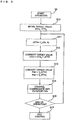
- FIG. 8 illustrates a control flow at the time of a cooling main operation.
- FIG. 8 is a flowchart illustrating the flow of a control process at the time of a cooling main operation of the air-conditioning apparatus 100.
- the case where each type of control is performed by the control means 50, 51, and 52c to 52e communicating with each other will be explained as an example.
- Step S1 the control means starts operation control.
- Step S2 since, typically, the evaporating temperature of a refrigeration cycle needs to be about 10 °C to perform cooling and the condensing temperature needs to be about 40 °C to 50 °C to perform heating, the control means sets an initial value ETm0 of a target value for the evaporating temperature and an initial value CTm0 of a target value for the condensing temperature by taking pressure loss of refrigerant generated in the interval from the heat source unit A to the relay unit B into consideration for the above values.
- the cooling load may be increased with respect to the capacity of the intermediate heat exchanger 9b operating as an evaporator during a cooling main operation.
- Step S3 the control means performs the following operation.
- At is the heat transfer area of the intermediate heat exchangers 9a and 9b at the time of a cooling operation
- Arc is the heat transfer area of the intermediate heat exchanger 9b operating as an evaporator at the time of a cooling main operation
- Qct is the rated load of cooling
- Qc is the current cooling load
- the log-mean temperature difference between brine and refrigerant can be set to increase by the reciprocal of the cooling load ratio (Qc / Qct) and the reduction (Ar / At) in the heat transfer area, and the evaporating temperature can be set to reduce.
- Qc / Qct the cooling load ratio
- Ar / At the reduction
- dTc the log-mean temperature difference between refrigerant and brine at the time of a rated operation in an intermediate heat exchanger.
- Step S4 the control means updates the target value Etm for the evaporating temperature.
- the control means converts the target values for the evaporating temperature and the condensing temperature into pressures according to the physical property of refrigerant.
- the control means controls the frequency of the compressor 1 and the capacity of the heat-source-side heat exchanger 3 so that the discharge and suction pressures reach the target values.
- FIG. 9 illustrates a control method in a heating main operation.
- FIG. 9 is a flowchart illustrating the flow of a control process at the time of a heating main operation of the air-conditioning apparatus 100.
- control means 50, 51, and 52c to 52e communicating with each other will be exemplified.
- control means 50, 51, and 52c to 52e will be collectively referred to as control means.
- Step S9 to Step S16 in the heating main operation is similar to that in the cooling main operation, and a change amount ⁇ Ctm of the target value for the condensing temperature may be calculated using Expression (3) provided below.
- ⁇ ⁇ CTm Qh / Qht / Arh / At ⁇ 1 ⁇ dTh , where Qh is the current heating load, Qht is the rated load of heating, Arh represents the heat transfer area of a condenser at the time of a heating main operation, At represents the heat transfer area of the intermediate heat exchanger 9a at the time of a heating operation, and dTh represents the log-mean temperature difference between refrigerant and brine at the time of a rated operation in an intermediate heat exchanger.
- an air-conditioning apparatus 100 capable of a cooling and heating simultaneous operation with the configuration described above, operation is performed such that the control target value for the compressor suction pressure at the time of a cooling main operation is set equal to or lower than that at the time of a cooling operation and the control target value for the compressor discharge pressure at the time of a heating main operation is set equal to or higher than that at the time of a heating operation, thereby improving the efficiency and increasing the heating capacity in the individual operation modes.
- ⁇ ETm may be determined based on the capacity of the first pump 18a of a brine circuit for cooling
- ⁇ CTm may be determined based on the capacity of the second pump 18b of a brine circuit for heating.
- the flow rate of brine is reduced, and the target value for the difference in temperature between outlet and inlet of brine is increased to enable flow control.
- the target value for the difference in temperature between outlet and inlet of brine is increased, it is determined that the required capacity is increased, and ⁇ ETm and ⁇ CTm may be determined in such a manner that ET is reduced and CT is increased to interlock with control of a water circuit.
- the air-conditioning apparatus 100 is controlled such that the first intermediate heat exchanger 9a and the second intermediate heat exchanger 9b each operate as an evaporator during a cooling operation, the first intermediate heat exchanger 9a operates as a condenser and the second intermediate heat exchanger 9b operates as an evaporator during a cooling main operation, and thus the number of intermediate heat exchangers operating as evaporators at the time of the cooling operation is greater than in the cooling main operation.
- control is performed such that the first intermediate heat exchanger 9a and the second intermediate heat exchanger 9b each operate as a condenser during a heating operation, the first intermediate heat exchanger 9a operates as a condenser and the second intermediate heat exchanger 9b operates as an evaporator during a heating main operation, and thus the number of intermediate heat exchangers operating as condensers at the time of the heating operation is greater than in the heating main operation.
- control target value for the compressor suction pressure at the time of a cooling main operation is set equal to or lower than that at the time of a cooling operation
- a control target value for the compressor discharge pressure at the time of a heating main operation is set equal to or higher than that at the time of a heating operation, thereby improving the efficiency and increasing the heating capacity in the individual operation modes.
- FIG. 10 is a schematic circuit configuration diagram illustrating an example of a refrigerant circuit configuration of an air-conditioning apparatus 200 according to Embodiment 2 of the present invention.
- the air-conditioning apparatus 200 will be explained with reference to FIG. 10 .
- Embodiment 2 differences from Embodiment 1 will be mainly explained and explanation of the same portions as those in Embodiment 1, such as a refrigerant circuit configuration, will be omitted.
- each operation mode executed by the air-conditioning apparatus 200 is similar to that performed by the air-conditioning apparatus 100 according to Embodiment 1, an explanation of the operation mode executed by the air-conditioning apparatus 200 will be omitted.
- the heat transfer areas of the intermediate heat exchangers 9a and 9b within the relay unit B of the air-conditioning apparatus 200 are different from those of the air-conditioning apparatus 100 illustrated in FIGS. 1 and 2 .
- an intermediate heat exchanger 9b having a larger heat transfer area can be used as an evaporator and an intermediate heat exchanger 9a having a smaller heat transfer area can be used as a condenser during a cooling main operation
- an intermediate heat exchanger 9b having a larger heat transfer area can be used as a condenser and an intermediate heat exchanger 9a having a smaller heat transfer area can be used as an evaporator during a heating main operation.
- the ratio of the heat exchange capacities of the intermediate heat exchangers can be made closer to the load ratio of the indoor units C to E, thereby efficiently improving the capacity of a cooling and heating simultaneous operation. Since the control method is similar to that in Embodiment 1, an explanation of the control method will be omitted.
- operation is performed in such a manner that the control target value for the compressor suction pressure at the time of a cooling main operation is set equal to or lower than that at the time of a cooling operation and the control target value for the compressor discharge pressure at the time of a heating main operation is set equal to or higher than that at the time of a heating operation, thereby improving the efficiency and increasing the heating capacity in the individual operation modes.
- FIG. 11 is a schematic circuit configuration diagram illustrating an example of a refrigerant circuit configuration of an air-conditioning apparatus 300 according to Embodiment 3 of the present invention.
- the air-conditioning apparatus 300 will be explained with reference to FIG. 11 .
- Embodiment 2 differences from Embodiment 1 described above will be mainly explained and an explanation of the same portions as those in Embodiment 1, such as a refrigerant circuit configuration, will be omitted.
- each operation mode executed by the air-conditioning apparatus 300 is similar to that executed by the air-conditioning apparatus 100 according to Embodiment 1, an explanation of the operation mode will be omitted.
- the air-conditioning apparatus 300 is different from the air-conditioning apparatus 100 illustrated in FIGS. 1 and 2 in that the number of pipes connecting the heat source unit A and the relay unit B together is changed from 2 into 3.
- a third refrigerant pipe 22 is installed so that a discharge pipe of the compressor 1 in the heat source unit A and the first branch portion 8a in the relay unit B are connected together.
- the first refrigerant pipe 6 is connected to the third branch portion 8c, and a fifth flow control device 23 for adjusting the flow rate of refrigerant flowing into the heat-source-side heat exchanger 3 is installed between the heat-source-side heat exchanger 3 and the first refrigerant pipe 6.
- the air-conditioning apparatus 300 is different from the air-conditioning apparatus 100 in that in the case where there is an indoor unit performing heating, a refrigerant discharged from the compressor 1 passes through the third refrigerant pipe 22 and is supplied to the intermediate heat exchangers 9a and 9b.
- thermometer is installed between the heat-source-side heat exchanger 3 and the fifth flow control device 23, and the fifth flow control device 23 is controlled such that, for example, the degree of subcooling stays constant based on the difference from the condensing temperature calculated from the discharge pressure of the compressor 1, and in the case where the heat-source-side heat exchanger 3 operates as an evaporator, a thermometer is installed between the heat-source-side heat exchanger 3 and the four-way valve 2, and the fifth flow control device 23 is controlled such that, for example, the degree of superheat stays constant based on the difference from the evaporating temperature calculated from the suction pressure of the compressor 1.
- the other flow of refrigerant is substantially the same as the flow explained using FIGS. 3 to 7 in Embodiment 1. Therefore, an explanation of the flow will be omitted.
- operation is performed in such a manner that the control target value for the compressor suction pressure at the time of a cooling main operation is set equal to or lower than that at the time of a cooling operation and the control target value for the compressor discharge pressure at the time of a heating main operation is set equal to or higher than that at the time of a heating operation, thereby improving the efficiency and increasing the heating capacity in the individual operation modes.
- the air-conditioning apparatus 300 similar to the air-conditioning apparatus 100 according to Embodiment 1, even if the load conditions change, the cooling and heating capacities can be maintained, and operation in the state where the efficiency of cycle, such as a COP, is high can be achieved.
- any number of intermediate heat exchangers may be provided as long as the intermediate heat exchangers are configured to be capable of cooling and/or heating a heat medium and as long as control is performed such that the number of intermediate heat exchangers operating as evaporators during a cooling operation is greater than the number of intermediate heat exchangers operating as evaporators during a cooling main operation and that the number of intermediate heat exchangers operating as condensers during a heating operation is greater than the number of intermediate heat exchangers operating as condensers during a heating main operation.
- control may be performed such that a given upper limit value is specified for the number of intermediate heat exchangers to operate as condensers or condensers in accordance with the load of indoor units.
- each of the number of the first pumps 18a provided and the number of the second pumps 18b provided is not necessarily one.
- a plurality of small-capacity pumps may be connected in series or in parallel.
- the cases where the accumulator 4 is included have been explained in Embodiments 1 to 3, the accumulator 4 is not necessarily provided.
Landscapes
- Engineering & Computer Science (AREA)
- Mechanical Engineering (AREA)
- General Engineering & Computer Science (AREA)
- Chemical & Material Sciences (AREA)
- Combustion & Propulsion (AREA)
- Physics & Mathematics (AREA)
- Thermal Sciences (AREA)
- Air Conditioning Control Device (AREA)
- Other Air-Conditioning Systems (AREA)
Claims (11)
- Klimatisierungsvorrichtung (100, 300), deren Auslegung Folgendes umfasst:- Steuerungseinrichtungen (50, 51, 52c-52e)- eine Wärmequelleneinheit (A), die einen Kompressor (1) beinhaltet,- ein erstes Durchfluss-Umschaltventil (2), das einen Durchfluss eines ersten Kühlmittels umschaltet, und einen wärmequellenseitigen Wärmetauscher (3);- eine Vielzahl von Inneneinheiten (C, D, E), wobei jede einen nutzerseitigen Wärmetauscher (5) beinhaltet; und- eine Relaiseinheit (B), die eine Vielzahl von Zwischenwärmetauschern (9a, 9b), zweite Durchfluss-Umschaltventile (19), die den Betrieb der Inneneinheiten (C, D, E) zwischen Heizen und Kühlen umschalten, und dritte Durchfluss-Umschaltventile (11), welche die Verbindung der Zwischenwärmetauscher (9a, 9b) zwischen einem Kondensator und einem Verdampfer umschalten, beinhaltet,wobei in der Klimatisierungsvorrichtung (100, 300)- ein primärseitiger Kreislauf gebildet wird, durch den ein primärseitiges Wärmeübertragungsmedium zwischen der Wärmequelleneinheit (A) und der Relaiseinheit (B) zirkuliert,- ein sekundärseitiger Kreislauf gebildet wird, durch den ein sekundärseitiges Wärmeübertragungsmedium zwischen der Relaiseinheit (B) und den Inneneinheiten (C, D, E) zirkuliert, und- der Wärmeaustausch zwischen dem primärseitigen Kreislauf und dem sekundärseitigen Kreislauf in den Zwischenwärmetauschern (9a, 9b) erfolgt, wobei, wenn alle in Betrieb befindlichen Inneneinheiten aus der Vielzahl von Inneneinheiten (C, D, E) einen Kühlvorgang ausführen, die Steuerungseinrichtungen so angepasst werden, dass sie Folgendes steuern:- die dritten Durchfluss-Umschaltventile (11), so dass die Anzahl der Zwischenwärmetauscher (9a, 9b), die als Verdampfer betrieben werden, größer ist als in einem Hauptkühlbetrieb, bei dem die Inneneinheit (C, D, E), die den Kühlvorgang ausführt, und die Inneneinheit (C, D, E), die den Aufheizvorgang ausführt, gleichzeitig vorhanden sind, und das erste Durchfluss-Umschaltventil (2) so gesteuert wird, dass der wärmequellenseitige Wärmetauscher (3) arbeitet, indem er mit einer Ausstoßseite des Kompressors (1) verbunden ist, unddadurch gekennzeichnet, dass
während des Hauptkühlbetriebs die Steuerungseinrichtungen so angepasst werden, dass sie- einen Zielwert für einen Ansaugdruck oder eine Verdampfungstemperatur am Kompressor (1) so einstellen, dass diese gleich oder niedriger sind, als in einem Fall, bei dem alle in Betrieb befindlichen Inneneinheiten (C, D, E) den Kühlvorgang ausführen, und eine Frequenz des Kompressors (1) und eine Kapazität des wärmequellenseitigen Wärmetauschers (3) so einstellen, dass sie den Zielwert erreichen. - Klimatisierungsvorrichtung (100, 300), deren Auslegung Folgendes umfasst:- eine Steuerungseinrichtung (50, 51, 52c-52e),- eine Wärmequelleneinheit (A), die einen Kompressor (1) beinhaltet,- ein erstes Durchfluss-Umschaltventil (2), das einen Durchfluss eines ersten Kühlmittels umschaltet, und einen wärmequellenseitigen Wärmetauscher (3);- eine Vielzahl von Inneneinheiten (C, D, E), wobei jede einen nutzerseitigen Wärmetauscher (5) beinhaltet; und- eine Relaiseinheit (B), die eine Vielzahl von Zwischenwärmetauschern (9a, 9b), zweite Durchfluss-Umschaltventile (19), die den Betrieb der Inneneinheiten (C, D, E) zwischen Heizen und Kühlen umschalten, und dritte Durchfluss-Umschaltventile (11), welche die Verbindung der Zwischenwärmetauscher (9a, 9b) zwischen einem Kondensator und einem Verdampfer umschalten, beinhaltet,wobei in der Klimatisierungsvorrichtung (100, 300)- ein primärseitiger Kreislauf gebildet wird, durch den ein primärseitiges Wärmeübertragungsmedium zwischen der Wärmequelleneinheit (A) und der Relaiseinheit (B) zirkuliert,- ein sekundärseitiger Kreislauf gebildet wird, durch den ein sekundärseitiges Wärmeübertragungsmedium zwischen der Relaiseinheit (B) und den Inneneinheiten (C, D, E) zirkuliert, und- der Wärmeaustausch zwischen dem primärseitigen Kreislauf und dem sekundärseitigen Kreislauf in den Zwischenwärmetauschern (9a, 9b) erfolgt, wobei, wenn alle in Betrieb befindlichen Inneneinheiten aus der Vielzahl von Inneneinheiten (C, D, E) einen Aufheizvorgang ausführen, die Steuerungseinrichtungen so angepasst werden, dass sie Folgendes steuern:- die dritten Durchfluss-Umschaltventile (11), so dass die Anzahl der Zwischenwärmetauscher (9a, 9b), die als Kondensatoren betrieben werden, größer ist als in einem Hauptaufheizbetrieb, bei dem die Inneneinheit (C, D, E), die den Kühlvorgang ausführt, und die Inneneinheit (C, D, E), die den Aufheizvorgang ausführt, gleichzeitig vorhanden sind, und das erste Durchfluss-Umschaltventil (2) so gesteuert wird, dass der wärmequellenseitige Wärmetauscher (3) betrieben wird, indem er mit einer Ansaugseite des Kompressors (1) verbunden ist, und dadurch gekennzeichnet, dasswährend des Hauptkühlbetriebs die Steuerungseinrichtungen so angepasst werden, dass sie- einen Zielwert für einen Ausstoßdruck oder eine Kondensationstemperatur am Kompressor (1) so einstellen, dass diese gleich oder höher sind, als in einem Fall, bei dem alle in Betrieb befindlichen Inneneinheiten (C, D, E) den Aufheizvorgang ausführen, und eine Frequenz des Kompressors (1) und eine Kapazität des wärmequellenseitigen Wärmetauschers (3) so einstellen, dass sie den Zielwert erreichen.
- Klimatisierungsvorrichtung (100, 300) gemäß Anspruch 1 oder 2,
wobei ein Variationsbereich einer Belastungskapazität der Inneneinheiten (C, D, E) und ein Variationsbereich einer Wärmetauschkapazität der Zwischenwärmetauscher (9a, 9b) sich voneinander unterscheiden, wenn die Belastung zwischen Abkühlen und Aufheizen in den Inneneinheiten (C, D, E) unterschiedlich ist. - Klimatisierungsvorrichtung (100, 300) gemäß einem der Ansprüche 1 bis 3,
wobei die Anzahl der mit der Relaiseinheit (B) verbundenen Inneneinheiten (C, D, E) größer ist als die Anzahl der Zwischenwärmetauscher (9a, 9b). - Klimatisierungsvorrichtung (100, 300) gemäß einem der folgenden Ansprüche:- Anspruch 1, Anspruch 3 in Abhängigkeit von Anspruch 1 und Anspruch 4 in Abhängigkeit von Anspruch 1, wobei der Zielwert für den Ansaugdruck oder die Verdampfungstemperatur im Hauptkühlbetrieb auf der Basis des Zielwertes für den Ansaugdruck oder die Verdampfungstemperatur, wenn alle arbeitenden Inneneinheiten (C, D, E) den Kühlvorgang ausführen, der Kapazitäten der Zwischenwärmetauscher (9a, 9b) und den Betriebskapazitäten der den Kühlvorgang ausführenden Inneneinheiten (C, D, E) bestimmt wird.
- Klimatisierungsvorrichtung (100, 300) gemäß einem der folgenden Ansprüche:- Anspruch 2, Anspruch 3 in Abhängigkeit von Anspruch 2 und Anspruch 4 in Abhängigkeit von Anspruch 2, wobei der Zielwert für den Ansaugdruck oder die Kondensationstemperatur im Hauptaufheizbetrieb auf der Basis des Zielwertes für den Ausstoßdruck oder die Kondensationstemperatur, wenn alle arbeitenden Inneneinheiten (C, D, E) den Aufheizvorgang durchführen, der Kapazitäten der Zwischenwärmetauscher (9a, 9b) und den Betriebskapazitäten der den Aufheizvorgang durchführenden Inneneinheiten (C, D, E) bestimmt wird.
- Klimatisierungsvorrichtung (100, 300) gemäß einem der folgenden Ansprüche:- Anspruch 1, Anspruch 3 in Abhängigkeit von Anspruch 1 und Anspruch 4 in Abhängigkeit von Anspruch 1, wobei der Zielwert für den Ansaugdruck, einen Ausstoßdruck, die Verdampfungstemperatur oder eine Kondensationstemperatur im Hauptkühlbetrieb auf der Basis eines Ausstoßwertes einer Pumpe (18) eingestellt wird, die das sekundärseitige Wärmeübertragungsmedium im sekundärseitigen Kreislauf befördert.
- Klimatisierungsvorrichtung (100, 300) gemäß einem der folgenden Ansprüche:- Anspruch 2, Anspruch 3 in Abhängigkeit von Anspruch 2 und Anspruch 4 in Abhängigkeit von Anspruch 2, wobei der Zielwert für einen Ansaugdruck, den Ausstoßdruck, eine Verdampfungstemperatur oder die Kondensationstemperatur im Hauptkühlbetrieb auf der Basis eines Ausstoßwertes einer Pumpe (18) eingestellt wird, die das sekundärseitige Wärmeübertragungsmedium im sekundärseitigen Kreislauf befördert.
- Klimatisierungsvorrichtung (100, 300) gemäß einem der Ansprüche 1 bis 8,
wobei ein Steuerungssollwert für den sekundärseitigen Kreislauf in Übereinstimmung mit den Betriebskapazitäten und den Betriebsmodi der Inneneinheiten (C, D, E) vorgegeben wird, und ein Steuerungssollwert für den primärseitigen Kreislauf so vorgegeben wird, dass er mit dem Steuerungssollwert für den sekundärseitigen Kreislauf ineinander greift. - Klimatisierungsvorrichtung (100, 300) gemäß einem der Ansprüche 1 bis 9, wobei sowohl in dem Fall, wenn mindestens einer der Zwischenwärmetauscher (9a, 9b) als Verdampfer betrieben wird, als auch in dem Fall, wenn mindestens einer der Zwischenwärmetauscher als Kondensator betrieben wird, ein Fluss des sekundärseitigen Wärmeübertragungsmediums so eingesetzt werden kann, dass ein Fluss des primärseitigen Wärmeübertragungsmediums und der Fluss des sekundärseitigen Wärmeübertragungsmediums gegenüber angeordnet sind.
- Klimatisierungsvorrichtung (200) gemäß einem der Ansprüche 1 bis 10,
wobei die Zwischenwärmetauscher (9a, 9b) verschiedene Wärmeübertragungsbereiche aufweisen, und die Zwischenwärmetauscher (9a, 9b) als Verdampfer oder Kondensatoren in Übereinstimmung mit einer Betriebskapazität und einem Betriebsmodus dienen.
Applications Claiming Priority (1)
| Application Number | Priority Date | Filing Date | Title |
|---|---|---|---|
| PCT/JP2012/000041 WO2013102953A1 (ja) | 2012-01-05 | 2012-01-05 | 空気調和装置 |
Publications (3)
| Publication Number | Publication Date |
|---|---|
| EP2801764A1 EP2801764A1 (de) | 2014-11-12 |
| EP2801764A4 EP2801764A4 (de) | 2015-10-14 |
| EP2801764B1 true EP2801764B1 (de) | 2019-07-03 |
Family
ID=48745031
Family Applications (1)
| Application Number | Title | Priority Date | Filing Date |
|---|---|---|---|
| EP12864165.1A Active EP2801764B1 (de) | 2012-01-05 | 2012-01-05 | Klimaanlage |
Country Status (5)
| Country | Link |
|---|---|
| US (1) | US9719691B2 (de) |
| EP (1) | EP2801764B1 (de) |
| JP (1) | JP5745651B2 (de) |
| CN (1) | CN103975202B (de) |
| WO (1) | WO2013102953A1 (de) |
Families Citing this family (20)
| Publication number | Priority date | Publication date | Assignee | Title |
|---|---|---|---|---|
| ES2814352T3 (es) * | 2012-11-29 | 2021-03-26 | Mitsubishi Electric Corp | Dispositivo de acondicionamiento de aire |
| US9970689B2 (en) * | 2014-09-22 | 2018-05-15 | Liebert Corporation | Cooling system having a condenser with a micro-channel cooling coil and sub-cooler having a fin-and-tube heat cooling coil |
| CN106705474A (zh) * | 2015-11-18 | 2017-05-24 | 杭州三花微通道换热器有限公司 | 热泵系统 |
| JP2017101855A (ja) * | 2015-11-30 | 2017-06-08 | 株式会社富士通ゼネラル | 空気調和装置 |
| US11097600B2 (en) | 2017-08-25 | 2021-08-24 | Thermo King Corporation | Method and system for adaptive power engine control |
| KR102599897B1 (ko) * | 2018-09-19 | 2023-11-09 | 삼성전자주식회사 | 공조 장치 및 공조 장치의 제어 방법 |
| CN109757910B (zh) * | 2019-01-09 | 2022-06-24 | 重庆海尔空调器有限公司 | 能源系统、能源系统的控制方法及装置、存储介质 |
| CN109764557A (zh) * | 2019-01-09 | 2019-05-17 | 青岛海尔空调器有限总公司 | 能源系统、能源系统的控制方法及装置、存储介质 |
| CN109915952A (zh) * | 2019-02-25 | 2019-06-21 | 珠海格力电器股份有限公司 | 具有0~100%输出负荷调节能力中央空气调节机组 |
| JP7055239B2 (ja) * | 2019-04-12 | 2022-04-15 | 三菱電機株式会社 | 空気調和装置 |
| KR102688988B1 (ko) * | 2019-05-23 | 2024-07-29 | 엘지전자 주식회사 | 공기조화장치 |
| KR102688990B1 (ko) * | 2019-05-23 | 2024-07-29 | 엘지전자 주식회사 | 공기조화장치 및 그 제어방법 |
| WO2021053924A1 (ja) * | 2019-09-17 | 2021-03-25 | 東芝キヤリア株式会社 | 空気調和機 |
| KR20210083047A (ko) * | 2019-12-26 | 2021-07-06 | 엘지전자 주식회사 | 공기조화장치 |
| KR20210085443A (ko) | 2019-12-30 | 2021-07-08 | 엘지전자 주식회사 | 공기조화장치 |
| KR20210098783A (ko) * | 2020-02-03 | 2021-08-11 | 엘지전자 주식회사 | 공기조화장치 |
| KR20210112036A (ko) * | 2020-03-04 | 2021-09-14 | 엘지전자 주식회사 | 공기조화장치 |
| CN112611041B (zh) * | 2020-12-18 | 2023-12-12 | 青岛海信日立空调系统有限公司 | 一种空调机组及电子膨胀阀控制方法 |
| WO2024089784A1 (ja) * | 2022-10-26 | 2024-05-02 | 三菱電機株式会社 | 空調システム |
| WO2024089783A1 (ja) * | 2022-10-26 | 2024-05-02 | 三菱電機株式会社 | 空調室外機 |
Family Cites Families (17)
| Publication number | Priority date | Publication date | Assignee | Title |
|---|---|---|---|---|
| JPH046374A (ja) | 1990-04-23 | 1992-01-10 | Mitsubishi Electric Corp | 冷暖混在形冷凍サイクル装置 |
| AU649810B2 (en) * | 1991-05-09 | 1994-06-02 | Mitsubishi Denki Kabushiki Kaisha | Air conditioning apparatus |
| JPH0510619A (ja) | 1991-07-01 | 1993-01-19 | Mitsubishi Electric Corp | マルチ空気調和装置 |
| US6539736B1 (en) * | 1999-08-03 | 2003-04-01 | Mitsubishi Denki Kabushiki Kaisha | Method for controlling to cool a communication station |
| JP4785508B2 (ja) | 2005-11-30 | 2011-10-05 | 三菱電機株式会社 | 空気調和装置 |
| EP2255788B1 (de) * | 2008-02-29 | 2015-07-22 | Nagoya Industrial Science Research Institute | Liposom zur abgabe an ein hinteres segment des auges und pharmazeutische zusammensetzung gegen erkrankungen im hinteren augensegment |
| CN102016450B (zh) | 2008-04-30 | 2014-01-01 | 三菱电机株式会社 | 空气调节装置 |
| WO2010049999A1 (ja) | 2008-10-29 | 2010-05-06 | 三菱電機株式会社 | 空気調和装置 |
| CN102112817B (zh) * | 2008-10-29 | 2014-04-30 | 三菱电机株式会社 | 空调装置 |
| JP5127931B2 (ja) | 2008-10-29 | 2013-01-23 | 三菱電機株式会社 | 空気調和装置 |
| US20110167865A1 (en) * | 2008-10-29 | 2011-07-14 | Mitsubishi Electric Corporation | Air-conditioning apparatus |
| CN102112818B (zh) * | 2008-10-29 | 2013-09-04 | 三菱电机株式会社 | 空气调节装置 |
| CN102272534B (zh) * | 2009-01-15 | 2014-12-10 | 三菱电机株式会社 | 空气调节装置 |
| CN102422093B (zh) * | 2009-05-12 | 2014-03-19 | 三菱电机株式会社 | 空调装置 |
| WO2011052040A1 (ja) * | 2009-10-27 | 2011-05-05 | 三菱電機株式会社 | 空気調和装置 |
| JP5806940B2 (ja) | 2009-12-28 | 2015-11-10 | ダイキン工業株式会社 | ヒートポンプシステム |
| EP2527751B1 (de) | 2010-01-19 | 2019-08-07 | Mitsubishi Electric Corporation | Kombinationssystem aus heisswasserversorgung und klimaanlage |
-
2012
- 2012-01-05 WO PCT/JP2012/000041 patent/WO2013102953A1/ja active Application Filing
- 2012-01-05 US US14/351,428 patent/US9719691B2/en active Active
- 2012-01-05 EP EP12864165.1A patent/EP2801764B1/de active Active
- 2012-01-05 CN CN201280059769.XA patent/CN103975202B/zh active Active
- 2012-01-05 JP JP2013552331A patent/JP5745651B2/ja active Active
Non-Patent Citations (1)
| Title |
|---|
| None * |
Also Published As
| Publication number | Publication date |
|---|---|
| US9719691B2 (en) | 2017-08-01 |
| JP5745651B2 (ja) | 2015-07-08 |
| CN103975202B (zh) | 2016-09-14 |
| EP2801764A1 (de) | 2014-11-12 |
| EP2801764A4 (de) | 2015-10-14 |
| WO2013102953A1 (ja) | 2013-07-11 |
| CN103975202A (zh) | 2014-08-06 |
| US20140260387A1 (en) | 2014-09-18 |
| JPWO2013102953A1 (ja) | 2015-05-11 |
Similar Documents
| Publication | Publication Date | Title |
|---|---|---|
| EP2801764B1 (de) | Klimaanlage | |
| US9709304B2 (en) | Air-conditioning apparatus | |
| US8794020B2 (en) | Air-conditioning apparatus | |
| US9797610B2 (en) | Air-conditioning apparatus with regulation of injection flow rate | |
| EP2960602B1 (de) | Klimaanlage | |
| JP5847366B1 (ja) | 空気調和装置 | |
| JPWO2011125111A1 (ja) | 空調給湯複合システム | |
| EP2615391B1 (de) | Klimaanlage | |
| EP2808622B1 (de) | Klimaanlage | |
| US9651287B2 (en) | Air-conditioning apparatus | |
| US9857113B2 (en) | Air-conditioning apparatus | |
| EP2963359A1 (de) | Klimaanlagenvorrichtung | |
| JP6080939B2 (ja) | 空気調和装置 | |
| US9599380B2 (en) | Refrigerant charging method for air-conditioning apparatus and air-conditioning apparatus | |
| CN113439188B (zh) | 空调装置 | |
| JP5245510B2 (ja) | 空調システム及び空調システムの室外ユニット | |
| WO2015140950A1 (ja) | 空気調和装置 | |
| EP2716997A1 (de) | Klimaanlage |
Legal Events
| Date | Code | Title | Description |
|---|---|---|---|
| PUAI | Public reference made under article 153(3) epc to a published international application that has entered the european phase |
Free format text: ORIGINAL CODE: 0009012 |
|
| 17P | Request for examination filed |
Effective date: 20140616 |
|
| AK | Designated contracting states |
Kind code of ref document: A1 Designated state(s): AL AT BE BG CH CY CZ DE DK EE ES FI FR GB GR HR HU IE IS IT LI LT LU LV MC MK MT NL NO PL PT RO RS SE SI SK SM TR |
|
| DAX | Request for extension of the european patent (deleted) | ||
| RA4 | Supplementary search report drawn up and despatched (corrected) |
Effective date: 20150915 |
|
| RIC1 | Information provided on ipc code assigned before grant |
Ipc: F24F 11/02 20060101AFI20150909BHEP Ipc: F25B 25/00 20060101ALI20150909BHEP Ipc: F24F 11/00 20060101ALI20150909BHEP Ipc: F25B 13/00 20060101ALI20150909BHEP Ipc: F25B 1/00 20060101ALI20150909BHEP Ipc: F24F 3/06 20060101ALI20150909BHEP |
|
| REG | Reference to a national code |
Ref country code: DE Ref legal event code: R079 Ref document number: 602012061785 Country of ref document: DE Free format text: PREVIOUS MAIN CLASS: F24F0011020000 Ipc: F24F0011000000 |
|
| GRAP | Despatch of communication of intention to grant a patent |
Free format text: ORIGINAL CODE: EPIDOSNIGR1 |
|
| STAA | Information on the status of an ep patent application or granted ep patent |
Free format text: STATUS: GRANT OF PATENT IS INTENDED |
|
| RIC1 | Information provided on ipc code assigned before grant |
Ipc: F24F 11/00 20180101AFI20181211BHEP |
|
| INTG | Intention to grant announced |
Effective date: 20190116 |
|
| GRAS | Grant fee paid |
Free format text: ORIGINAL CODE: EPIDOSNIGR3 |
|
| GRAA | (expected) grant |
Free format text: ORIGINAL CODE: 0009210 |
|
| STAA | Information on the status of an ep patent application or granted ep patent |
Free format text: STATUS: THE PATENT HAS BEEN GRANTED |
|
| AK | Designated contracting states |
Kind code of ref document: B1 Designated state(s): AL AT BE BG CH CY CZ DE DK EE ES FI FR GB GR HR HU IE IS IT LI LT LU LV MC MK MT NL NO PL PT RO RS SE SI SK SM TR |
|
| REG | Reference to a national code |
Ref country code: GB Ref legal event code: FG4D |
|
| REG | Reference to a national code |
Ref country code: CH Ref legal event code: EP Ref country code: AT Ref legal event code: REF Ref document number: 1151498 Country of ref document: AT Kind code of ref document: T Effective date: 20190715 |
|
| REG | Reference to a national code |
Ref country code: IE Ref legal event code: FG4D |
|
| REG | Reference to a national code |
Ref country code: DE Ref legal event code: R096 Ref document number: 602012061785 Country of ref document: DE |
|
| REG | Reference to a national code |
Ref country code: NL Ref legal event code: MP Effective date: 20190703 |
|
| REG | Reference to a national code |
Ref country code: LT Ref legal event code: MG4D |
|
| REG | Reference to a national code |
Ref country code: AT Ref legal event code: MK05 Ref document number: 1151498 Country of ref document: AT Kind code of ref document: T Effective date: 20190703 |
|
| PG25 | Lapsed in a contracting state [announced via postgrant information from national office to epo] |
Ref country code: NL Free format text: LAPSE BECAUSE OF FAILURE TO SUBMIT A TRANSLATION OF THE DESCRIPTION OR TO PAY THE FEE WITHIN THE PRESCRIBED TIME-LIMIT Effective date: 20190703 Ref country code: PT Free format text: LAPSE BECAUSE OF FAILURE TO SUBMIT A TRANSLATION OF THE DESCRIPTION OR TO PAY THE FEE WITHIN THE PRESCRIBED TIME-LIMIT Effective date: 20191104 Ref country code: SE Free format text: LAPSE BECAUSE OF FAILURE TO SUBMIT A TRANSLATION OF THE DESCRIPTION OR TO PAY THE FEE WITHIN THE PRESCRIBED TIME-LIMIT Effective date: 20190703 Ref country code: BG Free format text: LAPSE BECAUSE OF FAILURE TO SUBMIT A TRANSLATION OF THE DESCRIPTION OR TO PAY THE FEE WITHIN THE PRESCRIBED TIME-LIMIT Effective date: 20191003 Ref country code: HR Free format text: LAPSE BECAUSE OF FAILURE TO SUBMIT A TRANSLATION OF THE DESCRIPTION OR TO PAY THE FEE WITHIN THE PRESCRIBED TIME-LIMIT Effective date: 20190703 Ref country code: LT Free format text: LAPSE BECAUSE OF FAILURE TO SUBMIT A TRANSLATION OF THE DESCRIPTION OR TO PAY THE FEE WITHIN THE PRESCRIBED TIME-LIMIT Effective date: 20190703 Ref country code: FI Free format text: LAPSE BECAUSE OF FAILURE TO SUBMIT A TRANSLATION OF THE DESCRIPTION OR TO PAY THE FEE WITHIN THE PRESCRIBED TIME-LIMIT Effective date: 20190703 Ref country code: CZ Free format text: LAPSE BECAUSE OF FAILURE TO SUBMIT A TRANSLATION OF THE DESCRIPTION OR TO PAY THE FEE WITHIN THE PRESCRIBED TIME-LIMIT Effective date: 20190703 Ref country code: AT Free format text: LAPSE BECAUSE OF FAILURE TO SUBMIT A TRANSLATION OF THE DESCRIPTION OR TO PAY THE FEE WITHIN THE PRESCRIBED TIME-LIMIT Effective date: 20190703 Ref country code: NO Free format text: LAPSE BECAUSE OF FAILURE TO SUBMIT A TRANSLATION OF THE DESCRIPTION OR TO PAY THE FEE WITHIN THE PRESCRIBED TIME-LIMIT Effective date: 20191003 |
|
| PG25 | Lapsed in a contracting state [announced via postgrant information from national office to epo] |
Ref country code: ES Free format text: LAPSE BECAUSE OF FAILURE TO SUBMIT A TRANSLATION OF THE DESCRIPTION OR TO PAY THE FEE WITHIN THE PRESCRIBED TIME-LIMIT Effective date: 20190703 Ref country code: GR Free format text: LAPSE BECAUSE OF FAILURE TO SUBMIT A TRANSLATION OF THE DESCRIPTION OR TO PAY THE FEE WITHIN THE PRESCRIBED TIME-LIMIT Effective date: 20191004 Ref country code: RS Free format text: LAPSE BECAUSE OF FAILURE TO SUBMIT A TRANSLATION OF THE DESCRIPTION OR TO PAY THE FEE WITHIN THE PRESCRIBED TIME-LIMIT Effective date: 20190703 Ref country code: IS Free format text: LAPSE BECAUSE OF FAILURE TO SUBMIT A TRANSLATION OF THE DESCRIPTION OR TO PAY THE FEE WITHIN THE PRESCRIBED TIME-LIMIT Effective date: 20191103 Ref country code: LV Free format text: LAPSE BECAUSE OF FAILURE TO SUBMIT A TRANSLATION OF THE DESCRIPTION OR TO PAY THE FEE WITHIN THE PRESCRIBED TIME-LIMIT Effective date: 20190703 Ref country code: AL Free format text: LAPSE BECAUSE OF FAILURE TO SUBMIT A TRANSLATION OF THE DESCRIPTION OR TO PAY THE FEE WITHIN THE PRESCRIBED TIME-LIMIT Effective date: 20190703 |
|
| PG25 | Lapsed in a contracting state [announced via postgrant information from national office to epo] |
Ref country code: TR Free format text: LAPSE BECAUSE OF FAILURE TO SUBMIT A TRANSLATION OF THE DESCRIPTION OR TO PAY THE FEE WITHIN THE PRESCRIBED TIME-LIMIT Effective date: 20190703 |
|
| PG25 | Lapsed in a contracting state [announced via postgrant information from national office to epo] |
Ref country code: RO Free format text: LAPSE BECAUSE OF FAILURE TO SUBMIT A TRANSLATION OF THE DESCRIPTION OR TO PAY THE FEE WITHIN THE PRESCRIBED TIME-LIMIT Effective date: 20190703 Ref country code: IT Free format text: LAPSE BECAUSE OF FAILURE TO SUBMIT A TRANSLATION OF THE DESCRIPTION OR TO PAY THE FEE WITHIN THE PRESCRIBED TIME-LIMIT Effective date: 20190703 Ref country code: EE Free format text: LAPSE BECAUSE OF FAILURE TO SUBMIT A TRANSLATION OF THE DESCRIPTION OR TO PAY THE FEE WITHIN THE PRESCRIBED TIME-LIMIT Effective date: 20190703 Ref country code: PL Free format text: LAPSE BECAUSE OF FAILURE TO SUBMIT A TRANSLATION OF THE DESCRIPTION OR TO PAY THE FEE WITHIN THE PRESCRIBED TIME-LIMIT Effective date: 20190703 Ref country code: DK Free format text: LAPSE BECAUSE OF FAILURE TO SUBMIT A TRANSLATION OF THE DESCRIPTION OR TO PAY THE FEE WITHIN THE PRESCRIBED TIME-LIMIT Effective date: 20190703 |
|
| PG25 | Lapsed in a contracting state [announced via postgrant information from national office to epo] |
Ref country code: IS Free format text: LAPSE BECAUSE OF FAILURE TO SUBMIT A TRANSLATION OF THE DESCRIPTION OR TO PAY THE FEE WITHIN THE PRESCRIBED TIME-LIMIT Effective date: 20200224 Ref country code: SK Free format text: LAPSE BECAUSE OF FAILURE TO SUBMIT A TRANSLATION OF THE DESCRIPTION OR TO PAY THE FEE WITHIN THE PRESCRIBED TIME-LIMIT Effective date: 20190703 Ref country code: SM Free format text: LAPSE BECAUSE OF FAILURE TO SUBMIT A TRANSLATION OF THE DESCRIPTION OR TO PAY THE FEE WITHIN THE PRESCRIBED TIME-LIMIT Effective date: 20190703 |
|
| REG | Reference to a national code |
Ref country code: DE Ref legal event code: R097 Ref document number: 602012061785 Country of ref document: DE |
|
| PLBE | No opposition filed within time limit |
Free format text: ORIGINAL CODE: 0009261 |
|
| STAA | Information on the status of an ep patent application or granted ep patent |
Free format text: STATUS: NO OPPOSITION FILED WITHIN TIME LIMIT |
|
| PG2D | Information on lapse in contracting state deleted |
Ref country code: IS |
|
| 26N | No opposition filed |
Effective date: 20200603 |
|
| PG25 | Lapsed in a contracting state [announced via postgrant information from national office to epo] |
Ref country code: MC Free format text: LAPSE BECAUSE OF FAILURE TO SUBMIT A TRANSLATION OF THE DESCRIPTION OR TO PAY THE FEE WITHIN THE PRESCRIBED TIME-LIMIT Effective date: 20190703 Ref country code: SI Free format text: LAPSE BECAUSE OF FAILURE TO SUBMIT A TRANSLATION OF THE DESCRIPTION OR TO PAY THE FEE WITHIN THE PRESCRIBED TIME-LIMIT Effective date: 20190703 |
|
| REG | Reference to a national code |
Ref country code: CH Ref legal event code: PL |
|
| REG | Reference to a national code |
Ref country code: BE Ref legal event code: MM Effective date: 20200131 |
|
| PG25 | Lapsed in a contracting state [announced via postgrant information from national office to epo] |
Ref country code: FR Free format text: LAPSE BECAUSE OF NON-PAYMENT OF DUE FEES Effective date: 20200131 Ref country code: LU Free format text: LAPSE BECAUSE OF NON-PAYMENT OF DUE FEES Effective date: 20200105 |
|
| PG25 | Lapsed in a contracting state [announced via postgrant information from national office to epo] |
Ref country code: CH Free format text: LAPSE BECAUSE OF NON-PAYMENT OF DUE FEES Effective date: 20200131 Ref country code: LI Free format text: LAPSE BECAUSE OF NON-PAYMENT OF DUE FEES Effective date: 20200131 Ref country code: BE Free format text: LAPSE BECAUSE OF NON-PAYMENT OF DUE FEES Effective date: 20200131 |
|
| PG25 | Lapsed in a contracting state [announced via postgrant information from national office to epo] |
Ref country code: IE Free format text: LAPSE BECAUSE OF NON-PAYMENT OF DUE FEES Effective date: 20200105 |
|
| PG25 | Lapsed in a contracting state [announced via postgrant information from national office to epo] |
Ref country code: MT Free format text: LAPSE BECAUSE OF FAILURE TO SUBMIT A TRANSLATION OF THE DESCRIPTION OR TO PAY THE FEE WITHIN THE PRESCRIBED TIME-LIMIT Effective date: 20190703 Ref country code: CY Free format text: LAPSE BECAUSE OF FAILURE TO SUBMIT A TRANSLATION OF THE DESCRIPTION OR TO PAY THE FEE WITHIN THE PRESCRIBED TIME-LIMIT Effective date: 20190703 |
|
| PG25 | Lapsed in a contracting state [announced via postgrant information from national office to epo] |
Ref country code: MK Free format text: LAPSE BECAUSE OF FAILURE TO SUBMIT A TRANSLATION OF THE DESCRIPTION OR TO PAY THE FEE WITHIN THE PRESCRIBED TIME-LIMIT Effective date: 20190703 |
|
| REG | Reference to a national code |
Ref country code: DE Ref legal event code: R084 Ref document number: 602012061785 Country of ref document: DE |
|
| REG | Reference to a national code |
Ref country code: GB Ref legal event code: 746 Effective date: 20221230 |
|
| P01 | Opt-out of the competence of the unified patent court (upc) registered |
Effective date: 20230512 |
|
| PGFP | Annual fee paid to national office [announced via postgrant information from national office to epo] |
Ref country code: GB Payment date: 20231130 Year of fee payment: 13 |
|
| PGFP | Annual fee paid to national office [announced via postgrant information from national office to epo] |
Ref country code: DE Payment date: 20231128 Year of fee payment: 13 |