EP2801709B1 - Abgaskühler - Google Patents
Abgaskühler Download PDFInfo
- Publication number
- EP2801709B1 EP2801709B1 EP14164458.3A EP14164458A EP2801709B1 EP 2801709 B1 EP2801709 B1 EP 2801709B1 EP 14164458 A EP14164458 A EP 14164458A EP 2801709 B1 EP2801709 B1 EP 2801709B1
- Authority
- EP
- European Patent Office
- Prior art keywords
- exhaust gas
- gas cooler
- outlet
- fastening elements
- housing
- Prior art date
- Legal status (The legal status is an assumption and is not a legal conclusion. Google has not performed a legal analysis and makes no representation as to the accuracy of the status listed.)
- Not-in-force
Links
Images

Classifications
-
- F—MECHANICAL ENGINEERING; LIGHTING; HEATING; WEAPONS; BLASTING
- F01—MACHINES OR ENGINES IN GENERAL; ENGINE PLANTS IN GENERAL; STEAM ENGINES
- F01N—GAS-FLOW SILENCERS OR EXHAUST APPARATUS FOR MACHINES OR ENGINES IN GENERAL; GAS-FLOW SILENCERS OR EXHAUST APPARATUS FOR INTERNAL-COMBUSTION ENGINES
- F01N3/00—Exhaust or silencing apparatus having means for purifying, rendering innocuous, or otherwise treating exhaust
- F01N3/02—Exhaust or silencing apparatus having means for purifying, rendering innocuous, or otherwise treating exhaust for cooling, or for removing solid constituents of, exhaust
- F01N3/021—Exhaust or silencing apparatus having means for purifying, rendering innocuous, or otherwise treating exhaust for cooling, or for removing solid constituents of, exhaust by means of filters
- F01N3/0211—Arrangements for mounting filtering elements in housing, e.g. with means for compensating thermal expansion or vibration
-
- F—MECHANICAL ENGINEERING; LIGHTING; HEATING; WEAPONS; BLASTING
- F02—COMBUSTION ENGINES; HOT-GAS OR COMBUSTION-PRODUCT ENGINE PLANTS
- F02M—SUPPLYING COMBUSTION ENGINES IN GENERAL WITH COMBUSTIBLE MIXTURES OR CONSTITUENTS THEREOF
- F02M26/00—Engine-pertinent apparatus for adding exhaust gases to combustion-air, main fuel or fuel-air mixture, e.g. by exhaust gas recirculation [EGR] systems
- F02M26/12—Engine-pertinent apparatus for adding exhaust gases to combustion-air, main fuel or fuel-air mixture, e.g. by exhaust gas recirculation [EGR] systems characterised by means for attaching parts of an EGR system to each other or to engine parts
-
- F—MECHANICAL ENGINEERING; LIGHTING; HEATING; WEAPONS; BLASTING
- F02—COMBUSTION ENGINES; HOT-GAS OR COMBUSTION-PRODUCT ENGINE PLANTS
- F02M—SUPPLYING COMBUSTION ENGINES IN GENERAL WITH COMBUSTIBLE MIXTURES OR CONSTITUENTS THEREOF
- F02M26/00—Engine-pertinent apparatus for adding exhaust gases to combustion-air, main fuel or fuel-air mixture, e.g. by exhaust gas recirculation [EGR] systems
- F02M26/13—Arrangement or layout of EGR passages, e.g. in relation to specific engine parts or for incorporation of accessories
- F02M26/14—Arrangement or layout of EGR passages, e.g. in relation to specific engine parts or for incorporation of accessories in relation to the exhaust system
- F02M26/15—Arrangement or layout of EGR passages, e.g. in relation to specific engine parts or for incorporation of accessories in relation to the exhaust system in relation to engine exhaust purifying apparatus
-
- F—MECHANICAL ENGINEERING; LIGHTING; HEATING; WEAPONS; BLASTING
- F02—COMBUSTION ENGINES; HOT-GAS OR COMBUSTION-PRODUCT ENGINE PLANTS
- F02M—SUPPLYING COMBUSTION ENGINES IN GENERAL WITH COMBUSTIBLE MIXTURES OR CONSTITUENTS THEREOF
- F02M26/00—Engine-pertinent apparatus for adding exhaust gases to combustion-air, main fuel or fuel-air mixture, e.g. by exhaust gas recirculation [EGR] systems
- F02M26/13—Arrangement or layout of EGR passages, e.g. in relation to specific engine parts or for incorporation of accessories
- F02M26/22—Arrangement or layout of EGR passages, e.g. in relation to specific engine parts or for incorporation of accessories with coolers in the recirculation passage
- F02M26/29—Constructional details of the coolers, e.g. pipes, plates, ribs, insulation or materials
- F02M26/30—Connections of coolers to other devices, e.g. to valves, heaters, compressors or filters; Coolers characterised by their location on the engine
-
- F—MECHANICAL ENGINEERING; LIGHTING; HEATING; WEAPONS; BLASTING
- F02—COMBUSTION ENGINES; HOT-GAS OR COMBUSTION-PRODUCT ENGINE PLANTS
- F02M—SUPPLYING COMBUSTION ENGINES IN GENERAL WITH COMBUSTIBLE MIXTURES OR CONSTITUENTS THEREOF
- F02M26/00—Engine-pertinent apparatus for adding exhaust gases to combustion-air, main fuel or fuel-air mixture, e.g. by exhaust gas recirculation [EGR] systems
- F02M26/13—Arrangement or layout of EGR passages, e.g. in relation to specific engine parts or for incorporation of accessories
- F02M26/35—Arrangement or layout of EGR passages, e.g. in relation to specific engine parts or for incorporation of accessories with means for cleaning or treating the recirculated gases, e.g. catalysts, condensate traps, particle filters or heaters
-
- F—MECHANICAL ENGINEERING; LIGHTING; HEATING; WEAPONS; BLASTING
- F01—MACHINES OR ENGINES IN GENERAL; ENGINE PLANTS IN GENERAL; STEAM ENGINES
- F01N—GAS-FLOW SILENCERS OR EXHAUST APPARATUS FOR MACHINES OR ENGINES IN GENERAL; GAS-FLOW SILENCERS OR EXHAUST APPARATUS FOR INTERNAL-COMBUSTION ENGINES
- F01N13/00—Exhaust or silencing apparatus characterised by constructional features
- F01N13/18—Construction facilitating manufacture, assembly, or disassembly
- F01N13/1838—Construction facilitating manufacture, assembly, or disassembly characterised by the type of connection between parts of exhaust or silencing apparatus, e.g. between housing and tubes, between tubes and baffles
- F01N13/1844—Mechanical joints
- F01N13/1855—Mechanical joints the connection being realised by using bolts, screws, rivets or the like
-
- F—MECHANICAL ENGINEERING; LIGHTING; HEATING; WEAPONS; BLASTING
- F28—HEAT EXCHANGE IN GENERAL
- F28D—HEAT-EXCHANGE APPARATUS, NOT PROVIDED FOR IN ANOTHER SUBCLASS, IN WHICH THE HEAT-EXCHANGE MEDIA DO NOT COME INTO DIRECT CONTACT
- F28D21/00—Heat-exchange apparatus not covered by any of the groups F28D1/00 - F28D20/00
- F28D21/0001—Recuperative heat exchangers
- F28D21/0003—Recuperative heat exchangers the heat being recuperated from exhaust gases
-
- F—MECHANICAL ENGINEERING; LIGHTING; HEATING; WEAPONS; BLASTING
- F28—HEAT EXCHANGE IN GENERAL
- F28F—DETAILS OF HEAT-EXCHANGE AND HEAT-TRANSFER APPARATUS, OF GENERAL APPLICATION
- F28F19/00—Preventing the formation of deposits or corrosion, e.g. by using filters or scrapers
- F28F19/01—Preventing the formation of deposits or corrosion, e.g. by using filters or scrapers by using means for separating solid materials from heat-exchange fluids, e.g. filters
-
- F—MECHANICAL ENGINEERING; LIGHTING; HEATING; WEAPONS; BLASTING
- F28—HEAT EXCHANGE IN GENERAL
- F28F—DETAILS OF HEAT-EXCHANGE AND HEAT-TRANSFER APPARATUS, OF GENERAL APPLICATION
- F28F9/00—Casings; Header boxes; Auxiliary supports for elements; Auxiliary members within casings
- F28F9/02—Header boxes; End plates
- F28F2009/0285—Other particular headers or end plates
- F28F2009/029—Other particular headers or end plates with increasing or decreasing cross-section, e.g. having conical shape
-
- F—MECHANICAL ENGINEERING; LIGHTING; HEATING; WEAPONS; BLASTING
- F28—HEAT EXCHANGE IN GENERAL
- F28F—DETAILS OF HEAT-EXCHANGE AND HEAT-TRANSFER APPARATUS, OF GENERAL APPLICATION
- F28F2275/00—Fastening; Joining
- F28F2275/08—Fastening; Joining by clamping or clipping
- F28F2275/085—Fastening; Joining by clamping or clipping with snap connection
-
- F—MECHANICAL ENGINEERING; LIGHTING; HEATING; WEAPONS; BLASTING
- F28—HEAT EXCHANGE IN GENERAL
- F28F—DETAILS OF HEAT-EXCHANGE AND HEAT-TRANSFER APPARATUS, OF GENERAL APPLICATION
- F28F9/00—Casings; Header boxes; Auxiliary supports for elements; Auxiliary members within casings
- F28F9/02—Header boxes; End plates
- F28F9/0219—Arrangements for sealing end plates into casing or header box; Header box sub-elements
- F28F9/0224—Header boxes formed by sealing end plates into covers
-
- Y—GENERAL TAGGING OF NEW TECHNOLOGICAL DEVELOPMENTS; GENERAL TAGGING OF CROSS-SECTIONAL TECHNOLOGIES SPANNING OVER SEVERAL SECTIONS OF THE IPC; TECHNICAL SUBJECTS COVERED BY FORMER USPC CROSS-REFERENCE ART COLLECTIONS [XRACs] AND DIGESTS
- Y02—TECHNOLOGIES OR APPLICATIONS FOR MITIGATION OR ADAPTATION AGAINST CLIMATE CHANGE
- Y02T—CLIMATE CHANGE MITIGATION TECHNOLOGIES RELATED TO TRANSPORTATION
- Y02T10/00—Road transport of goods or passengers
- Y02T10/10—Internal combustion engine [ICE] based vehicles
- Y02T10/12—Improving ICE efficiencies
Definitions
- the present invention relates to an exhaust gas cooler for an internal combustion engine, in particular for an internal combustion engine, having the features of the preamble of claim 1.
- EGR exhaust gas recirculation
- EP 2 273 095 A1 describes such an exhaust gas recirculation system.
- the air required for the combustion process a certain proportion of exhaust gas is admixed, so that a gas mixture is formed with a reduced oxygen concentration compared to clean air.
- This gas mixture is in turn conventionally mixed with fuel in the combustion chamber of the internal combustion engine, the hydrocarbon molecules of which are oxidized during combustion by means of the remaining atmospheric oxygen.
- the exhaust gas turns out to be chemically inert so that not every fuel molecule encounters an oxygen molecule suitable as a reactant.
- the thus impeded oxidation of fuel molecules entails an overall slower combustion of the fuel, so that temperature peaks in the combustion chamber are largely avoided.
- the reaction temperature of nitrogen oxide formation in turn depends on the combustion temperature, an internal combustion engine configured in this way has a reduced emission of pollutants.
- the described The context is known in chemistry as the Zeldovich mechanism or thermal NO mechanism.
- EP 2 194 351 B1 describes in this context an exhaust gas cooler with a plurality of exhaust gas leading, at least partially formed as exchanger tubes flow channels. While the exhaust gas flows through such a cooler in an alternating direction, it is continuously cooled by means of a suitable, with the channels in thermal exchange fluid.
- the internal combustion engine is a piston engine, in particular a diesel engine, then for the purpose of increasing efficiency or performance it often also includes an exhaust gas turbocharger (ATL), which recovers its energy from the residual pressure of the exhaust gas.
- ATL exhaust gas turbocharger
- the exhaust gas is supplied to the combustion air of the engine in this case upstream of the exhaust gas turbocharger.
- particulates entrained by the exhaust stream may damage the exhaust turbocharger. Because of this, was about in WO 2012/045673 proposed to provide a suitable particulate filter downstream of the exhaust gas cooler.
- WO 2007/079138 discloses such a filter based on a wire mesh having a pore diameter between 2 ⁇ m and 15 ⁇ m.
- the main problem here is the fastening concept of the known filter, in particular in the context of a series production.
- unavoidable tolerances of the filter as well as other components during operation of the internal combustion engine can cause vibrations acting on the filter to detach it from its intended position.
- the filter is therefore for fixing with the exhaust gas cooler usually by means of conventional welding or Soldering techniques connected.
- the tools used for this cause high acquisition and operating costs, which have a negative impact on the unit cost of manufactured exhaust gas cooler.
- a generic exhaust gas cooler is from the WO 88/03049 A1 known. It includes a housing, an inlet for supplying exhaust gas provided on the housing, and an exhaust gas outlet provided on the housing, wherein the inlet and the outlet are fluidically connected within the housing.
- the housing has fastening elements for attaching a particulate filter in the region of the outlet.
- the housing is at least partially formed in the form of a diffuser whose flow cross-section substantially increases in the direction of the outlet, wherein the diffuser has a bearing at least partially peripheral support surface for placing the particulate filter.
- a catalyst which comprises a pot-shaped, catalytically active body in a housing, which has a radially projecting, circumferential flange at its end remote from the bottom.
- a housing which has a radially projecting, circumferential flange at its end remote from the bottom.
- an annular step is formed, on which the flange is axially placed. With a circlip, the flange is clamped axially with the ring stage.
- the present invention is concerned with the problem of providing an improved embodiment for an exhaust gas cooler, which is characterized in particular by an uncomplicated attachment possibility for a particle filter.
- the invention is based on the general idea to provide the housing of the exhaust gas cooler itself in the region of the outlet with means for fixing a particulate filter. Time-consuming and costly joining compounds such as welding or soldering, which require a strong heat or pressure on the particulate filter or the exhaust gas cooler at least along a flange and the use of suitable filler materials, are unnecessary in this approach.
- the exhaust gas cooler is at least partially formed in the form of a diffuser whose flow cross section in the direction of the outlet, ie downstream, substantially increases.
- the flow of the exhaust gas passing through the radiator can be slowed down.
- the diffuser can be provided with a support surface which circulates at least partially around the outlet and which allows the particulate filter to be placed on the diffuser for the purpose of fastening, in particular in an edge region.
- said support surface of the diffuser can be used to mount axial fastening elements which, by virtue of such an arrangement, can act mechanically or magnetically on the particle filter when it rests on the support surface.
- the housing in the region of said outlet also has a closing surface, which allows a positive connection of the end surface with a floor group due to their design.
- a shaped end surface makes it possible, for example, to attach the exhaust gas cooler to a self-supporting body.
- an exhaust gas cooler mounted in the above-mentioned manner can be coupled to an internal combustion engine carried by the vehicle body and be integrated in particular in the exhaust gas recirculation. Due to the positive engagement produced the force of gravity acts in the ready state of the vehicle while normal, ie at right angles to the end face, which can be fixed, for example by means of known pin-like fasteners such as rivets or screws on the floor pan.
- the axial fastening element is designed to be elastic and arranged on the support surface such that - in the connected to the bottom group state of the exhaust gas cooler - the axial fastener is able to exert a bias on the particulate filter in the direction of the floor group when it rests on the support surface. Any differences in height and other tolerances of diffuser and underbody in the axial direction are potentially compensated by the elasticity of the axial fastener in this arrangement. Even in the case of vibrations, such as may occur during driving of the motor vehicle provided with an exhaust gas cooler according to the invention, the fastening element thus fixes the particle filter and prevents its detachment from the diffuser.
- the diffuser has a frame which at least partially surrounds the outlet and laterally encloses the particle filter when it rests on the support surface.
- a positive connection which contributes to the fixation of the particulate filter; Rather, the particulate filter is also protected in the radial direction against lateral slipping.
- the described function of the frame can be realized by means of a further, radial fastening element, which is arranged on an inner surface of the frame adjacent to the support surface. It is advantageous in this case a substantially rectangular arrangement of support and inner surface, which ensures a uniform force on both surfaces.
- the said holding action can preferably be achieved by means of a plurality of both axial and radial fastening elements, which are arranged circumferentially on the support and inner surface of the outlet.
- a plurality of both axial and radial fastening elements which are arranged circumferentially on the support and inner surface of the outlet.
- an alternating arrangement in which axial and radial fastening elements alternate along the edge of the outlet formed by the frame and the bearing surface, is advantageous follow one another.
- Such a configuration favors interaction with horizontal and adjacent fasteners that reliably prevents slippage of the particulate filter in the assembled state of the exhaust gas cooler.
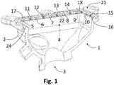
- an inventive exhaust gas cooler 1 comprises a substantially gas-tight housing 2 with an inlet 3, which allows the supply of a combustion exhaust gas emitted from an internal combustion engine.
- exhaust gas is to be interpreted in this context in a broad sense, and includes in particular any aerosol containing in addition to pure gas also solid or liquid suspended particles.
- dispersions which may comprise carbon dioxide, sulfur oxide, hydrochloric acid, nitrogen oxides, carbon monoxide, hydrocarbons, coal dust, particulate matter, soot, fly ash or volatile organic compounds (NMVOCs).
- the housing 2 consists for this purpose of a material which is suitable due to its material properties for sealing such exhaust gas against the ambient air.
- the pressure and heat resistance of the housing 2 are in particular due to the flow and heat energy generated in the context of a preceding combustion process and transported by means of the exhaust gas into the exhaust gas cooler 1.
- the housing 2 further has, downstream of the inlet 3, an outlet 4, through which the exhaust gas introduced into the exhaust gas cooler 1 can escape from the housing 2 after flowing through the exhaust gas cooler 1.
- the housing 2 is shaped such that the flow cross-section in the flow direction of the exhaust gas flowing through the exhaust gas 1 increases steadily.
- a component of this nature is called a diffuser in the construction of machinery, electricity, ventilators, vehicles, aircraft and ships.
- the expert in the field of fluid dynamics can calculate the opening angle of a suitable housing 2 of the exhaust gas cooler 1 according to the invention diffuser so that a separation of the exhaust gas flow from the inner wall of the housing 2 is largely avoided, so turbulence of the exhaust gas when flowing through the exhaust gas cooler 1 on a Minimum stay limited.
- the housing 2 in this case has a preferably completely circumferential support surface 16, which is the laying of a in Fig. 2 shown particulate filter 19, in particular a diesel particulate filter (DPF) or soot particulate filter (RPF), with a preferably completely encircling edge 22 allowed.
- a particle filter is to be understood as any device which permits a reduction of the particles in the flow of the exhaust gas which escapes through the outlet 4. Such particles may in particular comprise soot or hydrocarbons which could leave the internal combustion engine unburned due to the fuel properties and the combustion method used.
- the particulate filter 19 can be designed to be regenerative and allow self-cleaning, for example by means of controlled burn-off phases.
- the particle filter 19 may be a further filter element downstream of a regenerative filter and structurally separate from it.
- a filter element may serve, for example in the context of low-pressure exhaust gas recirculation, to protect the downstream exhaust gas turbocharger from larger particles which could become detached during cleaning of the primary, regenerative diesel particulate filter and jeopardize the functionality of the exhaust gas turbocharger.
- a substantially planar end surface 21 of the housing 2 Also in the region of the outlet 4 is a substantially planar end surface 21 of the housing 2.
- Wie Fig. 2 can recognize the end face 21 allows when pressed against the plane-parallel partial surface of a bottom group 20 (only in Fig. 2 shown) a positive connection of the exhaust gas cooler 1 with the bottom group 20.
- a suitable seal 23 in Fig. 1 not shown, which can be inserted into a, preferably completely circumferential, groove 24, and known connection techniques, the thus formed exhaust gas cooler 1 can connect largely gas-tight with a vehicle body.
- the bearing surface 16 is provided with a multiplicity of axial rib-shaped fastening elements 5-10.
- Fig. 1 suggests, frame these axial Fasteners 5-10 the diffuser along the outlet 4 in an approximately equidistant arrangement.
- a circumferential frame 17 is formed on the diffuser in the region of the outlet 4, which due to their profile - as in Fig. 2 shown - can serve as an enclosure of the resting on the support surface 16 particulate filter 19.
- the standing in this position with the particulate filter 19 in contact inner surface 18 nestles thereby approximately at right angles to the enclosed by its support surface 16 of the diffuser and has - each approximately equally spaced between two adjacent axial fastening elements 5, 6; 6, 7; 7, 8 - a plurality of additional, radial fastening elements 11-15.
- the latter like their axial counterparts, are designed to be elastic, but by virtue of their position pivoted by an angle of 90 ° they exert a bias which acts approximately in the direction of the center of the outlet 4.
- the one in the position according to Fig. 2 Particulate filter 19 is thus held non-positively by diametrically arranged pairs of radial fasteners 11-15 in just this position within the frame 17.
- the pliers 17 simultaneously forms a circumferential boundary wall of the aforementioned groove 24 for receiving the seal 23rd
Landscapes
- Engineering & Computer Science (AREA)
- Chemical & Material Sciences (AREA)
- Combustion & Propulsion (AREA)
- Mechanical Engineering (AREA)
- General Engineering & Computer Science (AREA)
- Chemical Kinetics & Catalysis (AREA)
- Exhaust Gas After Treatment (AREA)
- Exhaust-Gas Circulating Devices (AREA)
- Processes For Solid Components From Exhaust (AREA)
Description
- Die vorliegende Erfindung betrifft einen Abgaskühler für eine Verbrennungskraftmaschine, insbesondere für einen Verbrennungsmotor, mit den Merkmalen des Oberbegriffs des Anspruchs 1.
- Bei der Verbrennung von Kraftstoff in Ottomotoren, Dieselmotoren, Gasturbinen, Heizkesseln und anderen Verbrennungskraftmaschinen entstehen Stickoxide, deren Freisetzung in die Atmosphäre die Umwelt belasten kann. Der Stand der Technik umfasst jedoch Verbrennungskraftmaschinen, die sich durch eine verminderte Schadstoffemission auszeichnen. Einige solche Verbrennungskraftmaschinen bedienen sich zu diesem Zweck einer als Abgasrückführung (AGR) bekannten Technik.
-
EP 2 273 095 A1 beschreibt ein derartiges Abgasrückführsystem. Dabei wird der für den Verbrennungsvorgang benötigten Luft ein gewisser Anteil an Abgas hinzugemischt, sodass ein Gasgemisch mit einer gegenüber Reinluft verminderten Sauerstoffkonzentration entsteht. Dieses Gasgemisch wird seinerseits im Brennraum der Verbrennungskraftmaschine in herkömmlicher Weise mit Kraftstoff vermengt, dessen Kohlenwasserstoff-Moleküle im Rahmen der Verbrennung mittels des verbleibenden Luftsauerstoffs oxidiert werden. Bei diesem Prozess erweist sich das Abgas als chemisch inert, sodass nicht jedes Kraftstoffmolekül auf ein als Reaktionspartner geeignetes Sauerstoffmolekül trifft. Die derart behinderte Oxidation von Kraftstoffmolekülen zieht eine insgesamt langsamere Verbrennung des Kraftstoffs nach sich, sodass Temperaturspitzen im Brennraum weitgehend vermieden werden. Da von der Verbrennungstemperatur wiederum die Reaktionsgeschwindigkeit der Stickoxidbildung abhängt, weist eine so konfigurierte Verbrennungskraftmaschine einen verringerten Schadstoffausstoß auf. Der beschriebene Zusammenhang ist in der Chemie als Zeldovich-Mechanismus oder thermischer NO-Mechanismus bekannt. - Die durch die Abgasrückführung erzielte Wirkung lässt sich in bekannter Weise verstärken, indem das verwendete Abgas, dessen originäre Temperatur bis zu 400 °C betragen kann, vor der Rückführung in den Brennraum abgekühlt wird.
EP 2 194 351 B1 beschreibt in diesem Kontext einen Abgaskühler mit einer Mehrzahl von Abgas führenden, zumindest teilweise als Tauscherrohren ausgebildeten Strömungskanälen. Während das Abgas einen solchen Kühler in wechselnder Richtung durchströmt, wird es mittels eines geeigneten, mit den Kanälen in thermischem Austausch stehenden Fluids fortwährend gekühlt. - Handelt es sich bei der Verbrennungskraftmaschine um einen Kolbenmotor, insbesondere einen Dieselmotor, so umfasst dieser zum Zweck der Effizienz- oder Leistungssteigerung häufig zusätzlich einen Abgas-Turbolader (ATL), der seine Energie aus dem Restdruck des Abgases gewinnt. Das Abgas wird im Fall der sogenannten Niederdruck-Abgasrückführung der Verbrennungsluft des Motors dabei stromaufwärts des Abgas-Turboladers zugeführt. Bei dieser Anordnung können jedoch vom Abgasstrom mitgeführte Partikel den Abgas-Turbolader beschädigen. Aus diesem Grund wurde etwa in
WO 2012/045673 vorgeschlagen, stromabwärts des Abgaskühlers einen geeigneten Partikelfilter vorzusehen.WO 2007/079138 offenbart einen solchen Filter, der auf einem Drahtgeflecht mit einem Porendurchmesser zwischen 2 µm und 15 µm basiert. - Problematisch ist dabei vor allem das Befestigungskonzept der bekannten Filter insbesondere im Rahmen einer Serienfertigung. Insofern können unvermeidbare Toleranzen des Filters sowie anderer Bauteile im Betrieb der Verbrennungskraftmaschine dazu führen, dass auf den Filter wirkende Vibrationen diesen aus seiner vorgesehenen Position lösen. Bei den bekannten Ansätzen wird der Filter daher zur Fixierung mit dem Abgaskühler zumeist mittels konventioneller Schweiß- oder Löttechniken verbunden. Die hierzu verwendeten Werkzeuge verursachen jedoch hohe Anschaffungs- und Betriebskosten, die sich negativ auf die Stückkosten entsprechend gefertigter Abgaskühler auswirken.
- Ein gattungsgemäßer Abgaskühler ist aus der
WO 88/03049 A1 - Aus der
JP S63-85211 A - Die vorliegende Erfindung beschäftigt sich mit dem Problem, für einen Abgaskühler eine verbesserte Ausführungsform anzugeben, die sich insbesondere durch eine unkomplizierte Befestigungsmöglichkeit für einen Partikelfilter auszeichnet.
- Dieses Problem wird erfindungsgemäß durch den Gegenstand des unabhängigen Anspruchs gelöst. Vorteilhafte Ausführungsformen sind Gegenstand der abhängigen Ansprüche.
- Die Erfindung beruht auf dem allgemeinen Gedanken, das Gehäuse des Abgaskühlers selbst im Bereich des Auslasses mit Mitteln zum Befestigen eines Partikelfilters zu versehen. Zeit- und kostenintensive Fügeverbindungen wie Schweißen oder Löten, die eine starke Wärme- oder Druckeinwirkung auf den Partikelfilter oder den Abgaskühler zumindest entlang eines Flansches sowie den Einsatz geeigneter Zusatzwerkstoffe erfordern, werden bei diesem Ansatz entbehrlich.
- Erfindungsgemäß ist der Abgaskühler zumindest bereichsweise in Form eines Diffusors ausgebildet, dessen Strömungsquerschnitt in Richtung des Auslasses, also stromabwärts, im Wesentlichen zunimmt. Auf diese Weise lässt sich die Strömung des den Kühler durchlaufenden Abgases verlangsamen. Mittels der so herbeigeführten Verzögerung wird ein Teil der kinetischen Energie des in den Kühler einströmenden Abgases gleichsam in Druckenergie gewandelt, um den Gasdruck zu erhöhen. Der Diffusor lässt sich dabei mit einer den Auslass zumindest bereichsweise umlaufenden Auflagefläche versehen, die ein Auflegen des Partikelfilters, insbesondere in einem Randbereich, auf den Diffusor zum Zweck der Befestigung erlaubt.
- Erfindungsgemäß lässt sich die genannte Auflagefläche des Diffusors zur Anbringung axialer Befestigungselemente nutzen, die durch eine solche Anordnung unmittelbar mechanisch oder magnetisch auf den Partikelfilter wirken können, wenn dieser auf der Auflagefläche ruht.
- Gemäß einer anderen vorteilhaften Ausführungsform weist das Gehäuse im Bereich des besagten Auslasses zudem eine Abschlussfläche auf, die aufgrund ihrer Gestaltung eine formschlüssige Verbindung der Abschlussfläche mit einer Bodengruppe erlaubt. Eine derart geformte Abschlussfläche ermöglicht es etwa, den Abgaskühler an einer selbsttragenden Karosserie zu befestigen. Im Rahmen des Automobilbaus kann ein in der genannten Weise montierter Abgaskühler mit einem von dem Fahrzeugaufbau getragenen Verbrennungsmotor gekoppelt und insbesondere in dessen Abgasrückführung integriert werden. Aufgrund des hergestellten Formschlusses wirkt die Schwerkraft im betriebsbereiten Zustand des Fahrzeugs dabei normal, also rechtwinklig auf die Abschlussfläche, die beispielsweise mittels bekannter stiftartiger Verbindungselemente wie Nieten oder Schrauben an der Bodengruppe fixiert werden kann.
- Vorzugsweise ist das axiale Befestigungselement elastisch ausgeführt und auf der Auflagefläche dergestalt angeordnet, dass - im mit der Bodengruppe verbundenen Zustand des Abgaskühlers - das axiale Befestigungselement eine Vorspannung auf den Partikelfilter in Richtung der Bodengruppe auszuüben vermag, wenn dieser auf der Auflagefläche aufliegt. Etwaige Höhenunterschiede und andere Toleranzen von Diffusor und Bodengruppe in axialer Richtung werden durch die Elastizität des axialen Befestigungselements in dieser Anordnung potenziell kompensiert. Selbst im Fall von Vibrationen, wie sie im Fahrbetrieb des mit einem erfindungsgemäßen Abgaskühler versehenen Kraftfahrzeugs auftreten können, fixiert das Befestigungselement den Partikelfilter somit und verhindert dessen Loslösen vom Diffusor.
- Des Weiteren weist der Diffusor erfindungsgemäß eine den Auslass zumindest bereichsweise umlaufende Zarge auf, die den Partikelfilter seitlich einfasst, wenn dieser auf der Auflagefläche ruht. Auf diese Weise besteht im montierten Zustand des Abgaskühlers nicht nur in dessen axialer Richtung ein Formschluss, der zur Fixation des Partikelfilters beiträgt; vielmehr ist der Partikelfilter auch in radialer Richtung gegen ein seitliches Verrutschen geschützt. Die beschriebene Funktion der Zarge lässt sich mittels eines weiteren, radialen Befestigungselements realisieren, welches auf einer der Auflagefläche benachbarten Innenfläche der Zarge angeordnet ist. Vorteilhaft ist dabei eine im Wesentlichen rechtwinklige Anordnung von Auflage- und Innenfläche, die eine gleichmäßige Krafteinwirkung auf beide Flächen gewährleistet.
- Es empfiehlt sich in diesem Fall auch hinsichtlich des radialen Befestigungselements eine elastische Ausgestaltung, sodass das radiale Befestigungselement eine Vorspannung in zentrischer Richtung auf den auf die Auflagefläche aufgelegten Partikelfilter ausüben kann. Ein derartiges Verspannen des Partikelfilters innerhalb der Zarge gestattet eine flexible Handhabung des Abgaskühlers im Rahmen des Montagevorgangs, ohne ein Herausfallen des Filters aus seiner Einfassung zu riskieren.
- Die besagte Haltewirkung lässt sich vorzugsweise mittels einer Vielzahl sowohl axialer als auch radialer Befestigungselemente erzielen, die den Auslass umlaufend auf der Auflage- und Innenfläche angeordnet sind. Vorteilhaft ist insbesondere eine alternierende Anordnung, bei der axiale und radiale Befestigungselemente entlang des von Zarge und Auflagefläche gebildeten Randes des Auslasses abwechselnd aufeinander folgen. Eine solche Konfiguration begünstigt eine Wechselwirkung gegenüber liegender und benachbarter Befestigungselemente, die im montierten Zustand des Abgaskühlers ein Verrutschen des Partikelfilters zuverlässig unterbindet.
- Weitere wichtige Merkmale und Vorteile der Erfindung ergeben sich aus den Unteransprüchen, aus den Zeichnungen und aus der zugehörigen Figurenbeschreibung anhand der Zeichnungen.
- Es versteht sich, dass die vorstehend genannten und die nachstehend noch zu erläuternden Merkmale nicht nur in der jeweils angegebenen Kombination, sondern auch in anderen Kombinationen oder in Alleinstellung verwendbar sind, ohne den Rahmen der vorliegenden Erfindung zu verlassen.
- Bevorzugte Ausführungsbeispiele der Erfindung sind in den Zeichnungen dargestellt und werden in der nachfolgenden Beschreibung näher erläutert.
-
Figur 1 zeigt einen erfindungsgemäßen Abgaskühler in einer räumlichen Schnittdarstellung. -
Figur 2 zeigt in einer weiteren Schnittdarstellung den an einer Bodengruppe befestigten Abgaskühler gemäßFigur 1 in Verbindung mit einem Partikelfilter. - Entsprechend
Fig. 1 umfasst ein erfindungsgemäßer Abgaskühler 1 ein weitgehend gasdichtes Gehäuse 2 mit einem Einlass 3, welcher die Zuführung eines von einer Verbrennungskraftmaschine ausgestoßenen Verbrennungsabgases erlaubt. Der Begriff "Abgas" ist in diesem Zusammenhang in einem weiten Wortsinn auszulegen und umfasst insbesondere jegliches Aerosol, das neben reinem Gas auch feste oder flüssige Schwebeteilchen enthält. In Betracht kommen etwa Dispersionen, die Kohlenstoffdioxid, Schwefeloxid, Salzsäure, Stickstoffoxide, Kohlenstoffmonoxid, Kohlenwasserstoffe, Kohlenstaub, Feinstaub, Ruß, Flugasche oder flüchtige organische Verbindungen (NMVOC) umfassen können. - Das Gehäuse 2 besteht zu diesem Zweck aus einem Werkstoff, der aufgrund seiner Materialeigenschaften zur Abdichtung derartigen Abgases gegen die Umgebungsluft geeignet ist. Die Druck- und Hitzebeständigkeit des Gehäuses 2 sind insbesondere bedingt durch die Strömungs- und Wärmeenergie, die im Rahmen eines vorangehenden Verbrennungsvorgangs erzeugt und mittels des Abgases in den Abgaskühler 1 transportiert wird. Das Gehäuse 2 weist ferner stromabwärts des Einlasses 3 einen Auslass 4 auf, durch welchen das in den Abgaskühler 1 eingeleitete Abgas nach dem Durchströmen des Abgaskühlers 1 aus dem Gehäuse 2 entweichen kann.
- Zwischen dem Einlass 3 und dem Auslass 4 ist das Gehäuse 2 derart geformt, dass der Durchflussquerschnitt in Fließrichtung des den Abgaskühler 1 durchströmenden Abgases stetig zunimmt. Ein so beschaffenes Bauteil wird im Maschinen-, Elektrizitätswerks-, Ventilator-, Fahrzeug-, Flugzeug- und Schiffbau als Diffusor bezeichnet. Der Fachmann auf dem Gebiet der Strömungslehre vermag den Öffnungswinkel eines als Gehäuse 2 des erfindungsgemäßen Abgaskühlers 1 geeigneten Diffusors so zu berechnen, dass ein Ablösen der Abgasströmung von der Innenwand des Gehäuses 2 weitgehend vermieden wird, sodass Verwirbelungen des Abgases beim Durchströmen des Abgaskühlers 1 auf ein Mindestmaß beschränkt bleiben.
- Im Bereich des Auslasses 4 weist das Gehäuse 2 dabei eine vorzugsweise vollständig umlaufende Auflagefläche 16 auf, die das Auflegen eines in
Fig. 2 gezeigten Partikelfilters 19, insbesondere eines Dieselpartikelfilters (DPF) oder Rußpartikelfilters (RPF), mit einem vorzugsweise vollständig umlaufenden Rand 22, erlaubt. Als Partikelfilter ist im vorliegenden Kontext jede Einrichtung zu verstehen, die eine Reduzierung der Partikel im Strom des durch den Auslass 4 entweichenden Abgases erlaubt. Derartige Partikel können insbesondere Ruß oder Kohlenwasserstoffe umfassen, die die Verbrennungskraftmaschine aufgrund der Kraftstoffeigenschaften und des angewandten Verbrennungsverfahrens unverbrannt verlassen konnten. Der Partikelfilter 19 kann dabei regenerativ ausgelegt sein und eine Selbstreinigung etwa mittels kontrolliert ausgelöster Abbrandphasen erlauben. Ebenso kann es sich bei dem Partikelfilter 19 um ein weiteres, einem regenerativen Filter nachgelagertes und von diesem baulich getrenntes Filterglied handeln. Ein solches Filterglied mag etwa im Rahmen einer Niederdruck-Abgasrückführung dazu dienen, den stromabwärts angeordneten Abgas-Turbolader vor größeren Partikeln zu schützen, die sich bei der Reinigung des primären, regenerativen Dieselrußpartikelfilters aus selbigem lösen und die Funktionsfähigkeit des Abgas-Turboladers gefährden könnten. - Ebenfalls im Bereich des Auslasses 4 befindet sich eine im Wesentlichen plane Abschlussfläche 21 des Gehäuses 2. Wie
Fig. 2 erkennen lässt, ermöglicht die Abschlussfläche 21 beim Anpressen an die planparallele Teilfläche einer Bodengruppe 20 (nur inFig. 2 gezeigt) eine formschlüssige Verbindung des Abgaskühlers 1 mit der Bodengruppe 20. Mittels einer geeigneten Dichtung 23 (inFig. 1 nicht gezeigt), die in eine, vorzugsweise vollständig umlaufende, Nut 24 einlegbar ist, und bekannter Verbindungstechniken lässt sich der so geformte Abgaskühler 1 weitgehend gasdicht mit einem Fahrzeugaufbau verbinden. - Um in dieser Konstellation den auf die Auflagefläche 16 aufgelegten Partikelfilter 19 zwischen dem Auslass 4 und der Bodengruppe 20 stabil zu lagern und gleichzeitig etwaige Fertigungstoleranzen der den Partikelfilter 19 umgebenden Bauteile auszugleichen, ist die Auflagefläche 16 mit einer Vielzahl axialer rippenförmiger Befestigungselemente 5-10 versehen. Wie
Fig. 1 andeutet, umrahmen diese axialen Befestigungselemente 5-10 den Diffusor entlang des Auslasses 4 in einer näherungsweise äquidistanten Anordnung. - Darüber hinaus ist an den Diffusor im Bereich des Auslasses 4 eine diesen umlaufende Zarge 17 angeformt, die aufgrund ihres Profils - wie in
Fig. 2 gezeigt - als Einfassung des auf der Auflagefläche 16 ruhenden Partikelfilters 19 dienen kann. Die in dieser Position mit dem Partikelfilter 19 in Kontakt stehende Innenfläche 18 schmiegt sich dabei etwa rechtwinklig an die von ihr eingeschlossene Auflagefläche 16 des Diffusors an und weist - jeweils ungefähr gleichmäßig beabstandet zwischen zwei benachbarten axialen Befestigungselementen 5, 6; 6, 7; 7, 8 - eine Vielzahl zusätzlicher, radialer Befestigungselemente 11-15 auf. Letztere sind ebenso wie ihre axialen Gegenstücke elastisch ausgeführt, üben durch ihre um einen Winkel von 90° verschwenkte Position jedoch eine Vorspannung aus, die etwa in Richtung des Mittelpunkts des Auslasses 4 wirkt. Der in der Stellung gemäßFig. 2 befindliche Partikelfilter 19 wird somit durch diametral angeordnete Paare radialer Befestigungselemente 11-15 in eben dieser Position innerhalb der Zarge 17 kraftschlüssig festgehalten. - Die Zange 17 bildet gleichzeitig eine umlaufende Begrenzungswand der vorstehend genannten Nut 24 zur Aufnahme der Dichtung 23.
Claims (6)
- Abgaskühler (1) für eine Verbrennungskraftmaschine, insbesondere einen Verbrennungsmotor, mit- einem Gehäuse (2),- zumindest einem am Gehäuse (2) vorgesehenen Einlass (3) zum Zuführen von Abgas,- zumindest einem am Gehäuse (2) vorgesehenen Auslass (4) zum Abführen von Abgas, wobei der Einlass (3) und der Auslass (4) innerhalb des Gehäuses (2) fluidisch verbunden sind,- wobei das Gehäuse (2) Befestigungselemente (5-15) zum Befestigen eines Partikelfilters (19) im Bereich des Auslasses (4) aufweist,- wobei das Gehäuse (2) zumindest bereichsweise in Form eines Diffusors ausgebildet ist, dessen Strömungsquerschnitt in Richtung des Auslasses (4) im Wesentlichen zunimmt,- wobei der Diffusor eine den Auslass (4) zumindest bereichsweise umlaufende Auflagefläche (16) zum Auflegen des Partikelfilters (19) aufweist,dadurch gekennzeichnet,- dass die Befestigungselemente (5-15) mehrere axiale Befestigungselemente (5-10) umfassen, die auf der Auflagefläche (16) angeordnet sind,- dass der Diffusor ferner eine den Auslass (4) zumindest bereichsweise umlaufende Zarge (17) zum Einfassen des Partikelfilters (19) aufweist,- dass die Befestigungselemente (5-15) mehrere radiale Befestigungselemente (11-15) umfassen, die auf einer der Auflagefläche (16) benachbarten Innenfläche (18) der Zarge (17) angeordnet sind.
- Abgaskühler (1) nach Anspruch 1,
dadurch gekennzeichnet,
dass das Gehäuse (2) im Bereich des Auslasses (4) ferner eine Abschlussfläche (21) aufweist, so gestaltet, dass der Abgaskühler (1) entlang der Abschlussfläche (21) mit einer Bodengruppe (20) formschlüssig verbunden werden kann. - Abgaskühler (1) nach Anspruch 2,
dadurch gekennzeichnet,
dass die axialen Befestigungselemente (5-10) elastisch ausgeführt und so auf der Auflagefläche (16) angeordnet sind, dass die axialen Befestigungselemente (5-10) den auf die Auflagefläche (16) aufgelegten Partikelfilter (19) in Richtung der Bodengruppe (20) vorspannen, wenn der Abgaskühler (1) mit der Bodengruppe (20) verbunden wird. - Abgaskühler (1) nach einem der Ansprüche 1 bis 3,
dadurch gekennzeichnet,
dass die Auflagefläche (16) und die Innenfläche (18) im Wesentlichen rechtwinklig angeordnet sind. - Abgaskühler (1) nach Anspruch 4,
dadurch gekennzeichnet,
dass die radialen Befestigungselemente (11-15) elastisch ausgeführt und so auf der Innenfläche (18) angeordnet sind, dass die radialen Befestigungselemente (11-15) den auf die Auflagefläche (16) aufgelegten Partikelfilter (19) innerhalb der Zarge (17) verspannen. - Abgaskühler (1) nach Anspruch 5,
dadurch gekennzeichnet,
dass die axialen Befestigungselemente (5-10) und die radialen Befestigungselemente (11-15)den Auslass (4) in einer im Wesentlichen alternierenden Abfolge umlaufen.
Applications Claiming Priority (1)
| Application Number | Priority Date | Filing Date | Title |
|---|---|---|---|
| DE102013208436.6A DE102013208436A1 (de) | 2013-05-08 | 2013-05-08 | Abgaskühler |
Publications (2)
| Publication Number | Publication Date |
|---|---|
| EP2801709A1 EP2801709A1 (de) | 2014-11-12 |
| EP2801709B1 true EP2801709B1 (de) | 2017-06-14 |
Family
ID=50473193
Family Applications (1)
| Application Number | Title | Priority Date | Filing Date |
|---|---|---|---|
| EP14164458.3A Not-in-force EP2801709B1 (de) | 2013-05-08 | 2014-04-11 | Abgaskühler |
Country Status (3)
| Country | Link |
|---|---|
| EP (1) | EP2801709B1 (de) |
| KR (1) | KR102133831B1 (de) |
| DE (1) | DE102013208436A1 (de) |
Families Citing this family (2)
| Publication number | Priority date | Publication date | Assignee | Title |
|---|---|---|---|---|
| ES2531124B1 (es) * | 2013-09-10 | 2016-01-22 | Valeo Térmico, S. A. | Intercambiador de calor para gases, en especial de los gases de escape de un motor |
| ES2618883B1 (es) * | 2015-12-21 | 2018-01-31 | Valeo Térmico, S. A. | Conjunto de unidad de conducción de gases y filtro de partículas, método de fabricación del mismo e intercambiador de calor para gases, en especial de los gases de escape de un motor |
Family Cites Families (16)
| Publication number | Priority date | Publication date | Assignee | Title |
|---|---|---|---|---|
| JPS6385211A (ja) * | 1986-09-26 | 1988-04-15 | Nippon Denso Co Ltd | 排気ガス浄化装置 |
| CA1315668C (en) * | 1986-10-31 | 1993-04-06 | Ewald Wilhelm Simmerlein-Erlbacher | Filter-device and a filter-appliance from such filter-device |
| US5431706A (en) * | 1993-10-05 | 1995-07-11 | Dry Systems Technologies | Disposable particulate filter |
| US5785030A (en) * | 1996-12-17 | 1998-07-28 | Dry Systems Technologies | Exhaust gas recirculation in internal combustion engines |
| KR20060058330A (ko) * | 2004-11-25 | 2006-05-30 | 현대자동차주식회사 | 촉매 필터가 구비된 이지알 쿨러 |
| KR200409400Y1 (ko) * | 2005-11-22 | 2006-02-22 | 주식회사 두원공조 | 열교환기와 팬 쉬라우드의 결합구조 |
| US7980068B2 (en) | 2005-12-29 | 2011-07-19 | Tenneco Automotive Operating Company Inc. | Woven metal fiber particulate filter |
| US7788913B2 (en) * | 2006-02-16 | 2010-09-07 | Indmar Products Company Inc. | Manifold mounted catalytic converter |
| WO2009076342A2 (en) * | 2007-12-11 | 2009-06-18 | Borgwarner Inc. | Module integrating various combinations of an exhaust air cooler, valve, throttle valve, mixer and particle separator into a common housing |
| FR2925351B1 (fr) * | 2007-12-20 | 2010-11-05 | Valeo Systemes Thermiques | Module de filtrage de produits de condensation pour echangeur de chaleur et ensemble forme par un echangeur de chaleur et son module de filtrage. |
| FR2930278A1 (fr) * | 2008-04-18 | 2009-10-23 | Renault Sas | Module de recirculation des gaz d'echappement |
| EP2194351B1 (de) | 2008-12-03 | 2012-05-02 | Behr GmbH & Co. KG | Abgaskühler mit integrierten Partikelfilter für einen Verbrennungsmotor |
| EP2273095B1 (de) | 2009-07-10 | 2014-01-08 | Behr GmbH & Co. KG | Wärmetauscher, Abgasrückführsystem und Brennkraftmaschine |
| KR20110056137A (ko) * | 2009-11-20 | 2011-05-26 | 주식회사 알란텀 | Egr 가스 필터 시스템 |
| JP5263191B2 (ja) * | 2010-02-01 | 2013-08-14 | 三菱自動車工業株式会社 | 内燃機関の流体濾過冷却装置 |
| DE102010041982A1 (de) | 2010-10-05 | 2012-04-05 | Mahle International Gmbh | Abgasrückführfilter, Brennkraftmaschine |
-
2013
- 2013-05-08 DE DE102013208436.6A patent/DE102013208436A1/de not_active Withdrawn
-
2014
- 2014-04-11 EP EP14164458.3A patent/EP2801709B1/de not_active Not-in-force
- 2014-04-22 KR KR1020140048033A patent/KR102133831B1/ko not_active Expired - Fee Related
Also Published As
| Publication number | Publication date |
|---|---|
| EP2801709A1 (de) | 2014-11-12 |
| KR20140132672A (ko) | 2014-11-18 |
| DE102013208436A1 (de) | 2014-11-13 |
| KR102133831B1 (ko) | 2020-07-15 |
Similar Documents
| Publication | Publication Date | Title |
|---|---|---|
| DE102013012336B4 (de) | Nachbehandlungssystem | |
| EP2273095B1 (de) | Wärmetauscher, Abgasrückführsystem und Brennkraftmaschine | |
| DE112009001059T5 (de) | Durch Abgas angetriebene Hilfsluftpumpe und Produkte und Verfahren zu ihrer Verwendung | |
| DE112010001696T5 (de) | Verfahren zum verbessern des anspring- oder regenerierungsverhaltenseiner nachbehandlungseinrichtung in einem fahrzeugsystem | |
| EP1728984A2 (de) | Abgasanlage | |
| DE112007002746B4 (de) | Verfahren zum Versorgen eines Motors mit Auspuffgas, Auspuffelement, Auspuffanlage und Fahrzeug umfassend Mittel zum Versorgen eines solchen Motors mit Auspuffgas | |
| DE102015107083A1 (de) | Externe Strömungskammern zur Abgasführung für eine Mehrfachkatalysatorarchitektur | |
| WO2013127924A2 (de) | Gasturbinenanlage mit abgasrezirkulation | |
| DE102006049005B4 (de) | Fluidmitnahmevorrichtung sowie damit ausgestattetes Abgassystem | |
| DE102017100217A1 (de) | Motorabgasrückführungsanlage mit wenigstens einer abgasrückführungsbehandlungseinrichtung | |
| DE112011101624T5 (de) | Gerät und System zum Zurückhalten von Bruchstücken und Abfangen von Funken | |
| DE112010003888T5 (de) | Abgasrückführungssystem und Abgasrückführungsvorrichtung für einen gleichstromgespülten Zweitakt-Dieselmotor für eine Lokomotive | |
| DE102014002892A1 (de) | System und Verfahren zum Aufnehmen von Nachbehandlungsblöcken | |
| DE102008057895A1 (de) | Abgasreinigungsvorrichtung für Verbrennungsmotor | |
| DE102011085800A1 (de) | Filter zum Einsetzen in eine fluidführende Rohrleitung | |
| EP2314838B1 (de) | Vorrichtung zur Kühlung eines aus einem Rußpartikelfilter austretenden Abgasstroms | |
| EP2801709A1 (de) | Abgaskühler | |
| DE102013019763A1 (de) | System und Verfahren zum Halten von Nachbehandlungsträgern | |
| DE112021006531T5 (de) | Turbine | |
| DE102013015602A1 (de) | Abgasnachbehandlungssystem für eine Brennkraftmaschine und Brennkraftmaschine | |
| DE102017118214A1 (de) | Abgasnachbehandlungssystem sowie Verfahren zur Abgasnachbehandlung eines Verbrennungsmotors | |
| DE102017205696B4 (de) | Abgasnachbehandlungssystem für einen Verbrennungsmotor sowie Verbrennungsmotor | |
| EP3181851A1 (de) | Filter zum entfernen von partikeln aus einem fluidstrom in einer fluidleitung einer brennkraftmaschine | |
| AT516467A1 (de) | Katalysatoreinrichtung für eine stationäre Brennkraftmaschine | |
| DE102014003390B4 (de) | Antriebseinrichtung |
Legal Events
| Date | Code | Title | Description |
|---|---|---|---|
| PUAI | Public reference made under article 153(3) epc to a published international application that has entered the european phase |
Free format text: ORIGINAL CODE: 0009012 |
|
| 17P | Request for examination filed |
Effective date: 20140411 |
|
| AK | Designated contracting states |
Kind code of ref document: A1 Designated state(s): AL AT BE BG CH CY CZ DE DK EE ES FI FR GB GR HR HU IE IS IT LI LT LU LV MC MK MT NL NO PL PT RO RS SE SI SK SM TR |
|
| AX | Request for extension of the european patent |
Extension state: BA ME |
|
| R17P | Request for examination filed (corrected) |
Effective date: 20150512 |
|
| RBV | Designated contracting states (corrected) |
Designated state(s): AL AT BE BG CH CY CZ DE DK EE ES FI FR GB GR HR HU IE IS IT LI LT LU LV MC MK MT NL NO PL PT RO RS SE SI SK SM TR |
|
| 17Q | First examination report despatched |
Effective date: 20151022 |
|
| RIC1 | Information provided on ipc code assigned before grant |
Ipc: F28D 21/00 20060101ALI20161117BHEP Ipc: F28F 19/01 20060101ALI20161117BHEP Ipc: F02M 26/12 20160101ALI20161117BHEP Ipc: F28F 9/02 20060101ALN20161117BHEP Ipc: F02M 26/15 20160101ALI20161117BHEP Ipc: F02M 26/35 20160101ALI20161117BHEP Ipc: F01N 3/021 20060101AFI20161117BHEP Ipc: F02M 26/30 20160101ALI20161117BHEP Ipc: F01N 13/18 20100101ALI20161117BHEP |
|
| GRAP | Despatch of communication of intention to grant a patent |
Free format text: ORIGINAL CODE: EPIDOSNIGR1 |
|
| INTG | Intention to grant announced |
Effective date: 20170102 |
|
| GRAS | Grant fee paid |
Free format text: ORIGINAL CODE: EPIDOSNIGR3 |
|
| GRAA | (expected) grant |
Free format text: ORIGINAL CODE: 0009210 |
|
| AK | Designated contracting states |
Kind code of ref document: B1 Designated state(s): AL AT BE BG CH CY CZ DE DK EE ES FI FR GB GR HR HU IE IS IT LI LT LU LV MC MK MT NL NO PL PT RO RS SE SI SK SM TR |
|
| REG | Reference to a national code |
Ref country code: GB Ref legal event code: FG4D Free format text: NOT ENGLISH |
|
| REG | Reference to a national code |
Ref country code: CH Ref legal event code: EP Ref country code: AT Ref legal event code: REF Ref document number: 901182 Country of ref document: AT Kind code of ref document: T Effective date: 20170615 |
|
| REG | Reference to a national code |
Ref country code: IE Ref legal event code: FG4D Free format text: LANGUAGE OF EP DOCUMENT: GERMAN |
|
| REG | Reference to a national code |
Ref country code: DE Ref legal event code: R096 Ref document number: 502014004160 Country of ref document: DE |
|
| REG | Reference to a national code |
Ref country code: NL Ref legal event code: MP Effective date: 20170614 |
|
| REG | Reference to a national code |
Ref country code: LT Ref legal event code: MG4D |
|
| PG25 | Lapsed in a contracting state [announced via postgrant information from national office to epo] |
Ref country code: FI Free format text: LAPSE BECAUSE OF FAILURE TO SUBMIT A TRANSLATION OF THE DESCRIPTION OR TO PAY THE FEE WITHIN THE PRESCRIBED TIME-LIMIT Effective date: 20170614 Ref country code: HR Free format text: LAPSE BECAUSE OF FAILURE TO SUBMIT A TRANSLATION OF THE DESCRIPTION OR TO PAY THE FEE WITHIN THE PRESCRIBED TIME-LIMIT Effective date: 20170614 Ref country code: NO Free format text: LAPSE BECAUSE OF FAILURE TO SUBMIT A TRANSLATION OF THE DESCRIPTION OR TO PAY THE FEE WITHIN THE PRESCRIBED TIME-LIMIT Effective date: 20170914 Ref country code: LT Free format text: LAPSE BECAUSE OF FAILURE TO SUBMIT A TRANSLATION OF THE DESCRIPTION OR TO PAY THE FEE WITHIN THE PRESCRIBED TIME-LIMIT Effective date: 20170614 Ref country code: GR Free format text: LAPSE BECAUSE OF FAILURE TO SUBMIT A TRANSLATION OF THE DESCRIPTION OR TO PAY THE FEE WITHIN THE PRESCRIBED TIME-LIMIT Effective date: 20170915 |
|
| PG25 | Lapsed in a contracting state [announced via postgrant information from national office to epo] |
Ref country code: LV Free format text: LAPSE BECAUSE OF FAILURE TO SUBMIT A TRANSLATION OF THE DESCRIPTION OR TO PAY THE FEE WITHIN THE PRESCRIBED TIME-LIMIT Effective date: 20170614 Ref country code: RS Free format text: LAPSE BECAUSE OF FAILURE TO SUBMIT A TRANSLATION OF THE DESCRIPTION OR TO PAY THE FEE WITHIN THE PRESCRIBED TIME-LIMIT Effective date: 20170614 Ref country code: SE Free format text: LAPSE BECAUSE OF FAILURE TO SUBMIT A TRANSLATION OF THE DESCRIPTION OR TO PAY THE FEE WITHIN THE PRESCRIBED TIME-LIMIT Effective date: 20170614 Ref country code: NL Free format text: LAPSE BECAUSE OF FAILURE TO SUBMIT A TRANSLATION OF THE DESCRIPTION OR TO PAY THE FEE WITHIN THE PRESCRIBED TIME-LIMIT Effective date: 20170614 Ref country code: BG Free format text: LAPSE BECAUSE OF FAILURE TO SUBMIT A TRANSLATION OF THE DESCRIPTION OR TO PAY THE FEE WITHIN THE PRESCRIBED TIME-LIMIT Effective date: 20170914 |
|
| PG25 | Lapsed in a contracting state [announced via postgrant information from national office to epo] |
Ref country code: SK Free format text: LAPSE BECAUSE OF FAILURE TO SUBMIT A TRANSLATION OF THE DESCRIPTION OR TO PAY THE FEE WITHIN THE PRESCRIBED TIME-LIMIT Effective date: 20170614 Ref country code: EE Free format text: LAPSE BECAUSE OF FAILURE TO SUBMIT A TRANSLATION OF THE DESCRIPTION OR TO PAY THE FEE WITHIN THE PRESCRIBED TIME-LIMIT Effective date: 20170614 Ref country code: RO Free format text: LAPSE BECAUSE OF FAILURE TO SUBMIT A TRANSLATION OF THE DESCRIPTION OR TO PAY THE FEE WITHIN THE PRESCRIBED TIME-LIMIT Effective date: 20170614 Ref country code: CZ Free format text: LAPSE BECAUSE OF FAILURE TO SUBMIT A TRANSLATION OF THE DESCRIPTION OR TO PAY THE FEE WITHIN THE PRESCRIBED TIME-LIMIT Effective date: 20170614 |
|
| PG25 | Lapsed in a contracting state [announced via postgrant information from national office to epo] |
Ref country code: ES Free format text: LAPSE BECAUSE OF FAILURE TO SUBMIT A TRANSLATION OF THE DESCRIPTION OR TO PAY THE FEE WITHIN THE PRESCRIBED TIME-LIMIT Effective date: 20170614 Ref country code: PL Free format text: LAPSE BECAUSE OF FAILURE TO SUBMIT A TRANSLATION OF THE DESCRIPTION OR TO PAY THE FEE WITHIN THE PRESCRIBED TIME-LIMIT Effective date: 20170614 Ref country code: IS Free format text: LAPSE BECAUSE OF FAILURE TO SUBMIT A TRANSLATION OF THE DESCRIPTION OR TO PAY THE FEE WITHIN THE PRESCRIBED TIME-LIMIT Effective date: 20171014 Ref country code: SM Free format text: LAPSE BECAUSE OF FAILURE TO SUBMIT A TRANSLATION OF THE DESCRIPTION OR TO PAY THE FEE WITHIN THE PRESCRIBED TIME-LIMIT Effective date: 20170614 Ref country code: IT Free format text: LAPSE BECAUSE OF FAILURE TO SUBMIT A TRANSLATION OF THE DESCRIPTION OR TO PAY THE FEE WITHIN THE PRESCRIBED TIME-LIMIT Effective date: 20170614 |
|
| REG | Reference to a national code |
Ref country code: DE Ref legal event code: R097 Ref document number: 502014004160 Country of ref document: DE |
|
| PLBE | No opposition filed within time limit |
Free format text: ORIGINAL CODE: 0009261 |
|
| STAA | Information on the status of an ep patent application or granted ep patent |
Free format text: STATUS: NO OPPOSITION FILED WITHIN TIME LIMIT |
|
| PG25 | Lapsed in a contracting state [announced via postgrant information from national office to epo] |
Ref country code: DK Free format text: LAPSE BECAUSE OF FAILURE TO SUBMIT A TRANSLATION OF THE DESCRIPTION OR TO PAY THE FEE WITHIN THE PRESCRIBED TIME-LIMIT Effective date: 20170614 |
|
| REG | Reference to a national code |
Ref country code: FR Ref legal event code: PLFP Year of fee payment: 5 |
|
| 26N | No opposition filed |
Effective date: 20180315 |
|
| PG25 | Lapsed in a contracting state [announced via postgrant information from national office to epo] |
Ref country code: SI Free format text: LAPSE BECAUSE OF FAILURE TO SUBMIT A TRANSLATION OF THE DESCRIPTION OR TO PAY THE FEE WITHIN THE PRESCRIBED TIME-LIMIT Effective date: 20170614 |
|
| PGFP | Annual fee paid to national office [announced via postgrant information from national office to epo] |
Ref country code: FR Payment date: 20180502 Year of fee payment: 5 |
|
| PG25 | Lapsed in a contracting state [announced via postgrant information from national office to epo] |
Ref country code: MT Free format text: LAPSE BECAUSE OF FAILURE TO SUBMIT A TRANSLATION OF THE DESCRIPTION OR TO PAY THE FEE WITHIN THE PRESCRIBED TIME-LIMIT Effective date: 20170614 |
|
| PG25 | Lapsed in a contracting state [announced via postgrant information from national office to epo] |
Ref country code: MC Free format text: LAPSE BECAUSE OF FAILURE TO SUBMIT A TRANSLATION OF THE DESCRIPTION OR TO PAY THE FEE WITHIN THE PRESCRIBED TIME-LIMIT Effective date: 20170614 |
|
| REG | Reference to a national code |
Ref country code: CH Ref legal event code: PL |
|
| REG | Reference to a national code |
Ref country code: BE Ref legal event code: MM Effective date: 20180430 |
|
| GBPC | Gb: european patent ceased through non-payment of renewal fee |
Effective date: 20180411 |
|
| REG | Reference to a national code |
Ref country code: IE Ref legal event code: MM4A |
|
| PG25 | Lapsed in a contracting state [announced via postgrant information from national office to epo] |
Ref country code: LU Free format text: LAPSE BECAUSE OF NON-PAYMENT OF DUE FEES Effective date: 20180411 |
|
| PG25 | Lapsed in a contracting state [announced via postgrant information from national office to epo] |
Ref country code: BE Free format text: LAPSE BECAUSE OF NON-PAYMENT OF DUE FEES Effective date: 20180430 Ref country code: CH Free format text: LAPSE BECAUSE OF NON-PAYMENT OF DUE FEES Effective date: 20180430 Ref country code: LI Free format text: LAPSE BECAUSE OF NON-PAYMENT OF DUE FEES Effective date: 20180430 Ref country code: GB Free format text: LAPSE BECAUSE OF NON-PAYMENT OF DUE FEES Effective date: 20180411 |
|
| PG25 | Lapsed in a contracting state [announced via postgrant information from national office to epo] |
Ref country code: IE Free format text: LAPSE BECAUSE OF NON-PAYMENT OF DUE FEES Effective date: 20180411 |
|
| PG25 | Lapsed in a contracting state [announced via postgrant information from national office to epo] |
Ref country code: TR Free format text: LAPSE BECAUSE OF FAILURE TO SUBMIT A TRANSLATION OF THE DESCRIPTION OR TO PAY THE FEE WITHIN THE PRESCRIBED TIME-LIMIT Effective date: 20170614 |
|
| PG25 | Lapsed in a contracting state [announced via postgrant information from national office to epo] |
Ref country code: HU Free format text: LAPSE BECAUSE OF FAILURE TO SUBMIT A TRANSLATION OF THE DESCRIPTION OR TO PAY THE FEE WITHIN THE PRESCRIBED TIME-LIMIT; INVALID AB INITIO Effective date: 20140411 Ref country code: PT Free format text: LAPSE BECAUSE OF FAILURE TO SUBMIT A TRANSLATION OF THE DESCRIPTION OR TO PAY THE FEE WITHIN THE PRESCRIBED TIME-LIMIT Effective date: 20170614 |
|
| PG25 | Lapsed in a contracting state [announced via postgrant information from national office to epo] |
Ref country code: MK Free format text: LAPSE BECAUSE OF NON-PAYMENT OF DUE FEES Effective date: 20170614 Ref country code: CY Free format text: LAPSE BECAUSE OF FAILURE TO SUBMIT A TRANSLATION OF THE DESCRIPTION OR TO PAY THE FEE WITHIN THE PRESCRIBED TIME-LIMIT Effective date: 20170614 Ref country code: FR Free format text: LAPSE BECAUSE OF NON-PAYMENT OF DUE FEES Effective date: 20190430 |
|
| PG25 | Lapsed in a contracting state [announced via postgrant information from national office to epo] |
Ref country code: AL Free format text: LAPSE BECAUSE OF FAILURE TO SUBMIT A TRANSLATION OF THE DESCRIPTION OR TO PAY THE FEE WITHIN THE PRESCRIBED TIME-LIMIT Effective date: 20170614 |
|
| REG | Reference to a national code |
Ref country code: AT Ref legal event code: MM01 Ref document number: 901182 Country of ref document: AT Kind code of ref document: T Effective date: 20190411 |
|
| PGFP | Annual fee paid to national office [announced via postgrant information from national office to epo] |
Ref country code: DE Payment date: 20200629 Year of fee payment: 7 |
|
| PG25 | Lapsed in a contracting state [announced via postgrant information from national office to epo] |
Ref country code: AT Free format text: LAPSE BECAUSE OF NON-PAYMENT OF DUE FEES Effective date: 20190411 |
|
| REG | Reference to a national code |
Ref country code: DE Ref legal event code: R119 Ref document number: 502014004160 Country of ref document: DE |
|
| PG25 | Lapsed in a contracting state [announced via postgrant information from national office to epo] |
Ref country code: DE Free format text: LAPSE BECAUSE OF NON-PAYMENT OF DUE FEES Effective date: 20211103 |