EP2801706B1 - Brennkraftmaschine, mit einem System zur variablen Betätigung der Einlassventile, welches ausgerüstet ist mit einem elektrischen 3-Wegeventil, welches mit 3 unterschiedlichen Stromstärken bestromt werden kann, und verfahren zur Steuerung dieser Brennkraftmaschine. - Google Patents
Brennkraftmaschine, mit einem System zur variablen Betätigung der Einlassventile, welches ausgerüstet ist mit einem elektrischen 3-Wegeventil, welches mit 3 unterschiedlichen Stromstärken bestromt werden kann, und verfahren zur Steuerung dieser Brennkraftmaschine. Download PDFInfo
- Publication number
- EP2801706B1 EP2801706B1 EP13167181.0A EP13167181A EP2801706B1 EP 2801706 B1 EP2801706 B1 EP 2801706B1 EP 13167181 A EP13167181 A EP 13167181A EP 2801706 B1 EP2801706 B1 EP 2801706B1
- Authority
- EP
- European Patent Office
- Prior art keywords
- valve
- intake
- engine
- tappet
- intake valves
- Prior art date
- Legal status (The legal status is an assumption and is not a legal conclusion. Google has not performed a legal analysis and makes no representation as to the accuracy of the status listed.)
- Active
Links
Images


Classifications
-
- F—MECHANICAL ENGINEERING; LIGHTING; HEATING; WEAPONS; BLASTING
- F01—MACHINES OR ENGINES IN GENERAL; ENGINE PLANTS IN GENERAL; STEAM ENGINES
- F01L—CYCLICALLY OPERATING VALVES FOR MACHINES OR ENGINES
- F01L13/00—Modifications of valve-gear to facilitate reversing, braking, starting, changing compression ratio, or other specific operations
- F01L13/0015—Modifications of valve-gear to facilitate reversing, braking, starting, changing compression ratio, or other specific operations for optimising engine performances by modifying valve lift according to various working parameters, e.g. rotational speed, load, torque
-
- F—MECHANICAL ENGINEERING; LIGHTING; HEATING; WEAPONS; BLASTING
- F01—MACHINES OR ENGINES IN GENERAL; ENGINE PLANTS IN GENERAL; STEAM ENGINES
- F01L—CYCLICALLY OPERATING VALVES FOR MACHINES OR ENGINES
- F01L13/00—Modifications of valve-gear to facilitate reversing, braking, starting, changing compression ratio, or other specific operations
- F01L13/0005—Deactivating valves
-
- F—MECHANICAL ENGINEERING; LIGHTING; HEATING; WEAPONS; BLASTING
- F01—MACHINES OR ENGINES IN GENERAL; ENGINE PLANTS IN GENERAL; STEAM ENGINES
- F01L—CYCLICALLY OPERATING VALVES FOR MACHINES OR ENGINES
- F01L9/00—Valve-gear or valve arrangements actuated non-mechanically
- F01L9/10—Valve-gear or valve arrangements actuated non-mechanically by fluid means, e.g. hydraulic
- F01L9/11—Valve-gear or valve arrangements actuated non-mechanically by fluid means, e.g. hydraulic in which the action of a cam is being transmitted to a valve by a liquid column
- F01L9/12—Valve-gear or valve arrangements actuated non-mechanically by fluid means, e.g. hydraulic in which the action of a cam is being transmitted to a valve by a liquid column with a liquid chamber between a piston actuated by a cam and a piston acting on a valve stem
- F01L9/14—Valve-gear or valve arrangements actuated non-mechanically by fluid means, e.g. hydraulic in which the action of a cam is being transmitted to a valve by a liquid column with a liquid chamber between a piston actuated by a cam and a piston acting on a valve stem the volume of the chamber being variable, e.g. for varying the lift or the timing of a valve
Definitions
- the present invention relates to internal-combustion engines of the type comprising, for each cylinder:
- the present applicant has been developing for some time internal-combustion engines comprising a system for variable actuation of the intake valves of the type indicated above, marketed under the trade name "Multiair".
- the present applicant is the holder of numerous patents and patent applications regarding engines provided with a system of the type specified above.
- Figure 1 of the annexed drawings shows a cross-sectional view of an engine provided with the "Multiair" system, as described in the European patent No. EP 0 803 642 B1 .
- the engine illustrated therein is a multicylinder engine, for example an inline-four-cylinder engine, comprising a cylinder head 1.
- the cylinder head 1 comprises, for each cylinder, a cavity 2 formed by the base surface 3 of the cylinder head 1, defining the combustion chamber, giving out in which are two intake ducts 4, 5 and two exhaust ducts 6.
- the communication of the two intake ducts 4, 5 with the combustion chamber 2 is controlled by two intake valves 7, of the traditional poppet type, each comprising a stem 8 slidably mounted in the body of the cylinder head 1.
- Each valve 7 is recalled into the closing position by springs 9 set between an internal surface of the cylinder head 1 and an end valve retainer 10. Communication of the two exhaust ducts 6 with the combustion chamber is controlled by two valves 70, which are also of a traditional type, associated to which are springs 9 for return towards the closed position.
- Opening of each intake valve 7 is controlled, in the way that will be described in what follows, by a camshaft 11 rotatably mounted about an axis 12 within supports of the cylinder head 1, and comprises a plurality of cams 14 for actuation of the intake valves 7.
- Each cam 14 that controls an intake valve 7 co-operates with the plate 15 of a tappet 16 slidably mounted along an axis 17, which, in the case of the example illustrated in the prior document cited, is set substantially at 90° with respect to the axis of the valve 7.
- the plate 15 is recalled against the cam 14 by a spring associated thereto.
- the tappet 16 constitutes a pumping plunger slidably mounted within a bushing 18 carried by a body 19 of a pre-assembled unit 20, which incorporates all the electrical and hydraulic devices associated to actuation of the intake valves, according to what is described in detail in what follows.
- the pumping plunger 16 is able to transmit a thrust to the stem 8 of the valve 7 so as to cause opening of the latter against the action of the elastic means 9, by means of pressurized fluid (preferably oil coming from the engine-lubrication circuit) present in a pressure chamber C facing which is the pumping plunger 16, and by means of a plunger 21 slidably mounted in a cylindrical body constituted by a bushing 22, which is also carried by the body 19 of the subassembly 20.
- pressurized fluid preferably oil coming from the engine-lubrication circuit
- the pressurized-fluid chamber C associated to each intake valve 7 can be set in communication with an exhaust channel 23 via a solenoid valve 24.
- the solenoid valve 24, which can be of any known type, suitable for the function illustrated herein, is controlled by electronic control means, designated schematically by 25, as a function of signals S indicating operating parameters of the engine, such as the position of the accelerator and the engine r.p.m.
- All the tappets 16 with the associated bushings 18, the plungers 21 with the associated bushings 22, the solenoid valves 24 and the corresponding channels 23, 26 are carried and constituted by the aforesaid body 19 of the pre-assembled unit 20, to the advantage of rapidity and ease of assembly of the engine.
- the exhaust valves 70 associated to each cylinder are controlled, in the embodiment illustrated in Figure 1 , in a traditional way, by a respective camshaft 28, via respective tappets 29, even though in principle there is not excluded, in the case of the prior document cited, an application of the hydraulic-actuation system also to control of the exhaust valves.
- variable-volume chamber defined inside the bushing 22 and facing the plunger 21 (which in Figure 1 is illustrated in its condition of minimum volume, given that the plunger 21 is in its top end-of-travel position) communicates with the pressurized-fluid chamber C via an opening 30 made in an end wall of the bushing 22.
- Said opening 30 is engaged by an end nose 31 of the plunger 21 in such a way as to provide hydraulic braking of the movement of the valve 7 in the closing stage, when the valve is close to the closing position, in so far as the oil present in the variable-volume chamber is forced to flow in the pressurized-fluid chamber C passing through the clearance existing between the end nose 31 and the wall of the opening 30 engaged thereby.
- the pressurized-fluid chamber C and the variable-volume chamber of the plunger 21 communicate with one another via internal passages made in the body of the plunger 21 and controlled by a non-return valve 32, which enables passage of fluid only from the pressurized chamber C to the variable-volume chamber of the plunger 21.
- each intake valve can be controlled in "multi-lift” mode, i.e., according to two or more repeated “sub-cycles” of opening and closing. In each sub-cycle, the intake valve opens and then closes completely.
- the electronic control unit is consequently able to obtain a variation of the instant of opening and/or of the instant of closing and/or of the lift of the intake valve, as a function of one or more operating parameters of the engine. This enables the maximum engine efficiency to be obtained, and the lowest fuel consumption, in every operating condition.
- Figure 2 of the annexed drawings corresponds to Figure 6 of EP 1 674 673 and shows the scheme of the system for actuation of the two intake valves associated to each cylinder, in a conventional Multiair system.
- Said figure shows two intake valves 7 associated to one and the same cylinder of an internal-combustion engine, which are controlled by a single pumping plunger 16, which is in turn controlled by a single cam of the engine camshaft (not illustrated) acting against its plate 15.
- Figure 2 does not illustrate the return springs 9 (see Figure 1 ), which are associated to the valves 7 and tend to bring them back into the respective closing positions.
- a single pumping plunger 16 controls the two valves 7 via a single pressure chamber C, communication of which with the exhaust is controlled by a single solenoid valve 24 and which is in hydraulic communication with both of the variable-volume chambers C1, C2 facing the plungers 21 for control of the two valves.
- the system of Figure 2 is able to operate in an efficient and reliable way above all in the case where the volumes of the hydraulic chambers are relatively small. Said possibility is offered by the adoption of hydraulic tappets 400 on the outside of the bushings 22, according to what has already been illustrated in detail for example in the document No. EP 1 674 673 B1 filed in the name of the present applicant. In this way, the bushings 22 can have an internal diameter that can be chosen as small as desired.
- FIG 3 of the annexed drawings is a schematic representation of the system illustrated in Figure 2 , in which it is evident that both of the intake valves 7 associated to each cylinder of the engine have their actuators 21 permanently in communication with the pressure chamber C, which in turn can be set isolated from or connected to the exhaust channel 23 via the single solenoid valve 24.
- the two intake ducts of each cylinder are shaped for optimizing, respectively, the flows of the "tumble” type and of the "swirl" type inside the cylinder, said forms of motion being fundamental for optimal distribution of the charge of air inside the cylinder, from which there depends in a substantial way the possibility of reducing the pollutant emissions at the exhaust.
- said differentiation is desired at low engine loads both for optimizing the coefficients of air outflow through the intake valves, consequently reducing the pumping cycle, and for optimizing the range of motion of the air within the cylinder during the intake stroke
- the solenoid valve associated to each cylinder is a three-way, three-position solenoid valve, comprising an inlet permanently communicating with said pressurized fluid chamber and with the actuator of a first intake valve, and two outlets, which communicate, respectively, with the actuator of the second intake valve and with said exhaust channel.
- the solenoid valve has the following three operating positions:
- the control valve associated to each cylinder of the engine can have a solenoid electric actuator or any other type of electric or electromagnetic actuator.
- the object of the present invention is to propose an engine of the type indicated at the start of the present description that will be able to solve the problems indicated above and to meet the requirement of a differentiated control of the two intake valves of each cylinder, albeit using a single electrically actuated or electromagnetically actuated control valve in association with each cylinder.
- a further object of the invention is to provide operating modes of the engine intake valves that are not possible with known systems.
- Yet a further object is to provide an engine of the type indicated above in which the aforesaid control valve requires low energy consumption and which is characterized by a simplified electronic control unit.
- the subject of the invention is an internal-combustion engine having the characteristics of Claim 1.
- the subject of the invention is also a method for controlling an internal-combustion engine according to Claim 13.
- any electrically actuated or electromagnetically actuated control valve that presents the characteristics indicated above can be used.
- the engine according to the invention uses an electrically actuated valve specifically provided for the aforesaid purposes.
- the main characteristics of this electrically actuated valve are indicated in the annexed Claim 8.
- the engine according to the invention is provided with a system for variable actuation of the intake valves of the engine according to the scheme shown in Figures 4-6 of the annexed drawings.
- the invention is distinguished in that the two intake valves associated to each cylinder of the engine (and designated in Figures 4-6 by the references 7A, 7B) are not both permanently connected with the pressurized-fluid chamber C.
- only one of the two intake valves (the valve that in the drawings is designated by the reference 7B) has its hydraulic actuator 21 permanently communicating with the pressurized-fluid chamber C.
- the two-way, two-position, solenoid valve 24 is replaced with a three-way, three-position, solenoid valve, having an inlet "i" permanently communicating with the pressurized-fluid chamber C and with the hydraulic actuator of the intake valve 7B, and two outlets u1, u2.
- the outlet u1 permanently communicates with the hydraulic actuator 21 of the intake valve 7A, whilst the outlet u2 is permanently connected to the exhaust channel 23 and to the hydraulic accumulator 270.
- Figure 4 illustrates the solenoid valve in its first operating position P1, corresponding to a de-energized condition of its solenoid.
- the inlet i is in communication with both of the outlets u1, u2 so that the hydraulic actuators of both of the intake valves 7A, 7B, as well as the pressurized-fluid chamber C, are in communication with the exhaust channel 23 and the accumulator 270 so that both of the valves are decoupled from the tappet and kept closed by the respective return springs.
- Figure 5 illustrates a second position of the solenoid valve, corresponding to a first level of energization of the solenoid, in which the inlet i is in communication with the outlet u1, whilst the communication between the inlet i and the outlet u2 is interrupted. Consequently, in this condition, the actuators of both of the intake valves 7A, 7B are in communication with the pressure chamber C, and the latter is isolated from the exhaust channel 23 so that both of the intake valves are active and sensitive to the movement of the respective tappet.
- Figure 6 illustrates the third operating position of the solenoid valve, , corresponding to a second level of energization of the solenoid, higher than the first level of energization, in which the inlet i is isolated from both of the outlets u1, u2 so that the pressurized-fluid chamber C is isolated from the exhaust environment 23 and the intake valve 7B is consequently active and sensitive to the movement of the respective tappet, whereas in this condition the actuator of the intake valve 7A is isolated both with respect to the pressurized-fluid chamber (so that it is consequently decoupled from the movements of the respective tappet) and with respect to the exhaust environment 23.
- the engine according to the invention it is possible to render the two intake valves 7A, 7B associated to each cylinder of the engine both sensitive to the movement of the respective tappet, or else again decouple them both from the respective tappet, causing them to be kept closed by the respective return springs, or else again it is possible to decouple from the tappet only the intake valve 7A, and leave only the intake valve 7B active.
- the solenoid valve When a command for opening of the valves 7A, 7B ceases, the solenoid valve is brought back into the position P1 for enabling the pumping element 16 to draw in a flow of oil from the volume 270 towards the volume C.
- the system according to the invention is provided with one or more of the solutions illustrated in Figures 7 and 8 of the annexed drawings.
- valves 7A and 7B are the same as one another, then in the position P2 they both undergo a lift by a stroke h, whereas in the position P3 the valve 7A would remain closed whilst the valve 7B would present a stroke 2h. Said characteristic may be altogether acceptable, but if, instead, it is preferred to avoid it, the following countermeasure, illustrated in Figure 7 , is adopted: the body of the hydraulic actuator 21 of the valve 7B is provided with an exhaust port D, which is overstepped by the plunger of the actuator after a pre-set stroke so as to set the chamber of the actuator in communication with the exhaust environment 23, 270 via a line E. In this way, the maximum lift of the two intake valves always remains the same, irrespective of the operating position of the solenoid valve.
- a by-pass line F which connects the environment 23, 270 directly with the pressure chamber C, via a non-return valve G that enables only a flow of fluid in the direction of the chamber C and that functions as re-fill valve when the pumping element 16 creates a negative pressure during its intake stroke.
- system of the invention can envisage one or both of the solutions illustrated with reference to Figures 7 and 8 , even though preferably all the aforesaid solutions are envisaged.
- the system according to the invention is unable to reproduce the same operating flexibility that it is possible to obtain in a system that envisages two separate solenoid valves for control of the two intake valves of each cylinder of the engine, but enables in any case a sufficient operating flexibility, as against a drastic reduction in complexity, cost, and dimensions of a solution with two solenoid valves.
- the invention regards optimization of the control strategies that enable simplification of the electronic control unit and hence reduction of the cost thereof.
- the system according to the invention can be implemented by resorting to a three-way, three-position solenoid valve having any structure and arrangement, provided that it responds to the general characteristics that have been described above.
- the solenoid valve used presents the further characteristics that are specified in the annexed Claim 2. Said characteristics have been implemented in some preferred embodiments of a solenoid valve that has been specifically developed by the present applicant.
- the reference number 1 designates as a whole the solenoid valve used in the engine of the invention according to a preferred embodiment.
- the solenoid valve 1 comprises three mouths 2, 4, 6, of which the mouth 2 functions as inlet mouth “i”, to be connected to the pressure chamber C of Figure 4 , the mouth 6 functions as outlet “u1", to be connected to the actuator of the intake valve 7A of Figure 4 , and the mouth 4 functions as outlet "u2", to be connected to the exhaust channel 23 of Figure 4 .
- the function of the mouths 2 and 6 is switched round so that the mouth 6 functions as inlet "i", the mouth 2 functions as outlet "u1", and the mouth 4 functions once again as outlet "u2".
- the solenoid valve 1 comprises a plurality of components coaxial to one another and sharing a main axis H.
- the solenoid valve 1 comprises a valve body or jacket 10, housed in which are a first valve element 12 and a second valve element 14 and the electromagnet 8 containing the solenoid 8a.
- the jacket 10 is traversed by a through hole sharing the axis H and comprising a first stretch 16 having a first diameter D16 and a second stretch 18 comprising a diameter D18, where the diameter D18 is greater than the diameter D16. In a position corresponding to the interface between the two holes a shoulder 19 is thus created.
- the mouths 2, 6 are provided by means of through holes with radial orientation made, respectively, in a position corresponding to the stretch 16 and in a position corresponding to the stretch 18 and in communication with said stretches.
- first annular groove 20 a first annular groove 20, a second annular groove 22, and a third annular groove 24, each designed to receive a gasket of an O-ring type, arranged on opposite sides with respect to the radial holes that define the mouth 2 and to the radial holes that define the mouth 6.
- the mouth 6 is comprised between the grooves 20 and 22 whilst the mouth 2 is comprised between the grooves 22 and 24.
- the three annular grooves 20, 22, 24 are provided with the same seal diameter so as to minimize the unbalancing induced by the resultant of the forces of pressure acting on the outer surface of the jacket 10, which otherwise would be such as to jeopardize fixing of the jacket of the solenoid valve in the corresponding seat provided on a component or in an oleodynamic circuit where it is installed.
- the first valve element 12 is substantially configured as a hollow tubular element comprising a stem 26 - which is hollow and provided in which is a first cylindrical recess 27 -, a neck 28, and a head 30, which has a conical contrast surface 32 and a collar 34.
- the neck 28 has a diameter smaller than that of the stem 26.
- a ring of axial holes 34A preferably provided in the collar 34 is a ring of axial holes 34A, whilst a second cylindrical recess 35 having diameter D35 is provided in the head 30.
- the stem 26 of the valve element 12 is slidably mounted within the stretch 16 in such a way that the latter functions as guide element and as dynamic-seal element for the valve element 12 itself: the dynamic seal is thus provided between the environment giving out into which is the first mouth 2 and the environment giving out into which is the second mouth 4.
- the axial length of the stem 26 is chosen in such a way that it will extend along the stretch 16 as far as the holes that define the mouth 2, which thus occupy a position corresponding to the neck 28 that substantially forms an annular fluid chamber.
- the head 30 is positioned practically entirely within the stretch 18, except for a small surface portion 32 that projects within the stretch 16 beyond the shoulder 19.
- the head 30 has a diameter greater than the diameter D16 but smaller than the diameter D18, so that in a position corresponding to the shoulder 19 a first valve seat A1 is provided for the valve element 12, in particular for the conical surface 32.
- annular chamfer in a position corresponding to the shoulder 19 an annular chamfer is made that increases the area of contact with the conical surface 32, at the same time reducing the specific pressure developed at the contact therewith, hence minimizing the risks of damage to the surface 32. It is in any case important for the seal diameter between the valve element 12 and the shoulder 19 to be substantially equal to the diameter D16.
- a first threaded recess 36 Provided at a first end of the jacket 10 is a first threaded recess 36 in which a bushing 38 having a through guide hole 40 sharing the axis H is engaged.
- the diameter of the hole 40 is equal to the diameter D35 for reasons that will emerge more clearly from the ensuing description.
- the bushing 38 comprises a castellated end portion 42 that functions as contrast element for a spacer ring 44.
- the spacer ring 44 offers in turn a contrast surface to the head 30 of the valve element 12, in particular to the collar 34. Moreover, the choice of the thickness of the spacer ring 44 enables adjustment of the stroke of the valve element 12 and hence the area of passage between the mouth 2 and the mouth 6.
- a second threaded recess 46 is provided at a second end of the jacket 10, opposite to the first end.
- the ringnut 48 functions as contrast for a ring 50, which in turn offers a contrast surface for a first elastic-return element 52 housed in the cylindrical recess 27.
- the ringnut 48 is screwed within the threaded recess 46 until it comes to bear upon the shoulder between the latter and the jacket 10: in this way, the adjustment of the pre-load applied to the elastic-return element 52 is determined by the thickness (i.e., by the band width) of the ring 50.
- the second valve element 14 is set inside the stem 26 and is slidable and coaxial with respect to the first valve element 12.
- the valve element 14 comprises:
- the geometry of the castellated end 42 contributes to providing, by co-operating with the holes 34a, a passageway for the flow of fluid that is sent on through the section of passage defined between the conical surface 60 and the valve seat A2 towards the second mouth 4.
- the cup-shaped end portion 64 has an outer diameter D64 equal to the diameter of the hole 40 and comprises a recess that constitutes the outlet of a central blind hole 66 provided in the stem 56.
- the hole 66 intersects a first set and a second set of radial holes, designated, respectively, by the reference numbers 68, 70.
- the two sets each comprise four radial holes 68, 70 set at the same angular distance apart.
- the position of the aforesaid sets of radial holes is such that the holes 68 substantially occupy a position corresponding to the cylindrical recess 35, whilst the holes 70 substantially occupy a position corresponding to the cylindrical recess 27.
- the coupling between the cup-shaped end portion 64 (having diameter D64) and the hole 40 (having a diameter substantially equal to the diameter D64) provides a dynamic seal between the valve element 14 and the bushing 38: this seal separates the environment giving out into which is the third mouth 6 from the environment giving out into which is the second mouth 4.
- the hydraulic consumption depends not only upon the temperature and upon the type of fluid, but also upon the difference in pressure existing between the environments giving out into which are the mouths 2 and 4, upon the diametral clearance, upon the length of the coupling between the cup-shaped end portion 64 and the bushing 38, and upon other parameters such as the geometrical tolerances and the surface finish of the various components.
- the values of hydraulic consumption of the two dynamic seals are added together and define the total hydraulic consumption of the solenoid valve 1.
- an anchor 71 provided for co-operating with the solenoid 8, which has a position reference defined by a half-ring 72 housed in an annular groove on the shank 54.
- the anchor 71 can be provided as a disk comprising notches with the dual function of reducing the overall weight thereof and reducing onset of parasitic currents.
- a collar 73 Provided at a second end of the jacket 10, opposite to the one where the bushing 38 is situated, is a collar 73, inserted within which is a cup 74, blocked on the collar 73 by means of a threaded ringnut 76, which engages an outer threading made on the collar 73.
- a toroid 78 housing the solenoid 8, which is wound on a reel 80 housed in an annular recess of the toroid 78 itself.
- the toroid 78 is traversed by a through hole 79 sharing the axis H and is surmounted by a plug 82 bearing thereon and blocked on the cup 74 by means of a cap 84 bearing a seat for an electrical connector 85 and electrical connections (not visible) that connect the electrical connector to the solenoid 8.
- the toroid 78 comprises a first base surface, giving out onto which is the annular recess 79, which offers a contrast to the anchor 71, determining the maximum axial travel (i.e., the stroke) thereof, designated by c.
- the maximum axial travel of the anchor 71 is hence determined by subtracting the thickness of the anchor 71 itself (i.e., the band width thereof) from the distance between the first base surface of the toroid 78 and the ringnut 48.
- a first adjustment shim R1 is provided preferably made as a ring having a calibrated thickness; alternatively, it is possible to replace the anchor 71 with an anchor of a different thickness.
- the stroke c of the anchor 71 is hence constituted by three components:
- the plug 82 comprises a through hole 84 sharing the axis H and comprising a first stretch with widened diameter 86 and a second stretch with widened diameter 88 at opposite ends thereof. It should be noted that the through hole 84 enables, by introducing a measuring instrument, verification of the displacements of the valve element 14 during assemblage of the solenoid valve 1.
- the stretch 86 communicates with the hole 79 and defines a single cavity therewith, set inside which is a second elastic-return element 90, co-operating with the second valve element 14.
- the elastic-return element 90 bears at one end upon a shoulder made on the shank 54 and at another end upon a second adjustment shim R2 bearing upon a shoulder created by the widening of diameter of the stretch 86.
- the adjustment shim R2 has the function adjustment of the pre-load of the elastic element 90.
- the solenoid valve 1 is inserted in the circuit illustrated schematically in Figure 4 in such a way that the mouths 2, 4, 6 represent, respectively, the inlet "i", the outlet "u2", and the outlet "u1", each having its own pressure level - respectively p 2 , p 4 , p 6 - and such that p 2 > p 6 > p 4 .
- the mouths 2, 4, 6 represent, respectively, the inlet "i", the outlet "u2", and the outlet "u1"
- each having its own pressure level - respectively p 2 , p 4 , p 6 - and such that p 2 > p 6 > p 4 .
- Figure 9C shows a single-line diagram that represents the solenoid valve 1 in a generic operating position: it should be noted how arranged between the first mouth 2 and the second mouth 4 are two flow restrictors with variable cross section A1 and A2, which represent schematically the ports provided by the first and second valve elements.
- the value of the pressure is equal to the value in the region of the third mouth 6 but for the pressure drops along the branch 6-6'.
- the flow restrictor A2 which schematically represents the action of the second valve element 14.
- the flow restrictor with variable cross section A1 which schematically represents the action of the first valve element 12.
- Figure 9A illustrates the first operating position P1 of the solenoid valve 1, where the first and second valve elements 12, 14 are in a resting position. This means that no current traverses the solenoid 8 and no action is exerted on the anchor 71 so that the valve elements 12, 14 are kept in position by the respective elastic-return elements 52, 90.
- first valve element 12 is kept bearing upon the ring 44 by the first elastic-return element 52, whilst the second valve element 14 is kept in position thanks to the anchor 71: the second elastic-return element 90 develops its own action on the shank 54, and said action is transmitted to the anchor 71 by the half ring 72, bringing the anchor 71 to bear upon the ringnut 48.
- the fluid can invade the cylindrical recess 35 and pass through the holes 68, invading the cup-shaped end portion 64 and coming out through the hole 40.
- the pressure that is set up in the volume of the cylindrical recess 35 is slightly higher than the value p 4 by virtue of the head losses due to traversal of the holes 68.
- the valve element 12 itself and the guide bushing 38 define the second mouth 4.
- the graphs of Figures 10A, 10B, and 10C illustrate the time plots of various operating quantities of the solenoid valve 1, observed in particular during a time interval in which there occur two events of switching of the operating position of the solenoid valve 1.
- the graph of Figure 10A represents the time plot of a current of energization of the solenoid 8
- the graph of Figure 10B represents the time plot of the area of passage for the fluid afforded by the sections of passage created by the valve elements 12, 14 co-operating with the respective valve seats A1, A2
- the graph of Figure 10C represents the time plot of the absolute (partial) displacements h 12 , h 14 of the valve elements 12, 14, assuming as reference (zero displacement) the resting position of each of them.
- the reference h TOT is the overall displacement of the valve element 14, equal to the sum of the displacement h12 and of the partial displacement h 14 .
- the second valve element 14 defines with the valve seat A2 a gap having an area of passage S2, whilst the first valve element 12 defines with the valve seat A1 a gap having an area of passage S1, which in this embodiment is smaller than the area S2.
- the function of dividing the total stroke h tot into the two fractions ⁇ h 12 and ⁇ h 14 is entrusted to the shim 44.
- the operating position P2 is activated following upon a first event of switching of the solenoid valve 1, which occurs at an instant t 1 in which an energization current of intensity I 1 is supplied to the solenoid 8.
- the intensity I 1 is chosen in such a way that the action of attraction exerted by the solenoid 8 on the anchor 71 will be such as to overcome just the force developed by the elastic-return element 90.
- the solenoid 8 is actuated for impressing on the second valve element a first movement ⁇ h 14 in an axial direction H having a sense indicated by C in Figure 8B by means of which the second valve element, in particular the conical surface 60, is brought into contact with the second valve seat A2 disabling the passage of fluid from the first mouth 2 to the second mouth 4, and thus providing a transition from the first operating position P1 to the second operating position P2.
- valve element 14 stops in contact with the valve seat A2 since, in order to proceed, it would be necessary to overcome also the action of the elastic element 52, which is impossible with the energization current of intensity I 1 that traverses the solenoid 8.
- valve element 14 (like the valve element 12, see the ensuing description) is moreover hydraulically balanced. Consequently, it is substantially insensitive to the values of pressure with which the solenoid valve 1 is operating.
- each of the valve elements 12, 14 is meant to indicate that the resultant in the axial direction (i.e., along the axis H) of the forces of pressure acting on the valve element is zero. This is due to the choice of the surfaces of influence on which the action of the pressurized fluid is exerted and of the dynamic-seal diameters (in this case also guide diameters) of the valve elements.
- the dynamic-seal diameter of the valve element 14 is the diameter D64, which is identical to the diameter D35 of the cylindrical recess D35, which determines the seal surface of the valve element 14 at the valve seat A2 provided on the valve element 12.
- valve element 12 where the dynamic-seal diameter is the diameter D16, which is equal to the diameter of the stem 26 (but for the necessary radial plays) and coincides with the diameter of the valve seat A1, provided on the jacket 10, which determines the surface of influence of the valve element 12.
- the solenoid valve 1 in such a way that the diameters D64 and D35 associated to the valve element 14 are substantially equal to the diameter D16 and to the diameter of the seat A1 of the valve element 12.
- valve elements 12, 14 in the third operating position P3 is illustrated in Figures 12A and 12B .
- a command is issued for an increase of the energization current that traverses the solenoid 8, which brings the intensity thereof from the value I 1 (maintained throughout the time interval that elapses between t 1 and t 2 ) to a value I 2 > I 1 .
- valve element 12 is hydraulically balanced
- the action of attraction developed on the anchor 71 must overcome only the return force of the springs 90, 52, in so far as the dynamic equilibrium of the valve elements 12, 14 is irrespective of the action of the pressure of the fluid, given that said valve elements are hydraulically balanced.
- the solenoid valve 1 constitutes a cartridge that is inserted in a body 100, which incorporates elements for connection to the three environments, namely, the pressure chamber C, the actuator of the intake valve 7A, and the exhaust channel 23, visible in Figure 4 , which are respectively at pressure levels p MAX (or control pressure), P INT (intermediate pressure), and psc (exhaust pressure), which is lower than the intermediate pressure P INT .
- the solenoid valve 1 is inserted in the body 100 in a seat 102 in which there is a separation of the levels of pressure associated to the individual environments by means of three gaskets of an O-ring type designated by the reference numbers 104, 106, 108 and housed, respectively, in the annular grooves 20, 22, and 24.
- the O-ring 104 guarantees an action of seal in regard to the body across the environments that are at p SC and P INT
- the O-ring 106 guarantees an action of seal in regard to the body across the environments that are at P INT and p MAX
- valve elements 12 and 14 it is extremely important for the valve elements 12 and 14 to be hydraulically balanced, in so far as if it were not so, excessively high forces of actuation would be necessary to guarantee the required dynamics, which in turn would call for an oversizing of the components (primarily the solenoid 8) in addition to a dilation of the switching times, which might not be compatible with constraints of space and with the operating specifications typical of the systems discussed herein.
- the seals between the valve elements 12, 14 and the respective valve seats A1, A2 can be provided by means of the contact of two conical surfaces, in which the second conical surface replaces the sharp edges of the shoulders on which the valve seats are provided.
- the rings can be of a self-lubricating type, hence with a low coefficient of friction, so as not to introduce high forces of friction and not to preclude operation of the valve itself.
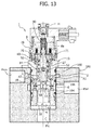
- Figure 14 illustrates, by way of example, an embodiment of the solenoid valve 1 that envisages the use of dynamic-seal rings designated by the reference number 130.
- the pressure chamber C connected to the mouth 2 and the actuator of the intake valve 7A connected to the mouth 4 will be set in the discharging condition and the leaks of fluid will have a direction going from the environment connected to the mouth 4 to the environment connected to the mouth 6.
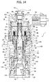
- Figure 15 illustrates a second embodiment of a solenoid valve according to the invention and designated by the reference number 200.
- the solenoid valve 200 comprises a first mouth 202 for inlet of a working fluid, and a second mouth 204 and a third mouth 206 for outlet of said working fluid.
- the solenoid valve 200 can assume the three operating positions P1, P2, P3 described previously, establishing the hydraulic connection between the mouths 202, 204 and 206 as described previously. This means that in the position P1a passage of fluid from the first mouth 202 to the second mouth 204 and the third mouth 206 is enabled, in the position P2 a passage of fluid from the first mouth 202 to the third mouth 206 is enabled, whereas the passage of fluid from the mouth 202 to the mouth 204 is disabled; finally, in the position P3 the passage of fluid from the mouth 202 tow the mouths 204 and 206 is completely disabled.
- An electromagnet 208 comprising a solenoid 208a can be controlled for causing a switching of the operating positions P1, P2, P3 of the solenoid valve 200, as will be described in detail hereinafter.
- the solenoid valve 200 comprises a plurality of components coaxial with one another and sharing a main axis H'.
- the solenoid valve 200 comprises a jacket 210, housed in which are a first valve element 212 and a second valve element 214 and fixed on which is the solenoid 208a, carried by a supporting bushing 209.
- the jacket 210 is traversed by a through hole sharing the axis H' and comprising a first stretch 216 having a diameter D216 and a second stretch 218 comprising a diameter D218, where the diameter D218 is greater than the diameter D216. At the interface between the two holes there is thus created a shoulder 219.
- the mouths 202, 206 are provided by means of through holes with radial orientation made, respectively, in positions corresponding to the stretch 216 and to the stretch 218 and in communication therewith.
- first annular groove 220 a first annular groove 220, a second annular groove 222, and a third annular groove 224, each designed to receive a gasket of an O-ring type, set on opposite sides with respect to the radial holes that define the mouth 202 and the radial holes that define the mouth 206.
- the mouth 206 is comprised between the grooves 222 and 224, while the mouth 2 is comprised between the grooves 220 and 222.
- the three annular grooves 220, 222, 224 are provided with the same seal diameter so as to minimize the unbalancing induced by the resultant of the forces of pressure acting on the outer surface of the jacket 210, which otherwise would be such as to jeopardize fixing of the jacket of the solenoid valve in the corresponding seat provided on a component or in an oleodynamic circuit where it is installed.
- the first valve element 212 is substantially configured as a hollow tubular element comprising a stem 226 - which is hollow and provided in which is a first cylindrical recess 227 -, a neck 228, and a head 230, which has a conical contrast surface 232 and a collar 234.
- the neck 228 has a diameter smaller than that of the stem 226.
- a ring of axial holes 234A preferably provided in the collar 234 is a ring of axial holes 234A, while a second cylindrical recess 235 having diameter D235 is provided in the head 230.
- the stem 226 of the valve element 212 is slidably mounted within the stretch 216 in such a way that the latter functions as guide element and as dynamic-seal element for the valve element 212 itself: the dynamic seal is thus provided between the environment giving out into which is the first mouth 202 and the environment giving out into which is the second mouth 204. As has been described previously, this, however, gives rise to slight leakages of fluid through the gaps existing between the valve element 212 and the stretch 216, contributing to defining the hydraulic consumption of the solenoid valve 200.
- the axial length of the stem 226 is chosen in such a way that it will extend along the stretch 216 as far as the holes that define the mouth 202, which thus occupy a position corresponding to the neck 228, which provides substantially an annular fluid chamber.
- the head 230 is positioned practically entirely within the stretch 218, except for a small surface portion 232 that projects within the stretch 216 beyond the shoulder 219.
- the head 230 has a diameter greater than the diameter D216 but smaller than the diameter D218, so that provided in a position corresponding to the shoulder 19 is a first valve seat A1' for the valve element 212, in particular for the conical surface 232.
- annular chamfer in a position corresponding to the shoulder 219 an annular chamfer is made that increases the area of contact with the conical surface 232, at the same time reducing the specific pressure developed at the contact therewith, hence minimizing the risks of damage to the surface 232. It in any case important for the seal diameter between the valve element 212 and the shoulder 219 to be substantially equal to the diameter D216.
- the bushing 238 houses a spacer ring 240, fixed with respect to the first valve element 212, bearing upon which is a first elastic-return element 242 housed within the recess 227.
- the choice of the band width of the spacer ring 240 enables adjustment of the pre-load of the elastic element 242.
- Fixed at the opposite end of the jacket 210 is a second bushing 244 having a neck 246 fitted on which is the supporting bushing 209.
- the bushing 244 constitutes a portion of the magnetic core of the electromagnet 8 and offers a contrast surface to a spacer ring 248 that enables adjustment of the stroke of the first valve element 212 and functions as contrast surface for the latter against the action of the elastic element 242.
- the bushing 238 functions as contrast for the elastic element 242 in so far as the elastic forces resulting from the deformation of the elastic element are discharged thereon.
- the second valve element 214 is set practically entirely within the bushing 244.
- the latter comprises a central through hole 250 that gives out into a cylindrical recess 252, facing the valve element 212.
- the valve element 214 comprises a stem 254 that bears upon a head 256, both of which are coaxial to one another and are arranged sharing the axis H', where the stem 254 is slidably mounted within the hole 250, whereas the head 256 is slidably mounted within the recess 252.
- the stem 254 simply bears upon the head 256 since - as will emerge more clearly - during operation it exerts an action of thrust (and not of pull) on the head 256, but in other embodiments a rigid connection between the stem 254 and the head 256 may be envisaged.
- the stem 254 is, instead, rigidly connected to the anchor 264.
- the head 256 further comprises a conical contrast surface 258 designed to co-operate with a second valve seat A2' defined by the internal edge of the recess 235.
- a spacer ring 260 Set between the head 256 and the bottom of the recess 252 is a spacer ring 260, the band width of which determines the stroke of the second valve element 214.
- the spacer ring 260 offers a contrast surface to the valve element 214, in particular to the head 256, in regard to the return action developed by a second elastic-return element 262, bearing at one end on the head 256 and at another end on the bushing 238.
- the elastic element 262 is set sharing the axis H' and inside the elastic element 242.
- the stem 254 is rigidly connected to an anchor 264 of the electromagnet 208, which bears upon a spring 266 used as positioning element.
- the maximum travel of the anchor 266 is designated by c'.
- the stroke of the anchor 266 is chosen so as to be equal to or greater than the maximum displacement allowed for the valve element 214.
- part of the fluid In traversing the first gap, part of the fluid can come out through the holes that define the third mouth 206, whilst another part of the fluid traverses the holes 234a and proceeds towards the second gap.
- the valve element 214 is hydraulically balanced because the seal diameter, coinciding with the diameter D235 of the valve seat A2', is substantially equal to the guide diameter, i.e., the diameter of the recess 252.
- the aforesaid first movement is imparted on the valve element 214 by means of circulation, in the solenoid 208a, of a current having an intensity I 1 sufficient to displace the anchor 264 by just the distance necessary to bring the valve element to bear upon the seat A2' and to overcome the resistance of just the elastic element 262.
- valve element 214 is hydraulically balanced since the seal diameter, i.e., the diameter of the valve seat A2', is equal to the diameter of the recess 252 in which the head 256 is guided and slidably mounted.
- the second valve element 214 remains in contact against the first valve element 212 maintaining the hydraulic connection between the mouths 202 and 206 closed.
- Figures 16 and 17 of the annexed drawings show the diagrams of valve lift of the engine intake valves according to the invention, and the corresponding diagrams of the current supplying the solenoid of the solenoid valve in the case where the solenoid valve is used by switching it only between the position P1 and the position P2, i.e., between the conditions illustrated, respectively, in Figure 4 and in Figure 5 .
- the two intake valves associated to each cylinder of the engine are governed identically with respect to one another, i.e., as occurs in a conventional system with solenoid valves with just two positions, as illustrated in Figure 3 .
- the diagram at the top left in Figure 16 shows a full-lift mode in which both of the intake valves of each cylinder of the engine are controlled in a traditional way, getting each of them to perform the full lift that is governed by the respective cam of the distribution shaft of the engine.
- the diagram shows the lift H of both of the valves as a function of the engine angle ⁇ .
- the part at the bottom left of Figure 16 shows the diagram of the current supplying the solenoid of the solenoid valve in the aforesaid full-lift mode.
- the solenoid valve is brought from the position P1 to the position P2 (condition illustrated in Figure 5 ), where both of the valves 7A, 7B are coupled to the tappet. This is obtained by supplying the solenoid with a first current level I 1 .
- Figure 16 shows, by way of example, a diagram of current in which, according to a technique in itself known, the solenoid of the solenoid valve is supplied initially with a peak current I 1peak and immediately after with a hold current I 1hold throughout the revolution of the input shaft in which the tappet tends to open the intake valves. It is, however, possible to envisage a constant current level for each of the positions P2 and P3 of the solenoid valve.
- the top right-hand part of Figure 16 shows an early-closing mode of a traditional type, in which both of the intake valves associated to each cylinder of the engine are closed simultaneously in advance with respect to the end of the active phase of the respective tappet so that the valve-lift diagram - for both of the valves - is the one illustrated with a solid line in the top right-hand part of Figure 16 , instead of the one illustrated with a dashed line (which coincides with the preceding full-lift case).
- the bottom right-hand part of Figure 16 shows the corresponding diagram of the current supplying the solenoid.
- the solenoid valve is brought into the position P2 as in the case of full lift, but then the current supplying the solenoid is set to zero in advance with respect to the end of the active phase of the tappet, so that the solenoid valve returns into the position P1, and both of the intake valves associated to each cylinder return into the closed condition in advance with respect to the end of the active phase of the respective tappet.
- Figure 17 of the annexed drawings shows another two operating modes of a known type, where both of the intake valves associated to each cylinder are controlled in such a way that the law of motion of each is identical to the other by switching the solenoid valve that controls them only between the positions P1 and P2: consequently represented with a solid line is the displacement of both.
- the part at the top left of Figure 17 shows the lift of both of the intake valves (solid-line plot) in a late-opening mode, where the solenoid of the solenoid valve is supplied with a current of level I 1 starting from an instant subsequent to start of the active phase of the tappet.
- each of the two intake valves does not present the full lift (illustrated by the dashed line in the part at the top left of Figure 17 ) but rather a reduced lift (illustrated with a solid line). Since in this case the intake valves of each cylinder are coupled to the respective cam after a certain time from start of the active phase of the tappet, the two valves will open with a reduced lift in so far as they will feel only the residual part of the profile of the respective actuation cam, which consequently leads to a re-closing of the valves in advance with respect to the full-lift case.
- the maximum displacement of the intake valves depends upon the amount of the volume of oil pumped into the element 21: the case of full lift of both of the intake valves corresponds to the case where the entire volume V stmax is used to move the aforesaid valves, which will consequently reach their maximum lift Smax. If the solenoid valve 24, intervening when the plunger is moving, sets a certain volume of oil in discharge, the stroke S of the intake valves will be less than Smax, and the difference Smax - S will be proportional to the volume bypassed by the solenoid valve 24: it is now understandable why in the left-hand diagram of Figure 17 the profile of the intake valves does not reach the maximum lift Smax.
- the current diagrams refer to an example in which the current level I 1 is obtained by reaching initially a peak level I 1peak and then bringing the current to a lower level I 1hold . It is evident, however, that also in this case the invention could be obtained by adopting simplified current profiles, without an initial peak level.
- FIG. 17 shows the diagram of the lift of both of the intake valves associated to each cylinder of the engine in a multi-lift mode where both of the intake valves do not present the full-lift profile illustrated with a dashed line, but rather open and re-close completely more than once during the active phase of the respective tappet (solid-line plot).
- the solenoid valve is initially brought into the position P2 so that both of the valves start to open, but then is sent back into the position P1, so as to close both of the valves completely.
- a new energization of the solenoid to the level I 1 causes a new displacement of the solenoid valve into the position P2 and then a new opening of both of the valves, which then re-close definitively as soon as the solenoid is de-energized for the second time.
- both of the intake valves open and close completely twice or more times.
- the operating modes illustrated in Figures 16, 17 and described above are conventional operating modes in Multiair ® systems, in so far as in this case the three-position solenoid valve is used as solenoid valve with just two positions, in a way similar to conventional Multiair systems.
- the left-hand section of Figure 18 shows an operating mode in which the valve B is governed in full-lift mode, i.e., so as to get it to perform a conventional cycle of opening during the active phase of the respective tappet.
- the valve A is controlled in a delayed-opening mode, in which the valve A opens with a delay with respect to the valve B.
- Said operating mode is obtained by supplying the solenoid of the solenoid valve according to the current profile illustrated in the left-hand section of the bottom part of Figure 18 .
- the solenoid is initially supplied at a current level I 2 such as to bring the solenoid valve from the position P1 to the position P3 (condition illustrated in Figure 6 ).
- the current supplying the solenoid is reduced to a level I 1hold that is kept throughout the residual part of the active phase of the tappet.
- the solenoid valve passes from the position P3 illustrated in Figure 6 to the position P2 illustrated in Figure 5 . Consequently, in the case of the mode illustrated in the left-hand part of Figure 18 , the solenoid valve is initially brought into the position P3 ( Figure 6 ) so that only the valve B is coupled to the respective tappet and only the valve B then opens according to the conventional lift profile. Consequently, in the first part of the active phase of the tappet the valve A remains closed.
- the solenoid valve passes from the position P3 illustrated in Figure 6 to the position P2 illustrated in Figure 5 so as to couple both of the valves A, B to the respective tappet. Consequently, starting from said instant, also the valve A opens. Hence, in this case, opening of the valve A occurs with a delay with respect to opening of the valve B.
- the valve A feels the effect of the respective tappet throughout the residual part of the active phase of the tappet so that it has a valve-lift diagram corresponding to the dashed line in the left-hand section of the top part of Figure 18 and closes together with the valve B.
- the right-hand section of the top part of Figure 18 shows a further mode of control of the intake valves.
- the valve B has a conventional opening cycle, being coupled to the respective tappet throughout the active phase of the tappet.
- the valve A presents, instead, a lift profile represented with a dashed line in the right-hand section of the top part of Figure 18 .
- Said operating mode is obtained by supplying the solenoid of the solenoid valve according to a current profile illustrated in the right-hand section of the bottom part of Figure 18 .
- the solenoid of the solenoid valve is supplied with a current level I 1 (which usually, in the case of the example illustrated, envisages an initial peak level and a subsequent hold level).
- the supply current is then brought to the higher level I 2 (once again, in the specific example, achieving an initial peak level and then a hold level).
- the current supplying the solenoid is then brought to zero in an instant subsequent to the end of the active phase of the tappet.
- the valve B is controlled in full-lift mode, whereas the valve A is controlled in a delayed-closing mode.
- the solenoid valve is supplied at level I 1 and is hence in the position P2 illustrated in Figure 5 .
- both of the intake valves A and B open, as may be seen from the diagrams in the right-hand section of Figure 18 .
- the current supplying the solenoid is brought to the level I 2 , so that the solenoid valve passes into the position P3, illustrated in Figure 6 , where the valve B remains coupled to the tappet, whilst the valve A is isolated. Consequently, in said condition the valve A remains in the open position where it is at the moment in which the solenoid valve is brought into the position P3.
- the current level I 2 is kept even after the end of the active phase of the tappet, so that, in said control mode, the valve A remains blocked in the aforesaid open position even after the end of the active phase of the tappet. It returns into the closed condition only when the current supplying the solenoid of the solenoid valve is brought back to zero, so that the solenoid valve returns into the position P1.
- one of the two intake valves is governed in a conventional way, whilst the other intake valve is partially opened and then kept in said partially open position even after the end of the active phase of the respective tappet.
- the duration of the phase in which the intake valve A is blocked in the aforesaid partially open position can be fixed at will since it is a function of the pre-selected current profile.
- valve A can remain blocked in the partially open position for any angular range of rotation of the input shaft at each turn of the input shaft, if need be, even through 360° (obviously choosing a degree of opening such that the valve A will not come into contact with the piston when this is at the top dead centre, or else adopting for the geometry of the piston itself geometrical solutions that will prevent said contact; moreover, the motion of the valve A when the solenoid valve 24 is in the position P3 is affected by the leakages of said solenoid valve 24).
- Figure 19 shows the valve-lift diagrams and the corresponding current diagrams for two further operating modes, in which both of the intake valves associated to each cylinder of the engine are controlled in multi-lift mode (i.e., with a number of cycles of complete opening and closing throughout the active phase of the tappet), the cycles of the two valves A, B being differentiated from one another.
- the top left-hand part of Figure 19 shows a mode in which both the valve A and the valve B present two cycles of complete opening and closing instead of the conventional cycle dictated by the shape of the cam (illustrated with a dashed and dotted line).
- the diagrams with a dashed line refer to the valve A, whilst those with the solid line refer to the valve B.
- Said operating mode is used by supplying the solenoid according to the current profiles visible in the bottom left-hand part of Figure 19 ; as may be seen, the current supplying the solenoid is initially brought to the level I 2 so as to bring the solenoid valve into the position P3 and govern only opening of the valve B.
- the current is brought to the level I 1 so as to bring the solenoid valve into the position P2 and govern opening also of the valve A.
- the current is then brought back to zero so as to re-close both of the valves A and B completely at the end of the first sub-cycle. Said operation is then repeated so as to obtain a further sub-cycle of complete opening and closing of the two valves B and A before the active phase of the tappet finishes.
- the right-hand part of Figure 19 refers to a further operating mode of the multi-lift type, in which a first sub-cycle of opening and closing of the valves B and A is envisaged identical to the one described above, and subsequently a second sub-cycle, in which the valve B is again governed in a way similar to what has been described above, whereas the valve A is isolated and kept blocked in the partially open position, in a way similar to what has been described above with reference to the right-hand section of Figure 18 .
- Said operating mode is obtained by means of the current profile visible in the bottom right-hand part of Figure 19 , which envisages a first sub-cycle similar to the one illustrated at the bottom left in Figure 19 , already described above, and a second sub-cycle in which the current supplying the solenoid is brought initially to the level I 1 to govern both of the valves A and B and then to the level I 2 to continue to govern the valve B and block the valve A in the partially open position in which it is until the current is again brought back to zero, with consequent re-closing of the intake valve A.
- Figure 20 illustrates a further two operating modes of the "multi-lift" type.
- the valve B has two opening and closing sub-cycles, similar to the ones illustrated in Figure 19 .
- the valve A has a first sub-cycle in which it opens together with the valve B and closes before the valve B, and a second sub-cycle in which it opens together with the valve B and remains open also after closing of the valve B, remaining blocked in a partially open position.
- Figure 20A shows three examples of single-lift mode. In all three cases the solenoid of the solenoid valve is never supplied with the current level I 1 so that the solenoid valve is never brought stably into the position P2.
- valve B is controlled in multi-lift mode, with two opening and closing sub-cycles similar to those of Figures 19 and 20 .
- the valve B has a single opening and closing cycle, with closing advanced with respect to the conventional cycle dictated by the cam.
- the valve B is controlled with a single opening and closing cycle, with delayed opening and advanced closing with respect to the conventional cycle dictated by the cam.
- the electronic control unit for control of the solenoid valves is programmed for executing one or more of the aforesaid modes for controlling the intake valves as a function of the operating conditions of the engine.
- the control unit receives the signals coming from means for detecting or determining one or more parameters indicating the operating conditions of the engine, amongst which, for example, the engine load (position of the accelerator), the engine r.p.m., the engine temperature, the temperature of the engine coolant, the temperature of the engine lubricating oil, the temperature of the fluid used in the system for variable actuation of the engine valves, the temperature of the actuators of the intake valves, or other parameters still.
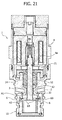
- Figures 21 and 22 illustrate a further embodiment of the solenoid valve, conceptually similar to that of Figure 9A .
- the parts corresponding to those of Figure 9A are designated by the same reference number.
- the solenoid valve illustrated in Figures 21 and 22 differs only for some constructional details from that of Figure 9A , for example for the different arrangement of the openings 68 associated to the valve element 14.
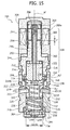
- Figure 23 illustrates a further embodiment, which likewise entails a different arrangement of the openings 68 obtained in the valve element 14 and a different arrangement of the electromagnet, which in this case envisages an anchor 71 constituted by the top part of the body of the valve element 14 that penetrates axially into the central opening of the solenoid 8a.
- a further difference of the valve of Figure 23 lies in the fact that in this case the spring 52 that recalls the valve element 12 towards the resting position is set on the outside of said element instead of on the inside.
- Figure 24 shows a further variant of the solenoid valve of the system according to the invention, which is characterized by a series of additional arrangements (which, on the other hand, can be adopted also in the other embodiments illustrated above).
- Figure 24 the parts in common with those illustrated in Figures 9A , 13-15 and 21-23 are designated by the same reference numbers.
- a first important characteristic of the solenoid valve of Figure 24 lies in the fact that both of the springs 86, 52 that recall the two valve elements 14 and 12 are set outside the solenoid 8a. Consequently, within the solenoid 8a there can be provided a solid fixed body 800, which affords a greater magnetic flux that attracts towards the body 800 the head 71a of an anchor, the stem 71 of which carries the valve body 14 at the bottom end.
- the head 71a has channels 71b, 71c that enable communication of the pressure of the fluid that circulates in the valve on both sides of the head 71 a so as to prevent any unbalancing.
- a further preferred characteristic consists in providing a tubular insert 801 made of non-magnetic material (for example, AISI 400 steel) guided within which is the head 71a. In this way, the lines of magnetic flux are forced to follow the path indicated by F, passing around the insert 801 and rendering the magnetic force that attracts the head 71a towards the body 800 maximum.
- non-magnetic material for example, AISI 400 steel
- an elastic ring (circlip) 900 is provided, which withholds the unit with the two valve elements inside the body 10.
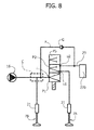
- Figure 25 of the annexed drawings shows a variant of the bottom part of Figure 18 that corresponds to the idea underlying the present invention.
- the solenoid of the control valve is configured for being supplied only by three different values of electric current:
- the solenoid is never supplied at a level of peak current I1peak for bringing the valve into its first position, but always and only at a single current level I1, whereas, whenever the control valve is brought into its third position P3, the solenoid is supplied first at a peak value I2peak, which has precisely the purpose of displacing the mobile members of the valve, and then to a lower value I2hold, for holding the position.
- the above arrangement which envisages a single current level for the position P2 and two current levels for the position P3, enables energy saving, without reducing the efficiency and the necessary promptness of operation of the control valve.
- the control unit designed for control of the valve is simplified and inexpensive.
- the electrically actuated control valve in all the embodiments, can be obtained with any other type of electric or electromagnetic actuator instead of the solenoid.
Claims (14)
- Brennkraftmaschine, umfassend für jeden Zylinder:- einen Brennraum;- mindestens zwei Einlasskanäle (4) und mindestens einen Auslasskanal (6), die sich in den Brennraum verteilen;- mindestens zwei Einlassventile (7A, 7B) und mindestens ein Auslassventil (70), die mit den Einlass- und Auslasskanälen (4, 6) verbunden sind und mit jeweiligen Schließfedern (9), die sie in eine geschlossene Stellung schieben, versehen sind;- eine Nockenwelle (11) zum Betätigen der Einlassventile (7A, 7B) durch jeweilige Ventilstößel (15);- wobei jedes Einlassventil (7A, 7B) durch den jeweiligen Ventilstößel (15) gegen die Wirkung der zuvor erwähnten Schließfeder (9) gesteuert wird durch Einschaltung hydraulischer Einrichtungen einschließlich eines Druckfluidraums (C), dem ein mit dem Ventilstößel (15) des Ventils verbundener Vorverdichtungskolben (16) gegenüberliegt, wobei der Druckfluidraum ausgelegt ist, so dass er mit dem Raum eines jedem Einlassventil zugeordneten, hydraulischen Stellelements (21) in Verbindung steht;- ein einzelnes, elektrisch betätigtes oder elektromagnetisch betätigtes Steuerventil (24), das den Einlassventilen jedes Zylinders zugeordnet und ausgelegt ist, so dass der Druckfluidraum (C) mit einem Abgaskanal (23) in Verbindung gesetzt wird, um das Einlassventil von dem jeweiligen Ventilstößel (15) zu entkoppeln und schnelles Schließen der Einlassventile als Wirkung der jeweiligen Schließfedern (9) zu veranlassen; und- eine elektronische Steuereinrichtung (25) zum Steuern des Steuerventils (24), um den genauen Öffnungszeitpunkt und/oder den genauen Schließzeitpunkt und den Hub jedes Einlassventils als eine Funktion eines oder mehrerer Betriebsparameter der Maschine zu verändern,wobei die Maschine dadurch gekennzeichnet ist, dass das jedem Zylinder zugeordnete Steuerventil (24) ein Dreiwegeventil mit drei Stellungen ist, das umfasst:- einen Einlass (i), der mit dem Druckfluidraum (C) und mit dem Stellelement eines Einlassventils (7B) ständig in Verbindung steht; und- zwei Auslässe (u1, u2), die jeweils mit dem Stellelement des zweiten Einlassventils (7A) und mit dem Abgaskanal in Verbindung stehen, wobeidas Steuerventil (24) die folgenden drei Betriebsstellungen aufweist:- eine erste Stellung (P1), in welcher der Einlass (i) mit beiden Auslässen (u1, u2) in Verbindung steht, so dass der Druckfluidraum (C), d.h. die Stellelemente beider Einlassventile (7A, 7B) in einen Ausstoßzustand gesetzt werden und die Einlassventile (7A, 7B) beide durch ihre Schließfedern geschlossen gehalten werden;- eine zweite Stellung (P2), in welcher der Einlass (i) nur mit dem mit dem Stellelement des zweiten Einlassventils (7A) verbundenen Auslass (u1) in Verbindung steht, und stattdessen nicht mit dem mit dem Abgaskanal (23) verbundenen Auslass (u2) in Verbindung steht, so dass der Druckraum (C) von dem Abgaskanal (23) getrennt ist, die Stellelemente beider Einlassventile (7A, 7B) mit dem Druckraum (C) in Verbindung stehen und die Einlassventile (7A, 7B) damit beide aktiv sind; und- eine dritte Stellung (P3), in welcher der Einlass nicht mit einem der zwei Auslässe (u1, u2) in Verbindung steht, so dass der zuvor erwähnte Druckraum (C) von dem Abgaskanal getrennt ist, und das oben erwähnte erste Einlassventil (7B) aktiv ist, während das zweite Einlassventil (7A) von dem Druckraum (C) und von dem Abgaskanal (23) getrennt ist,das Steuerventil (24) ein elektrisches Stellelement aufweist, das gestaltet ist, um nur bei drei unterschiedlichen Werten elektrischen Stroms versorgt zu werden:- einem ersten Stromwert (I1), um das Steuerventil (24) in seine oben erwähnte zweite Stellung (P2) zu bringen und es in der Stellung zu halten;- einem zweiten Spitzenstromwert (12 Höchstwert), höher als der erste Wert (I1), um das Steuerventil in seine oben erwähnte dritte Stellung (P3) zu bringen; und- einem dritten Haltestromwert (12 Verweilzeit), kleiner als der zweite Spitzenwert (12 Höchstwert) und höher als der erste Wert (I1), um das Steuerventil in der dritten Stellung (P3) zu halten, sobald es in die dritte Stellung gebracht wurde.
- Maschine nach Anspruch 1, dadurch gekennzeichnet, dass die elektronische Steuereinrichtung (25) programmiert wird, um bei einem oder mehreren gegebenen Betriebszuständen der Maschine eine weitere Regelart des Ventils (24) auszuführen, bei der:- das Steuerventil in die zweite Stellung (P2) in einer aktiven Phase des Ventilstößels gebracht wird, in welcher der Ventilstößel (15) dazu neigt, das Öffnen des zweiten Einlassventils (7A) zu bewirken, so dass das zweite Einlassventil (7A) öffnet;- das Steuerventil (24) anschließend von der zweiten Stellung (P2) in die dritte Stellung (P3) im Verlauf der aktiven Phase des Ventilstößels gebracht wird, in welcher der Ventilstößel das Öffnen des zweiten Einlassventils (7A) derart steuert, dass das hydraulische Stellelement des zweiten Einlassventils (7A) getrennt bleibt, und das zweite Einlassventil (7A) in der offenen Stellung, in der es sich bereits befindet, gesperrt bleibt;- das Steuerventil (24) in der zweiten Stellung (P2) auch nach dem Ende der aktiven Phase des Ventilstößels gehalten wird, so dass das zweite Einlassventil (7A) in der offenen Stellung gesperrt bleibt, auch wenn der Ventilstößel (15) nicht mehr dazu neigt, es offen zu halten.
- Maschine nach Anspruch 1, dadurch gekennzeichnet, dass die elektronische Steuereinrichtung (25) programmiert wird, um bei einem oder mehreren gegebenen Betriebszuständen der Maschine eine weitere Regelart des Magnetventils (24) auszuführen, bei der das Magnetventil in die zuvor erwähnte dritte Stellung (P3) zu Beginn der zuvor erwähnten aktiven Phase des jeweiligen Ventilstößels gebracht wird, um anfangs nur das Öffnen des ersten Einlassventils (7B) zu bewirken, und anschließend im Verlauf der aktiven Phase des Ventilstößels das Magnetventil in seine zweite Stellung (P2) gebracht wird, so dass das Öffnen des zweiten Einlassventils (7A) mit einer Verzögerung bezüglich des Öffnens des ersten Einlassventils (7B) bewirkt wird, das Magnetventil in der zweiten Stellung (P2) bis zum Ende der aktiven Phase des Ventilstößels gehalten wird.
- Maschine nach Anspruch 1, dadurch gekennzeichnet, dass die elektronische Steuereinrichtung (25) programmiert wird, um bei einem oder mehreren gegebenen Betriebszuständen der Maschine eine Regelart des Ventils (24) auszuführen, bei der das Steuerventil (24) im Verlauf der zuvor erwähnten aktiven Phase des Ventilstößels mehrmals zuerst in eine zwischen der zweiten und dritten Stellung (P2, P3), dann in die andere zwischen der zweiten und dritten Stellung (P2, P3) und anschließend in seine erste Stellung (P1) gebracht wird, so dass jedes der mit jedem Zylinder der Maschine verbundenen zwei Einlassventile (7A, 7B) zwei oder mehrere untergeordnete Takte des vollständigen Öffnens und Schließens im Verlauf der aktiven Phase des jeweiligen Ventilstößels durchführt, wobei die untergeordneten Takte der zwei Einlassventile (7A, 7B) voneinander unterschieden werden.
- Maschine nach Anspruch 4, dadurch gekennzeichnet, dass die elektronische Steuereinrichtung (25) programmiert wird, derart, dass in mindestens einem der untergeordneten Takte das Steuerventil zuerst in die zuvor erwähnte dritte Stellung (P3), dann in die zuvor erwähnte zweite Stellung (P2) und anschließend in die zuvor erwähnte erste Stellung (P1) derart gebracht wird, dass der untergeordnete Takt anfangs das Öffnen nur des ersten Einlassventils (7B), dann das Öffnen auch des zweiten Einlassventils (7A) und anschließend das Schließen beider Einlassventile (7A, 7B) umfasst.
- Maschine nach Anspruch 4, dadurch gekennzeichnet, dass zumindest in einem der untergeordneten Takte zu einem ersten Zeitpunkt ein Durchgang des Steuerventils von seiner ersten Stellung (P1) in seine zweite Stellung (P2), dann ein Durchgang des Steuerventils von seiner zweiten Stellung (P2) in seine dritte Stellung (P3) und anschließend eine Rückführung des Steuerventils in seine erste Stellung (P1) derart beabsichtigt ist, dass zu Beginn des untergeordneten Taktes beide Einlassventile (7A, 7B) öffnen und anschließend das erste Einlassventil (7B) vollständig schließt, während das zweite Einlassventil (7A) in der offenen Stellung, in welcher es sich bereits befindet, gesperrt bleibt, bis das Magnetventil am Ende des untergeordneten Taktes in seine erste Stellung (P1) gebracht wird.
- Brennkraftmaschine nach Anspruch 1, dadurch gekennzeichnet, dass die elektronische Steuereinrichtung (25) programmiert wird, um in einem oder mehreren gegebenen Betriebszuständen der Maschine eine Regelart des Steuerventils (24) auszuführen, bei der zumindest während eines Teils der aktiven Phase des Ventilstößels das Ventil (24) in der dritten Stellung (P3) gehalten wird, um das erste Einlassventil (7B) aktiv zu machen, wogegen während der gesamten aktiven Phase des Ventilstößels das Steuerventil (24) durchaus nicht in seine zweite Stellung (P2) gebracht wird, so dass das zweite Einlassventil (7A) immer geschlossen bleibt.
- Maschine nach Anspruch 1, dadurch gekennzeichnet, dass das elektrisch betätigte Steuerventil (1; 200) umfasst:- einen Ventilkörper mit einer ersten Öffnung, einer zweiten Öffnung und einer dritten Öffnung (2, 4, 6; 202, 204, 206), die zur Bildung des einen Einlasses und der anderen Auslässe des Magnetventils verwendet werden können;- ein erstes Ventilelement (12; 212) und ein zweites Ventilelement (14; 214), die jeweils mit einem ersten Ventilsitz (A1; A1') und mit einem zweiten Ventilsitz (A1; A2') zusammenwirken;- Federmittel, die dazu neigen, das erste und das zweite Ventilelement (12, 14; 212, 214) in einer Öffnungsstellung in einem Abstand von den jeweiligen Ventilsitzen (A1, A2; A1', A2') zu halten; und- ein elektrisches Stellelement, das gestaltet ist, um Schließen nur des ersten Ventil-elements (12; 212) gegen den ersten Ventilsitz (A1, A1') oder Schließen von beiden der ersten und zweiten Ventilelemente (12, 14; 212, 214) gegen die jeweiligen Ventilsitze (A1, A2; A1', A2') zu bewirken.
- Maschine nach Anspruch 8, dadurch gekennzeichnet, dass:- das erste Ventilelement (12; 212) und der erste Ventilsitz (A1, A1') vorher angeordnet werden, um den Fluiddurchgang von der ersten Öffnung (2; 202) zu der dritten Öffnung (6; 206) zu steuern; und- das zweite Ventilelement (14; 214) und der zweite Ventilsitz (A2; A2') vorher angeordnet werden, um den Fluiddurchgang von der ersten Öffnung (2; 202) zu der zweiten Öffnung (4; 204) zu steuern.
- Maschine nach Anspruch 9, dadurch gekennzeichnet, dass sich die ersten und zweiten Ventilelemente (12, 14; 212, 214) die gleiche Achse (H) teilen und hydraulisch druckentlastet sind.
- Maschine nach Anspruch 10, dadurch gekennzeichnet, dass der zweite Ventilsitz (A2; A2') auf dem ersten Ventilelement (12; 212) festgelegt ist.
- Maschine nach einem der vorhergehenden Ansprüche, dadurch gekennzeichnet, dass sie Einrichtungen zum Fühlen oder Bestimmen eines oder mehrerer Parameter umfasst, die gewählt sind aus Last, Motordrehzahl, Motortemperatur, Temperatur des Motorkühlmittels, Temperatur des Motorschmieröls, Temperatur des im System zur veränderlichen Betätigung der Motorenventile verwendeten Fluides und Temperatur der Stellelemente der Einlassventile; und dadurch, dass die elektronische Steuereinrichtung (25) zum Ausführen einer oder mehrerer Regelarten der Einlassventile entsprechend Signalen, die durch die Fühl- oder Bestimmungseinrichtungen gesendet werden, programmiert wird.
- Verfahren zum Steuern einer Brennkraftmaschine, wobei die Maschine für jeden Zylinder umfasst:- einen Brennraum;- mindestens zwei Einlasskanäle (4) und mindestens einen Auslasskanal (6), die sich in den Brennraum verteilen;- mindestens zwei Einlassventile (7A, 7B) und mindestens ein Auslassventil (70), die mit den Einlass- und Auslasskanälen (4, 6) verbunden und mit jeweiligen Schließfedern (9) versehen sind, die sie in eine geschlossene Stellung schieben;- eine Nockenwelle (11) zum Betätigen der Einlassventile (7A, 7B) durch jeweilige Ventilstößel (15);- wobei jedes Einlassventil (7A, 7B) durch den jeweiligen Ventilstößel (15) gegen die Wirkung der zuvor erwähnten Schließfeder (9) gesteuert wird durch Einschaltung hydraulischer Einrichtungen einschließlich eines Druckfluidraums (C), dem ein mit dem Ventilstößel (15) des Ventils verbundener Vorverdichtungskolben (16) gegenüberliegt, wobei der Druckfluidraum ausgelegt ist, um mit dem Raum eines jedem Einlassventil zugeordneten hydraulischen Stellelements (21) in Verbindung zu stehen;- ein einzelnes Steuerventil (24), das den Einlassventilen jedes Zylinders zugeordnet und so ausgelegt ist, dass der Druckfluidraum (C) mit einem Abgaskanal (23) in Verbindung gesetzt wird, um das Einlassventil von dem jeweiligen Ventilstößel (15) zu entkoppeln und schnelles Schließen der Einlassventile als Wirkung der jeweiligen Schließfedern (9) zu veranlassen; und- eine elektronische Steuereinrichtung (25) zum Steuern des Steuerventils (24), um den genauen Öffnungszeitpunkt und/oder den genauen Schließzeitpunkt und den Hub jedes Einlassventils als eine Funktion eines oder mehrerer Betriebsparameter der Maschine zu verändern,wobei das Verfahren dadurch gekennzeichnet ist, dass das mit jedem Zylinder verbundene Steuerventil ein Dreiwegeventil mit drei Stellungen ist, das umfasst:- einen Einlass (i), der mit dem Druckfluidraum (C) und mit dem Stellelement eines Einlassventils (7B) ständig in Verbindung steht; und- zwei Auslässe (u1, u2), die jeweils mit dem Stellelement des zweiten Einlassventils (7A) und mit dem Abgaskanal in Verbindung stehen, wobeidas Steuerventil die folgenden drei Betriebsstellungen aufweist:- eine erste Stellung (P1), in welcher der Einlass (i) in Verbindung mit beiden der Auslässe (u1, u2) steht, so dass die Stellelemente beider Einlassventile (7A, 7B) in einen Ausstoßzustand gesetzt werden und die Einlassventile (7A, 7B) beide durch ihre Schließfedern geschlossen gehalten werden;- eine zweite Stellung (P2), in welcher der Einlass (i) nur mit dem an das Stellelement des zweiten Einlassventils (7A) angeschlossenen Auslass (u1) in Verbindung steht und stattdessen nicht mit dem Auslass (u2) in Verbindung steht, der an den Abgaskanal (23) angeschlossen ist, so dass der Druckraum (C) von dem Abgaskanal (23) getrennt ist, die Stellelemente beider Einlassventile (7A, 7B) mit dem Druckraum (C) in Verbindung stehen und die Einlassventile (7A, 7B) damit beide aktiv sind; und- eine dritte Stellung (P3), in welcher der Einlass nicht mit einem der zwei Auslässe (u1, u2) in Verbindung steht, so dass der zuvor erwähnte Druckraum (C) von dem Abgaskanal getrennt ist, und das oben erwähnte erste Einlassventil (7B) aktiv ist, während das zweite Einlassventil (7A) von dem Druckraum (C) und von dem Abgaskanal (23) getrennt ist,wobei das Verfahren außerdem dadurch gekennzeichnet ist, dass das Steuerventil (24) ein elektrisches Stellelement aufweist, das nur bei drei unterschiedlichen Werten elektrischen Stroms versorgt wird:- einem ersten Stromwert (I1), um das Steuerventil (24) in seine zuvor erwähnte zweite Stellung (P2) zu bringen und es in der Stellung zu halten;- einem zweiten Spitzenstromwert (12 Höchstwert), höher als der erste Wert (I1), um das Steuerventil in seine zuvor erwähnte dritte Stellung (P3) zu bringen; und- einem dritten Haltestromwert (12 Verweilzeit), kleiner als der zweite Spitzenwert (12 Höchstwert) und höher als der erste Wert (I1), um das Steuerventil in der dritten Stellung (P3) zu halten, sobald es in die dritte Stellung gebracht wurde.
- Verfahren nach Anspruch 11, dadurch gekennzeichnet, dass die elektronische Steuereinrichtung (25) zur Regelung der Steuerventile programmiert wird, um eine oder mehrere Regelarten der Einlassventile als eine Funktion der Betriebszustände der Maschine auszuführen, wobei die Betriebszustände auf der Basis eines oder mehrerer Parameter gekennzeichnet sind, die aus: Last, Motordrehzahl, Motortemperatur, Temperatur des Motorkühlmittels, Temperatur des Motorschmieröls, Temperatur des in dem System zur veränderlichen Betätigung der Motorventile verwendeten Fluides und Temperatur der Stellelemente der Einlassventile gewählt werden.
Priority Applications (2)
| Application Number | Priority Date | Filing Date | Title |
|---|---|---|---|
| EP13167181.0A EP2801706B1 (de) | 2013-05-09 | 2013-05-09 | Brennkraftmaschine, mit einem System zur variablen Betätigung der Einlassventile, welches ausgerüstet ist mit einem elektrischen 3-Wegeventil, welches mit 3 unterschiedlichen Stromstärken bestromt werden kann, und verfahren zur Steuerung dieser Brennkraftmaschine. |
| US14/271,782 US9127576B2 (en) | 2013-05-09 | 2014-05-07 | Internal-combustion engine, with system for variable actuation of the intake valves provided with a three-way electric valve having three levels of supply current, and method for controlling said engine |
Applications Claiming Priority (1)
| Application Number | Priority Date | Filing Date | Title |
|---|---|---|---|
| EP13167181.0A EP2801706B1 (de) | 2013-05-09 | 2013-05-09 | Brennkraftmaschine, mit einem System zur variablen Betätigung der Einlassventile, welches ausgerüstet ist mit einem elektrischen 3-Wegeventil, welches mit 3 unterschiedlichen Stromstärken bestromt werden kann, und verfahren zur Steuerung dieser Brennkraftmaschine. |
Publications (2)
| Publication Number | Publication Date |
|---|---|
| EP2801706A1 EP2801706A1 (de) | 2014-11-12 |
| EP2801706B1 true EP2801706B1 (de) | 2016-06-15 |
Family
ID=48747293
Family Applications (1)
| Application Number | Title | Priority Date | Filing Date |
|---|---|---|---|
| EP13167181.0A Active EP2801706B1 (de) | 2013-05-09 | 2013-05-09 | Brennkraftmaschine, mit einem System zur variablen Betätigung der Einlassventile, welches ausgerüstet ist mit einem elektrischen 3-Wegeventil, welches mit 3 unterschiedlichen Stromstärken bestromt werden kann, und verfahren zur Steuerung dieser Brennkraftmaschine. |
Country Status (2)
| Country | Link |
|---|---|
| US (1) | US9127576B2 (de) |
| EP (1) | EP2801706B1 (de) |
Cited By (1)
| Publication number | Priority date | Publication date | Assignee | Title |
|---|---|---|---|---|
| EP4180640A1 (de) | 2021-11-16 | 2023-05-17 | C.R.F. Società Consortile per Azioni | Multi-zylinder brennkraftmaschine, mit zylindern ausgerüstet mit variablen einlass-ventiltrieben, deren hydraulische schaltkreise sich überkreuzen |
Families Citing this family (8)
| Publication number | Priority date | Publication date | Assignee | Title |
|---|---|---|---|---|
| EP2796675B1 (de) * | 2013-04-26 | 2016-11-23 | C.R.F. Società Consortile per Azioni | Brennkraftmaschine mit Ventiltrieb zur variablen Betätigung der Einlassventile mit Drei-Weg Solenoidventilen und Verfahren zur Kontrolle dieser Brennkraftmaschine in einem "einzigen-Hub" Modus |
| EP3181842B1 (de) | 2015-12-17 | 2019-06-19 | C.R.F. Società Consortile per Azioni | System und verfahren zur variablen betätigung eines ventils einer brennkraftmaschine mit einem elektrisch betätigten steuerventil mit verbesserter steuerung |
| GB2552500B (en) * | 2016-07-26 | 2019-11-06 | Jaguar Land Rover Ltd | Controlling intake valves in an internal combustion engine |
| CN108240244B (zh) * | 2017-12-29 | 2023-12-19 | 潍柴动力股份有限公司 | 柴油机进气门可变系统及柴油机 |
| EP3832077A1 (de) | 2019-12-02 | 2021-06-09 | C.R.F. Società Consortile per Azioni | Brennkraftmaschine mit schneller verbrennung und verfahren zur steuerung der maschine |
| EP3832078B1 (de) | 2019-12-02 | 2022-07-27 | C.R.F. Società Consortile per Azioni | System und verfahren zur variablen betätigung der ventile eines verbrennungsmotors |
| EP4015787B1 (de) | 2020-12-17 | 2024-01-24 | C.R.F. Società Consortile per Azioni | Brennkraftmaschine mit schneller verbrennung und verfahren zur steuerung der maschine |
| EP4043700A1 (de) | 2021-02-16 | 2022-08-17 | C.R.F. Società Consortile per Azioni | Brennkraftmaschine mit schneller verbrennung und verfahren zur steuerung einer brennkraftmaschine |
Citations (4)
| Publication number | Priority date | Publication date | Assignee | Title |
|---|---|---|---|---|
| EP2597276A1 (de) * | 2011-11-24 | 2013-05-29 | C.R.F. Società Consortile per Azioni | Brennkraftmaschine mit variablem Ventiltrieb mit einem drei-weg Solenoidventil |
| EP2693007A1 (de) * | 2012-07-31 | 2014-02-05 | C.R.F. Società Consortile per Azioni | Verbrennungsmotor mit einem System zur variablen Betätigung der Einlassventile mit Dreiwege-Magnetventilen und Verfahren zur Steuerung des Motors |
| WO2014128526A1 (en) * | 2013-02-20 | 2014-08-28 | C.R.F. Società Consortile Per Azioni | Internal-combustion engine having a system for variable actuation of the intake valves, provided with three-way solenoid valves |
| EP2796675A1 (de) * | 2013-04-26 | 2014-10-29 | C.R.F. Società Consortile per Azioni | Brennkraftmaschine mit Ventiltrieb zur variablen Betätigung der Einlassventile mit Drei-Weg Solenoidventilen und Verfahren zur Kontrolle dieser Brennkraftmaschine in einem "einzigen-Hub" Modus |
Family Cites Families (10)
| Publication number | Priority date | Publication date | Assignee | Title |
|---|---|---|---|---|
| DE2658927A1 (de) * | 1976-12-24 | 1978-07-06 | Maschf Augsburg Nuernberg Ag | Bremseinrichtung fuer viertakt-hubkolbenbrennkraftmaschinen |
| US5499606A (en) * | 1995-01-11 | 1996-03-19 | Siemens Automotive Corporation | Variable timing of multiple engine cylinder valves |
| IT1285853B1 (it) | 1996-04-24 | 1998-06-24 | Fiat Ricerche | Motore a combustione interna con valvole ad azionamento variabile. |
| ITTO20010660A1 (it) | 2001-07-06 | 2003-01-06 | Fiat Ricerche | Motore diesel pluricilindrico con azionamento variabile delle valvole. |
| EP1555398B1 (de) | 2004-01-16 | 2007-02-28 | C.R.F. Società Consortile per Azioni | Brennkraftmaschine mit einer einzigen obenliegenden Nockenwelle zur mechanischen Steuerung der Auslassventile und zur elektrohydraulischen Steuerung der Einlassventile |
| BRPI0516108A (pt) * | 2004-10-14 | 2008-08-26 | Jacobs Vehicle Systems Inc | sistema para ativação de válvula de motor em um motor à combustão interna |
| PL1674673T3 (pl) | 2004-12-23 | 2007-08-31 | Fiat Ricerche | Silnik spalinowy z hydraulicznie zmiennymi zaworami |
| EP1728978B1 (de) | 2005-05-24 | 2007-10-31 | C.R.F. Società Consortile per Azioni | Vorrichtung und Verfahren zur Kontrolle der Last und der Verbrennung in einer Brennkraftmaschine durch eine Ventilbetätigung mit mehrfachem Ventilhub pro Zyklus |
| US7594485B2 (en) * | 2006-12-26 | 2009-09-29 | Caterpillar Inc. | Valve actuation system for internal combustion engine |
| EP2261471B1 (de) | 2009-05-25 | 2014-09-17 | C.R.F. Società Consortile per Azioni | Brennkraftmaschine mit zwei hydraulische Einlassventile mit unterschiedlichen Ventilschliessfedern für jede Zylinder |
-
2013
- 2013-05-09 EP EP13167181.0A patent/EP2801706B1/de active Active
-
2014
- 2014-05-07 US US14/271,782 patent/US9127576B2/en active Active
Patent Citations (4)
| Publication number | Priority date | Publication date | Assignee | Title |
|---|---|---|---|---|
| EP2597276A1 (de) * | 2011-11-24 | 2013-05-29 | C.R.F. Società Consortile per Azioni | Brennkraftmaschine mit variablem Ventiltrieb mit einem drei-weg Solenoidventil |
| EP2693007A1 (de) * | 2012-07-31 | 2014-02-05 | C.R.F. Società Consortile per Azioni | Verbrennungsmotor mit einem System zur variablen Betätigung der Einlassventile mit Dreiwege-Magnetventilen und Verfahren zur Steuerung des Motors |
| WO2014128526A1 (en) * | 2013-02-20 | 2014-08-28 | C.R.F. Società Consortile Per Azioni | Internal-combustion engine having a system for variable actuation of the intake valves, provided with three-way solenoid valves |
| EP2796675A1 (de) * | 2013-04-26 | 2014-10-29 | C.R.F. Società Consortile per Azioni | Brennkraftmaschine mit Ventiltrieb zur variablen Betätigung der Einlassventile mit Drei-Weg Solenoidventilen und Verfahren zur Kontrolle dieser Brennkraftmaschine in einem "einzigen-Hub" Modus |
Cited By (1)
| Publication number | Priority date | Publication date | Assignee | Title |
|---|---|---|---|---|
| EP4180640A1 (de) | 2021-11-16 | 2023-05-17 | C.R.F. Società Consortile per Azioni | Multi-zylinder brennkraftmaschine, mit zylindern ausgerüstet mit variablen einlass-ventiltrieben, deren hydraulische schaltkreise sich überkreuzen |
Also Published As
| Publication number | Publication date |
|---|---|
| US9127576B2 (en) | 2015-09-08 |
| US20140331948A1 (en) | 2014-11-13 |
| EP2801706A1 (de) | 2014-11-12 |
Similar Documents
| Publication | Publication Date | Title |
|---|---|---|
| EP2693008B1 (de) | Verbrennungsmotor mit einem System zur variablen Betätigung der Einlassventile mit Dreiwege-Magnetventilen und Verfahren zur Steuerung des Motors | |
| EP2801706B1 (de) | Brennkraftmaschine, mit einem System zur variablen Betätigung der Einlassventile, welches ausgerüstet ist mit einem elektrischen 3-Wegeventil, welches mit 3 unterschiedlichen Stromstärken bestromt werden kann, und verfahren zur Steuerung dieser Brennkraftmaschine. | |
| EP2597276B1 (de) | Brennkraftmaschine mit variablem Ventiltrieb mit einem Drei-Wege-Solenoidventil | |
| EP2796675B1 (de) | Brennkraftmaschine mit Ventiltrieb zur variablen Betätigung der Einlassventile mit Drei-Weg Solenoidventilen und Verfahren zur Kontrolle dieser Brennkraftmaschine in einem "einzigen-Hub" Modus | |
| US9791055B2 (en) | Three-way three-position control valve having a piezoelectric or magnetostrictive actuator, and fuel-injection system comprising the aforesaid valve | |
| US20100294220A1 (en) | Internal combustion engine with two intake valves per cylinder which are ac tuated hydraulically and have differentiated return springs | |
| US6584885B2 (en) | Variable lift actuator | |
| US20080041467A1 (en) | Digital control valve assembly for a hydraulic actuator | |
| US10156163B2 (en) | System and method for variable actuation of a valve of an internal-combustion engine, with a device for dampening pressure oscillations | |
| EP2832960B1 (de) | Brennkraftmaschine mit variabler Ventilbetätigungseinrichtung für Einlassventile, mit elektrisch betätigten Stellventil vom Typ mit zwei Wegen und drei Stellungen | |
| WO2014128526A1 (en) | Internal-combustion engine having a system for variable actuation of the intake valves, provided with three-way solenoid valves | |
| JP5421350B2 (ja) | 改良ソレノイドバルブを備えた吸気バルブの可変駆動システムを有する内燃エンジン、および同エンジン用ソレノイドバルブ | |
| EP3832078B1 (de) | System und verfahren zur variablen betätigung der ventile eines verbrennungsmotors | |
| JP4079063B2 (ja) | 内燃機関用燃料噴射装置 | |
| JP2005105870A (ja) | 内燃機関用燃料噴射装置 | |
| JPH0988756A (ja) | 燃料噴射装置 |
Legal Events
| Date | Code | Title | Description |
|---|---|---|---|
| PUAI | Public reference made under article 153(3) epc to a published international application that has entered the european phase |
Free format text: ORIGINAL CODE: 0009012 |
|
| 17P | Request for examination filed |
Effective date: 20140325 |
|
| AK | Designated contracting states |
Kind code of ref document: A1 Designated state(s): AL AT BE BG CH CY CZ DE DK EE ES FI FR GB GR HR HU IE IS IT LI LT LU LV MC MK MT NL NO PL PT RO RS SE SI SK SM TR |
|
| AX | Request for extension of the european patent |
Extension state: BA ME |
|
| 17Q | First examination report despatched |
Effective date: 20141201 |
|
| GRAP | Despatch of communication of intention to grant a patent |
Free format text: ORIGINAL CODE: EPIDOSNIGR1 |
|
| INTG | Intention to grant announced |
Effective date: 20160104 |
|
| GRAS | Grant fee paid |
Free format text: ORIGINAL CODE: EPIDOSNIGR3 |
|
| GRAA | (expected) grant |
Free format text: ORIGINAL CODE: 0009210 |
|
| AK | Designated contracting states |
Kind code of ref document: B1 Designated state(s): AL AT BE BG CH CY CZ DE DK EE ES FI FR GB GR HR HU IE IS IT LI LT LU LV MC MK MT NL NO PL PT RO RS SE SI SK SM TR |
|
| REG | Reference to a national code |
Ref country code: CH Ref legal event code: EP Ref country code: GB Ref legal event code: FG4D |
|
| REG | Reference to a national code |
Ref country code: IE Ref legal event code: FG4D |
|
| REG | Reference to a national code |
Ref country code: AT Ref legal event code: REF Ref document number: 806626 Country of ref document: AT Kind code of ref document: T Effective date: 20160715 |
|
| REG | Reference to a national code |
Ref country code: DE Ref legal event code: R096 Ref document number: 602013008530 Country of ref document: DE |
|
| REG | Reference to a national code |
Ref country code: LT Ref legal event code: MG4D |
|
| REG | Reference to a national code |
Ref country code: NL Ref legal event code: MP Effective date: 20160615 |
|
| PG25 | Lapsed in a contracting state [announced via postgrant information from national office to epo] |
Ref country code: NO Free format text: LAPSE BECAUSE OF FAILURE TO SUBMIT A TRANSLATION OF THE DESCRIPTION OR TO PAY THE FEE WITHIN THE PRESCRIBED TIME-LIMIT Effective date: 20160915 Ref country code: LT Free format text: LAPSE BECAUSE OF FAILURE TO SUBMIT A TRANSLATION OF THE DESCRIPTION OR TO PAY THE FEE WITHIN THE PRESCRIBED TIME-LIMIT Effective date: 20160615 Ref country code: FI Free format text: LAPSE BECAUSE OF FAILURE TO SUBMIT A TRANSLATION OF THE DESCRIPTION OR TO PAY THE FEE WITHIN THE PRESCRIBED TIME-LIMIT Effective date: 20160615 |
|
| REG | Reference to a national code |
Ref country code: AT Ref legal event code: MK05 Ref document number: 806626 Country of ref document: AT Kind code of ref document: T Effective date: 20160615 |
|
| PG25 | Lapsed in a contracting state [announced via postgrant information from national office to epo] |
Ref country code: HR Free format text: LAPSE BECAUSE OF FAILURE TO SUBMIT A TRANSLATION OF THE DESCRIPTION OR TO PAY THE FEE WITHIN THE PRESCRIBED TIME-LIMIT Effective date: 20160615 Ref country code: GR Free format text: LAPSE BECAUSE OF FAILURE TO SUBMIT A TRANSLATION OF THE DESCRIPTION OR TO PAY THE FEE WITHIN THE PRESCRIBED TIME-LIMIT Effective date: 20160916 Ref country code: RS Free format text: LAPSE BECAUSE OF FAILURE TO SUBMIT A TRANSLATION OF THE DESCRIPTION OR TO PAY THE FEE WITHIN THE PRESCRIBED TIME-LIMIT Effective date: 20160615 Ref country code: NL Free format text: LAPSE BECAUSE OF FAILURE TO SUBMIT A TRANSLATION OF THE DESCRIPTION OR TO PAY THE FEE WITHIN THE PRESCRIBED TIME-LIMIT Effective date: 20160615 Ref country code: SE Free format text: LAPSE BECAUSE OF FAILURE TO SUBMIT A TRANSLATION OF THE DESCRIPTION OR TO PAY THE FEE WITHIN THE PRESCRIBED TIME-LIMIT Effective date: 20160615 Ref country code: LV Free format text: LAPSE BECAUSE OF FAILURE TO SUBMIT A TRANSLATION OF THE DESCRIPTION OR TO PAY THE FEE WITHIN THE PRESCRIBED TIME-LIMIT Effective date: 20160615 |
|
| PG25 | Lapsed in a contracting state [announced via postgrant information from national office to epo] |
Ref country code: RO Free format text: LAPSE BECAUSE OF FAILURE TO SUBMIT A TRANSLATION OF THE DESCRIPTION OR TO PAY THE FEE WITHIN THE PRESCRIBED TIME-LIMIT Effective date: 20160615 Ref country code: IS Free format text: LAPSE BECAUSE OF FAILURE TO SUBMIT A TRANSLATION OF THE DESCRIPTION OR TO PAY THE FEE WITHIN THE PRESCRIBED TIME-LIMIT Effective date: 20161015 Ref country code: EE Free format text: LAPSE BECAUSE OF FAILURE TO SUBMIT A TRANSLATION OF THE DESCRIPTION OR TO PAY THE FEE WITHIN THE PRESCRIBED TIME-LIMIT Effective date: 20160615 Ref country code: CZ Free format text: LAPSE BECAUSE OF FAILURE TO SUBMIT A TRANSLATION OF THE DESCRIPTION OR TO PAY THE FEE WITHIN THE PRESCRIBED TIME-LIMIT Effective date: 20160615 Ref country code: SK Free format text: LAPSE BECAUSE OF FAILURE TO SUBMIT A TRANSLATION OF THE DESCRIPTION OR TO PAY THE FEE WITHIN THE PRESCRIBED TIME-LIMIT Effective date: 20160615 |
|
| PG25 | Lapsed in a contracting state [announced via postgrant information from national office to epo] |
Ref country code: ES Free format text: LAPSE BECAUSE OF FAILURE TO SUBMIT A TRANSLATION OF THE DESCRIPTION OR TO PAY THE FEE WITHIN THE PRESCRIBED TIME-LIMIT Effective date: 20160615 Ref country code: PT Free format text: LAPSE BECAUSE OF FAILURE TO SUBMIT A TRANSLATION OF THE DESCRIPTION OR TO PAY THE FEE WITHIN THE PRESCRIBED TIME-LIMIT Effective date: 20161017 Ref country code: SM Free format text: LAPSE BECAUSE OF FAILURE TO SUBMIT A TRANSLATION OF THE DESCRIPTION OR TO PAY THE FEE WITHIN THE PRESCRIBED TIME-LIMIT Effective date: 20160615 Ref country code: AT Free format text: LAPSE BECAUSE OF FAILURE TO SUBMIT A TRANSLATION OF THE DESCRIPTION OR TO PAY THE FEE WITHIN THE PRESCRIBED TIME-LIMIT Effective date: 20160615 Ref country code: BE Free format text: LAPSE BECAUSE OF FAILURE TO SUBMIT A TRANSLATION OF THE DESCRIPTION OR TO PAY THE FEE WITHIN THE PRESCRIBED TIME-LIMIT Effective date: 20160615 Ref country code: PL Free format text: LAPSE BECAUSE OF FAILURE TO SUBMIT A TRANSLATION OF THE DESCRIPTION OR TO PAY THE FEE WITHIN THE PRESCRIBED TIME-LIMIT Effective date: 20160615 |
|
| REG | Reference to a national code |
Ref country code: DE Ref legal event code: R097 Ref document number: 602013008530 Country of ref document: DE |
|
| PLBE | No opposition filed within time limit |
Free format text: ORIGINAL CODE: 0009261 |
|
| STAA | Information on the status of an ep patent application or granted ep patent |
Free format text: STATUS: NO OPPOSITION FILED WITHIN TIME LIMIT |
|
| 26N | No opposition filed |
Effective date: 20170316 |
|
| REG | Reference to a national code |
Ref country code: FR Ref legal event code: PLFP Year of fee payment: 5 |
|
| PG25 | Lapsed in a contracting state [announced via postgrant information from national office to epo] |
Ref country code: DK Free format text: LAPSE BECAUSE OF FAILURE TO SUBMIT A TRANSLATION OF THE DESCRIPTION OR TO PAY THE FEE WITHIN THE PRESCRIBED TIME-LIMIT Effective date: 20160615 |
|
| PG25 | Lapsed in a contracting state [announced via postgrant information from national office to epo] |
Ref country code: LU Free format text: LAPSE BECAUSE OF NON-PAYMENT OF DUE FEES Effective date: 20170531 Ref country code: SI Free format text: LAPSE BECAUSE OF FAILURE TO SUBMIT A TRANSLATION OF THE DESCRIPTION OR TO PAY THE FEE WITHIN THE PRESCRIBED TIME-LIMIT Effective date: 20160615 |
|
| REG | Reference to a national code |
Ref country code: CH Ref legal event code: PL |
|
| GBPC | Gb: european patent ceased through non-payment of renewal fee |
Effective date: 20170509 |
|
| PG25 | Lapsed in a contracting state [announced via postgrant information from national office to epo] |
Ref country code: MC Free format text: LAPSE BECAUSE OF FAILURE TO SUBMIT A TRANSLATION OF THE DESCRIPTION OR TO PAY THE FEE WITHIN THE PRESCRIBED TIME-LIMIT Effective date: 20160615 |
|
| REG | Reference to a national code |
Ref country code: IE Ref legal event code: MM4A |
|
| PG25 | Lapsed in a contracting state [announced via postgrant information from national office to epo] |
Ref country code: CH Free format text: LAPSE BECAUSE OF NON-PAYMENT OF DUE FEES Effective date: 20170531 Ref country code: LI Free format text: LAPSE BECAUSE OF NON-PAYMENT OF DUE FEES Effective date: 20170531 |
|
| PG25 | Lapsed in a contracting state [announced via postgrant information from national office to epo] |
Ref country code: LU Free format text: LAPSE BECAUSE OF NON-PAYMENT OF DUE FEES Effective date: 20170509 |
|
| PG25 | Lapsed in a contracting state [announced via postgrant information from national office to epo] |
Ref country code: GB Free format text: LAPSE BECAUSE OF NON-PAYMENT OF DUE FEES Effective date: 20170509 Ref country code: IE Free format text: LAPSE BECAUSE OF NON-PAYMENT OF DUE FEES Effective date: 20170509 |
|
| REG | Reference to a national code |
Ref country code: FR Ref legal event code: PLFP Year of fee payment: 6 |
|
| PG25 | Lapsed in a contracting state [announced via postgrant information from national office to epo] |
Ref country code: MT Free format text: LAPSE BECAUSE OF NON-PAYMENT OF DUE FEES Effective date: 20170509 |
|
| PG25 | Lapsed in a contracting state [announced via postgrant information from national office to epo] |
Ref country code: AL Free format text: LAPSE BECAUSE OF FAILURE TO SUBMIT A TRANSLATION OF THE DESCRIPTION OR TO PAY THE FEE WITHIN THE PRESCRIBED TIME-LIMIT Effective date: 20160615 |
|
| PG25 | Lapsed in a contracting state [announced via postgrant information from national office to epo] |
Ref country code: HU Free format text: LAPSE BECAUSE OF FAILURE TO SUBMIT A TRANSLATION OF THE DESCRIPTION OR TO PAY THE FEE WITHIN THE PRESCRIBED TIME-LIMIT; INVALID AB INITIO Effective date: 20130509 |
|
| PG25 | Lapsed in a contracting state [announced via postgrant information from national office to epo] |
Ref country code: BG Free format text: LAPSE BECAUSE OF FAILURE TO SUBMIT A TRANSLATION OF THE DESCRIPTION OR TO PAY THE FEE WITHIN THE PRESCRIBED TIME-LIMIT Effective date: 20160615 |
|
| PG25 | Lapsed in a contracting state [announced via postgrant information from national office to epo] |
Ref country code: CY Free format text: LAPSE BECAUSE OF FAILURE TO SUBMIT A TRANSLATION OF THE DESCRIPTION OR TO PAY THE FEE WITHIN THE PRESCRIBED TIME-LIMIT Effective date: 20160615 |
|
| PG25 | Lapsed in a contracting state [announced via postgrant information from national office to epo] |
Ref country code: MK Free format text: LAPSE BECAUSE OF FAILURE TO SUBMIT A TRANSLATION OF THE DESCRIPTION OR TO PAY THE FEE WITHIN THE PRESCRIBED TIME-LIMIT Effective date: 20160615 |
|
| PG25 | Lapsed in a contracting state [announced via postgrant information from national office to epo] |
Ref country code: TR Free format text: LAPSE BECAUSE OF FAILURE TO SUBMIT A TRANSLATION OF THE DESCRIPTION OR TO PAY THE FEE WITHIN THE PRESCRIBED TIME-LIMIT Effective date: 20160615 |
|
| REG | Reference to a national code |
Ref country code: DE Ref legal event code: R079 Ref document number: 602013008530 Country of ref document: DE Free format text: PREVIOUS MAIN CLASS: F01L0009020000 Ipc: F01L0009100000 |
|
| PGFP | Annual fee paid to national office [announced via postgrant information from national office to epo] |
Ref country code: IT Payment date: 20230420 Year of fee payment: 11 Ref country code: FR Payment date: 20230420 Year of fee payment: 11 Ref country code: DE Payment date: 20230419 Year of fee payment: 11 |