EP2801701A1 - Turbine blade - Google Patents
Turbine blade Download PDFInfo
- Publication number
- EP2801701A1 EP2801701A1 EP12856805.2A EP12856805A EP2801701A1 EP 2801701 A1 EP2801701 A1 EP 2801701A1 EP 12856805 A EP12856805 A EP 12856805A EP 2801701 A1 EP2801701 A1 EP 2801701A1
- Authority
- EP
- European Patent Office
- Prior art keywords
- cooling air
- wall surface
- blade body
- turbine blade
- air hole
- Prior art date
- Legal status (The legal status is an assumption and is not a legal conclusion. Google has not performed a legal analysis and makes no representation as to the accuracy of the status listed.)
- Granted
Links
Images



Classifications
-
- F—MECHANICAL ENGINEERING; LIGHTING; HEATING; WEAPONS; BLASTING
- F01—MACHINES OR ENGINES IN GENERAL; ENGINE PLANTS IN GENERAL; STEAM ENGINES
- F01D—NON-POSITIVE DISPLACEMENT MACHINES OR ENGINES, e.g. STEAM TURBINES
- F01D5/00—Blades; Blade-carrying members; Heating, heat-insulating, cooling or antivibration means on the blades or the members
- F01D5/12—Blades
- F01D5/14—Form or construction
- F01D5/18—Hollow blades, i.e. blades with cooling or heating channels or cavities; Heating, heat-insulating or cooling means on blades
-
- F—MECHANICAL ENGINEERING; LIGHTING; HEATING; WEAPONS; BLASTING
- F01—MACHINES OR ENGINES IN GENERAL; ENGINE PLANTS IN GENERAL; STEAM ENGINES
- F01D—NON-POSITIVE DISPLACEMENT MACHINES OR ENGINES, e.g. STEAM TURBINES
- F01D5/00—Blades; Blade-carrying members; Heating, heat-insulating, cooling or antivibration means on the blades or the members
- F01D5/12—Blades
- F01D5/14—Form or construction
- F01D5/18—Hollow blades, i.e. blades with cooling or heating channels or cavities; Heating, heat-insulating or cooling means on blades
- F01D5/186—Film cooling
-
- F—MECHANICAL ENGINEERING; LIGHTING; HEATING; WEAPONS; BLASTING
- F01—MACHINES OR ENGINES IN GENERAL; ENGINE PLANTS IN GENERAL; STEAM ENGINES
- F01D—NON-POSITIVE DISPLACEMENT MACHINES OR ENGINES, e.g. STEAM TURBINES
- F01D9/00—Stators
- F01D9/06—Fluid supply conduits to nozzles or the like
- F01D9/065—Fluid supply or removal conduits traversing the working fluid flow, e.g. for lubrication-, cooling-, or sealing fluids
-
- F—MECHANICAL ENGINEERING; LIGHTING; HEATING; WEAPONS; BLASTING
- F05—INDEXING SCHEMES RELATING TO ENGINES OR PUMPS IN VARIOUS SUBCLASSES OF CLASSES F01-F04
- F05D—INDEXING SCHEME FOR ASPECTS RELATING TO NON-POSITIVE-DISPLACEMENT MACHINES OR ENGINES, GAS-TURBINES OR JET-PROPULSION PLANTS
- F05D2240/00—Components
- F05D2240/80—Platforms for stationary or moving blades
- F05D2240/81—Cooled platforms
-
- F—MECHANICAL ENGINEERING; LIGHTING; HEATING; WEAPONS; BLASTING
- F05—INDEXING SCHEMES RELATING TO ENGINES OR PUMPS IN VARIOUS SUBCLASSES OF CLASSES F01-F04
- F05D—INDEXING SCHEME FOR ASPECTS RELATING TO NON-POSITIVE-DISPLACEMENT MACHINES OR ENGINES, GAS-TURBINES OR JET-PROPULSION PLANTS
- F05D2250/00—Geometry
- F05D2250/20—Three-dimensional
- F05D2250/21—Three-dimensional pyramidal
-
- F—MECHANICAL ENGINEERING; LIGHTING; HEATING; WEAPONS; BLASTING
- F05—INDEXING SCHEMES RELATING TO ENGINES OR PUMPS IN VARIOUS SUBCLASSES OF CLASSES F01-F04
- F05D—INDEXING SCHEME FOR ASPECTS RELATING TO NON-POSITIVE-DISPLACEMENT MACHINES OR ENGINES, GAS-TURBINES OR JET-PROPULSION PLANTS
- F05D2250/00—Geometry
- F05D2250/20—Three-dimensional
- F05D2250/23—Three-dimensional prismatic
-
- F—MECHANICAL ENGINEERING; LIGHTING; HEATING; WEAPONS; BLASTING
- F05—INDEXING SCHEMES RELATING TO ENGINES OR PUMPS IN VARIOUS SUBCLASSES OF CLASSES F01-F04
- F05D—INDEXING SCHEME FOR ASPECTS RELATING TO NON-POSITIVE-DISPLACEMENT MACHINES OR ENGINES, GAS-TURBINES OR JET-PROPULSION PLANTS
- F05D2260/00—Function
- F05D2260/20—Heat transfer, e.g. cooling
- F05D2260/202—Heat transfer, e.g. cooling by film cooling
-
- F—MECHANICAL ENGINEERING; LIGHTING; HEATING; WEAPONS; BLASTING
- F05—INDEXING SCHEMES RELATING TO ENGINES OR PUMPS IN VARIOUS SUBCLASSES OF CLASSES F01-F04
- F05D—INDEXING SCHEME FOR ASPECTS RELATING TO NON-POSITIVE-DISPLACEMENT MACHINES OR ENGINES, GAS-TURBINES OR JET-PROPULSION PLANTS
- F05D2260/00—Function
- F05D2260/20—Heat transfer, e.g. cooling
- F05D2260/221—Improvement of heat transfer
- F05D2260/2212—Improvement of heat transfer by creating turbulence
-
- F—MECHANICAL ENGINEERING; LIGHTING; HEATING; WEAPONS; BLASTING
- F23—COMBUSTION APPARATUS; COMBUSTION PROCESSES
- F23R—GENERATING COMBUSTION PRODUCTS OF HIGH PRESSURE OR HIGH VELOCITY, e.g. GAS-TURBINE COMBUSTION CHAMBERS
- F23R2900/00—Special features of, or arrangements for continuous combustion chambers; Combustion processes therefor
- F23R2900/03042—Film cooled combustion chamber walls or domes
-
- F—MECHANICAL ENGINEERING; LIGHTING; HEATING; WEAPONS; BLASTING
- F23—COMBUSTION APPARATUS; COMBUSTION PROCESSES
- F23R—GENERATING COMBUSTION PRODUCTS OF HIGH PRESSURE OR HIGH VELOCITY, e.g. GAS-TURBINE COMBUSTION CHAMBERS
- F23R2900/00—Special features of, or arrangements for continuous combustion chambers; Combustion processes therefor
- F23R2900/03043—Convection cooled combustion chamber walls with means for guiding the cooling air flow
-
- F—MECHANICAL ENGINEERING; LIGHTING; HEATING; WEAPONS; BLASTING
- F23—COMBUSTION APPARATUS; COMBUSTION PROCESSES
- F23R—GENERATING COMBUSTION PRODUCTS OF HIGH PRESSURE OR HIGH VELOCITY, e.g. GAS-TURBINE COMBUSTION CHAMBERS
- F23R2900/00—Special features of, or arrangements for continuous combustion chambers; Combustion processes therefor
- F23R2900/03045—Convection cooled combustion chamber walls provided with turbolators or means for creating turbulences to increase cooling
Definitions
- the present invention relates to a turbine blade.
- Patent Documents 1 to 4 discloses a turbine blade that partitions cooling air that is jetted out from a cooling hole with a projection.
- the present invention was achieved in view of the aforementioned circumstances, and has as its object to further raise the cooling effectiveness of turbine blades that a gas turbine engine and the like is provided with.
- the present invention adopts the following constitution.
- the first aspect of the present invention is a turbine blade that is provided with a cooling air hole that penetrates from the inner wall surface to the outer wall surface of a blade body that is made to be hollow, and provided with a convex portion that is arranged in the inner portion of the cooling air hole and that is provided projecting out from the inner wall surface of the cooling air hole.
- the convex portion is provided on the inner wall surface of the cooling air hole that is positioned at the downstream side of the flow direction of the main flow gas that flows along the outer wall surface of the blade body.
- the cooling air hole has a straight pipe portion that is provided at the inner wall surface side of the blade body and a diameter expansion portion that is provided at the outer wall surface side of the blade body, and the convex portion is provided at the straight pipe portion or at a connection region of the straight pipe portion and the diameter expansion portion.
- the cooling air hole has a straight pipe portion that is provided at the inner wall surface side of the blade body and a diameter expansion portion that is provided at the outer wall surface side of the blade body, and the convex portion is provided continuously from an end portion of the straight pipe portion on the inner wall surface side of the blade body to an end portion of the straight pipe portion on the outer wall surface side of the blade body.
- the convex portion is provided in the inner portion of the cooling air hole, the cooling air that has ridden over the convex portion is not affected by other flows such as a main flow gas. For this reason, it is possible to cause most of the cooling air that is jetted out from the cooling air hole to contribute to film cooling, without a portion of the cooling air being blown away by the main flow gas. Moreover, since the cooling air spreads out while flowing due to riding over the convex portion, it becomes possible to jet out the cooling air in a wider range.
- the present invention it is possible to jet out the cooling air in a wide range without reducing the cooling air that contributes to the cooling of the outer wall surface of the blade body, and so it is possible to raise the cooling effectiveness of the turbine blade.
- FIG. 1 is a perspective view that shows the outline configuration of the turbine blade 1 of the present embodiment.
- the turbine blade 1 of the present embodiment is a turbine stator blade, and is provided with a blade body 2, band portions 3 that sandwich the blade body 2, and a film cooling portion 4.
- the blade body 2 is arranged on the downstream side of a combustor that is not illustrated, and is arranged in the flow path of a combustion gas G (refer to FIG. 2A ) that is generated by the combustor.
- This blade body 2 is made to have a blade shape having a leading edge 2a, a trailing edge 2b, a positive pressure surface 2c, and a negative pressure surface 2b.
- the blade body 2 is made to be hollow, to have an interior space for guiding cooling air to the inside.
- a cooling air flow path not illustrated is connected to the interior space of the blade body 2 whereby, for example, air that is extracted from a compressor that is installed on the upstream side of the combustor is introduced as the cooling air.
- the band portions 3 are provided sandwiching the blade body 2 from the height direction of the blade body 2, and function as a portion of the flow path wall of the combustion gas G. These band portions 3 are integrated with the tip side and hub side of the blade body 2.
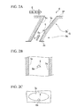
- FIG. 2A is a vertical cross-sectional view of an outline drawing of the film cooling portion 4.
- FIG. 2B is a plan view including a convex portion 6 described below of an outline drawing of the film cooling portion 4.
- FIG. 2C is a front elevation seen from the inner wall surface 2e side of the blade body 2 of an outline drawing of the film cooling portion 4. As shown in these drawings, the film cooling portion 4 is provided with a cooling air hole 5 and a convex portion 6.
- the cooling air hole 5 is a through-hole that penetrates from the inner wall surface 2e to the outer wall surface 2f of the blade body 2, and is constituted from a straight pipe portion 5a on the inner wall surface 2e side, and a diameter expansion portion 5b at the outer wall surface 2f side.
- the straight pipe portion 5a is a section that extends in a linear shape, and the cross section shown in FIG. 2A is made to have a long hole shape. Also, the straight pipe portion 5a is sloped so that the end portion of the outer wall surface 2f side is arranged further to the downstream side of the main flow gas G that flows along the outer wall surface 2f of the blade body 2 than the end portion on the inner wall surface 2e side.
- the diameter expansion portion 5b is a section whose flow path cross section increases heading toward the outer wall surface 2f. Note that the diameter expansion portion 5b is made to be a shape in which the side wall surface 5c shown in FIG. 2A, FIG. 2B, and FIG. 2C broadens in the height direction of the blade body 2 heading from the inner wall surface 2e side to the outer wall surface 2f side.
- This kind of cooling air hole 5 guides cooling air Y that is supplied from the interior space of the blade body 2 to the outer wall surface 2f, and after dispersing and spreading out the cooling air Y in the height direction of the blade body 2 in the diameter expansion portion 5b, jets it out it along the outer wall surface 2f.
- the convex portion 6 is arranged in the inner portion of the cooling air hole 5, and is provided projecting from the inner wall surface of the cooling air hole 5. As shown in FIG. 2A, FIG. 2B, and FIG. 2C , the convex portion 6 is made to have a triangular pyramid shape in which the inner wall surface 2e of the blade body 2 side of the convex portion 6 is made to be a triangular collision surface 6a. Also, the convex portion 6 is provided at a region positioned on the downstream side of the flow direction of the combustion gas G (main flow gas), in the inner wall surface of the cooling air hole 5. Moreover, the convex portion 6 is provided at a connection region of the straight pipe portion 5a and the diameter expansion portion 5b.
- a plurality of the film cooling portions 4 that are constituted as described above are provided in the turbine blade 1 of the present embodiment.
- the cooling air Y that is jetted out from this kind of film cooling portion 4 flows along the outer wall surface 2f of the blade body 2, and thereby the outer wall surface 2f of the blade body 2 is film cooled.
- the cooling air flows into the cooling air hole 5 of the film cooling portion 4 from the inner part of the blade body 2.
- the cooling air Y that has flowed into the cooling air hole 5 is guided in a straight manner by the straight pipe portion 5a in which the flow path surface area does not change, and in the diameter expansion portion 5b in which the flow path surface area widens in a continuous way, flows while spreading in the height direction of the blade body 2.
- the cooling air hole 5 that the turbine blade 1 of the present embodiment is provided with, compared with a cooling air hole that consists only of a straight pipe portion, it is possible to jet out the cooling air Y in a wider range in the height direction of the blade body 2, and so it is possible to cool the outer wall surface 2f of the blade body 2 in a wider range.
- the convex portion 6 is provided in the inner portion of the cooling air hole 5. For this reason, the cooling air Y that has ridden over the convex portion 6 is not affected by the flow of the combustion gas G. For this reason, it is possible to cause most of the cooling air Y that is jetted out from the cooling air hole 5 to contribute to film cooling, without a portion of the cooling air Y being blown away by the combustion gas G. Moreover, since the cooling air Y spreads out while flowing due to riding over the convex portion 6, it becomes possible to jet out the cooling air Y in a wider range.
- the turbine blade 1 of the present embodiment it is possible to jet out the cooling air Y in a wide range without reducing the cooling air Y that contributes to the cooling of the outer wall surface 2f of the blade body 2, and so it is possible to raise the cooling effectiveness of the turbine blade 1.
- the convex portion 6 in the turbine blade 1 of the present embodiment is arranged in the inner wall surface of the cooling air hole 5, on the downstream side of the flow direction of the combustion gas G that flows along the outer wall surface 2f of the blade body 2. Thereby, it becomes possible to broadly jet out the cooling air Y in the height direction of the blade body 2.
- the convex portion 6 is provided at the connection region of the straight pipe portion 5a and the diameter expansion portion 5b. Since the diameter expansion portion 5b is spatially wider than the straight pipe portion 5a, due to the provision of the convex portion 6 in the connection region of the straight pipe portion 5a and the diameter expansion portion 5b, it is possible to ensure a space for the cooling air Y, which attempts to spread out by riding over the convex portion 6, to spread out. Accordingly, it is possible to jet out the cooling air Y in a wider range without the spreading out of the cooling air Y being impeded.
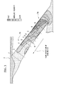
- FIG. 3 to FIG. 5 are drawings that schematically show the result of simulating flows in the film cooling portion 4 of the turbine blade 1 of the present embodiment.
- FIG. 3 shows the distribution of the absolute velocities of the cooling air Y in the film cooling portion 4
- FIG. 4 shows the absolute velocities and local flow directions of the cooling air Y at cross-section A to cross-section J in FIG. 3
- FIG. 5 shows the absolute velocities and local flow directions in the vicinity of the convex portion 6.
- the cooling air Y flows from the straight pipe portion 5a side toward the diameter expansion portion 5b.
- the local flow directions of the cooling air Y in the inner portion of the cooling air hole 5 are indicated with bold arrows.
- FIG. 6A is a vertical cross-sectional view of an outline drawing of the film cooling portion 4A that the turbine blade of the present embodiment is provided with.
- FIG. 6B is a plan view including a convex portion 7 described below of an outline drawing of the film cooling portion 4A that the turbine blade of the present embodiment is provided with.
- FIG. 6C is a front elevation seen from the inner wall surface 2e side of the blade body 2 of an outline drawing of the film cooling portion 4A that the turbine blade of the present embodiment is provided with.
- the film cooling portion 4A is provided with a convex portion 7 that is long in the direction that joins the inner wall surface 2e and the outer wall surface 2f of the blade body 2, instead of the convex portion 6 of the above embodiment.
- the convex portion 7 is arranged in the inner portion of the cooling air hole 5, and is provided projecting from the inner wall surface of the cooling air hole 5. Also, as shown in FIG. 6A, FIG. 6B, and FIG. 6C , the convex portion 7 is made to have a triangular column shape in which the inner wall surface 2e of the blade body 2 side of the convex portion 7 is made to be a triangle shaped. Also, the convex portion 7 is provided continuously from the end portion on the inner wall surface 2e of the blade body 2 side of the straight tube portion 5a to the end portion on the outer wall surface 2f of the blade body 2 side of the straight tube portion 5a.
- the cooling air Y that has ridden over the convex portion 7 is not affected by the flow of the combustion gas G. For this reason, it is possible to cause most of the cooling air Y that is jetted out from the cooling air hole 5 to contribute to film cooling, without a portion of the cooling air Y being blown away by the combustion gas G. Moreover, since the cooling air Y spreads out while flowing due to riding over the convex portion 7, it becomes possible to jet out the cooling air Y in a wider range.
- the arrangement position and number of the film cooling portion 4 in the blade body 2 of the aforementioned embodiments are just one example, and are suitably changeable in accordance with the cooling performance that is required in the turbine blade.
- the shape of the convex portions 6 and 7 in the aforementioned embodiments are just examples, and for example are changeable to other shapes such as a square column or a semicircular column shape.
- the convex portion 6 in the aforementioned embodiment may be installed in the inner portion of the straight pipe portion 5a.
- a turbine blade that a gas turbine engine or the like is provided with, it is possible to jet out cooling air in a wide range without reducing the cooling air that contributes to the cooling of the outer wall surface of a hollow blade body, and it is possible to raise the cooling effectiveness of the turbine blade.
Landscapes
- Engineering & Computer Science (AREA)
- Mechanical Engineering (AREA)
- General Engineering & Computer Science (AREA)
- Physics & Mathematics (AREA)
- Fluid Mechanics (AREA)
- Turbine Rotor Nozzle Sealing (AREA)
Abstract
Description
- The present invention relates to a turbine blade.
- Priority is claimed on Japanese Patent Application No.
2011-274336, filed December 15, 2011 - Turbine blades that a gas turbine engine or the like is provided with reach a high temperature due to being exposed to combustion gas generated by a combustor. For this reason, various countermeasures have been implemented as shown in
Patent Documents 1 to 4 in order to enhance the heat resistance of turbine blades. For example,Patent Document 3 discloses a turbine blade that partitions cooling air that is jetted out from a cooling hole with a projection. -
- [Patent Document 1] Japanese Patent No.
3997986 - [Patent Document 2] Japanese Patent No.
4752841 - [Patent Document 3] Japanese Unexamined Patent Application, First Publication No.
H10-89005 - [Patent Document 4] Japanese Unexamined Patent Application, First Publication No.
H06-093802 - However, in
Patent Document 3, since the top of the projection is open, the cooling air that rides over the projection is subject to being blown away by the main flow gas (combustion gas) that flows upward. That is to say, a portion of the cooling air ends up being blown away without heading along the outer wall surface of the blade body. For this reason, it is not possible to sufficiently improve the cooling effectiveness. - In recent years, further improvements in the output of gas turbine engines and the like have been sought, and thereby the temperature of the combustion gas generated in the combustor has more than ever before trended toward high temperatures.
- For this reason, further improvement of the cooling effectiveness is required for turbine blades that a gas turbine engine and the like is provided with.
- The present invention was achieved in view of the aforementioned circumstances, and has as its object to further raise the cooling effectiveness of turbine blades that a gas turbine engine and the like is provided with.
- The present invention adopts the following constitution.
- The first aspect of the present invention is a turbine blade that is provided with a cooling air hole that penetrates from the inner wall surface to the outer wall surface of a blade body that is made to be hollow, and provided with a convex portion that is arranged in the inner portion of the cooling air hole and that is provided projecting out from the inner wall surface of the cooling air hole.
- According to the second aspect of the present invention, in the first aspect, the convex portion is provided on the inner wall surface of the cooling air hole that is positioned at the downstream side of the flow direction of the main flow gas that flows along the outer wall surface of the blade body.
- According to the third aspect of the present invention, in the first or the second aspect, the cooling air hole has a straight pipe portion that is provided at the inner wall surface side of the blade body and a diameter expansion portion that is provided at the outer wall surface side of the blade body, and the convex portion is provided at the straight pipe portion or at a connection region of the straight pipe portion and the diameter expansion portion.
- According to the fourth aspect of the present invention, in the first or the second aspect, the cooling air hole has a straight pipe portion that is provided at the inner wall surface side of the blade body and a diameter expansion portion that is provided at the outer wall surface side of the blade body, and the convex portion is provided continuously from an end portion of the straight pipe portion on the inner wall surface side of the blade body to an end portion of the straight pipe portion on the outer wall surface side of the blade body.
- In the present invention, since the convex portion is provided in the inner portion of the cooling air hole, the cooling air that has ridden over the convex portion is not affected by other flows such as a main flow gas. For this reason, it is possible to cause most of the cooling air that is jetted out from the cooling air hole to contribute to film cooling, without a portion of the cooling air being blown away by the main flow gas. Moreover, since the cooling air spreads out while flowing due to riding over the convex portion, it becomes possible to jet out the cooling air in a wider range.
- According to the present invention, it is possible to jet out the cooling air in a wide range without reducing the cooling air that contributes to the cooling of the outer wall surface of the blade body, and so it is possible to raise the cooling effectiveness of the turbine blade.
-
-
FIG. 1 is a perspective view that shows an outline configuration of the turbine blade in the first embodiment of the present invention. -
FIG. 2A is a vertical cross-sectional view of an outline drawing of the film cooling portion that the turbine blade in the first embodiment of the present invention is provided with. -
FIG. 2B is a plan view including the convex portion of an outline drawing of the film cooling portion that the turbine blade in the first embodiment of the present invention is provided with. -
FIG. 2C is a front elevation seen from the inner wall surface side of the blade body of an outline drawing of the film cooling portion that the turbine blade in the first embodiment of the present invention is provided with. -
FIG. 3 is a schematic drawing that shows the distribution of the absolute velocities obtained by simulation that used the film cooling portion the turbine blade in the first embodiment of the present invention is provided with as a model. -
FIG. 4 is a schematic drawing that shows the absolute velocities and flow directions at cross section A to cross section J inFIG. 3 . -
FIG. 5 is a schematic drawing that shows the absolute velocities and flow directions in the vicinity of the convex portion inFIG. 3 . -
FIG. 6A is a vertical cross-sectional view of an outline drawing of the film cooling portion that the turbine blade in the second embodiment of the present invention is provided with. -
FIG. 6B is a plan view including the convex portion of an outline drawing of the film cooling portion that the turbine blade in the second embodiment of the present invention is provided with. -
FIG. 6C is a front elevation seen from the inner wall surface side of the blade body of an outline drawing of the film cooling portion that the turbine blade in the second embodiment of the present invention is provided with. - Hereinbelow, one embodiment of the turbine blade according to the present invention shall be described with reference to the drawings. Note that in the following drawings, the scale of each member is suitably altered in order to make each member a recognizable size.
-
FIG. 1 is a perspective view that shows the outline configuration of theturbine blade 1 of the present embodiment. Theturbine blade 1 of the present embodiment is a turbine stator blade, and is provided with ablade body 2,band portions 3 that sandwich theblade body 2, and afilm cooling portion 4. - The
blade body 2 is arranged on the downstream side of a combustor that is not illustrated, and is arranged in the flow path of a combustion gas G (refer toFIG. 2A ) that is generated by the combustor. Thisblade body 2 is made to have a blade shape having a leadingedge 2a, atrailing edge 2b, apositive pressure surface 2c, and anegative pressure surface 2b. Theblade body 2 is made to be hollow, to have an interior space for guiding cooling air to the inside. A cooling air flow path not illustrated is connected to the interior space of theblade body 2 whereby, for example, air that is extracted from a compressor that is installed on the upstream side of the combustor is introduced as the cooling air. Theband portions 3 are provided sandwiching theblade body 2 from the height direction of theblade body 2, and function as a portion of the flow path wall of the combustion gas G. Theseband portions 3 are integrated with the tip side and hub side of theblade body 2. -
FIG. 2A is a vertical cross-sectional view of an outline drawing of thefilm cooling portion 4.FIG. 2B is a plan view including aconvex portion 6 described below of an outline drawing of thefilm cooling portion 4.FIG. 2C is a front elevation seen from theinner wall surface 2e side of theblade body 2 of an outline drawing of thefilm cooling portion 4. As shown in these drawings, thefilm cooling portion 4 is provided with a coolingair hole 5 and aconvex portion 6. - The cooling
air hole 5 is a through-hole that penetrates from theinner wall surface 2e to theouter wall surface 2f of theblade body 2, and is constituted from astraight pipe portion 5a on theinner wall surface 2e side, and adiameter expansion portion 5b at theouter wall surface 2f side. Thestraight pipe portion 5a is a section that extends in a linear shape, and the cross section shown inFIG. 2A is made to have a long hole shape. Also, thestraight pipe portion 5a is sloped so that the end portion of theouter wall surface 2f side is arranged further to the downstream side of the main flow gas G that flows along theouter wall surface 2f of theblade body 2 than the end portion on theinner wall surface 2e side. Thediameter expansion portion 5b is a section whose flow path cross section increases heading toward theouter wall surface 2f. Note that thediameter expansion portion 5b is made to be a shape in which theside wall surface 5c shown inFIG. 2A, FIG. 2B, and FIG. 2C broadens in the height direction of theblade body 2 heading from theinner wall surface 2e side to theouter wall surface 2f side. - This kind of cooling
air hole 5 guides cooling air Y that is supplied from the interior space of theblade body 2 to theouter wall surface 2f, and after dispersing and spreading out the cooling air Y in the height direction of theblade body 2 in thediameter expansion portion 5b, jets it out it along theouter wall surface 2f. - The
convex portion 6 is arranged in the inner portion of the coolingair hole 5, and is provided projecting from the inner wall surface of the coolingair hole 5. As shown inFIG. 2A, FIG. 2B, and FIG. 2C , theconvex portion 6 is made to have a triangular pyramid shape in which theinner wall surface 2e of theblade body 2 side of theconvex portion 6 is made to be atriangular collision surface 6a. Also, theconvex portion 6 is provided at a region positioned on the downstream side of the flow direction of the combustion gas G (main flow gas), in the inner wall surface of the coolingair hole 5. Moreover, theconvex portion 6 is provided at a connection region of thestraight pipe portion 5a and thediameter expansion portion 5b. - Note that as shown in
FIG. 1 , a plurality of thefilm cooling portions 4 that are constituted as described above are provided in theturbine blade 1 of the present embodiment. The cooling air Y that is jetted out from this kind offilm cooling portion 4 flows along theouter wall surface 2f of theblade body 2, and thereby theouter wall surface 2f of theblade body 2 is film cooled. - According to the
turbine blade 1 of the present embodiment that has this kind of constitution, the cooling air flows into the coolingair hole 5 of thefilm cooling portion 4 from the inner part of theblade body 2. The cooling air Y that has flowed into the coolingair hole 5 is guided in a straight manner by thestraight pipe portion 5a in which the flow path surface area does not change, and in thediameter expansion portion 5b in which the flow path surface area widens in a continuous way, flows while spreading in the height direction of theblade body 2. Thereby, according to the coolingair hole 5 that theturbine blade 1 of the present embodiment is provided with, compared with a cooling air hole that consists only of a straight pipe portion, it is possible to jet out the cooling air Y in a wider range in the height direction of theblade body 2, and so it is possible to cool theouter wall surface 2f of theblade body 2 in a wider range. - Also, in the
turbine blade 1 of the present embodiment, theconvex portion 6 is provided in the inner portion of the coolingair hole 5. For this reason, the cooling air Y that has ridden over theconvex portion 6 is not affected by the flow of the combustion gas G. For this reason, it is possible to cause most of the cooling air Y that is jetted out from the coolingair hole 5 to contribute to film cooling, without a portion of the cooling air Y being blown away by the combustion gas G. Moreover, since the cooling air Y spreads out while flowing due to riding over theconvex portion 6, it becomes possible to jet out the cooling air Y in a wider range. - In this way, according to the
turbine blade 1 of the present embodiment, it is possible to jet out the cooling air Y in a wide range without reducing the cooling air Y that contributes to the cooling of theouter wall surface 2f of theblade body 2, and so it is possible to raise the cooling effectiveness of theturbine blade 1. - Also, the
convex portion 6 in theturbine blade 1 of the present embodiment is arranged in the inner wall surface of the coolingair hole 5, on the downstream side of the flow direction of the combustion gas G that flows along theouter wall surface 2f of theblade body 2. Thereby, it becomes possible to broadly jet out the cooling air Y in the height direction of theblade body 2. - Also, in the
turbine blade 1 of the present embodiment, theconvex portion 6 is provided at the connection region of thestraight pipe portion 5a and thediameter expansion portion 5b. Since thediameter expansion portion 5b is spatially wider than thestraight pipe portion 5a, due to the provision of theconvex portion 6 in the connection region of thestraight pipe portion 5a and thediameter expansion portion 5b, it is possible to ensure a space for the cooling air Y, which attempts to spread out by riding over theconvex portion 6, to spread out. Accordingly, it is possible to jet out the cooling air Y in a wider range without the spreading out of the cooling air Y being impeded. -
FIG. 3 to FIG. 5 are drawings that schematically show the result of simulating flows in thefilm cooling portion 4 of theturbine blade 1 of the present embodiment.FIG. 3 shows the distribution of the absolute velocities of the cooling air Y in thefilm cooling portion 4,FIG. 4 shows the absolute velocities and local flow directions of the cooling air Y at cross-section A to cross-section J inFIG. 3 , andFIG. 5 shows the absolute velocities and local flow directions in the vicinity of theconvex portion 6. Note that as shown inFIG. 3 andFIG. 5 , the cooling air Y flows from thestraight pipe portion 5a side toward thediameter expansion portion 5b. Also, inFIG. 4 andFIG. 5 , the local flow directions of the cooling air Y in the inner portion of the coolingair hole 5 are indicated with bold arrows. - As shown in these drawings (particularly E to J of
FIG. 4 ), in theturbine blade 1 of the present embodiment, it is possible to confirm that the cooling air Y that has ridden over theconvex portion 6 has spread out in the height direction of theblade body 2 without being affected by the combustion gas G. - Also, as shown in
FIG. 5 , it is apparent that a secondary vortex is formed at the downstream side of theconvex portion 6. - Due to the formation of this kind of secondary vortex, the pressure loss in the inner portion of the cooling
air hole 5 rises, and so it is possible to reduce the flow speed of the cooling air Y. As a result, the cooling air Y more easily spreads out in a wider range. - Next, the second embodiment of the present invention shall be described. Note that in the description of the present embodiment, descriptions of those portions that are the same as in the first embodiment described above shall be omitted or simplified.
-
FIG. 6A is a vertical cross-sectional view of an outline drawing of thefilm cooling portion 4A that the turbine blade of the present embodiment is provided with.FIG. 6B is a plan view including aconvex portion 7 described below of an outline drawing of thefilm cooling portion 4A that the turbine blade of the present embodiment is provided with.FIG. 6C is a front elevation seen from theinner wall surface 2e side of theblade body 2 of an outline drawing of thefilm cooling portion 4A that the turbine blade of the present embodiment is provided with. As shown in these drawings, thefilm cooling portion 4A is provided with aconvex portion 7 that is long in the direction that joins theinner wall surface 2e and theouter wall surface 2f of theblade body 2, instead of theconvex portion 6 of the above embodiment. - The
convex portion 7 is arranged in the inner portion of the coolingair hole 5, and is provided projecting from the inner wall surface of the coolingair hole 5. Also, as shown inFIG. 6A, FIG. 6B, and FIG. 6C , theconvex portion 7 is made to have a triangular column shape in which theinner wall surface 2e of theblade body 2 side of theconvex portion 7 is made to be a triangle shaped. Also, theconvex portion 7 is provided continuously from the end portion on theinner wall surface 2e of theblade body 2 side of thestraight tube portion 5a to the end portion on theouter wall surface 2f of theblade body 2 side of thestraight tube portion 5a. - In the
turbine blade 1 of the present embodiment that has this kind of constitution, the cooling air Y that has ridden over theconvex portion 7 is not affected by the flow of the combustion gas G. For this reason, it is possible to cause most of the cooling air Y that is jetted out from the coolingair hole 5 to contribute to film cooling, without a portion of the cooling air Y being blown away by the combustion gas G. Moreover, since the cooling air Y spreads out while flowing due to riding over theconvex portion 7, it becomes possible to jet out the cooling air Y in a wider range. - In this way, in the turbine blade of the present embodiment, it is possible to jet out the cooling air Y in a wide range without reducing the cooling air Y that contributes to the cooling of the
outer wall surface 2f of theblade body 2, and so it is possible to raise the cooling effectiveness of the turbine blade. - Hereinabove, preferred embodiments of the present invention are described while referring to the appended drawings, but the present invention is not limited to the aforementioned embodiments. The various shapes and combinations of each constituent member shown in the embodiments described above refer to only examples, and may be altered in various ways based on design requirements and so forth within a scope that does not deviate from the subject matter of the present invention.
- For example, the arrangement position and number of the
film cooling portion 4 in theblade body 2 of the aforementioned embodiments are just one example, and are suitably changeable in accordance with the cooling performance that is required in the turbine blade. - Also, in the aforementioned embodiments, a description is given for a constitution in which the turbine blade is a stator blade. However, the present invention is not limited thereto, and does not exclude constitutions that install film cooling portions in the rotor blade.
- Also, the shape of the
convex portions - Also, the
convex portion 6 in the aforementioned embodiment may be installed in the inner portion of thestraight pipe portion 5a. - In a turbine blade that a gas turbine engine or the like is provided with, it is possible to jet out cooling air in a wide range without reducing the cooling air that contributes to the cooling of the outer wall surface of a hollow blade body, and it is possible to raise the cooling effectiveness of the turbine blade.
-
- 1:
- Turbine blade
- 2:
- Blade body
- 2a:
- Leading edge
- 2b:
- Trailing edge
- 2c:
- Positive pressure surface
- 2d:
- Negative pressure surface
- 2e:
- Inner wall surface
- 2f:
- Outer wall surface
- 3:
- Band portion
- 4, 4A:
- Film cooling portion
- 5:
- Cooling air hole
- 5a:
- Straight pipe portion
- 5b:
- Diameter expansion portion
- 6:
- Convex portion
- 6a:
- Collision surface
- G:
- Combustion gas (main flow gas)
- Y:
- Cooling air
Claims (5)
- A turbine blade that is provided with a cooling air hole that penetrates from the inner wall surface to the outer wall surface of a blade body that is made to be hollow, the turbine blade comprising:a convex portion that is arranged in the inner portion of the cooling air hole and that is provided projecting out from the inner wall surface of the cooling air hole.
- The turbine blade according to claim 1, wherein the convex portion is provided on the inner wall surface of the cooling air hole that is positioned at the downstream side of the flow direction of the main flow gas that flows along the outer wall surface of the blade body.
- The turbine blade according to claim 1 or 2, wherein the cooling air hole has a straight pipe portion that is provided at the inner wall surface side of the blade body and a diameter expansion portion that is provided at the outer wall surface side of the blade body, and the convex portion is provided at the straight pipe portion.
- The turbine blade according to claim 1 or 2, wherein the cooling air hole has a straight pipe portion that is provided at the inner wall surface side of the blade body and a diameter expansion portion that is provided at the outer wall surface side of the blade body, and the convex portion is provided at a connection region of the straight pipe portion and the diameter expansion portion.
- The turbine blade according to claim 1 or 2, wherein the cooling air hole has a straight pipe portion that is provided at the inner wall surface side of the blade body and a diameter expansion portion that is provided at the outer wall surface side of the blade body, and the convex portion is provided continuously from an end portion on the inner wall surface of the blade body side of the straight pipe portion to an end portion on the outer wall surface of the blade body side of the straight pipe portion.
Applications Claiming Priority (2)
| Application Number | Priority Date | Filing Date | Title |
|---|---|---|---|
| JP2011274336A JP5982807B2 (en) | 2011-12-15 | 2011-12-15 | Turbine blade |
| PCT/JP2012/082576 WO2013089255A1 (en) | 2011-12-15 | 2012-12-14 | Turbine blade |
Publications (3)
| Publication Number | Publication Date |
|---|---|
| EP2801701A1 true EP2801701A1 (en) | 2014-11-12 |
| EP2801701A4 EP2801701A4 (en) | 2015-12-23 |
| EP2801701B1 EP2801701B1 (en) | 2020-08-19 |
Family
ID=48612694
Family Applications (1)
| Application Number | Title | Priority Date | Filing Date |
|---|---|---|---|
| EP12856805.2A Active EP2801701B1 (en) | 2011-12-15 | 2012-12-14 | Turbine blades |
Country Status (5)
| Country | Link |
|---|---|
| US (1) | US10060265B2 (en) |
| EP (1) | EP2801701B1 (en) |
| JP (1) | JP5982807B2 (en) |
| CA (1) | CA2859107C (en) |
| WO (1) | WO2013089255A1 (en) |
Cited By (1)
| Publication number | Priority date | Publication date | Assignee | Title |
|---|---|---|---|---|
| EP2815101A4 (en) * | 2012-02-15 | 2015-12-30 | United Technologies Corp | COMPONENT FOR GAS TURBINE ENGINE WITH COOLING ORIFICE AT REINFORCING POINTS |
Families Citing this family (11)
| Publication number | Priority date | Publication date | Assignee | Title |
|---|---|---|---|---|
| US10113433B2 (en) | 2012-10-04 | 2018-10-30 | Honeywell International Inc. | Gas turbine engine components with lateral and forward sweep film cooling holes |
| EP2990606A1 (en) | 2014-08-26 | 2016-03-02 | Siemens Aktiengesellschaft | Turbine blade |
| EP2990605A1 (en) | 2014-08-26 | 2016-03-02 | Siemens Aktiengesellschaft | Turbine blade |
| US20160090843A1 (en) * | 2014-09-30 | 2016-03-31 | General Electric Company | Turbine components with stepped apertures |
| US20160201474A1 (en) * | 2014-10-17 | 2016-07-14 | United Technologies Corporation | Gas turbine engine component with film cooling hole feature |
| US11021965B2 (en) | 2016-05-19 | 2021-06-01 | Honeywell International Inc. | Engine components with cooling holes having tailored metering and diffuser portions |
| US10605092B2 (en) | 2016-07-11 | 2020-03-31 | United Technologies Corporation | Cooling hole with shaped meter |
| KR102000835B1 (en) * | 2017-09-27 | 2019-07-16 | 두산중공업 주식회사 | Gas Turbine Blade |
| US10933481B2 (en) * | 2018-01-05 | 2021-03-02 | General Electric Company | Method of forming cooling passage for turbine component with cap element |
| EP3981953B1 (en) | 2019-06-07 | 2024-08-21 | IHI Corporation | Film cooling structure and turbine blade for gas turbine engine |
| CN115263438B (en) * | 2022-08-12 | 2025-05-27 | 沈阳航空航天大学 | A semi-pear-shaped air film hole structure for turbine blades and its design method |
Family Cites Families (16)
| Publication number | Priority date | Publication date | Assignee | Title |
|---|---|---|---|---|
| US4529358A (en) * | 1984-02-15 | 1985-07-16 | The United States Of America As Represented By The Administrator Of The National Aeronautics And Space Administration | Vortex generating flow passage design for increased film cooling effectiveness |
| JPH0693802A (en) | 1992-09-14 | 1994-04-05 | Hitachi Ltd | Gas turbine vane |
| US5361828A (en) * | 1993-02-17 | 1994-11-08 | General Electric Company | Scaled heat transfer surface with protruding ramp surface turbulators |
| US5609779A (en) | 1996-05-15 | 1997-03-11 | General Electric Company | Laser drilling of non-circular apertures |
| JP2810023B2 (en) * | 1996-09-18 | 1998-10-15 | 株式会社東芝 | High temperature member cooling device |
| JP2001012204A (en) * | 1999-06-30 | 2001-01-16 | Toshiba Corp | Gas turbine blades |
| US6994514B2 (en) | 2002-11-20 | 2006-02-07 | Mitsubishi Heavy Industries, Ltd. | Turbine blade and gas turbine |
| US20040265488A1 (en) * | 2003-06-30 | 2004-12-30 | General Electric Company | Method for forming a flow director on a hot gas path component |
| JP3997986B2 (en) * | 2003-12-19 | 2007-10-24 | 株式会社Ihi | Cooling turbine component and cooling turbine blade |
| JP5039837B2 (en) * | 2005-03-30 | 2012-10-03 | 三菱重工業株式会社 | High temperature components for gas turbines |
| EP1967696B1 (en) | 2005-11-01 | 2017-03-15 | IHI Corporation | Turbine part |
| JP4941891B2 (en) * | 2006-11-13 | 2012-05-30 | 株式会社Ihi | Film cooling structure |
| US8128366B2 (en) * | 2008-06-06 | 2012-03-06 | United Technologies Corporation | Counter-vortex film cooling hole design |
| US8529193B2 (en) * | 2009-11-25 | 2013-09-10 | Honeywell International Inc. | Gas turbine engine components with improved film cooling |
| JP4954309B2 (en) * | 2010-03-24 | 2012-06-13 | 川崎重工業株式会社 | Double jet film cooling structure |
| US8628293B2 (en) * | 2010-06-17 | 2014-01-14 | Honeywell International Inc. | Gas turbine engine components with cooling hole trenches |
-
2011
- 2011-12-15 JP JP2011274336A patent/JP5982807B2/en active Active
-
2012
- 2012-12-14 WO PCT/JP2012/082576 patent/WO2013089255A1/en not_active Ceased
- 2012-12-14 EP EP12856805.2A patent/EP2801701B1/en active Active
- 2012-12-14 CA CA2859107A patent/CA2859107C/en active Active
-
2014
- 2014-06-11 US US14/301,577 patent/US10060265B2/en active Active
Cited By (1)
| Publication number | Priority date | Publication date | Assignee | Title |
|---|---|---|---|---|
| EP2815101A4 (en) * | 2012-02-15 | 2015-12-30 | United Technologies Corp | COMPONENT FOR GAS TURBINE ENGINE WITH COOLING ORIFICE AT REINFORCING POINTS |
Also Published As
| Publication number | Publication date |
|---|---|
| US10060265B2 (en) | 2018-08-28 |
| WO2013089255A1 (en) | 2013-06-20 |
| CA2859107A1 (en) | 2013-06-20 |
| US20140294598A1 (en) | 2014-10-02 |
| EP2801701B1 (en) | 2020-08-19 |
| EP2801701A4 (en) | 2015-12-23 |
| JP2013124613A (en) | 2013-06-24 |
| JP5982807B2 (en) | 2016-08-31 |
| CA2859107C (en) | 2016-08-16 |
Similar Documents
| Publication | Publication Date | Title |
|---|---|---|
| US10060265B2 (en) | Turbine blade | |
| JP6019578B2 (en) | Turbine blade | |
| US7997868B1 (en) | Film cooling hole for turbine airfoil | |
| JP6526166B2 (en) | Vane cooling structure | |
| CN101646841B (en) | Eccentric chamfer at the branch inlet in the runner | |
| EP2131108B1 (en) | Counter-vortex film cooling hole design | |
| US8167560B2 (en) | Turbine airfoil with an internal cooling system having enhanced vortex forming turbulators | |
| US20090304494A1 (en) | Counter-vortex paired film cooling hole design | |
| JP6001696B2 (en) | Turbine blade with swirling cooling channel and cooling method thereof | |
| JP4929097B2 (en) | Gas turbine blade | |
| US9903209B2 (en) | Rotor blade and guide vane airfoil for a gas turbine engine | |
| US20110052413A1 (en) | Cooled gas turbine engine airflow member | |
| KR20130116323A (en) | Turbine blade | |
| EP2674677A2 (en) | Combustor liner cooling assembly for a gas turbine system | |
| KR20140004026A (en) | Cooled blade for a gas turbine | |
| US8398364B1 (en) | Turbine stator vane with endwall cooling | |
| EP2489835A1 (en) | Turbine blade | |
| JP2009275605A (en) | Gas turbine blade and gas turbine equipped with the same | |
| EP3483395B1 (en) | Inter-turbine ducts with flow control mechanisms | |
| US20190218917A1 (en) | Engine component with set of cooling holes | |
| EP2236746A1 (en) | Gas turbine | |
| KR20140014252A (en) | Turbine rotor blade | |
| KR101898398B1 (en) | Turbine rotor blade cascade, turbine stage and axial flow turbine | |
| JP2019173616A (en) | Film cooling structure | |
| JP5496263B2 (en) | Gas turbine blade and gas turbine provided with the same |
Legal Events
| Date | Code | Title | Description |
|---|---|---|---|
| PUAI | Public reference made under article 153(3) epc to a published international application that has entered the european phase |
Free format text: ORIGINAL CODE: 0009012 |
|
| 17P | Request for examination filed |
Effective date: 20140707 |
|
| AK | Designated contracting states |
Kind code of ref document: A1 Designated state(s): AL AT BE BG CH CY CZ DE DK EE ES FI FR GB GR HR HU IE IS IT LI LT LU LV MC MK MT NL NO PL PT RO RS SE SI SK SM TR |
|
| DAX | Request for extension of the european patent (deleted) | ||
| RA4 | Supplementary search report drawn up and despatched (corrected) |
Effective date: 20151119 |
|
| RIC1 | Information provided on ipc code assigned before grant |
Ipc: F01D 9/06 20060101ALI20151113BHEP Ipc: F23R 3/00 20060101ALI20151113BHEP Ipc: F01D 11/24 20060101ALI20151113BHEP Ipc: F01D 5/18 20060101AFI20151113BHEP Ipc: F23R 3/06 20060101ALI20151113BHEP |
|
| STAA | Information on the status of an ep patent application or granted ep patent |
Free format text: STATUS: EXAMINATION IS IN PROGRESS |
|
| 17Q | First examination report despatched |
Effective date: 20190726 |
|
| REG | Reference to a national code |
Ref country code: DE Ref legal event code: R079 Ref document number: 602012071919 Country of ref document: DE Free format text: PREVIOUS MAIN CLASS: F01D0009020000 Ipc: F01D0005180000 |
|
| GRAP | Despatch of communication of intention to grant a patent |
Free format text: ORIGINAL CODE: EPIDOSNIGR1 |
|
| STAA | Information on the status of an ep patent application or granted ep patent |
Free format text: STATUS: GRANT OF PATENT IS INTENDED |
|
| RIC1 | Information provided on ipc code assigned before grant |
Ipc: F01D 11/24 20060101ALN20200414BHEP Ipc: F23R 3/00 20060101ALN20200414BHEP Ipc: F01D 9/06 20060101ALN20200414BHEP Ipc: F01D 5/18 20060101AFI20200414BHEP |
|
| INTG | Intention to grant announced |
Effective date: 20200514 |
|
| GRAS | Grant fee paid |
Free format text: ORIGINAL CODE: EPIDOSNIGR3 |
|
| GRAA | (expected) grant |
Free format text: ORIGINAL CODE: 0009210 |
|
| STAA | Information on the status of an ep patent application or granted ep patent |
Free format text: STATUS: THE PATENT HAS BEEN GRANTED |
|
| AK | Designated contracting states |
Kind code of ref document: B1 Designated state(s): AL AT BE BG CH CY CZ DE DK EE ES FI FR GB GR HR HU IE IS IT LI LT LU LV MC MK MT NL NO PL PT RO RS SE SI SK SM TR |
|
| REG | Reference to a national code |
Ref country code: GB Ref legal event code: FG4D |
|
| REG | Reference to a national code |
Ref country code: CH Ref legal event code: EP |
|
| REG | Reference to a national code |
Ref country code: DE Ref legal event code: R096 Ref document number: 602012071919 Country of ref document: DE |
|
| REG | Reference to a national code |
Ref country code: AT Ref legal event code: REF Ref document number: 1304149 Country of ref document: AT Kind code of ref document: T Effective date: 20200915 |
|
| REG | Reference to a national code |
Ref country code: IE Ref legal event code: FG4D |
|
| REG | Reference to a national code |
Ref country code: LT Ref legal event code: MG4D |
|
| REG | Reference to a national code |
Ref country code: NL Ref legal event code: MP Effective date: 20200819 |
|
| PG25 | Lapsed in a contracting state [announced via postgrant information from national office to epo] |
Ref country code: HR Free format text: LAPSE BECAUSE OF FAILURE TO SUBMIT A TRANSLATION OF THE DESCRIPTION OR TO PAY THE FEE WITHIN THE PRESCRIBED TIME-LIMIT Effective date: 20200819 Ref country code: SE Free format text: LAPSE BECAUSE OF FAILURE TO SUBMIT A TRANSLATION OF THE DESCRIPTION OR TO PAY THE FEE WITHIN THE PRESCRIBED TIME-LIMIT Effective date: 20200819 Ref country code: BG Free format text: LAPSE BECAUSE OF FAILURE TO SUBMIT A TRANSLATION OF THE DESCRIPTION OR TO PAY THE FEE WITHIN THE PRESCRIBED TIME-LIMIT Effective date: 20201119 Ref country code: FI Free format text: LAPSE BECAUSE OF FAILURE TO SUBMIT A TRANSLATION OF THE DESCRIPTION OR TO PAY THE FEE WITHIN THE PRESCRIBED TIME-LIMIT Effective date: 20200819 Ref country code: GR Free format text: LAPSE BECAUSE OF FAILURE TO SUBMIT A TRANSLATION OF THE DESCRIPTION OR TO PAY THE FEE WITHIN THE PRESCRIBED TIME-LIMIT Effective date: 20201120 Ref country code: LT Free format text: LAPSE BECAUSE OF FAILURE TO SUBMIT A TRANSLATION OF THE DESCRIPTION OR TO PAY THE FEE WITHIN THE PRESCRIBED TIME-LIMIT Effective date: 20200819 Ref country code: PT Free format text: LAPSE BECAUSE OF FAILURE TO SUBMIT A TRANSLATION OF THE DESCRIPTION OR TO PAY THE FEE WITHIN THE PRESCRIBED TIME-LIMIT Effective date: 20201221 Ref country code: NO Free format text: LAPSE BECAUSE OF FAILURE TO SUBMIT A TRANSLATION OF THE DESCRIPTION OR TO PAY THE FEE WITHIN THE PRESCRIBED TIME-LIMIT Effective date: 20201119 |
|
| REG | Reference to a national code |
Ref country code: AT Ref legal event code: MK05 Ref document number: 1304149 Country of ref document: AT Kind code of ref document: T Effective date: 20200819 |
|
| PG25 | Lapsed in a contracting state [announced via postgrant information from national office to epo] |
Ref country code: IS Free format text: LAPSE BECAUSE OF FAILURE TO SUBMIT A TRANSLATION OF THE DESCRIPTION OR TO PAY THE FEE WITHIN THE PRESCRIBED TIME-LIMIT Effective date: 20201219 Ref country code: RS Free format text: LAPSE BECAUSE OF FAILURE TO SUBMIT A TRANSLATION OF THE DESCRIPTION OR TO PAY THE FEE WITHIN THE PRESCRIBED TIME-LIMIT Effective date: 20200819 Ref country code: NL Free format text: LAPSE BECAUSE OF FAILURE TO SUBMIT A TRANSLATION OF THE DESCRIPTION OR TO PAY THE FEE WITHIN THE PRESCRIBED TIME-LIMIT Effective date: 20200819 Ref country code: PL Free format text: LAPSE BECAUSE OF FAILURE TO SUBMIT A TRANSLATION OF THE DESCRIPTION OR TO PAY THE FEE WITHIN THE PRESCRIBED TIME-LIMIT Effective date: 20200819 Ref country code: LV Free format text: LAPSE BECAUSE OF FAILURE TO SUBMIT A TRANSLATION OF THE DESCRIPTION OR TO PAY THE FEE WITHIN THE PRESCRIBED TIME-LIMIT Effective date: 20200819 |
|
| PG25 | Lapsed in a contracting state [announced via postgrant information from national office to epo] |
Ref country code: CZ Free format text: LAPSE BECAUSE OF FAILURE TO SUBMIT A TRANSLATION OF THE DESCRIPTION OR TO PAY THE FEE WITHIN THE PRESCRIBED TIME-LIMIT Effective date: 20200819 Ref country code: EE Free format text: LAPSE BECAUSE OF FAILURE TO SUBMIT A TRANSLATION OF THE DESCRIPTION OR TO PAY THE FEE WITHIN THE PRESCRIBED TIME-LIMIT Effective date: 20200819 Ref country code: DK Free format text: LAPSE BECAUSE OF FAILURE TO SUBMIT A TRANSLATION OF THE DESCRIPTION OR TO PAY THE FEE WITHIN THE PRESCRIBED TIME-LIMIT Effective date: 20200819 Ref country code: SM Free format text: LAPSE BECAUSE OF FAILURE TO SUBMIT A TRANSLATION OF THE DESCRIPTION OR TO PAY THE FEE WITHIN THE PRESCRIBED TIME-LIMIT Effective date: 20200819 Ref country code: RO Free format text: LAPSE BECAUSE OF FAILURE TO SUBMIT A TRANSLATION OF THE DESCRIPTION OR TO PAY THE FEE WITHIN THE PRESCRIBED TIME-LIMIT Effective date: 20200819 |
|
| REG | Reference to a national code |
Ref country code: DE Ref legal event code: R097 Ref document number: 602012071919 Country of ref document: DE |
|
| PG25 | Lapsed in a contracting state [announced via postgrant information from national office to epo] |
Ref country code: AT Free format text: LAPSE BECAUSE OF FAILURE TO SUBMIT A TRANSLATION OF THE DESCRIPTION OR TO PAY THE FEE WITHIN THE PRESCRIBED TIME-LIMIT Effective date: 20200819 Ref country code: AL Free format text: LAPSE BECAUSE OF FAILURE TO SUBMIT A TRANSLATION OF THE DESCRIPTION OR TO PAY THE FEE WITHIN THE PRESCRIBED TIME-LIMIT Effective date: 20200819 Ref country code: ES Free format text: LAPSE BECAUSE OF FAILURE TO SUBMIT A TRANSLATION OF THE DESCRIPTION OR TO PAY THE FEE WITHIN THE PRESCRIBED TIME-LIMIT Effective date: 20200819 |
|
| PLBE | No opposition filed within time limit |
Free format text: ORIGINAL CODE: 0009261 |
|
| STAA | Information on the status of an ep patent application or granted ep patent |
Free format text: STATUS: NO OPPOSITION FILED WITHIN TIME LIMIT |
|
| PG25 | Lapsed in a contracting state [announced via postgrant information from national office to epo] |
Ref country code: SK Free format text: LAPSE BECAUSE OF FAILURE TO SUBMIT A TRANSLATION OF THE DESCRIPTION OR TO PAY THE FEE WITHIN THE PRESCRIBED TIME-LIMIT Effective date: 20200819 |
|
| 26N | No opposition filed |
Effective date: 20210520 |
|
| PG25 | Lapsed in a contracting state [announced via postgrant information from national office to epo] |
Ref country code: IT Free format text: LAPSE BECAUSE OF FAILURE TO SUBMIT A TRANSLATION OF THE DESCRIPTION OR TO PAY THE FEE WITHIN THE PRESCRIBED TIME-LIMIT Effective date: 20200819 |
|
| REG | Reference to a national code |
Ref country code: CH Ref legal event code: PL |
|
| PG25 | Lapsed in a contracting state [announced via postgrant information from national office to epo] |
Ref country code: MC Free format text: LAPSE BECAUSE OF FAILURE TO SUBMIT A TRANSLATION OF THE DESCRIPTION OR TO PAY THE FEE WITHIN THE PRESCRIBED TIME-LIMIT Effective date: 20200819 Ref country code: SI Free format text: LAPSE BECAUSE OF FAILURE TO SUBMIT A TRANSLATION OF THE DESCRIPTION OR TO PAY THE FEE WITHIN THE PRESCRIBED TIME-LIMIT Effective date: 20200819 |
|
| REG | Reference to a national code |
Ref country code: BE Ref legal event code: MM Effective date: 20201231 |
|
| PG25 | Lapsed in a contracting state [announced via postgrant information from national office to epo] |
Ref country code: IE Free format text: LAPSE BECAUSE OF NON-PAYMENT OF DUE FEES Effective date: 20201214 Ref country code: LU Free format text: LAPSE BECAUSE OF NON-PAYMENT OF DUE FEES Effective date: 20201214 |
|
| PG25 | Lapsed in a contracting state [announced via postgrant information from national office to epo] |
Ref country code: LI Free format text: LAPSE BECAUSE OF NON-PAYMENT OF DUE FEES Effective date: 20201231 Ref country code: CH Free format text: LAPSE BECAUSE OF NON-PAYMENT OF DUE FEES Effective date: 20201231 |
|
| PGFP | Annual fee paid to national office [announced via postgrant information from national office to epo] |
Ref country code: FR Payment date: 20211117 Year of fee payment: 10 Ref country code: DE Payment date: 20211117 Year of fee payment: 10 |
|
| PG25 | Lapsed in a contracting state [announced via postgrant information from national office to epo] |
Ref country code: TR Free format text: LAPSE BECAUSE OF FAILURE TO SUBMIT A TRANSLATION OF THE DESCRIPTION OR TO PAY THE FEE WITHIN THE PRESCRIBED TIME-LIMIT Effective date: 20200819 Ref country code: MT Free format text: LAPSE BECAUSE OF FAILURE TO SUBMIT A TRANSLATION OF THE DESCRIPTION OR TO PAY THE FEE WITHIN THE PRESCRIBED TIME-LIMIT Effective date: 20200819 Ref country code: CY Free format text: LAPSE BECAUSE OF FAILURE TO SUBMIT A TRANSLATION OF THE DESCRIPTION OR TO PAY THE FEE WITHIN THE PRESCRIBED TIME-LIMIT Effective date: 20200819 |
|
| PG25 | Lapsed in a contracting state [announced via postgrant information from national office to epo] |
Ref country code: MK Free format text: LAPSE BECAUSE OF FAILURE TO SUBMIT A TRANSLATION OF THE DESCRIPTION OR TO PAY THE FEE WITHIN THE PRESCRIBED TIME-LIMIT Effective date: 20200819 |
|
| PG25 | Lapsed in a contracting state [announced via postgrant information from national office to epo] |
Ref country code: BE Free format text: LAPSE BECAUSE OF NON-PAYMENT OF DUE FEES Effective date: 20201231 |
|
| REG | Reference to a national code |
Ref country code: DE Ref legal event code: R119 Ref document number: 602012071919 Country of ref document: DE |
|
| PG25 | Lapsed in a contracting state [announced via postgrant information from national office to epo] |
Ref country code: DE Free format text: LAPSE BECAUSE OF NON-PAYMENT OF DUE FEES Effective date: 20230701 |
|
| PG25 | Lapsed in a contracting state [announced via postgrant information from national office to epo] |
Ref country code: FR Free format text: LAPSE BECAUSE OF NON-PAYMENT OF DUE FEES Effective date: 20221231 |
|
| PGFP | Annual fee paid to national office [announced via postgrant information from national office to epo] |
Ref country code: GB Payment date: 20251119 Year of fee payment: 14 |