EP2801522B1 - Variabler Kollektivverstell-Untergrenzregler für die Verbesserung der Rettung eines Luftfahrzeugs - Google Patents
Variabler Kollektivverstell-Untergrenzregler für die Verbesserung der Rettung eines Luftfahrzeugs Download PDFInfo
- Publication number
- EP2801522B1 EP2801522B1 EP13193548.8A EP13193548A EP2801522B1 EP 2801522 B1 EP2801522 B1 EP 2801522B1 EP 13193548 A EP13193548 A EP 13193548A EP 2801522 B1 EP2801522 B1 EP 2801522B1
- Authority
- EP
- European Patent Office
- Prior art keywords
- engine
- control system
- threshold limit
- flight control
- limiter
- Prior art date
- Legal status (The legal status is an assumption and is not a legal conclusion. Google has not performed a legal analysis and makes no representation as to the accuracy of the status listed.)
- Active
Links
Images


Classifications
-
- B—PERFORMING OPERATIONS; TRANSPORTING
- B64—AIRCRAFT; AVIATION; COSMONAUTICS
- B64C—AEROPLANES; HELICOPTERS
- B64C27/00—Rotorcraft; Rotors peculiar thereto
- B64C27/54—Mechanisms for controlling blade adjustment or movement relative to rotor head, e.g. lag-lead movement
- B64C27/56—Mechanisms for controlling blade adjustment or movement relative to rotor head, e.g. lag-lead movement characterised by the control initiating means, e.g. manually actuated
- B64C27/57—Mechanisms for controlling blade adjustment or movement relative to rotor head, e.g. lag-lead movement characterised by the control initiating means, e.g. manually actuated automatic or condition responsive, e.g. responsive to rotor speed, torque or thrust
Definitions
- the present application relates generally to rotor speed governing via collective pitch control and, more particularly, to a rotor speed governing modification for flights with one or more engines inoperative.
- Rotorcraft, and particularly tiltrotor aircraft generally use beta governing (collective pitch) to control rotor speed.
- the governor will reduce blade pitch in order to match power available from the engine.
- a pilot typically increases the power lever (increasing blade pitch) in order to reduce the sink rate of the aircraft.
- the typical beta governor will attempt to maintain rotor speed by rapidly removing the collective pitch as commanded from the pilot. This thereby decreases the thrust and degrades the ability of the pilot to cushion a landing.
- aircraft utilize governors that limit the blade pitch angle resulting in a pilot's inability to control the sink rate of an aircraft.
- WO 01/89926 discloses a power lever tactile cueing system for providing spring-like tactile cues to pilots as operational limits of an aircraft are approached, allowing the pilot to override the cueing system in certain situations.
- US 2012/0286088 discloses an emergency collective actuator and method for a helicopter, in which an actuator arrangement can move the collective control by exerting a force such that the pilot is able to overcome the actuator force but which otherwise can move the collective control from a current operational position toward a minimum pitch position.
- US 2012/0153074 discloses an electronic flight control system for an aircraft capable of hovering, in which the flight control system controls rotor speed automatically on the basis of flight conditions.
- US 4,355,358 discloses an adaptive aircraft actuator fault detection system, in which operation of an actuator is monitored by comparing its position with the position indicated by a model which integrates a limited amount of the difference between the position command applied to the actuator and the achieved model position, the limited amount being reduced when pilot input overrides the position of the acuator.
- the present invention relates to a flight control system for an aircraft according to claim 1 as well as to a method of improving an arrest rate of descent at touchdown of an aircraft according to claim 9.
- tilt rotor aircraft 111 according to the present application is illustrated.
- rotor assemblies 113a and 113b are carried by wings 115a and 115b, and are disposed at end portions 116a and 116b of wings 115a and 115b, respectively.
- Tilt rotor assemblies 113a and 113b include nacelles 120a and 120b, which carry the engines and transmissions of tilt rotor aircraft 111, as well as, rotor hubs 119a and 119b on forward ends 121a and 121b of tilt rotor assemblies 113a and 113b, respectively.
- Tilt rotor assemblies 113a and 113b move or rotate relative to wing members 115a and 115b between a helicopter mode in which tilt rotor assemblies 113a and 113b are tilted upward, such that tilt rotor aircraft 111 flies like a conventional helicopter; and an airplane mode in which tilt rotor assemblies 113a and 113b are tilted forward, such that tilt rotor aircraft 111 flies like a conventional propeller driven aircraft.
- tilt rotor aircraft 111 is shown in the airplane mode
- Figure 1B tilt rotor aircraft 111 is shown in the helicopter mode.
- wings 115a and 115b are coupled to a fuselage 114.
- Flight control system 201 of the present application is illustrated in Figure 1B .
- the specific location may vary with respect to aircraft 111. Additionally, although described with respect to tilt rotor aircraft 111, it is understood that system 201 may be utilized with any aircraft having a plurality of engines, including but not limited to conventional helicopters.
- tilt rotor aircraft 111 includes a flight control system 201 according to the present application.
- Flight control system 201 includes a flight control computer 122 utilizing a control system 202 to produce a total symmetric collective pitch command for controlling blade pitch angles.
- Control system 202 combines data collected within flight control computer 122, data from a power lever 126, a nacelle schedule transmitted through a nacelle angle sensor 125, and the rotor speed through a rotor speed sensor 124.
- the total symmetric collective pitch command is communicated to a rotor swashplate command for activation and control of the swashplate and corresponding pitch angles of rotor blades.
- Other factors incorporated within flight control system 201 are the state of engines 127 and power level rate.
- a pilot operating aircraft 111 utilizes a collective or power lever 126 to adjust the pitch angle of the rotor blades.
- a pilot is able to introduce varied amounts of lift which can cause aircraft 111 to become airborne or vary the rate of descent of aircraft 111.
- the pitch angle of the rotor blades work in combination with engines 127 to maintain a consistent rotor speed. As sufficient power is generated through engines 127, a pilot is permitted relative access to use a wide range of rotor blade pitch angles. However, as engine power is limited, excessive or increased pitch angle may produce too much drag on engines 127, thereby causing rotor speed to decrease.
- one or more engines 127 may become inoperative or fail. Failure of an engine occurs when the engine fails to respond as directed and is not producing a power output in line with design specifications under designated conditions. When engine failure occurs in a dual engine aircraft, a single engine is left to provide sufficient lift for the aircraft.
- Flight control system 201 is configured to selectively restrict and grant a pilot full control of the collective pitch during operation of aircraft 111. During single engine operative conditions, flight control system 201 is configured to permit full control of the collective pitch to the pilot when power lever 126 commands a pitch angle that exceeds a prescribed threshold limit. It is important to keep in mind that the remaining operative engine may be cross-linked to drive the rotor of a failed engine in some configurations. Others configurations of aircraft isolate each engine separately. Aircraft 111 may be configured to cross-link engines together or to maintain isolated engines.
- Flight control system 201 provides command data to engine 127 to regulate the amount of power produced and the speed of the rotors. Feedback is received from engine 127 concerning parameters, such as engine performance and engine operability. Flight control system 201 receives feedback concerning the rotor speed from rotor speed sensor 124. Nacelle angle sensor 125 provides data to flight control system 201 concerning the relative orientation of nacelles 120a, 120b. It is understood that flight control system 201 is not limited to such parameters and data from sensors 124, 125 and engines 127 in determining when to grant full control authority to the pilot.
- Control system 202 includes governor 203 configured to regulate the speed of a rotor in aircraft 111 through collective pitch control of a rotor blade.
- Governor 203 has a threshold limit relating to the maximum pitch angle of the rotor blade.
- Control system 202 also includes a limiter 205 configured to selectively activate and cancel or remove the threshold limit from governor 203, so as to permit the pilot full control of the collective above the threshold limit.
- Governor 203 has a threshold limit which relates to the maximum pitch angle of the rotor blade.
- the threshold limit may be selectively operable at various times during flight.
- the threshold limit may be continuously active while engines are producing power.
- control system 202 may use a threshold limit that is selectively activated under specific conditions and/or during specific maneuvers (one engine operative for example).
- Governor 203 receives communication data at least from power lever 126 and collective gain 207 to produce a symmetric collective pitch 209. Collective pitch 209 is combined with data relating to collective bias 211 to produce a collective governor lower authority limit 213. Limit 213 is used with the nacelle schedule and other components 127, 124, 125 to produce the total symmetric collective pitch command from the flight control computer 122 to control rotor swashplate command 123.
- governor 203 When all engines are operating properly, governor 203 produces a symmetric collective pitch 209 independent of limiter 205. Parameters within governor 203 operate as indicated, which may include use of a threshold limit or may not include the use of a threshold limit. Use of a threshold limit may be based on design characteristics and flight conditions. Flight control system 201 operates within the bounds as designed, such that threshold limit prevents blade pitch above designated levels under selected conditions.
- Control system 202 further includes limiter 205 configured to selectively cancel and/or remove the threshold limit of governor 203 so as to permit a pilot full command of the collective pitch above the threshold limit.
- Limiter 203 is in communication with governor 203.
- Limiter 203 provides a signal that is combined with symmetric collective pitch 209 to generate limit 213. If none of the engines have failed, limiter 205 is deactivated and produces a baseline lower limit value. This lower limit value deactivates washout filter logic 215, thereby permitting threshold limit of governor 203 to limit control of the blade pitch angle.
- Limiter 205 is in communication with engines 127 and alerted concerning the status 217 of engines 127, namely if any engine has failed (loss of power). If an engine has failed, limiter 205 is activated. Upon activation, governor 203 selectively communicates symmetric collective pitch 209 command data to washout filter logic 215 in limiter 205. Communication of command data from symmetric collective pitch 209 to limiter 203 occurs when power lever 126 commands a blade pitch angle greater than the threshold limit of governor 203. Limiter 205 receives command data from collective pitch 209 and processes the command data through logic 215 to generate limiter command data. The command data from logic 215 is dependent upon symmetric collective pitch 209. Functions used within logic 215 increase at higher pitch positions. These functions activate anticipation through limiter 203.
- limiter 205 When active, limiter 205 temporarily increases the baseline lower limit value, such that when summed with symmetric collective pitch 209, the threshold limit of governor 203 is temporarily set to zero and allows the pilot full command of the collective pitch. Limiter 205 is configured to increase the baseline lower limit value for a selected duration of time. The threshold limit of governor 203 is phased back into operation upon the expiration of the time limit.
- an aircraft is capable of decreasing the rate of descent (increased ability to arrest the rate of descent) of aircraft 111 under one engine operative conditions.
- Flight control system 201 grants the pilot the temporary ability to command increased blade pitch angles to soften touchdown after an engine failure.
- Flight control system 201 revises the relationship between pilot input through power lever 126 and collective pitch in a collective governing system. This relationship is designed to improve the ability of the pilot to decrease the sink rate after an engine failure in order to "cushion" the landing. Additionally, the relationship is defined such that after an engine failure, the pilot will temporarily override governor 203 and have direct control over the collective pitch.
- control system 202 phases out the pilots command and phases in the threshold limit of governor 203 in order to return rotor speed to the commanded and limited value.
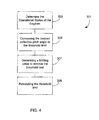
- Flight control system 201 determines the operational status 303 of the engines.
- Control system 202 in flight control system 201, compares 305 the desired collective pitch angle to that of the threshold limit of governor 203. If all engines are operable, then limiter 205 produces a baseline lower limit value. If any engine is inoperable or failed, then limiter 205 increases the baseline lower limit value as the threshold limit is exceeded.
- governor 203 communicates command data of symmetric collective pitch 209 to logic 215.
- Limiter 205 generates 307 a limiting value / signal configured to remove the threshold limit when combined. The threshold limit is set to zero. After a period of time, limiter 205 is configured to reinstate 309 the threshold limit by phases the limit back to normal.
- flight control system 201 may or may not reinstate the threshold limit. Reinstating the threshold limit may occur after touchdown or be configured to occur during flight after all engines become operable. Furthermore, it is understood that control system 202 is configured to function automatically. Additionally, system 201 may be retrofitted upon existing aircraft through one or more updates.
Landscapes
- Engineering & Computer Science (AREA)
- Mechanical Engineering (AREA)
- Aviation & Aerospace Engineering (AREA)
- Control Of Turbines (AREA)
- Feedback Control In General (AREA)
Claims (12)
- Ein Flugleitsystem (201) für einen Drehflügler (111) mit mindestens zwei Triebwerken (127), das Flugleitsystem ist dabei so gestaltet, dass es selektiv die vollständige Steuerung eines Kollektivverstellreglers des Drehflüglers durch den Piloten einschränken und zulassen kann, und bestehend aus:einem Leitsystem (202) für den Empfang von Informationen von einer Vielzahl von Sensoren und Geräten (122, 124, 125, 126, 127) zum Betriebszustand des Drehflüglers, wobei das Leitsystem aus Folgendem besteht:einem Regler (203) der so gestaltet ist, dass er die Geschwindigkeit eines Rotors im Fluggerät über den Kollektivverstellregler eines Rotorblattes einstellen kann; der Regler (203) verfügt dabei über einen Schwellenwert im Verhältnis zum maximalen Verstellwinkel des Rotorblattes; und ist gekennzeichnet durcheinen Begrenzer (205), der so gestaltet ist, dass er selektiv den Schwellenwert unter bestimmten Bedingungen und/oder spezifischen Manövern aufheben kann, um einem Piloten automatisch die volle Befehlsgewalt über den Kollektivverstellregler über dem Schwellenwert zu übertragen, indem der maximale Verstellwinkel des Rotorblattes vergrößert wird;wobei der Begrenzer (205) bei Versagen eines Triebwerkes (127) automatisch aktiviert wird und wenn die Kollektivblattverstellung über den Schwellenwert angehoben wird.
- Das Flugleitsystem in Anspruch 1, wobei der Begrenzer (205) deaktiviert wird, wenn die Triebwerke (127) in Betrieb sind.
- Das Flugleitsystem in Anspruch 2, wobei der Begrenzer (205) so gestaltet ist, dass er eine Basislinien-Untergrenze erzeugt, wenn er deaktiviert ist.
- Das Flugleitsystem eines der vorhergehenden Ansprüche, wobei Befehlssignale (123) vom Regler (205) und Befehlssignale vom Begrenzer zusammengefasst werden, um einen gesamten symmetrischen Kollektivblattverstellbefehl (213) für die Steuerung des Pitch des Rotorblattes zu erzeugen.
- Das Flugleitsystem in Anspruch 4, wobei:a) die Befehlssignale des Begrenzers (205) auf den Befehlssignalen des Reglers (203) basieren, der Regler (203) ist dabei so gestaltet, dass er selektiv mit dem Begrenzer (205) kommuniziert; oderb) die Befehlssignale des Begrenzers (205) sind so gestaltet, dass sie sich im Verhältnis zur Kollektivblattverstellposition einstellen, um den Schwellenwert des Reglers (203) aufzuheben.
- Das Flugleitsystem eines der vorhergehenden Ansprüche, wobei der Begrenzer (205) so gestaltet ist, dass er den Schwellenwert für ein ausgewähltes Zeitlimit aufheben kann, der Schwellenwert wird dabei bei Erreichen des Zeitlimits wieder eingesetzt.
- Ein Drehflügler (111), bestehend aus:einem ersten Triebwerk (127) und einem zweiten Triebwerk (127);einem Rotor und Rotorblättern, die individuell mit dem ersten Triebwerk und mit dem zweiten Triebwerk betrieben werden können; undeinem Flugleitsystem eines der vorhergehenden Ansprüche.
- Der Drehflügler in Anspruch 7, wobei:a) das Flugleitsystem (201) die Geschwindigkeit der Rotoren und die Funktionsfähigkeit des ersten Triebwerks (127) und des zweiten Triebwerks (127) überwacht; und/oderb) das erste Triebwerk (127) mit einer ersten Gondel (120a) und das zweite Triebwerk (127) mit einer zweiten Gondel (120b) verbunden ist, und wobei das Flugleitsystem (201) den Verstellwinkel der Rotoren in Abhängigkeit vom Winkel der Gondeln (125) einstellt; und/oder wobeic) der Schwellenwert für ein ausgewähltes Zeitlimit aufgehoben und der Schwellenwert nach Erreichen des Zeitlimits wieder eingesetzt wird.
- Ein Verfahren zur Verbesserung einer Sinkgeschwindigkeit beim Aufsetzen eines Drehflüglers (111) mit mindestens zwei Triebwerken (127), bestehend aus:der Bestimmung des Betriebszustandes eines ersten Triebwerks (127) und eines zweiten Triebwerks (127);dem Vergleich eines gewünschten Kollektivverstellwinkels mit dem eines Schwellenwerts eines Reglers (203); und gekennzeichnet durchdie Erzeugung eines Grenzwertes, der so gestaltet ist, dass er automatisch den Schwellenwert aufhebt, wenn der gewünschte Kollektivverstellwinkel den Schwellenwert überschreitet und das erste Triebwerk (127) nicht in Betrieb ist;wobei die Aufhebung des Schwellenwertes einem Piloten die volle Befehlsgewalt über den Kollektivverstellwinkel oberhalb des Schwellenwertes überträgt, indem der maximale Verstellwinkel des Rotorblattes vergrößert wird, um die Sinkgeschwindigkeit des Drehflüglers (111) beim Aufsetzen zu verringern.
- Das Verfahren in Anspruch 9, wobei der Schwellenwert vorübergehend für eine bestimmte Zeitdauer aufgehoben wird; und/oder wobei die Aufhebung des Schwellenwertes automatisch von einem Flugleitsystem (201) ausgeführt wird.
- Das Verfahren in Anspruch 9 oder 10, wobei der Grenzwert mit den Befehlssignalen im Regler (203) zusammengefasst wird, um den Schwellenwert herabzusetzen; und/oder wobei der Grenzwert vom Kollektivverstellwinkel abhängig ist.
- Das Verfahren in Anspruch 9, darüberhinaus bestehend aus:der Wiedereinsetzung des Schwellenwerts, sobald das erste Triebwerk (127) und das zweite Triebwerk (127) in Betrieb sind.
Applications Claiming Priority (1)
| Application Number | Priority Date | Filing Date | Title |
|---|---|---|---|
| US13/889,454 US9352831B2 (en) | 2013-05-08 | 2013-05-08 | Variable lower limit collective governor to improve recovery |
Publications (2)
| Publication Number | Publication Date |
|---|---|
| EP2801522A1 EP2801522A1 (de) | 2014-11-12 |
| EP2801522B1 true EP2801522B1 (de) | 2015-09-30 |
Family
ID=49585324
Family Applications (1)
| Application Number | Title | Priority Date | Filing Date |
|---|---|---|---|
| EP13193548.8A Active EP2801522B1 (de) | 2013-05-08 | 2013-11-19 | Variabler Kollektivverstell-Untergrenzregler für die Verbesserung der Rettung eines Luftfahrzeugs |
Country Status (4)
| Country | Link |
|---|---|
| US (1) | US9352831B2 (de) |
| EP (1) | EP2801522B1 (de) |
| BR (1) | BR102014010387A2 (de) |
| CA (2) | CA2972878C (de) |
Families Citing this family (2)
| Publication number | Priority date | Publication date | Assignee | Title |
|---|---|---|---|---|
| US10479491B2 (en) * | 2017-08-17 | 2019-11-19 | Textron Innovations Inc. | System and method for rotorcraft collective power hold |
| US11299286B2 (en) | 2019-05-15 | 2022-04-12 | Pratt & Whitney Canada Corp. | System and method for operating a multi-engine aircraft |
Family Cites Families (7)
| Publication number | Priority date | Publication date | Assignee | Title |
|---|---|---|---|---|
| US4355358A (en) | 1980-08-26 | 1982-10-19 | United Technologies Corporation | Adaptive aircraft actuator fault detection |
| DE3622031C2 (de) | 1986-07-02 | 1995-11-30 | United Technologies Corp | Steueranordnung für einen Hubschrauber zum automatischen Übergang in Autorotation |
| US5246188A (en) * | 1989-09-14 | 1993-09-21 | Koutsoupidis Theodore K | Wing turbines in conjuction with propulsion systems for aircraft and helicopters |
| DE60143027D1 (de) | 2000-05-16 | 2010-10-21 | Bell Helicopter Textron Inc | Taktiles signalisierungssystem für einen steuerknüppel und verfahren |
| US8195346B1 (en) * | 2009-01-21 | 2012-06-05 | Garmin International, Inc. | Envelope protection for mechanically-controlled aircraft |
| ITTO20090079U1 (it) | 2009-06-10 | 2010-12-11 | Agusta Spa | Sistema per la gestione ed il controllo della velocita' di uno o piu' rotori di un aeromobile atto a volare a punto fisso |
| US8651425B2 (en) | 2009-11-24 | 2014-02-18 | Merlin Technology Inc. | Emergency collective actuator and method for a helicopter |
-
2013
- 2013-05-08 US US13/889,454 patent/US9352831B2/en active Active
- 2013-11-19 EP EP13193548.8A patent/EP2801522B1/de active Active
-
2014
- 2014-03-11 CA CA2972878A patent/CA2972878C/en active Active
- 2014-03-11 CA CA2846150A patent/CA2846150C/en active Active
- 2014-04-30 BR BRBR102014010387-2A patent/BR102014010387A2/pt not_active Application Discontinuation
Also Published As
| Publication number | Publication date |
|---|---|
| EP2801522A1 (de) | 2014-11-12 |
| US20140332621A1 (en) | 2014-11-13 |
| US9352831B2 (en) | 2016-05-31 |
| CA2846150C (en) | 2017-08-22 |
| CA2846150A1 (en) | 2014-11-08 |
| CA2972878C (en) | 2020-08-25 |
| BR102014010387A2 (pt) | 2015-01-27 |
| CA2972878A1 (en) | 2014-11-08 |
Similar Documents
| Publication | Publication Date | Title |
|---|---|---|
| US11383829B2 (en) | System and method for automation of rotorcraft entry into autorotation and maintenance of stabilized autorotation | |
| EP2132089B1 (de) | Drehzahlregler für einen rotor mit einem variablen maximalen kollektiven blattwinkel und verfahren | |
| EP2810873B1 (de) | System und Verfahren zur Unterstützung der Rotordrehzahlsteuerung | |
| EP2774845B1 (de) | System und Verfahren zur adaptiven Regelung der Rotorgeschwindigkeit für optimale Leistung | |
| US11194349B2 (en) | Automated autorotation and pilot aiding system | |
| EP3444187B1 (de) | System und verfahren zur kollektiven leistungssperre für drehflügler | |
| EP1924492B1 (de) | Automatisches geschwindigkeitssteuersystem für luftfahrzeug | |
| US20200285232A1 (en) | Reverse Tactile Cue for Rotorcraft Rotor Overspeed Protection | |
| EP2818410B1 (de) | Drehmomentausgleichssteuerungssystem für Drehflügler | |
| US9567091B2 (en) | System and method for maximizing aircraft safe landing capability during one engine inoperative operation | |
| US20170190416A1 (en) | Rotorcraft state control | |
| EP2801522B1 (de) | Variabler Kollektivverstell-Untergrenzregler für die Verbesserung der Rettung eines Luftfahrzeugs | |
| EP3326911B1 (de) | Rotordrehzahlsteuerung mit vorwärtsgekoppeltem rotordrehzahlbefehl | |
| EP2813427B1 (de) | Auf Drehmoment basierendes Verfahren zur Begrenzung der Vertikalachsenzunahme | |
| EP3681800A1 (de) | Steuerung eines flugzeugs basierend auf der erfassung und verminderung von ermüdungszuständen und flugzeugschadensbedingungen | |
| US20240353867A1 (en) | Aircraft Emergency Descent System and Method |
Legal Events
| Date | Code | Title | Description |
|---|---|---|---|
| PUAI | Public reference made under article 153(3) epc to a published international application that has entered the european phase |
Free format text: ORIGINAL CODE: 0009012 |
|
| 17P | Request for examination filed |
Effective date: 20131119 |
|
| AK | Designated contracting states |
Kind code of ref document: A1 Designated state(s): AL AT BE BG CH CY CZ DE DK EE ES FI FR GB GR HR HU IE IS IT LI LT LU LV MC MK MT NL NO PL PT RO RS SE SI SK SM TR |
|
| AX | Request for extension of the european patent |
Extension state: BA ME |
|
| GRAP | Despatch of communication of intention to grant a patent |
Free format text: ORIGINAL CODE: EPIDOSNIGR1 |
|
| INTG | Intention to grant announced |
Effective date: 20150724 |
|
| GRAS | Grant fee paid |
Free format text: ORIGINAL CODE: EPIDOSNIGR3 |
|
| GRAA | (expected) grant |
Free format text: ORIGINAL CODE: 0009210 |
|
| AK | Designated contracting states |
Kind code of ref document: B1 Designated state(s): AL AT BE BG CH CY CZ DE DK EE ES FI FR GB GR HR HU IE IS IT LI LT LU LV MC MK MT NL NO PL PT RO RS SE SI SK SM TR |
|
| REG | Reference to a national code |
Ref country code: CH Ref legal event code: EP Ref country code: GB Ref legal event code: FG4D |
|
| REG | Reference to a national code |
Ref country code: AT Ref legal event code: REF Ref document number: 752220 Country of ref document: AT Kind code of ref document: T Effective date: 20151015 |
|
| REG | Reference to a national code |
Ref country code: IE Ref legal event code: FG4D |
|
| REG | Reference to a national code |
Ref country code: DE Ref legal event code: R096 Ref document number: 602013003293 Country of ref document: DE |
|
| REG | Reference to a national code |
Ref country code: FR Ref legal event code: PLFP Year of fee payment: 3 |
|
| PG25 | Lapsed in a contracting state [announced via postgrant information from national office to epo] |
Ref country code: LT Free format text: LAPSE BECAUSE OF FAILURE TO SUBMIT A TRANSLATION OF THE DESCRIPTION OR TO PAY THE FEE WITHIN THE PRESCRIBED TIME-LIMIT Effective date: 20150930 Ref country code: GR Free format text: LAPSE BECAUSE OF FAILURE TO SUBMIT A TRANSLATION OF THE DESCRIPTION OR TO PAY THE FEE WITHIN THE PRESCRIBED TIME-LIMIT Effective date: 20151231 Ref country code: LV Free format text: LAPSE BECAUSE OF FAILURE TO SUBMIT A TRANSLATION OF THE DESCRIPTION OR TO PAY THE FEE WITHIN THE PRESCRIBED TIME-LIMIT Effective date: 20150930 Ref country code: FI Free format text: LAPSE BECAUSE OF FAILURE TO SUBMIT A TRANSLATION OF THE DESCRIPTION OR TO PAY THE FEE WITHIN THE PRESCRIBED TIME-LIMIT Effective date: 20150930 Ref country code: NO Free format text: LAPSE BECAUSE OF FAILURE TO SUBMIT A TRANSLATION OF THE DESCRIPTION OR TO PAY THE FEE WITHIN THE PRESCRIBED TIME-LIMIT Effective date: 20151230 |
|
| REG | Reference to a national code |
Ref country code: NL Ref legal event code: MP Effective date: 20150930 |
|
| REG | Reference to a national code |
Ref country code: LT Ref legal event code: MG4D |
|
| REG | Reference to a national code |
Ref country code: AT Ref legal event code: MK05 Ref document number: 752220 Country of ref document: AT Kind code of ref document: T Effective date: 20150930 |
|
| PG25 | Lapsed in a contracting state [announced via postgrant information from national office to epo] |
Ref country code: RS Free format text: LAPSE BECAUSE OF FAILURE TO SUBMIT A TRANSLATION OF THE DESCRIPTION OR TO PAY THE FEE WITHIN THE PRESCRIBED TIME-LIMIT Effective date: 20150930 Ref country code: HR Free format text: LAPSE BECAUSE OF FAILURE TO SUBMIT A TRANSLATION OF THE DESCRIPTION OR TO PAY THE FEE WITHIN THE PRESCRIBED TIME-LIMIT Effective date: 20150930 Ref country code: SE Free format text: LAPSE BECAUSE OF FAILURE TO SUBMIT A TRANSLATION OF THE DESCRIPTION OR TO PAY THE FEE WITHIN THE PRESCRIBED TIME-LIMIT Effective date: 20150930 |
|
| PG25 | Lapsed in a contracting state [announced via postgrant information from national office to epo] |
Ref country code: SK Free format text: LAPSE BECAUSE OF FAILURE TO SUBMIT A TRANSLATION OF THE DESCRIPTION OR TO PAY THE FEE WITHIN THE PRESCRIBED TIME-LIMIT Effective date: 20150930 Ref country code: CZ Free format text: LAPSE BECAUSE OF FAILURE TO SUBMIT A TRANSLATION OF THE DESCRIPTION OR TO PAY THE FEE WITHIN THE PRESCRIBED TIME-LIMIT Effective date: 20150930 Ref country code: NL Free format text: LAPSE BECAUSE OF FAILURE TO SUBMIT A TRANSLATION OF THE DESCRIPTION OR TO PAY THE FEE WITHIN THE PRESCRIBED TIME-LIMIT Effective date: 20150930 Ref country code: ES Free format text: LAPSE BECAUSE OF FAILURE TO SUBMIT A TRANSLATION OF THE DESCRIPTION OR TO PAY THE FEE WITHIN THE PRESCRIBED TIME-LIMIT Effective date: 20150930 Ref country code: EE Free format text: LAPSE BECAUSE OF FAILURE TO SUBMIT A TRANSLATION OF THE DESCRIPTION OR TO PAY THE FEE WITHIN THE PRESCRIBED TIME-LIMIT Effective date: 20150930 Ref country code: IS Free format text: LAPSE BECAUSE OF FAILURE TO SUBMIT A TRANSLATION OF THE DESCRIPTION OR TO PAY THE FEE WITHIN THE PRESCRIBED TIME-LIMIT Effective date: 20160130 |
|
| PG25 | Lapsed in a contracting state [announced via postgrant information from national office to epo] |
Ref country code: PL Free format text: LAPSE BECAUSE OF FAILURE TO SUBMIT A TRANSLATION OF THE DESCRIPTION OR TO PAY THE FEE WITHIN THE PRESCRIBED TIME-LIMIT Effective date: 20150930 Ref country code: AT Free format text: LAPSE BECAUSE OF FAILURE TO SUBMIT A TRANSLATION OF THE DESCRIPTION OR TO PAY THE FEE WITHIN THE PRESCRIBED TIME-LIMIT Effective date: 20150930 Ref country code: PT Free format text: LAPSE BECAUSE OF FAILURE TO SUBMIT A TRANSLATION OF THE DESCRIPTION OR TO PAY THE FEE WITHIN THE PRESCRIBED TIME-LIMIT Effective date: 20160201 Ref country code: RO Free format text: LAPSE BECAUSE OF FAILURE TO SUBMIT A TRANSLATION OF THE DESCRIPTION OR TO PAY THE FEE WITHIN THE PRESCRIBED TIME-LIMIT Effective date: 20150930 |
|
| PG25 | Lapsed in a contracting state [announced via postgrant information from national office to epo] |
Ref country code: MC Free format text: LAPSE BECAUSE OF FAILURE TO SUBMIT A TRANSLATION OF THE DESCRIPTION OR TO PAY THE FEE WITHIN THE PRESCRIBED TIME-LIMIT Effective date: 20150930 Ref country code: LU Free format text: LAPSE BECAUSE OF FAILURE TO SUBMIT A TRANSLATION OF THE DESCRIPTION OR TO PAY THE FEE WITHIN THE PRESCRIBED TIME-LIMIT Effective date: 20151119 |
|
| REG | Reference to a national code |
Ref country code: DE Ref legal event code: R097 Ref document number: 602013003293 Country of ref document: DE |
|
| PLBE | No opposition filed within time limit |
Free format text: ORIGINAL CODE: 0009261 |
|
| STAA | Information on the status of an ep patent application or granted ep patent |
Free format text: STATUS: NO OPPOSITION FILED WITHIN TIME LIMIT |
|
| REG | Reference to a national code |
Ref country code: IE Ref legal event code: MM4A |
|
| PG25 | Lapsed in a contracting state [announced via postgrant information from national office to epo] |
Ref country code: DK Free format text: LAPSE BECAUSE OF FAILURE TO SUBMIT A TRANSLATION OF THE DESCRIPTION OR TO PAY THE FEE WITHIN THE PRESCRIBED TIME-LIMIT Effective date: 20150930 |
|
| 26N | No opposition filed |
Effective date: 20160701 |
|
| PG25 | Lapsed in a contracting state [announced via postgrant information from national office to epo] |
Ref country code: IE Free format text: LAPSE BECAUSE OF NON-PAYMENT OF DUE FEES Effective date: 20151119 |
|
| REG | Reference to a national code |
Ref country code: FR Ref legal event code: PLFP Year of fee payment: 4 |
|
| PG25 | Lapsed in a contracting state [announced via postgrant information from national office to epo] |
Ref country code: SI Free format text: LAPSE BECAUSE OF FAILURE TO SUBMIT A TRANSLATION OF THE DESCRIPTION OR TO PAY THE FEE WITHIN THE PRESCRIBED TIME-LIMIT Effective date: 20150930 |
|
| PG25 | Lapsed in a contracting state [announced via postgrant information from national office to epo] |
Ref country code: BE Free format text: LAPSE BECAUSE OF FAILURE TO SUBMIT A TRANSLATION OF THE DESCRIPTION OR TO PAY THE FEE WITHIN THE PRESCRIBED TIME-LIMIT Effective date: 20150930 |
|
| PG25 | Lapsed in a contracting state [announced via postgrant information from national office to epo] |
Ref country code: BG Free format text: LAPSE BECAUSE OF FAILURE TO SUBMIT A TRANSLATION OF THE DESCRIPTION OR TO PAY THE FEE WITHIN THE PRESCRIBED TIME-LIMIT Effective date: 20150930 |
|
| PG25 | Lapsed in a contracting state [announced via postgrant information from national office to epo] |
Ref country code: CY Free format text: LAPSE BECAUSE OF FAILURE TO SUBMIT A TRANSLATION OF THE DESCRIPTION OR TO PAY THE FEE WITHIN THE PRESCRIBED TIME-LIMIT Effective date: 20150930 Ref country code: HU Free format text: LAPSE BECAUSE OF FAILURE TO SUBMIT A TRANSLATION OF THE DESCRIPTION OR TO PAY THE FEE WITHIN THE PRESCRIBED TIME-LIMIT; INVALID AB INITIO Effective date: 20131119 |
|
| REG | Reference to a national code |
Ref country code: CH Ref legal event code: PL |
|
| PG25 | Lapsed in a contracting state [announced via postgrant information from national office to epo] |
Ref country code: CH Free format text: LAPSE BECAUSE OF NON-PAYMENT OF DUE FEES Effective date: 20161130 Ref country code: LI Free format text: LAPSE BECAUSE OF NON-PAYMENT OF DUE FEES Effective date: 20161130 |
|
| PG25 | Lapsed in a contracting state [announced via postgrant information from national office to epo] |
Ref country code: MT Free format text: LAPSE BECAUSE OF FAILURE TO SUBMIT A TRANSLATION OF THE DESCRIPTION OR TO PAY THE FEE WITHIN THE PRESCRIBED TIME-LIMIT Effective date: 20150930 |
|
| REG | Reference to a national code |
Ref country code: FR Ref legal event code: PLFP Year of fee payment: 5 |
|
| PG25 | Lapsed in a contracting state [announced via postgrant information from national office to epo] |
Ref country code: SM Free format text: LAPSE BECAUSE OF FAILURE TO SUBMIT A TRANSLATION OF THE DESCRIPTION OR TO PAY THE FEE WITHIN THE PRESCRIBED TIME-LIMIT Effective date: 20150930 |
|
| PG25 | Lapsed in a contracting state [announced via postgrant information from national office to epo] |
Ref country code: MK Free format text: LAPSE BECAUSE OF FAILURE TO SUBMIT A TRANSLATION OF THE DESCRIPTION OR TO PAY THE FEE WITHIN THE PRESCRIBED TIME-LIMIT Effective date: 20150930 |
|
| PG25 | Lapsed in a contracting state [announced via postgrant information from national office to epo] |
Ref country code: TR Free format text: LAPSE BECAUSE OF FAILURE TO SUBMIT A TRANSLATION OF THE DESCRIPTION OR TO PAY THE FEE WITHIN THE PRESCRIBED TIME-LIMIT Effective date: 20150930 Ref country code: AL Free format text: LAPSE BECAUSE OF FAILURE TO SUBMIT A TRANSLATION OF THE DESCRIPTION OR TO PAY THE FEE WITHIN THE PRESCRIBED TIME-LIMIT Effective date: 20150930 |
|
| P01 | Opt-out of the competence of the unified patent court (upc) registered |
Effective date: 20230602 |
|
| PGFP | Annual fee paid to national office [announced via postgrant information from national office to epo] |
Ref country code: DE Payment date: 20251128 Year of fee payment: 13 |
|
| PGFP | Annual fee paid to national office [announced via postgrant information from national office to epo] |
Ref country code: GB Payment date: 20251127 Year of fee payment: 13 |
|
| PGFP | Annual fee paid to national office [announced via postgrant information from national office to epo] |
Ref country code: IT Payment date: 20251119 Year of fee payment: 13 |
|
| PGFP | Annual fee paid to national office [announced via postgrant information from national office to epo] |
Ref country code: FR Payment date: 20251125 Year of fee payment: 13 |