EP3326911B1 - Rotordrehzahlsteuerung mit vorwärtsgekoppeltem rotordrehzahlbefehl - Google Patents
Rotordrehzahlsteuerung mit vorwärtsgekoppeltem rotordrehzahlbefehl Download PDFInfo
- Publication number
- EP3326911B1 EP3326911B1 EP17190849.4A EP17190849A EP3326911B1 EP 3326911 B1 EP3326911 B1 EP 3326911B1 EP 17190849 A EP17190849 A EP 17190849A EP 3326911 B1 EP3326911 B1 EP 3326911B1
- Authority
- EP
- European Patent Office
- Prior art keywords
- rotor speed
- command
- flight
- rotor
- change
- Prior art date
- Legal status (The legal status is an assumption and is not a legal conclusion. Google has not performed a legal analysis and makes no representation as to the accuracy of the status listed.)
- Active
Links
- 230000008859 change Effects 0.000 claims description 60
- 238000000034 method Methods 0.000 claims description 42
- 230000007423 decrease Effects 0.000 claims description 11
- 230000009467 reduction Effects 0.000 claims description 9
- 230000003247 decreasing effect Effects 0.000 claims description 3
- RZVHIXYEVGDQDX-UHFFFAOYSA-N 9,10-anthraquinone Chemical compound C1=CC=C2C(=O)C3=CC=CC=C3C(=O)C2=C1 RZVHIXYEVGDQDX-UHFFFAOYSA-N 0.000 description 10
- 230000008901 benefit Effects 0.000 description 7
- 238000010586 diagram Methods 0.000 description 6
- 230000000712 assembly Effects 0.000 description 4
- 238000000429 assembly Methods 0.000 description 4
- 230000000694 effects Effects 0.000 description 4
- 230000008569 process Effects 0.000 description 4
- 230000006872 improvement Effects 0.000 description 3
- 230000008878 coupling Effects 0.000 description 2
- 238000010168 coupling process Methods 0.000 description 2
- 238000005859 coupling reaction Methods 0.000 description 2
- 238000005516 engineering process Methods 0.000 description 2
- 230000004044 response Effects 0.000 description 2
- 230000007704 transition Effects 0.000 description 2
- 230000001133 acceleration Effects 0.000 description 1
- 230000004075 alteration Effects 0.000 description 1
- 238000003491 array Methods 0.000 description 1
- 238000004891 communication Methods 0.000 description 1
- 150000001875 compounds Chemical class 0.000 description 1
- 125000004122 cyclic group Chemical group 0.000 description 1
- 230000009977 dual effect Effects 0.000 description 1
- 230000006870 function Effects 0.000 description 1
- 230000003287 optical effect Effects 0.000 description 1
- 230000001141 propulsive effect Effects 0.000 description 1
- 238000006467 substitution reaction Methods 0.000 description 1
- 230000000153 supplemental effect Effects 0.000 description 1
- 230000000007 visual effect Effects 0.000 description 1
Images


Classifications
-
- B—PERFORMING OPERATIONS; TRANSPORTING
- B64—AIRCRAFT; AVIATION; COSMONAUTICS
- B64C—AEROPLANES; HELICOPTERS
- B64C13/00—Control systems or transmitting systems for actuating flying-control surfaces, lift-increasing flaps, air brakes, or spoilers
- B64C13/02—Initiating means
- B64C13/16—Initiating means actuated automatically, e.g. responsive to gust detectors
-
- B—PERFORMING OPERATIONS; TRANSPORTING
- B64—AIRCRAFT; AVIATION; COSMONAUTICS
- B64C—AEROPLANES; HELICOPTERS
- B64C27/00—Rotorcraft; Rotors peculiar thereto
- B64C27/54—Mechanisms for controlling blade adjustment or movement relative to rotor head, e.g. lag-lead movement
- B64C27/56—Mechanisms for controlling blade adjustment or movement relative to rotor head, e.g. lag-lead movement characterised by the control initiating means, e.g. manually actuated
- B64C27/57—Mechanisms for controlling blade adjustment or movement relative to rotor head, e.g. lag-lead movement characterised by the control initiating means, e.g. manually actuated automatic or condition responsive, e.g. responsive to rotor speed, torque or thrust
-
- B—PERFORMING OPERATIONS; TRANSPORTING
- B64—AIRCRAFT; AVIATION; COSMONAUTICS
- B64C—AEROPLANES; HELICOPTERS
- B64C13/00—Control systems or transmitting systems for actuating flying-control surfaces, lift-increasing flaps, air brakes, or spoilers
- B64C13/02—Initiating means
- B64C13/04—Initiating means actuated personally
-
- B—PERFORMING OPERATIONS; TRANSPORTING
- B64—AIRCRAFT; AVIATION; COSMONAUTICS
- B64C—AEROPLANES; HELICOPTERS
- B64C13/00—Control systems or transmitting systems for actuating flying-control surfaces, lift-increasing flaps, air brakes, or spoilers
- B64C13/24—Transmitting means
- B64C13/38—Transmitting means with power amplification
- B64C13/40—Transmitting means with power amplification using fluid pressure
-
- B—PERFORMING OPERATIONS; TRANSPORTING
- B64—AIRCRAFT; AVIATION; COSMONAUTICS
- B64C—AEROPLANES; HELICOPTERS
- B64C27/00—Rotorcraft; Rotors peculiar thereto
- B64C27/04—Helicopters
- B64C27/06—Helicopters with single rotor
-
- B—PERFORMING OPERATIONS; TRANSPORTING
- B64—AIRCRAFT; AVIATION; COSMONAUTICS
- B64D—EQUIPMENT FOR FITTING IN OR TO AIRCRAFT; FLIGHT SUITS; PARACHUTES; ARRANGEMENTS OR MOUNTING OF POWER PLANTS OR PROPULSION TRANSMISSIONS IN AIRCRAFT
- B64D31/00—Power plant control; Arrangement thereof
- B64D31/02—Initiating means
- B64D31/06—Initiating means actuated automatically
-
- G—PHYSICS
- G05—CONTROLLING; REGULATING
- G05D—SYSTEMS FOR CONTROLLING OR REGULATING NON-ELECTRIC VARIABLES
- G05D1/00—Control of position, course or altitude of land, water, air, or space vehicles, e.g. automatic pilot
- G05D1/08—Control of attitude, i.e. control of roll, pitch, or yaw
- G05D1/0808—Control of attitude, i.e. control of roll, pitch, or yaw specially adapted for aircraft
- G05D1/0858—Control of attitude, i.e. control of roll, pitch, or yaw specially adapted for aircraft specially adapted for vertical take-off of aircraft
Definitions
- the subject matter disclosed herein relates to controlling rotor speed, and more particularly, to rotor speed control using a feed-forward rotor speed reduction command.
- Certain aircraft e.g., helicopters
- helicopters utilize rotors to create propulsion and lift for flight.
- main rotor efficiency can be increased. This increases efficiency of the overall aircraft, enabling the aircraft to fly further, longer and/or faster hence more economically.
- EP2631172A2 discloses a system which is configured for automation of rotorcraft entry into autorotation.
- the system can provide a means to assist the flight crew of a rotorcraft in maintaining rotor speed following loss of engine power.
- the system can automatically adjust control positions, actuator positions or both to prevent excessive loss of rotor speed upon initial loss of engine power before the flight crew is able to react.
- the system uses model matching to provide axis de coupling and yaw anticipation. It includes pitch control initially to assist in preventing rotor deceleration, and it makes use of collective, pitch, roll and yaw trim functions to provide tactile cueing to the pilot to assist when the pilot is in the loop.
- the system can reduce workload by assisting the crew with controlling rotor speed and forward speed during stabilized autorotation.
- a computer-implemented method for feed-forward rotor speed command comprising: receiving, by a processing device, flight command indicative of a flight characteristic change of an aircraft comprising a rotor; generating, by the processing device, a load factor change based on the flight command; generating, by the processing device, a rotor speed change based on the load factor change; generating, by the processing device, a rotor speed command based on the rotor speed change to a flight controller to cause the aircraft to change a rotor speed of the rotor; and changing, by the processing device, the rotor speed of the rotor responsive to the rotor speed command.
- the change of the rotor speed represents a decrease to the rotor speed responsive to a decrease in the load factor.
- the flight command is responsive to a pilot command from a pilot of the aircraft.
- the pilot command is a command to maneuver the aircraft.
- the load factor change is further based on flight information.
- the flight information is a velocity
- the flight characteristics are selected from the group consisting of a pitch rate, a vertical rate, a pitch attitude, a roll attitude, and a velocity.
- a processing system for feed-forward rotor speed reduction using a feed-forward rotor speed reduction command comprising: a memory having computer readable instructions; and a processing device for executing the computer readable instructions to perform a method, the method comprising: receiving, by the processing device, first flight command indicative of a first flight characteristic change of an aircraft comprising a rotor; generating, by the processing device, a first load factor change based on the first flight command; generating, by the processing device, a first rotor speed change based on the first load factor change; generating, by the processing device, a first rotor speed command based on the first rotor speed change to a flight controller to cause the aircraft to change a rotor speed of the rotor to a first rotor speed; and increasing, by the processing device, the rotor speed of the rotor responsive to the rotor speed command.
- the method further comprises receiving, by the processing device, second flight command indicative of a second flight characteristic change of the aircraft.
- the method further comprises generating, by the processing device, a second load factor change based on the second flight command.
- the method further comprises generating, by the processing device, a second rotor speed change based on the second load factor change.
- the method further comprises generating, by the processing device, a second rotor speed command based on the second rotor speed change to the flight controller to cause the aircraft to change the rotor speed of the rotor to a second rotor speed.
- the method further comprises decreasing, by the processing device, the rotor speed of the rotor responsive to the rotor speed command.
- the first flight command is responsive to a first pilot command from a pilot of the aircraft
- the second flight command is responsive to a second pilot command from the pilot of the aircraft.
- Reducing rotor speed below nominal in high-speed operating environment provides benefits such as increased performance (e.g., increases in range, loiter times, maximum speed, reduced drag, etc.) and susceptibility (e.g., decreases in noise, etc.). For example, rotor speed may be reduced as much as 15% or even 20% below nominal. However, the reduction of rotor speed decreases aircraft maneuvering capabilities and may cause the aircraft to exceed certain performance constraints (e.g., tip clearance, hub loads, etc.).
- the present techniques introduce a rotor speed feed-forward command to provide for maneuverability and constraint avoidance.
- the feed-forward command represents a command fed into an engine controller for an aircraft to vary rotor speed based on a flight command (e.g., a pilot's command to maneuver the aircraft). This ensures that rotor speed is sufficient to enable the aircraft to continue flight through the maneuver.
- the rotor speed feed-forward command is based on pilot commands or from an autonomous system, such as commanded rates, attitudes, etc.
- the pilot commands are converted into a delta load factor command, which is related to a delta rotor speed command.
- the delta rotor speed command is added to a rotor speed reference command.
- tactile, aural, visual cues, etc. can be provided to pilot prior to and/or during transition.
- the present techniques provide benefits and advantages.
- the present techniques enable a lower rotor speed in steady-state flight while being able to transition to full rotor speed for maneuverability (e.g., load factor) and safety (e.g., tip clearance, hub moment, etc.).
- the rotor speed change can be directly related to pilotor autonomous system commands.
- the rotor reduction feed-forward command can provide system load (i.e., no waiting for load factor to build up).
- the rotor reduction feed-forward command also does not impact system stability. Incremental changes in rotor speed based on flight conditions are also possible.
- Example embodiments of the disclosure include or yield various technical features, technical effects, and/or improvements to technology.
- example embodiments of the disclosure provide the technical effect of increasing rotor speed for an aircraft responsive to a flight command, such as a pilot issuing a command to maneuver the aircraft. As a result, maneuverability of the aircraft is increased.
- the present techniques improve safety and operational efficiency, such as of an aircraft, by increasing rotor speed when needed.
- example embodiments of the disclosure constitute an improvement to existing flight control systems. It should be appreciated that the above examples of technical features, technical effects, and improvements to technology of example embodiments of the disclosure are merely illustrative and not exhaustive.
- FIG. 1 schematically illustrates an example of a rotary wing aircraft 10 having a main rotor assembly 12 according to examples of the present disclosure.
- the aircraft 10 includes an airframe 14 having an extending tail 16 which mounts a tail rotor system 18, such as an anti-torque system, a translational thrust system, a pusher propeller, a rotor propulsion system, and the like.
- the main rotor assembly 12 includes a plurality of rotor blade assemblies 22 mounted to a rotor hub 20.
- the main rotor assembly 12 is driven about an axis of rotation A through a main gearbox (illustrated schematically at T) by one or more engines E.
- helicopter configuration is illustrated and described in the disclosed embodiment, other configurations and/or machines, such as high speed compound rotary wing aircraft with supplemental translational thrust systems, dual contrarotating, coaxial rotor system aircraft, tilt-rotors and tilt-wing aircraft, and fixed wing aircraft, will also benefit from embodiments of the invention.
- a flight control system 70 is a fly-by-wire (FBW) control system.
- FBW fly-by-wire
- a FBW control system there is no direct mechanical coupling between a pilot's controls and movable components or control surfaces, such as rotor blade assemblies 20 or propeller blades 24 for example, of the aircraft 10 of FIG. 1 .
- a FBW control system includes a plurality of sensors 72 which can sense the position of controlled elements and generate electrical signals proportional to the sensed position.
- the sensors 72 may also be used directly and indirectly to provide a variety of aircraft state data to a flight control computer (FCC) 75.
- the FCC 75 may also receive pilot inputs 74 as control commands to control the lift, propulsive thrust, yaw, pitch, and roll forces and moments of the various control surfaces of the aircraft 10.
- the FCC 75 transmits signals to various subsystems of the aircraft 10, such as the main rotor system 12 and the tail rotor system 18.
- the FCC 75 can use reference values in the pilot inputs 74 for feed forward control to quickly respond to changes in the reference values and can perform feedback control to reject disturbances detected via the sensors 72.
- Pilot inputs 74 can be in the form of stick commands and /or beeper commands to set and incrementally adjust reference values for controllers.
- the pilot inputs 74 need not be directly provided by a human pilot, but may be driven by an automatic pilot, a remote control, a navigation-based control, or one or more outer control loops configured to produce one or more values used to pilot the aircraft 10.
- the main rotor system 12 can include an actuator control unit 50 configured to receive commands from the FCC 75 to control one or more actuators 55, such as a mechanical-hydraulic actuator, for the rotor blade assemblies 20 of FIGS. 1 and 2 .
- actuators 55 such as a mechanical-hydraulic actuator
- pilot inputs 74 including cyclic and /or collective commands may result in the actuator control unit 50 driving the one or more actuators 55 to adjust a swashplate assembly to control the rotor blade assemblies 20 of FIG. 1 .
- the FCC 75 can directly control the one or more actuators 55, and the actuator control unit 50 can be omitted.
- the tail rotor system 18 can include an actuator control unit 60 configured to receive commands from the FCC 75 to control one or more actuators 65, such as a mechanical-hydraulic actuator, associated with one or more propeller blades 24.
- actuators 65 such as a mechanical-hydraulic actuator
- pilot inputs 74 include a propeller pitch command for the actuator control unit 60 to drive the one or more actuators 65 for controlling the propeller blades FIG. 1 .
- the FCC 75 can directly control the one or more actuators 65, and the actuator control unit 60 can be omitted.
- the FCC 75 can also interface with an engine control system 85 including one or more electronic engine control units (EECUs) 80 to control the engines E.
- EECUs electronic engine control units
- Each EECU 80 may be a digital electronic control unit such as Full Authority Digital Engine Control (FADEC) electronically interconnected to a corresponding engine E.
- FADEC Full Authority Digital Engine Control
- Each engine E may include one or more instances of the EECU 80 to control engine output and performance.
- Engines E may be commanded in response to the pilot inputs 74, such as a throttle command.
- the FCC 75 includes a processing system 90 that applies models and control laws to augment commands.
- the processing system 90 includes processing circuitry 92, memory 94, and an input/output (I/O) interface 96.
- the processing circuitry 92 can be any type or combination of computer processors, such as a microprocessor, microcontroller, digital signal processor, application specific integrated circuit, programmable logic device, and /or field programmable gate array, and is generally referred to as central processing unit (CPU) 92.
- CPU central processing unit
- the memory 94 can include volatile and non-volatile memory, such as random access memory (RAM), read only memory (ROM), or other electronic, optical, magnetic, or any other computer readable storage medium onto which data and control logic as described herein are stored. Therefore, the memory 94 is a tangible storage medium where instructions executable by the processing circuitry 92 are embodied in a non-transitory form.
- the I/O interface 96 can include a variety of input interfaces, output interfaces, communication interfaces and support circuitry to acquire data from the sensors 72, pilot inputs 74, and other sources (not depicted) and may communicate with the control units 50, 60, 80, and other subsystems (not depicted).
- FIG. 3 illustrates a block diagram of the flight control system 70 of FIG. 2 according to examples of the present disclosure.
- the various components, modules, engines, etc. described regarding FIG. 3 may be implemented as instructions stored on a computer-readable storage medium, as hardware modules, as special-purpose hardware (e.g., application specific hardware, application specific integrated circuits (ASICs), as embedded controllers, hardwired circuitry, etc.), or as some combination or combinations of these.
- the engine(s) described herein may be a combination of hardware and programming.
- the programming may be processor executable instructions stored on a tangible memory, and the hardware may include a processing device for executing those instructions.
- a system memory can store program instructions that when executed by the processing device implement the engines described herein.
- Other engines may also be utilized to include other features and functionality described in other examples herein.
- the flight control system may include a load factor command module 302, a delta rotor speed command module 304, a rotor speed reference command module 306, and an engine controller module 308.
- the flight control system 70 may include dedicated hardware, such as one or more integrated circuits, Application Specific Integrated Circuits (ASICs), Application Specific Special Processors (ASSPs), Field Programmable Gate Arrays (FPGAs), or any combination of the foregoing examples of dedicated hardware, for performing the techniques described herein.
- ASICs Application Specific Integrated Circuits
- ASSPs Application Specific Special Processors
- FPGAs Field Programmable Gate Arrays
- the load factor command module 302 receives flight characteristics such as pitch rate, vertical rate, pitch attitude (thcta), roll attitude (phi), velocity, etc. from the flight controller computer (FCC) 75 of FIG. 2 or from other suitable sources.
- the load factor command module 302 determines a change in load factor (i.e., delta load factor) based on the received flight commands (i.e., pilot commands) and flight information. For example, when a pilot initiates a command to maneuver the aircraft, a flight command is sent to the load factor command module 302.
- the load factor may indicate pitch rate, velocity, vertical acceleration, roll attitude, and other flight factors.
- the delta rotor speed command module 304 receives the delta load factor from the load factor command module 302. Using the received delta load factor, the delta rotor speed command module 304 determines a change in rotor speed responsive to the change in load factor. For example, if the pilot initiates a maneuver (e.g., an increase in pitch rate, etc.) that needs an increase in rotor speed, the delta rotor speed command module 304 indicates that rotor speed should be increased. In some examples, the delta rotor speed command module 304 may also receive flight information such as velocity that may be used to determine the change in rotor speed. In another example, the pilot may issue a pilot command to change the rotor speed, such as increasing the rotor speed or decreasing the rotor speed. The change in rotor speed (i.e., delta rotor speed) is passed to the rotor speed reference command module.
- a maneuver e.g., an increase in pitch rate, etc.
- the delta rotor speed command module 304 indicates that
- the rotor speed reference command module 306 receives the delta rotor speed from the delta rotor speed command module 304 and generates a rotor speed command based on the current state of the rotor.
- the rotor speed command is sent to the engine controller module 308.
- the engine controller module 308 receives the rotor speed command from the rotor speed reference command module 306 and implements the change rotor speed (i.e., increase or decrease rotor speed) indicated by the rotor speed command.
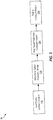
- FIG. 4 illustrates a flow diagram of a method 400 for feed-forward rotor speed reduction according to examples of the present disclosure.
- the method 400 may be performed, for example, by the flight control system 70 of FIGS. 2 and 3 .
- the method 400 includes receiving, by a processing device, flight command indicative of a change in a flight characteristic of an aircraft comprising a rotor.
- the method 400 includes generating, by the processing device, a load factor change based on the flight command.
- the method 400 includes generating, by the processing device, a rotor speed change based on the load factor change.
- the method 400 includes generating, by the processing device, a rotor speed command based on the rotor speed change to a flight controller to cause the aircraft to change a rotor speed of the rotor.
- the method 400 includes changing, by the processing device, the rotor speed of the rotor responsive to the rotor speed command.
- the change of the rotor speed represents an increase to the rotor speed responsive to an increase in the load factor. That is, when the load factor change is an increase, the rotor speed increases. In other examples, the change of the rotor speed represents a decrease to the rotor speed responsive to a decrease in the load factor. That is, when the load factor change is a decrease, the rotor speed decreases.
- Additional processes also may be include, and it should be understood that the processes depicted in FIG. 4 represent illustrations, and that other processes may be added or existing processes may be removed, modified, or rearranged without departing from the scope and spirit of the present disclosure.
Landscapes
- Engineering & Computer Science (AREA)
- Aviation & Aerospace Engineering (AREA)
- Automation & Control Theory (AREA)
- Physics & Mathematics (AREA)
- Mechanical Engineering (AREA)
- Fluid Mechanics (AREA)
- Radar, Positioning & Navigation (AREA)
- Remote Sensing (AREA)
- General Physics & Mathematics (AREA)
- Control Of Position, Course, Altitude, Or Attitude Of Moving Bodies (AREA)
Claims (15)
- Computerimplementiertes Verfahren zur vorwärtsgekoppelten Rotordrehzahlsteuerung, wobei das Verfahren Folgendes umfasst: Empfangen durch eine Verarbeitungseinrichtung (90) eines Flugbefehls, der eine Veränderung einer Flugeigenschaft eines Luftfahrzeugs (10), das einen Rotor (12) umfasst, angibt; Erzeugen durch die Verarbeitungseinrichtung (90) einer Veränderung des Lastvielfachen basierend auf dem Flugbefehl; Erzeugen durch die Verarbeitungseinrichtung (90) einer Veränderung der Rotordrehzahl basierend auf der Veränderung des Lastvielfachen; Erzeugen durch die Verarbeitungseinrichtung (90) eines Rotordrehzahlbefehls basierend auf der Veränderung der Rotordrehzahl an einen Flugregler (75), um zu bewirken, dass das Luftfahrzeug (10) eine Rotordrehzahl des Rotors (12) verändert; und Verändern durch die Verarbeitungseinrichtung (90) der Rotordrehzahl des Rotors (12) als Reaktion auf den Rotordrehzahlbefehl.
- Computerimplementiertes Verfahren nach Anspruch 1, wobei die Veränderung der Rotordrehzahl einen Anstieg der Rotordrehzahl als Reaktion auf einen Anstieg des Lastvielfachen darstellt.
- Computerimplementiertes Verfahren nach Anspruch 1 oder 2, wobei die Veränderung der Rotordrehzahl eine Abnahme der Rotordrehzahl als Reaktion auf eine Abnahme des Lastvielfachen darstellt.
- Computerimplementiertes Verfahren nach einem der Ansprüche 1-3, wobei der Flugbefehl eine Reaktion auf einen Pilotenbefehl von einem Piloten des Luftfahrzeugs ist.
- Computerimplementiertes Verfahren nach Anspruch 4, wobei der Pilotenbefehl ein Befehl zum Manövrieren des Luftfahrzeugs ist.
- Computerimplementiertes Verfahren nach einem der Ansprüche 1-5, wobei die Veränderung des Lastvielfachen ferner auf Fluginformationen basiert.
- Computerimplementiertes Verfahren nach Anspruch 6, wobei die Fluginformation eine Geschwindigkeit ist.
- Computerimplementiertes Verfahren nach einem der Ansprüche 1-7, wobei die Flugeigenschaften aus der Gruppe ausgewählt sind, die aus einer Anstellgeschwindigkeit, einer vertikalen Geschwindigkeit, einer Längsneigung, einer Querneigung und einer Geschwindigkeit besteht.
- Verarbeitungssystem zur vorwärtsgekoppelten Rotordrehzahlsteuerung unter Verwendung eines vorwärtsgekoppelten Rotordrehzahlverminderungsbefehls, wobei das System Folgendes umfasst: einen Speicher (94), der computerlesbare Anweisungen umfasst; und eine Verarbeitungseinrichtung (90), die konfiguriert ist, um die computerlesbaren Anweisungen auszuführen, um ein Verfahren durchzuführen, wobei das Verfahren Folgendes umfasst: Empfangen durch die Verarbeitungseinrichtung (90) eines ersten Flugbefehls, der eine erste Veränderung einer Flugeigenschaft eines Luftfahrzeugs (10), das einen Rotor (12) umfasst, angibt; Erzeugen durch die Verarbeitungseinrichtung (90) einer ersten Veränderung des Lastvielfachen basierend auf dem ersten Flugbefehl; Erzeugen durch die Verarbeitungseinrichtung (90) einer ersten Veränderung der Rotordrehzahl basierend auf der ersten Veränderung des Lastvielfachen; Erzeugen durch die Verarbeitungseinrichtung (90) eines ersten Rotordrehzahlbefehls basierend auf der ersten Veränderung der Rotordrehzahl an einen Flugregler (75), um zu bewirken, dass das Luftfahrzeug (10) eine Rotordrehzahl des Rotors (12) auf eine erste Rotordrehzahl verändert; und Erhöhen durch die Verarbeitungseinrichtung (90) der Rotordrehzahl des Rotors als Reaktion auf den Rotordrehzahlbefehl.
- Verarbeitungssystem nach Anspruch 9, wobei das Verfahren ferner das Empfangen durch die Verarbeitungseinrichtung eines zweiten Flugbefehls, der eine zweite Änderung einer Flugeigenschaft des Luftfahrzeugs angibt, umfasst.
- Verarbeitungssystem nach Anspruch 10, wobei das Verfahren ferner das Erzeugen durch die Verarbeitungseinrichtung einer zweiten Änderung des Lastvielfachen basierend auf dem zweiten Flugbefehl umfasst.
- Verarbeitungssystem nach Anspruch 11, wobei das Verfahren ferner das Erzeugen durch die Verarbeitungseinrichtung einer zweiten Änderung der Rotordrehzahl basierend auf der zweiten Änderung des Lastvielfachen umfasst.
- Verarbeitungssystem nach Anspruch 12, wobei das Verfahren ferner das Erzeugen durch die Verarbeitungseinrichtung eines zweiten Rotordrehzahlbefehls basierend auf der zweiten Änderung der Rotordrehzahl an den Flugregler, um zu bewirken, dass das Luftfahrzeug die Rotordrehzahl des Rotors auf eine zweite Rotordrehzahl ändert, umfasst.
- Verarbeitungssystem nach Anspruch 13, wobei das Verfahren ferner das Vermindern durch die Verarbeitungseinrichtung der Rotordrehzahl des Rotors als Reaktion auf den Rotordrehzahlbefehl umfasst.
- Verarbeitungssystem nach einem der Ansprüche 9=14, wobei der erste Flugbefehl eine Reaktion auf einen ersten Pilotenbefehl von einem Piloten des Luftfahrzeugs ist und der zweite Flugbefehl eine Reaktion auf einen zweiten Pilotenbefehl von dem Piloten des Luftfahrzeugs ist.
Applications Claiming Priority (1)
| Application Number | Priority Date | Filing Date | Title |
|---|---|---|---|
| US15/358,700 US10189559B2 (en) | 2016-11-22 | 2016-11-22 | Rotor speed control using a feed-forward rotor speed command |
Publications (2)
| Publication Number | Publication Date |
|---|---|
| EP3326911A1 EP3326911A1 (de) | 2018-05-30 |
| EP3326911B1 true EP3326911B1 (de) | 2019-07-10 |
Family
ID=59858646
Family Applications (1)
| Application Number | Title | Priority Date | Filing Date |
|---|---|---|---|
| EP17190849.4A Active EP3326911B1 (de) | 2016-11-22 | 2017-09-13 | Rotordrehzahlsteuerung mit vorwärtsgekoppeltem rotordrehzahlbefehl |
Country Status (2)
| Country | Link |
|---|---|
| US (1) | US10189559B2 (de) |
| EP (1) | EP3326911B1 (de) |
Families Citing this family (3)
| Publication number | Priority date | Publication date | Assignee | Title |
|---|---|---|---|---|
| US20170267338A1 (en) | 2014-10-01 | 2017-09-21 | Sikorsky Aircraft Corporation | Acoustic signature variation of aircraft utilizing a clutch |
| FR3075994B1 (fr) * | 2017-12-21 | 2023-11-24 | Airbus Operations Sas | Procede d'aide au pilotage d'un aeronef, permettant d'assurer la disponibilite d'un pilote automatique ou d'un regulateur de la poussee |
| CN112034871B (zh) * | 2020-08-25 | 2022-05-24 | 南京航空航天大学 | 一种可倾转多旋翼飞行器的全向控制方法 |
Family Cites Families (27)
| Publication number | Priority date | Publication date | Assignee | Title |
|---|---|---|---|---|
| GB2320829B (en) * | 1996-12-04 | 1998-10-21 | Lockheed Martin Tactical Sys | Method and system for predicting the motion e.g. of a ship or the like |
| US6189836B1 (en) * | 1998-09-25 | 2001-02-20 | Sikorsky Aircraft Corporation | Model-following control system using acceleration feedback |
| US6474603B1 (en) * | 2001-09-25 | 2002-11-05 | Sikorsky Aircraft Corporation | Flight control system for a hybrid aircraft in the pitch axis |
| US6592071B2 (en) * | 2001-09-25 | 2003-07-15 | Sikorsky Aircraft Corporation | Flight control system for a hybrid aircraft in the lift axis |
| US6879885B2 (en) | 2001-11-16 | 2005-04-12 | Goodrich Pump & Engine Control Systems, Inc. | Rotor torque predictor |
| US7900869B2 (en) * | 2004-05-06 | 2011-03-08 | Zf Friedrichshafen Ag | Helicopter rotor control system with individual blade control |
| FR2871438B1 (fr) * | 2004-06-10 | 2006-08-04 | Eurocopter France | Procede pour regler au moins un rotor deficient d'un giravion |
| US7438259B1 (en) * | 2006-08-16 | 2008-10-21 | Piasecki Aircraft Corporation | Compound aircraft control system and method |
| US7930074B2 (en) * | 2007-03-19 | 2011-04-19 | Sikorsky Aircraft Corporation | Vertical speed and flight path command module for displacement collective utilizing tactile cueing and tactile feedback |
| US9156546B2 (en) * | 2008-03-11 | 2015-10-13 | The Boeing Company | Active-inceptor tactile-cueing hands-off rate-limit |
| US8271151B2 (en) * | 2008-03-31 | 2012-09-18 | Sikorsky Aircraft Corporation | Flight control system for rotary wing aircraft |
| EP2261116B1 (de) * | 2009-06-09 | 2019-05-22 | Sikorsky Aircraft Corporation | Automatisches Trimmsystem für Fly-by-Wire-Flugzeuge mit einmaligen Trimmsteuerungen |
| ITTO20090079U1 (it) * | 2009-06-10 | 2010-12-11 | Agusta Spa | Sistema per la gestione ed il controllo della velocita' di uno o piu' rotori di un aeromobile atto a volare a punto fisso |
| EP2296064B1 (de) * | 2009-09-10 | 2019-04-24 | Sikorsky Aircraft Corporation | Leben verbesserndes Flugsteuerungssystem |
| EP2635942B1 (de) * | 2011-01-14 | 2015-06-17 | Bell Helicopter Textron Inc. | Flugsteuerungsrichtlinien für vertikale flugroutensteuerung |
| WO2012134460A1 (en) * | 2011-03-30 | 2012-10-04 | Bell Helicopter Textron Inc. | Flight control laws for constant vector flat turns |
| CA2974171C (en) * | 2011-07-15 | 2019-11-12 | Bell Helicopter Textron Inc. | Flight control laws for automatic hover hold |
| US9102400B2 (en) * | 2011-10-21 | 2015-08-11 | Sikorsky Aircraft Corporation | Methods and systems for providing constant-feel, multi-axis tactile cues |
| US10025320B2 (en) * | 2012-02-15 | 2018-07-17 | Sikorsky Aircraft Corporation | Control system for reconfigurable rotary wing aircraft |
| US9193450B2 (en) | 2012-02-24 | 2015-11-24 | Bell Helicopter Textron Inc. | System and method for automation of rotorcraft entry into autorotation and maintenance of stabilized autorotation |
| FR3000466B1 (fr) | 2012-12-27 | 2015-02-13 | Eurocopter France | Procede d'entrainement en rotation d'un rotor de giravion, par anticipation des besoins en couple entre deux consignes de vitesse de rotation du rotor |
| US9233753B2 (en) * | 2013-07-24 | 2016-01-12 | Sikorsky Aircraft Corporation | Helicopter rotor load reduction and tip clearance control |
| US9317042B2 (en) * | 2014-01-28 | 2016-04-19 | Sikorsky Aircraft Corporation | Pitch feedback control splitting for helicopters with redundant actuators |
| US9399511B2 (en) * | 2014-04-01 | 2016-07-26 | Bell Helicopter Textron Inc. | Rotorcraft fly-by-wire control laws |
| US9727059B2 (en) | 2014-06-23 | 2017-08-08 | Sikorsky Aircraft Corporation | Independent speed and attitude control for a rotary wing aircraft |
| US9758242B2 (en) * | 2015-02-04 | 2017-09-12 | Sikorsky Aircraft Corporation | Lift offset management and control systems for coaxial rotorcraft |
| US10488870B2 (en) | 2015-04-16 | 2019-11-26 | Sikorsky Aircraft Corporation | Gust alleviating control for a coaxial rotary wing aircraft |
-
2016
- 2016-11-22 US US15/358,700 patent/US10189559B2/en active Active
-
2017
- 2017-09-13 EP EP17190849.4A patent/EP3326911B1/de active Active
Non-Patent Citations (1)
| Title |
|---|
| None * |
Also Published As
| Publication number | Publication date |
|---|---|
| US20180141640A1 (en) | 2018-05-24 |
| EP3326911A1 (de) | 2018-05-30 |
| US10189559B2 (en) | 2019-01-29 |
Similar Documents
| Publication | Publication Date | Title |
|---|---|---|
| EP3445652B1 (de) | Kombinierte steigungsverstell- und vorwärtsschubsteuerung für unbemannte flugzeugsysteme | |
| US11383829B2 (en) | System and method for automation of rotorcraft entry into autorotation and maintenance of stabilized autorotation | |
| US9727059B2 (en) | Independent speed and attitude control for a rotary wing aircraft | |
| EP3201086B1 (de) | Leistungsverwaltung zwischen einem antrieb und koaxialem rotor eines hubschraubers | |
| US11194349B2 (en) | Automated autorotation and pilot aiding system | |
| EP3126231B1 (de) | Höhenruderlastreduzierungssteuerung für ein drehflügelflugzeug | |
| WO2016053991A1 (en) | Dual rotor, rotary wing aircraft | |
| EP3326911B1 (de) | Rotordrehzahlsteuerung mit vorwärtsgekoppeltem rotordrehzahlbefehl | |
| US10562609B2 (en) | High trim demand relief | |
| US20180022449A1 (en) | Rotor swashplate actuator position synchronization | |
| EP3640141B1 (de) | Umkehrschub in einem mehrmotorigen propellerflugzeug | |
| US9926076B2 (en) | Acceleration smoothing holding overall kinetic energy control | |
| EP3193230B1 (de) | Pilotenaktivierte trimmung für fly-by-wire-flugzeug | |
| US20230098878A1 (en) | Landing gear feedback control system for an aircraft | |
| EP3461741A1 (de) | Steuerungssysteme für koaxialen drehflügler |
Legal Events
| Date | Code | Title | Description |
|---|---|---|---|
| PUAI | Public reference made under article 153(3) epc to a published international application that has entered the european phase |
Free format text: ORIGINAL CODE: 0009012 |
|
| STAA | Information on the status of an ep patent application or granted ep patent |
Free format text: STATUS: THE APPLICATION HAS BEEN PUBLISHED |
|
| AK | Designated contracting states |
Kind code of ref document: A1 Designated state(s): AL AT BE BG CH CY CZ DE DK EE ES FI FR GB GR HR HU IE IS IT LI LT LU LV MC MK MT NL NO PL PT RO RS SE SI SK SM TR |
|
| AX | Request for extension of the european patent |
Extension state: BA ME |
|
| STAA | Information on the status of an ep patent application or granted ep patent |
Free format text: STATUS: REQUEST FOR EXAMINATION WAS MADE |
|
| 17P | Request for examination filed |
Effective date: 20181129 |
|
| RBV | Designated contracting states (corrected) |
Designated state(s): AL AT BE BG CH CY CZ DE DK EE ES FI FR GB GR HR HU IE IS IT LI LT LU LV MC MK MT NL NO PL PT RO RS SE SI SK SM TR |
|
| RIC1 | Information provided on ipc code assigned before grant |
Ipc: B64C 27/57 20060101AFI20181218BHEP Ipc: G05D 1/08 20060101ALI20181218BHEP |
|
| GRAP | Despatch of communication of intention to grant a patent |
Free format text: ORIGINAL CODE: EPIDOSNIGR1 |
|
| STAA | Information on the status of an ep patent application or granted ep patent |
Free format text: STATUS: GRANT OF PATENT IS INTENDED |
|
| INTG | Intention to grant announced |
Effective date: 20190130 |
|
| GRAS | Grant fee paid |
Free format text: ORIGINAL CODE: EPIDOSNIGR3 |
|
| GRAA | (expected) grant |
Free format text: ORIGINAL CODE: 0009210 |
|
| STAA | Information on the status of an ep patent application or granted ep patent |
Free format text: STATUS: THE PATENT HAS BEEN GRANTED |
|
| AK | Designated contracting states |
Kind code of ref document: B1 Designated state(s): AL AT BE BG CH CY CZ DE DK EE ES FI FR GB GR HR HU IE IS IT LI LT LU LV MC MK MT NL NO PL PT RO RS SE SI SK SM TR |
|
| REG | Reference to a national code |
Ref country code: GB Ref legal event code: FG4D |
|
| REG | Reference to a national code |
Ref country code: CH Ref legal event code: EP Ref country code: AT Ref legal event code: REF Ref document number: 1153314 Country of ref document: AT Kind code of ref document: T Effective date: 20190715 |
|
| REG | Reference to a national code |
Ref country code: DE Ref legal event code: R096 Ref document number: 602017005165 Country of ref document: DE |
|
| REG | Reference to a national code |
Ref country code: IE Ref legal event code: FG4D |
|
| REG | Reference to a national code |
Ref country code: NL Ref legal event code: MP Effective date: 20190710 |
|
| REG | Reference to a national code |
Ref country code: LT Ref legal event code: MG4D |
|
| REG | Reference to a national code |
Ref country code: AT Ref legal event code: MK05 Ref document number: 1153314 Country of ref document: AT Kind code of ref document: T Effective date: 20190710 |
|
| PG25 | Lapsed in a contracting state [announced via postgrant information from national office to epo] |
Ref country code: LT Free format text: LAPSE BECAUSE OF FAILURE TO SUBMIT A TRANSLATION OF THE DESCRIPTION OR TO PAY THE FEE WITHIN THE PRESCRIBED TIME-LIMIT Effective date: 20190710 Ref country code: NL Free format text: LAPSE BECAUSE OF FAILURE TO SUBMIT A TRANSLATION OF THE DESCRIPTION OR TO PAY THE FEE WITHIN THE PRESCRIBED TIME-LIMIT Effective date: 20190710 Ref country code: PT Free format text: LAPSE BECAUSE OF FAILURE TO SUBMIT A TRANSLATION OF THE DESCRIPTION OR TO PAY THE FEE WITHIN THE PRESCRIBED TIME-LIMIT Effective date: 20191111 Ref country code: FI Free format text: LAPSE BECAUSE OF FAILURE TO SUBMIT A TRANSLATION OF THE DESCRIPTION OR TO PAY THE FEE WITHIN THE PRESCRIBED TIME-LIMIT Effective date: 20190710 Ref country code: NO Free format text: LAPSE BECAUSE OF FAILURE TO SUBMIT A TRANSLATION OF THE DESCRIPTION OR TO PAY THE FEE WITHIN THE PRESCRIBED TIME-LIMIT Effective date: 20191010 Ref country code: BG Free format text: LAPSE BECAUSE OF FAILURE TO SUBMIT A TRANSLATION OF THE DESCRIPTION OR TO PAY THE FEE WITHIN THE PRESCRIBED TIME-LIMIT Effective date: 20191010 Ref country code: AT Free format text: LAPSE BECAUSE OF FAILURE TO SUBMIT A TRANSLATION OF THE DESCRIPTION OR TO PAY THE FEE WITHIN THE PRESCRIBED TIME-LIMIT Effective date: 20190710 Ref country code: SE Free format text: LAPSE BECAUSE OF FAILURE TO SUBMIT A TRANSLATION OF THE DESCRIPTION OR TO PAY THE FEE WITHIN THE PRESCRIBED TIME-LIMIT Effective date: 20190710 Ref country code: HR Free format text: LAPSE BECAUSE OF FAILURE TO SUBMIT A TRANSLATION OF THE DESCRIPTION OR TO PAY THE FEE WITHIN THE PRESCRIBED TIME-LIMIT Effective date: 20190710 |
|
| PG25 | Lapsed in a contracting state [announced via postgrant information from national office to epo] |
Ref country code: IS Free format text: LAPSE BECAUSE OF FAILURE TO SUBMIT A TRANSLATION OF THE DESCRIPTION OR TO PAY THE FEE WITHIN THE PRESCRIBED TIME-LIMIT Effective date: 20191110 Ref country code: LV Free format text: LAPSE BECAUSE OF FAILURE TO SUBMIT A TRANSLATION OF THE DESCRIPTION OR TO PAY THE FEE WITHIN THE PRESCRIBED TIME-LIMIT Effective date: 20190710 Ref country code: RS Free format text: LAPSE BECAUSE OF FAILURE TO SUBMIT A TRANSLATION OF THE DESCRIPTION OR TO PAY THE FEE WITHIN THE PRESCRIBED TIME-LIMIT Effective date: 20190710 Ref country code: GR Free format text: LAPSE BECAUSE OF FAILURE TO SUBMIT A TRANSLATION OF THE DESCRIPTION OR TO PAY THE FEE WITHIN THE PRESCRIBED TIME-LIMIT Effective date: 20191011 Ref country code: AL Free format text: LAPSE BECAUSE OF FAILURE TO SUBMIT A TRANSLATION OF THE DESCRIPTION OR TO PAY THE FEE WITHIN THE PRESCRIBED TIME-LIMIT Effective date: 20190710 Ref country code: ES Free format text: LAPSE BECAUSE OF FAILURE TO SUBMIT A TRANSLATION OF THE DESCRIPTION OR TO PAY THE FEE WITHIN THE PRESCRIBED TIME-LIMIT Effective date: 20190710 |
|
| PG25 | Lapsed in a contracting state [announced via postgrant information from national office to epo] |
Ref country code: TR Free format text: LAPSE BECAUSE OF FAILURE TO SUBMIT A TRANSLATION OF THE DESCRIPTION OR TO PAY THE FEE WITHIN THE PRESCRIBED TIME-LIMIT Effective date: 20190710 |
|
| PG25 | Lapsed in a contracting state [announced via postgrant information from national office to epo] |
Ref country code: DK Free format text: LAPSE BECAUSE OF FAILURE TO SUBMIT A TRANSLATION OF THE DESCRIPTION OR TO PAY THE FEE WITHIN THE PRESCRIBED TIME-LIMIT Effective date: 20190710 Ref country code: EE Free format text: LAPSE BECAUSE OF FAILURE TO SUBMIT A TRANSLATION OF THE DESCRIPTION OR TO PAY THE FEE WITHIN THE PRESCRIBED TIME-LIMIT Effective date: 20190710 Ref country code: PL Free format text: LAPSE BECAUSE OF FAILURE TO SUBMIT A TRANSLATION OF THE DESCRIPTION OR TO PAY THE FEE WITHIN THE PRESCRIBED TIME-LIMIT Effective date: 20190710 Ref country code: IT Free format text: LAPSE BECAUSE OF FAILURE TO SUBMIT A TRANSLATION OF THE DESCRIPTION OR TO PAY THE FEE WITHIN THE PRESCRIBED TIME-LIMIT Effective date: 20190710 Ref country code: RO Free format text: LAPSE BECAUSE OF FAILURE TO SUBMIT A TRANSLATION OF THE DESCRIPTION OR TO PAY THE FEE WITHIN THE PRESCRIBED TIME-LIMIT Effective date: 20190710 |
|
| PG25 | Lapsed in a contracting state [announced via postgrant information from national office to epo] |
Ref country code: SM Free format text: LAPSE BECAUSE OF FAILURE TO SUBMIT A TRANSLATION OF THE DESCRIPTION OR TO PAY THE FEE WITHIN THE PRESCRIBED TIME-LIMIT Effective date: 20190710 Ref country code: CZ Free format text: LAPSE BECAUSE OF FAILURE TO SUBMIT A TRANSLATION OF THE DESCRIPTION OR TO PAY THE FEE WITHIN THE PRESCRIBED TIME-LIMIT Effective date: 20190710 Ref country code: MC Free format text: LAPSE BECAUSE OF FAILURE TO SUBMIT A TRANSLATION OF THE DESCRIPTION OR TO PAY THE FEE WITHIN THE PRESCRIBED TIME-LIMIT Effective date: 20190710 Ref country code: SK Free format text: LAPSE BECAUSE OF FAILURE TO SUBMIT A TRANSLATION OF THE DESCRIPTION OR TO PAY THE FEE WITHIN THE PRESCRIBED TIME-LIMIT Effective date: 20190710 Ref country code: IS Free format text: LAPSE BECAUSE OF FAILURE TO SUBMIT A TRANSLATION OF THE DESCRIPTION OR TO PAY THE FEE WITHIN THE PRESCRIBED TIME-LIMIT Effective date: 20200224 |
|
| REG | Reference to a national code |
Ref country code: DE Ref legal event code: R097 Ref document number: 602017005165 Country of ref document: DE |
|
| PLBE | No opposition filed within time limit |
Free format text: ORIGINAL CODE: 0009261 |
|
| STAA | Information on the status of an ep patent application or granted ep patent |
Free format text: STATUS: NO OPPOSITION FILED WITHIN TIME LIMIT |
|
| PG2D | Information on lapse in contracting state deleted |
Ref country code: IS |
|
| PG25 | Lapsed in a contracting state [announced via postgrant information from national office to epo] |
Ref country code: IE Free format text: LAPSE BECAUSE OF NON-PAYMENT OF DUE FEES Effective date: 20190913 Ref country code: LU Free format text: LAPSE BECAUSE OF NON-PAYMENT OF DUE FEES Effective date: 20190913 |
|
| REG | Reference to a national code |
Ref country code: BE Ref legal event code: MM Effective date: 20190930 |
|
| 26N | No opposition filed |
Effective date: 20200603 |
|
| PG25 | Lapsed in a contracting state [announced via postgrant information from national office to epo] |
Ref country code: SI Free format text: LAPSE BECAUSE OF FAILURE TO SUBMIT A TRANSLATION OF THE DESCRIPTION OR TO PAY THE FEE WITHIN THE PRESCRIBED TIME-LIMIT Effective date: 20190710 Ref country code: BE Free format text: LAPSE BECAUSE OF NON-PAYMENT OF DUE FEES Effective date: 20190930 |
|
| REG | Reference to a national code |
Ref country code: CH Ref legal event code: PL |
|
| PG25 | Lapsed in a contracting state [announced via postgrant information from national office to epo] |
Ref country code: CY Free format text: LAPSE BECAUSE OF FAILURE TO SUBMIT A TRANSLATION OF THE DESCRIPTION OR TO PAY THE FEE WITHIN THE PRESCRIBED TIME-LIMIT Effective date: 20190710 |
|
| PG25 | Lapsed in a contracting state [announced via postgrant information from national office to epo] |
Ref country code: HU Free format text: LAPSE BECAUSE OF FAILURE TO SUBMIT A TRANSLATION OF THE DESCRIPTION OR TO PAY THE FEE WITHIN THE PRESCRIBED TIME-LIMIT; INVALID AB INITIO Effective date: 20170913 Ref country code: MT Free format text: LAPSE BECAUSE OF FAILURE TO SUBMIT A TRANSLATION OF THE DESCRIPTION OR TO PAY THE FEE WITHIN THE PRESCRIBED TIME-LIMIT Effective date: 20190710 |
|
| PG25 | Lapsed in a contracting state [announced via postgrant information from national office to epo] |
Ref country code: CH Free format text: LAPSE BECAUSE OF NON-PAYMENT OF DUE FEES Effective date: 20200930 Ref country code: LI Free format text: LAPSE BECAUSE OF NON-PAYMENT OF DUE FEES Effective date: 20200930 |
|
| PG25 | Lapsed in a contracting state [announced via postgrant information from national office to epo] |
Ref country code: MK Free format text: LAPSE BECAUSE OF FAILURE TO SUBMIT A TRANSLATION OF THE DESCRIPTION OR TO PAY THE FEE WITHIN THE PRESCRIBED TIME-LIMIT Effective date: 20190710 |
|
| P01 | Opt-out of the competence of the unified patent court (upc) registered |
Effective date: 20230523 |
|
| PGFP | Annual fee paid to national office [announced via postgrant information from national office to epo] |
Ref country code: GB Payment date: 20230927 Year of fee payment: 7 |
|
| PGFP | Annual fee paid to national office [announced via postgrant information from national office to epo] |
Ref country code: FR Payment date: 20230925 Year of fee payment: 7 Ref country code: DE Payment date: 20230927 Year of fee payment: 7 |