EP2801434A2 - Procédé destiné à relier plusieurs éléments de réservoir et dispositif de réservoir - Google Patents
Procédé destiné à relier plusieurs éléments de réservoir et dispositif de réservoir Download PDFInfo
- Publication number
- EP2801434A2 EP2801434A2 EP20140165585 EP14165585A EP2801434A2 EP 2801434 A2 EP2801434 A2 EP 2801434A2 EP 20140165585 EP20140165585 EP 20140165585 EP 14165585 A EP14165585 A EP 14165585A EP 2801434 A2 EP2801434 A2 EP 2801434A2
- Authority
- EP
- European Patent Office
- Prior art keywords
- elements
- tank
- adapter device
- adapter
- connection
- Prior art date
- Legal status (The legal status is an assumption and is not a legal conclusion. Google has not performed a legal analysis and makes no representation as to the accuracy of the status listed.)
- Withdrawn
Links
Images


Classifications
-
- B—PERFORMING OPERATIONS; TRANSPORTING
- B23—MACHINE TOOLS; METAL-WORKING NOT OTHERWISE PROVIDED FOR
- B23K—SOLDERING OR UNSOLDERING; WELDING; CLADDING OR PLATING BY SOLDERING OR WELDING; CUTTING BY APPLYING HEAT LOCALLY, e.g. FLAME CUTTING; WORKING BY LASER BEAM
- B23K33/00—Specially-profiled edge portions of workpieces for making soldering or welding connections; Filling the seams formed thereby
- B23K33/002—Crimping or bending the workpieces at the joining area
-
- B—PERFORMING OPERATIONS; TRANSPORTING
- B23—MACHINE TOOLS; METAL-WORKING NOT OTHERWISE PROVIDED FOR
- B23K—SOLDERING OR UNSOLDERING; WELDING; CLADDING OR PLATING BY SOLDERING OR WELDING; CUTTING BY APPLYING HEAT LOCALLY, e.g. FLAME CUTTING; WORKING BY LASER BEAM
- B23K31/00—Processes relevant to this subclass, specially adapted for particular articles or purposes, but not covered by any single one of main groups B23K1/00 - B23K28/00
- B23K31/02—Processes relevant to this subclass, specially adapted for particular articles or purposes, but not covered by any single one of main groups B23K1/00 - B23K28/00 relating to soldering or welding
-
- B—PERFORMING OPERATIONS; TRANSPORTING
- B60—VEHICLES IN GENERAL
- B60K—ARRANGEMENT OR MOUNTING OF PROPULSION UNITS OR OF TRANSMISSIONS IN VEHICLES; ARRANGEMENT OR MOUNTING OF PLURAL DIVERSE PRIME-MOVERS IN VEHICLES; AUXILIARY DRIVES FOR VEHICLES; INSTRUMENTATION OR DASHBOARDS FOR VEHICLES; ARRANGEMENTS IN CONNECTION WITH COOLING, AIR INTAKE, GAS EXHAUST OR FUEL SUPPLY OF PROPULSION UNITS IN VEHICLES
- B60K15/00—Arrangement in connection with fuel supply of combustion engines or other fuel consuming energy converters, e.g. fuel cells; Mounting or construction of fuel tanks
- B60K15/03—Fuel tanks
- B60K15/063—Arrangement of tanks
- B60K15/067—Mounting of tanks
- B60K15/07—Mounting of tanks of gas tanks
-
- F—MECHANICAL ENGINEERING; LIGHTING; HEATING; WEAPONS; BLASTING
- F17—STORING OR DISTRIBUTING GASES OR LIQUIDS
- F17C—VESSELS FOR CONTAINING OR STORING COMPRESSED, LIQUEFIED OR SOLIDIFIED GASES; FIXED-CAPACITY GAS-HOLDERS; FILLING VESSELS WITH, OR DISCHARGING FROM VESSELS, COMPRESSED, LIQUEFIED, OR SOLIDIFIED GASES
- F17C1/00—Pressure vessels, e.g. gas cylinder, gas tank, replaceable cartridge
-
- B—PERFORMING OPERATIONS; TRANSPORTING
- B23—MACHINE TOOLS; METAL-WORKING NOT OTHERWISE PROVIDED FOR
- B23K—SOLDERING OR UNSOLDERING; WELDING; CLADDING OR PLATING BY SOLDERING OR WELDING; CUTTING BY APPLYING HEAT LOCALLY, e.g. FLAME CUTTING; WORKING BY LASER BEAM
- B23K2101/00—Articles made by soldering, welding or cutting
- B23K2101/04—Tubular or hollow articles
- B23K2101/12—Vessels
-
- F—MECHANICAL ENGINEERING; LIGHTING; HEATING; WEAPONS; BLASTING
- F02—COMBUSTION ENGINES; HOT-GAS OR COMBUSTION-PRODUCT ENGINE PLANTS
- F02M—SUPPLYING COMBUSTION ENGINES IN GENERAL WITH COMBUSTIBLE MIXTURES OR CONSTITUENTS THEREOF
- F02M21/00—Apparatus for supplying engines with non-liquid fuels, e.g. gaseous fuels stored in liquid form
- F02M21/02—Apparatus for supplying engines with non-liquid fuels, e.g. gaseous fuels stored in liquid form for gaseous fuels
- F02M21/0203—Apparatus for supplying engines with non-liquid fuels, e.g. gaseous fuels stored in liquid form for gaseous fuels characterised by the type of gaseous fuel
- F02M21/0215—Mixtures of gaseous fuels; Natural gas; Biogas; Mine gas; Landfill gas
-
- F—MECHANICAL ENGINEERING; LIGHTING; HEATING; WEAPONS; BLASTING
- F02—COMBUSTION ENGINES; HOT-GAS OR COMBUSTION-PRODUCT ENGINE PLANTS
- F02M—SUPPLYING COMBUSTION ENGINES IN GENERAL WITH COMBUSTIBLE MIXTURES OR CONSTITUENTS THEREOF
- F02M21/00—Apparatus for supplying engines with non-liquid fuels, e.g. gaseous fuels stored in liquid form
- F02M21/02—Apparatus for supplying engines with non-liquid fuels, e.g. gaseous fuels stored in liquid form for gaseous fuels
- F02M21/0218—Details on the gaseous fuel supply system, e.g. tanks, valves, pipes, pumps, rails, injectors or mixers
- F02M21/0221—Fuel storage reservoirs, e.g. cryogenic tanks
-
- F—MECHANICAL ENGINEERING; LIGHTING; HEATING; WEAPONS; BLASTING
- F17—STORING OR DISTRIBUTING GASES OR LIQUIDS
- F17C—VESSELS FOR CONTAINING OR STORING COMPRESSED, LIQUEFIED OR SOLIDIFIED GASES; FIXED-CAPACITY GAS-HOLDERS; FILLING VESSELS WITH, OR DISCHARGING FROM VESSELS, COMPRESSED, LIQUEFIED, OR SOLIDIFIED GASES
- F17C2201/00—Vessel construction, in particular geometry, arrangement or size
- F17C2201/01—Shape
- F17C2201/0104—Shape cylindrical
- F17C2201/0109—Shape cylindrical with exteriorly curved end-piece
-
- F—MECHANICAL ENGINEERING; LIGHTING; HEATING; WEAPONS; BLASTING
- F17—STORING OR DISTRIBUTING GASES OR LIQUIDS
- F17C—VESSELS FOR CONTAINING OR STORING COMPRESSED, LIQUEFIED OR SOLIDIFIED GASES; FIXED-CAPACITY GAS-HOLDERS; FILLING VESSELS WITH, OR DISCHARGING FROM VESSELS, COMPRESSED, LIQUEFIED, OR SOLIDIFIED GASES
- F17C2201/00—Vessel construction, in particular geometry, arrangement or size
- F17C2201/05—Size
- F17C2201/056—Small (<1 m3)
-
- F—MECHANICAL ENGINEERING; LIGHTING; HEATING; WEAPONS; BLASTING
- F17—STORING OR DISTRIBUTING GASES OR LIQUIDS
- F17C—VESSELS FOR CONTAINING OR STORING COMPRESSED, LIQUEFIED OR SOLIDIFIED GASES; FIXED-CAPACITY GAS-HOLDERS; FILLING VESSELS WITH, OR DISCHARGING FROM VESSELS, COMPRESSED, LIQUEFIED, OR SOLIDIFIED GASES
- F17C2201/00—Vessel construction, in particular geometry, arrangement or size
- F17C2201/05—Size
- F17C2201/058—Size portable (<30 l)
-
- F—MECHANICAL ENGINEERING; LIGHTING; HEATING; WEAPONS; BLASTING
- F17—STORING OR DISTRIBUTING GASES OR LIQUIDS
- F17C—VESSELS FOR CONTAINING OR STORING COMPRESSED, LIQUEFIED OR SOLIDIFIED GASES; FIXED-CAPACITY GAS-HOLDERS; FILLING VESSELS WITH, OR DISCHARGING FROM VESSELS, COMPRESSED, LIQUEFIED, OR SOLIDIFIED GASES
- F17C2203/00—Vessel construction, in particular walls or details thereof
- F17C2203/06—Materials for walls or layers thereof; Properties or structures of walls or their materials
- F17C2203/0602—Wall structures; Special features thereof
- F17C2203/0612—Wall structures
- F17C2203/0614—Single wall
- F17C2203/0617—Single wall with one layer
-
- F—MECHANICAL ENGINEERING; LIGHTING; HEATING; WEAPONS; BLASTING
- F17—STORING OR DISTRIBUTING GASES OR LIQUIDS
- F17C—VESSELS FOR CONTAINING OR STORING COMPRESSED, LIQUEFIED OR SOLIDIFIED GASES; FIXED-CAPACITY GAS-HOLDERS; FILLING VESSELS WITH, OR DISCHARGING FROM VESSELS, COMPRESSED, LIQUEFIED, OR SOLIDIFIED GASES
- F17C2205/00—Vessel construction, in particular mounting arrangements, attachments or identifications means
- F17C2205/01—Mounting arrangements
- F17C2205/0123—Mounting arrangements characterised by number of vessels
- F17C2205/013—Two or more vessels
- F17C2205/0134—Two or more vessels characterised by the presence of fluid connection between vessels
- F17C2205/0142—Two or more vessels characterised by the presence of fluid connection between vessels bundled in parallel
-
- F—MECHANICAL ENGINEERING; LIGHTING; HEATING; WEAPONS; BLASTING
- F17—STORING OR DISTRIBUTING GASES OR LIQUIDS
- F17C—VESSELS FOR CONTAINING OR STORING COMPRESSED, LIQUEFIED OR SOLIDIFIED GASES; FIXED-CAPACITY GAS-HOLDERS; FILLING VESSELS WITH, OR DISCHARGING FROM VESSELS, COMPRESSED, LIQUEFIED, OR SOLIDIFIED GASES
- F17C2209/00—Vessel construction, in particular methods of manufacturing
- F17C2209/22—Assembling processes
-
- F—MECHANICAL ENGINEERING; LIGHTING; HEATING; WEAPONS; BLASTING
- F17—STORING OR DISTRIBUTING GASES OR LIQUIDS
- F17C—VESSELS FOR CONTAINING OR STORING COMPRESSED, LIQUEFIED OR SOLIDIFIED GASES; FIXED-CAPACITY GAS-HOLDERS; FILLING VESSELS WITH, OR DISCHARGING FROM VESSELS, COMPRESSED, LIQUEFIED, OR SOLIDIFIED GASES
- F17C2209/00—Vessel construction, in particular methods of manufacturing
- F17C2209/23—Manufacturing of particular parts or at special locations
- F17C2209/234—Manufacturing of particular parts or at special locations of closing end pieces, e.g. caps
-
- F—MECHANICAL ENGINEERING; LIGHTING; HEATING; WEAPONS; BLASTING
- F17—STORING OR DISTRIBUTING GASES OR LIQUIDS
- F17C—VESSELS FOR CONTAINING OR STORING COMPRESSED, LIQUEFIED OR SOLIDIFIED GASES; FIXED-CAPACITY GAS-HOLDERS; FILLING VESSELS WITH, OR DISCHARGING FROM VESSELS, COMPRESSED, LIQUEFIED, OR SOLIDIFIED GASES
- F17C2221/00—Handled fluid, in particular type of fluid
- F17C2221/03—Mixtures
- F17C2221/032—Hydrocarbons
- F17C2221/033—Methane, e.g. natural gas, CNG, LNG, GNL, GNC, PLNG
-
- F—MECHANICAL ENGINEERING; LIGHTING; HEATING; WEAPONS; BLASTING
- F17—STORING OR DISTRIBUTING GASES OR LIQUIDS
- F17C—VESSELS FOR CONTAINING OR STORING COMPRESSED, LIQUEFIED OR SOLIDIFIED GASES; FIXED-CAPACITY GAS-HOLDERS; FILLING VESSELS WITH, OR DISCHARGING FROM VESSELS, COMPRESSED, LIQUEFIED, OR SOLIDIFIED GASES
- F17C2223/00—Handled fluid before transfer, i.e. state of fluid when stored in the vessel or before transfer from the vessel
- F17C2223/01—Handled fluid before transfer, i.e. state of fluid when stored in the vessel or before transfer from the vessel characterised by the phase
- F17C2223/0107—Single phase
- F17C2223/0123—Single phase gaseous, e.g. CNG, GNC
-
- F—MECHANICAL ENGINEERING; LIGHTING; HEATING; WEAPONS; BLASTING
- F17—STORING OR DISTRIBUTING GASES OR LIQUIDS
- F17C—VESSELS FOR CONTAINING OR STORING COMPRESSED, LIQUEFIED OR SOLIDIFIED GASES; FIXED-CAPACITY GAS-HOLDERS; FILLING VESSELS WITH, OR DISCHARGING FROM VESSELS, COMPRESSED, LIQUEFIED, OR SOLIDIFIED GASES
- F17C2223/00—Handled fluid before transfer, i.e. state of fluid when stored in the vessel or before transfer from the vessel
- F17C2223/03—Handled fluid before transfer, i.e. state of fluid when stored in the vessel or before transfer from the vessel characterised by the pressure level
- F17C2223/035—High pressure (>10 bar)
-
- F—MECHANICAL ENGINEERING; LIGHTING; HEATING; WEAPONS; BLASTING
- F17—STORING OR DISTRIBUTING GASES OR LIQUIDS
- F17C—VESSELS FOR CONTAINING OR STORING COMPRESSED, LIQUEFIED OR SOLIDIFIED GASES; FIXED-CAPACITY GAS-HOLDERS; FILLING VESSELS WITH, OR DISCHARGING FROM VESSELS, COMPRESSED, LIQUEFIED, OR SOLIDIFIED GASES
- F17C2223/00—Handled fluid before transfer, i.e. state of fluid when stored in the vessel or before transfer from the vessel
- F17C2223/03—Handled fluid before transfer, i.e. state of fluid when stored in the vessel or before transfer from the vessel characterised by the pressure level
- F17C2223/036—Very high pressure (>80 bar)
-
- F—MECHANICAL ENGINEERING; LIGHTING; HEATING; WEAPONS; BLASTING
- F17—STORING OR DISTRIBUTING GASES OR LIQUIDS
- F17C—VESSELS FOR CONTAINING OR STORING COMPRESSED, LIQUEFIED OR SOLIDIFIED GASES; FIXED-CAPACITY GAS-HOLDERS; FILLING VESSELS WITH, OR DISCHARGING FROM VESSELS, COMPRESSED, LIQUEFIED, OR SOLIDIFIED GASES
- F17C2270/00—Applications
- F17C2270/01—Applications for fluid transport or storage
- F17C2270/0165—Applications for fluid transport or storage on the road
- F17C2270/0168—Applications for fluid transport or storage on the road by vehicles
- F17C2270/0178—Cars
-
- F—MECHANICAL ENGINEERING; LIGHTING; HEATING; WEAPONS; BLASTING
- F17—STORING OR DISTRIBUTING GASES OR LIQUIDS
- F17C—VESSELS FOR CONTAINING OR STORING COMPRESSED, LIQUEFIED OR SOLIDIFIED GASES; FIXED-CAPACITY GAS-HOLDERS; FILLING VESSELS WITH, OR DISCHARGING FROM VESSELS, COMPRESSED, LIQUEFIED, OR SOLIDIFIED GASES
- F17C2270/00—Applications
- F17C2270/07—Applications for household use
- F17C2270/0754—Fire extinguishers
Definitions
- the present invention relates to a method for connecting a plurality of tank elements.
- Tank elements can be connected to each other, for example by means of valves and pipes.
- the object of the present invention is to stably connect a plurality of tank elements to one another and thus to provide, in particular, a safe and stable tank device.
- a plurality of tank elements are arranged by means of connecting elements and a cohesive and / or positive connection to an adapter device, a particularly stable connection between the tank elements and thus a secure and stable tank device can be provided.
- connection elements may be inserted into openings of the adapter device and then connected to the adapter device.
- connection elements are welded to the adapter device.
- connection elements are connected to the adapter device by an expansion forming method.
- connection elements are connected to the adapter device by an electromagnetic pulse forming method.
- an electromagnetic pulse shaping method in particular by means of the electromagnetic pulse-forming technology (EMPT), it is preferably possible to make a material connection of metallic components without supplying thermal energy.
- EMPT electromagnetic pulse-forming technology
- a targeted acceleration, in particular a targeted expansion, of at least one of the components to be connected is generated by means of a pulsed, high-energy magnetic field.
- a cohesive connection of the components by the construction of a metallic bond.
- connection element is inserted into each one opening of the adapter device.
- An expansion element of a forming device is preferably introduced into an interior of the connection element, so that the expansion element in an overlapping region of the adapter device and the connection element with respect to a direction of insertion in the radial direction of both the attachment element as is also surrounded by the adapter device.
- the connection element is preferably expanded and thereby fixed to the adapter device.
- the expansion element is in particular an expansion coil, in particular for carrying out the electromagnetic pulse forming process.
- two adapter plates of the adapter device are each provided on one side with a plurality of tank elements and that the adapter plates are connected to each other at their sides facing away from the tank elements.
- tank elements are arranged on opposite sides of the adapter device.
- the hollow cylindrical portion, the end cap and the attachment member are fluid-tightly interconnected.
- the hollow cylindrical section, the end cap and / or the connecting element are preferably surrounded, in particular braided and / or wrapped, after they have been joined together with a fiber material. It can be provided that the fiber material is provided with a matrix material, in particular wetted and / or soaked.
- the tank elements are preferably arranged side by side in such a way that the center axes of hollow cylindrical sections of the tank elements are substantially parallel to one another.
- the interconnected by means of the adapter device tank elements preferably form winding elements of a winding core, which are wrapped by means of a winding device with at least one fiber.
- the at least one fiber is preferably passed between and / or around the tank elements between the tank elements.
- a tank device can be provided by means of the method according to the invention.
- the present invention further relates to a tank device comprising a plurality of tank elements.
- the invention is in this respect the task of providing a tank device, which comprises a plurality of stable interconnected tank elements and thus is designed to be safe and stable.
- a tank device comprising a plurality of tank elements, a plurality of connection elements and an adapter device for fluidly effective connection of interior spaces of the tank elements, wherein the connection elements each form one of two end caps of a tank element and by means of a cohesive and / or positive connection to the adapter device are arranged.
- the tank device according to the invention preferably has one or more of the features and / or advantages described in connection with the method according to the invention.
- connection elements fluidly connect the interior spaces of the tank elements with connection channels of the adapter device.
- connection elements have a varying material thickness, wherein the material thickness at one of the adapter device facing the end of the connection elements is greater or stronger than the material thickness at one of the adapter device opposite end of the connection elements.
- the hollow-cylindrical sections comprise a fluid-tight inner shell and a fiber-reinforced outer shell.
- the interior spaces of all tank elements are preferably connected to each other in a fluid-efficient manner.
- the tank elements are preferably fixed relative to each other and positioned against rotation.
- the tank elements are optimally positioned and / or aligned in particular for carrying out a subsequent winding process.
- connection elements are preferably formed from an aluminum alloy. In this way, the electromagnetic pulse forming process is particularly efficient feasible.
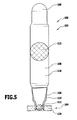
- each attachment element in which it is arranged on the adapter device, is tapered and in particular has a small inner cross-sectional area compared to the inner cross-sectional area of the hollow-cylindrical portion.
- the inner cross-sectional area in this region of the attachment element is at most approximately one quarter of the inner cross-sectional area of the hollow-cylindrical section.
- connection element Due to a reduced internal cross-sectional area of the connection element in the region of the connection to the adapter device, a force acting in this area due to the pressure in the tank elements can preferably be reduced. Furthermore, preferably holding forces can be reduced. Finally, this can also be achieved a reduction of voltages within the adapter device.
- the tank device is particularly suitable for storage of natural gas in the automotive industry, for use in fire extinguishing systems and / or for the transport of fluids of any kind, in particular for the transport of pressurized gases.
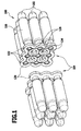
- FIG. 1 to 5 illustrated embodiment of a designated as a whole with 100 tank device comprises a plurality, for example, 18, tank elements 102, which are interconnected by means of an adapter device 104.
- the individual tank elements 102 each comprise a central hollow-cylindrical section 106, which is provided on both sides with an end cap 108.
- One of the end caps 108 is formed as a connection element 110.
- the tank element 102 can be fixed to the adapter device 104.
- the connecting element 110 is designed to be tapered so that an inner cross-sectional area 112 at an end of the connecting element 110 facing away from the hollow-cylindrical section 106 is smaller than an inner cross-sectional area 112 in the region of the hollow-cylindrical section 106.
- the tank elements 102 in particular the hollow cylindrical sections 106 of the tank elements 102, preferably comprise a fluid-tight inner shell 114, which is surrounded by a fiber-reinforced outer shell 116, for example to reinforce it.
- the fluid-tight inner shell 114 and the end caps 108 are welded together to form an interior 118 of each tank element 102 to surround fluid-tight.
- the interior 118 of the tank element 102 is preferably only accessible through the connection element 110.
- the adapter device 104 comprises two adapter plates 120, which each comprise nine openings 122 for receiving the connection elements 110.
- connecting channels 124 are provided, by means of which the openings 122 are fluidly connected to each other.
- connection channels 124 are formed, for example, by a groove 126 in the surface of the adapter plate 120 facing away from the tank elements 102.
- connection elements 110 For stable connection of the connection elements 110 with an adapter plate 120, the connection elements 110 are provided with an increasing in the direction of the adapter plate 120 material thickness.
- each attachment element 110 is thus significantly greater, in particular in a region in which the attachment element 110 is materially connected to an adapter plate 120, than at an end of the attachment element 110 facing the hollow cylindrical section 106.
- tank elements 102 do not all have the same cross-sectional shape.
- tank elements 102 are provided, in particular to be able to fill an available space with the largest possible tank volume.
- the tank elements 102 are aligned with respect to center axes 128 of the hollow cylindrical portions 106 parallel to each other and substantially matrix-shaped arranged, so that in particular columns 130 and rows 132 of tank elements 102 are formed.
- tank elements 102 when nine tank elements 102 are arranged next to one another, four tank elements 102 designed as corner elements 134, four tank elements 102 designed as edge elements 136 and one tank element 102 designed as an interior element 138 are provided.
- Corner elements 134 are tank elements 102 which form both an end of a column 130 and an end of a row 132.
- Edge elements 136 are tank elements 102 which form one end of a row 132 or one end of a column 130.
- the inner element 138 forms neither an end of a column 130 nor an end of a row 132.
- the tank elements 102 are spaced apart from each other, so that between the tank elements 102, a channel-like gap 140 is formed.
- At least one fiber can thus be passed between the tank elements 102.
- the tank elements 102 can thus be wrapped by means of at least one fiber and fixed particularly stable relative to each other.
- the gaps 140 are thus fiber channels 142.
- the tank elements 102 in particular form winding elements 144 of a winding core 146, on which the at least one fiber can be wound up by means of at least one winding device (not shown).
- the adapter plates 120 of the adapter device 104 are manufactured, in particular by the openings 122 and formed as grooves 126 connecting channels 124 are introduced.
- the tank elements 102 are introduced with the connection elements 110 in the openings 122 of the adapter plates 120 and fixed by attaching a welded joint between the connection elements 110 and the adapter plates 120.
- Each adapter plate 120 is then provided on each side with nine tank elements 102 each.
- the adapter plates 120 are arranged with their tank elements 102 facing away from each other sides and fluid-tightly interconnected.
- the tank elements 102 are additionally wound around at least one fiber by means of a winding device (not shown).
- the fibrous structure thus obtained is preferably infiltrated with a hardening matrix material. In this way, a particularly stable fiber reinforced housing for all tank elements 102 can be provided.
- a single fiber, a fiber bundle, a thread, a roving, a fiber strand and / or a multifilament yarn can be provided as fiber for the wrapping of the tank elements 102.
- FIG. 6 to 8 illustrated alternative embodiment of a tank device 100 differs from that in the Fig. 1 to 5 illustrated embodiment essentially in that the connection between the connecting elements 110 and the adapter plates 120 is not made by a welding process.
- connection elements 110 are positively and / or materially connected to the adapter plates 120 connectable.
- the operation of the forming device 148 is based in particular on the electromagnetic pulse forming technology (EMPT).
- EMPT electromagnetic pulse forming technology
- the forming device 148 comprises an expansion element 150, which can be inserted in an insertion direction 151 into the openings 122 of the adapter plates 120.
- the expansion element 150 is designed in particular as an expansion coil.
- the connecting element 110 likewise introduced into the opening 122 can be expanded at least in sections and connected in a form-locking and / or material-locking manner to the adapter plate 120.
- the expansion element 150 can be arranged, in particular, in an interior 152 of the connection element 110, this interior 152 comprising an overlapping region 154 in which the expansion element 150 is surrounded at least in sections by both the connection element 110 and the adapter plate 120 in a radial direction with respect to the insertion direction 151 is.
- the adapter plate 120 is provided in particular with projections 156 and / or depressions 158, so that a particularly stable connection is produced by the forming of the connecting element 110 and the resulting molding of the connecting element 110 to the shape of the opening 122 of the adapter plate 120 (please refer Fig. 8 ).
- both the openings 122 and the connection elements 110 may have different cross-sections 160.
- each cross section 160 it is possible for each cross section 160 to produce a reliable cohesive and / or positive connection between the connection elements 110 and the adapter plates 120.
- a (not shown) sealing element between the respective connecting element 110 and the adapter plate 120 may be provided.
- the expansion element 150 is removed from the opening 122 counter to the insertion direction 151 and is available again for connecting a further tank element 102 with the same or another adapter plate 120.
Landscapes
- Engineering & Computer Science (AREA)
- Mechanical Engineering (AREA)
- General Engineering & Computer Science (AREA)
- Life Sciences & Earth Sciences (AREA)
- Sustainable Development (AREA)
- Sustainable Energy (AREA)
- Chemical & Material Sciences (AREA)
- Combustion & Propulsion (AREA)
- Transportation (AREA)
- Filling Or Discharging Of Gas Storage Vessels (AREA)
- Supply Devices, Intensifiers, Converters, And Telemotors (AREA)
Applications Claiming Priority (1)
| Application Number | Priority Date | Filing Date | Title |
|---|---|---|---|
| DE201310208467 DE102013208467A1 (de) | 2013-05-08 | 2013-05-08 | Verfahren zum Verbinden mehrerer Tankelemente und Tankvorrichtung |
Publications (2)
| Publication Number | Publication Date |
|---|---|
| EP2801434A2 true EP2801434A2 (fr) | 2014-11-12 |
| EP2801434A3 EP2801434A3 (fr) | 2015-06-17 |
Family
ID=50513143
Family Applications (1)
| Application Number | Title | Priority Date | Filing Date |
|---|---|---|---|
| EP14165585.2A Withdrawn EP2801434A3 (fr) | 2013-05-08 | 2014-04-23 | Procédé destiné à relier plusieurs éléments de réservoir et dispositif de réservoir |
Country Status (2)
| Country | Link |
|---|---|
| EP (1) | EP2801434A3 (fr) |
| DE (1) | DE102013208467A1 (fr) |
Families Citing this family (1)
| Publication number | Priority date | Publication date | Assignee | Title |
|---|---|---|---|---|
| KR102681377B1 (ko) * | 2019-10-08 | 2024-07-03 | 현대자동차주식회사 | 차량용 가스연료 저장장치 |
Family Cites Families (8)
| Publication number | Priority date | Publication date | Assignee | Title |
|---|---|---|---|---|
| US5347816A (en) * | 1992-07-31 | 1994-09-20 | University Of Chicago | Variable pressure thermal insulating jacket |
| DE19812904C2 (de) * | 1998-03-18 | 2000-02-03 | Mannesmann Ag | Vorrichtung zum Speichern von Druckgas |
| JP2000193194A (ja) * | 1998-12-25 | 2000-07-14 | Mitsubishi Chemicals Corp | 耐圧容器及びその製造方法 |
| JP3627670B2 (ja) * | 2001-05-16 | 2005-03-09 | 日産自動車株式会社 | 高圧ガス容器の取付構造 |
| DE10129632C1 (de) * | 2001-06-20 | 2003-04-24 | Paul Kunkel | Behälterartige hydraulische und pneumatische Bauelemente |
| DE202006004434U1 (de) * | 2006-03-21 | 2006-06-08 | Otto Fuchs Kg | Kraftstoffbehälteranordnung zum Speichern druckbeaufschlagter Gase für ein Kraftfahrzeug |
| ITMC20060074A1 (it) * | 2006-06-13 | 2007-12-14 | Sida Engineering Srl | Serbatoio multi-celle, perfezionato, per gas in pressione. |
| US7651554B2 (en) * | 2007-10-26 | 2010-01-26 | Ovonic Hydrogen Systems Llc | Hydrogen storage system |
-
2013
- 2013-05-08 DE DE201310208467 patent/DE102013208467A1/de not_active Withdrawn
-
2014
- 2014-04-23 EP EP14165585.2A patent/EP2801434A3/fr not_active Withdrawn
Non-Patent Citations (1)
| Title |
|---|
| None |
Also Published As
| Publication number | Publication date |
|---|---|
| EP2801434A3 (fr) | 2015-06-17 |
| DE102013208467A1 (de) | 2014-11-13 |
Similar Documents
| Publication | Publication Date | Title |
|---|---|---|
| DE2448160C2 (fr) | ||
| DE102020105454B4 (de) | Verfahren zur Herstellung eines Mikrokanalbündel-Wärmetauschers und Verwendung eines Mikrokanalbündel-Wärmetauschers | |
| WO2009003207A1 (fr) | Ensemble pour relier un élément allongé à un autre composant | |
| EP3010705B1 (fr) | Carter de cylindre en construction mixte et légère et procédé permettant la réalisation dudit carter de cylindre | |
| EP2929211B1 (fr) | Amortisseur de chocs pour véhicule avec bride de raccordement à un tube de module externe | |
| DE19933256A1 (de) | Anschlussstutzen und Gehäuse, insbesondere Kraftstoffhochdruckspeicher, mit vorgespannt angeschweißtem Anschlussstutzen für ein Kraftstoffeinspritzsystem für Brennkraftmaschinen | |
| EP3413414B1 (fr) | Manchon d'étanchéité pour un faisceau de tubes | |
| DE102008004435A1 (de) | Abgaskomponente | |
| EP3142843B1 (fr) | Procédé de production d'un tube d'amortisseur à partir d'un matériau composite renforcé par des fibres pour amortisseur de vibrations | |
| EP2801434A2 (fr) | Procédé destiné à relier plusieurs éléments de réservoir et dispositif de réservoir | |
| EP3523154B1 (fr) | Élément de renforcement pour un contenant à liquide destiné à un véhicule automobile et contenant à liquide pour un véhicule automobile comprenant un élément de renforcement | |
| DE10343250B4 (de) | Verfahren zur Herstellung eines Druckbehälters zur Speicherung eines gasförmigen Mediums und Druckbehälter | |
| EP3228768A1 (fr) | Profilé | |
| AT514227B1 (de) | Verfahren zum Verbinden mehrerer Tankelemente und Tankvorrichtung | |
| EP1423601B1 (fr) | Accumulateur de carburant haute pression destine a un systeme d'injection a accumulateur | |
| DE102017201420A1 (de) | Tank, insbesondere Drucktank, insbesondere Wasserstoff-Drucktank | |
| WO2020173690A1 (fr) | Composant de structure pour un cadre de châssis et procédé pour sa fabrication | |
| EP0406596A1 (fr) | Procédé pour la fabrication de renforcements en forme de collets ou de brides sur des corps composites renforcés de fibres, notamment sur des tuyaux composites enroulés renforcés de fibres | |
| DE102019206435A1 (de) | Mehrpunktlenker für ein Fahrwerk eines Fahrzeugs | |
| DE102018106925A1 (de) | Verfahren zum Herstellen eines Drucktanks | |
| DE102017003024A1 (de) | Abschlusselement zur Krafteinleitung in ein vorgefertigtes Faserkunststoffverbundrohr | |
| EP4437264B1 (fr) | Rail pour un système de réservoir d'hydrogène sous pression sous forme d'un profilé extrudé | |
| DE102015111759A1 (de) | Kraftstoffverteiler | |
| EP3245049A1 (fr) | Élément d'insertion pour tube renforcé par des fibres | |
| EP1795806A2 (fr) | Chambre chaude |
Legal Events
| Date | Code | Title | Description |
|---|---|---|---|
| PUAI | Public reference made under article 153(3) epc to a published international application that has entered the european phase |
Free format text: ORIGINAL CODE: 0009012 |
|
| 17P | Request for examination filed |
Effective date: 20140423 |
|
| AK | Designated contracting states |
Kind code of ref document: A2 Designated state(s): AL AT BE BG CH CY CZ DE DK EE ES FI FR GB GR HR HU IE IS IT LI LT LU LV MC MK MT NL NO PL PT RO RS SE SI SK SM TR |
|
| AX | Request for extension of the european patent |
Extension state: BA ME |
|
| PUAL | Search report despatched |
Free format text: ORIGINAL CODE: 0009013 |
|
| AK | Designated contracting states |
Kind code of ref document: A3 Designated state(s): AL AT BE BG CH CY CZ DE DK EE ES FI FR GB GR HR HU IE IS IT LI LT LU LV MC MK MT NL NO PL PT RO RS SE SI SK SM TR |
|
| AX | Request for extension of the european patent |
Extension state: BA ME |
|
| RIC1 | Information provided on ipc code assigned before grant |
Ipc: B23K 33/00 20060101AFI20150513BHEP Ipc: B23K 31/02 20060101ALI20150513BHEP Ipc: B60K 15/07 20060101ALI20150513BHEP Ipc: F16L 23/026 20060101ALI20150513BHEP Ipc: F17C 1/00 20060101ALI20150513BHEP Ipc: F16L 41/03 20060101ALI20150513BHEP Ipc: F02M 21/02 20060101ALI20150513BHEP |
|
| STAA | Information on the status of an ep patent application or granted ep patent |
Free format text: STATUS: THE APPLICATION HAS BEEN WITHDRAWN |
|
| 18W | Application withdrawn |
Effective date: 20150630 |