EP2800959B1 - Assembly, intercalated between a torque tool and a fastening element, for measuring torques and tightening angles - Google Patents
Assembly, intercalated between a torque tool and a fastening element, for measuring torques and tightening angles Download PDFInfo
- Publication number
- EP2800959B1 EP2800959B1 EP11795003.0A EP11795003A EP2800959B1 EP 2800959 B1 EP2800959 B1 EP 2800959B1 EP 11795003 A EP11795003 A EP 11795003A EP 2800959 B1 EP2800959 B1 EP 2800959B1
- Authority
- EP
- European Patent Office
- Prior art keywords
- subassembly
- parameter
- strain
- socket
- torque
- Prior art date
- Legal status (The legal status is an assumption and is not a legal conclusion. Google has not performed a legal analysis and makes no representation as to the accuracy of the status listed.)
- Active
Links
Images




Classifications
-
- G—PHYSICS
- G01—MEASURING; TESTING
- G01L—MEASURING FORCE, STRESS, TORQUE, WORK, MECHANICAL POWER, MECHANICAL EFFICIENCY, OR FLUID PRESSURE
- G01L5/00—Apparatus for, or methods of, measuring force, work, mechanical power, or torque, specially adapted for specific purposes
- G01L5/24—Apparatus for, or methods of, measuring force, work, mechanical power, or torque, specially adapted for specific purposes for determining value of torque or twisting moment for tightening a nut or other member which is similarly stressed
-
- B—PERFORMING OPERATIONS; TRANSPORTING
- B25—HAND TOOLS; PORTABLE POWER-DRIVEN TOOLS; MANIPULATORS
- B25B—TOOLS OR BENCH DEVICES NOT OTHERWISE PROVIDED FOR, FOR FASTENING, CONNECTING, DISENGAGING, OR HOLDING
- B25B13/00—Spanners; Wrenches
- B25B13/02—Spanners; Wrenches with rigid jaws
- B25B13/06—Spanners; Wrenches with rigid jaws of socket type
-
- B—PERFORMING OPERATIONS; TRANSPORTING
- B25—HAND TOOLS; PORTABLE POWER-DRIVEN TOOLS; MANIPULATORS
- B25B—TOOLS OR BENCH DEVICES NOT OTHERWISE PROVIDED FOR, FOR FASTENING, CONNECTING, DISENGAGING, OR HOLDING
- B25B23/00—Details of, or accessories for, spanners, wrenches, screwdrivers
- B25B23/14—Arrangement of torque limiters or torque indicators in wrenches or screwdrivers
- B25B23/142—Arrangement of torque limiters or torque indicators in wrenches or screwdrivers specially adapted for hand operated wrenches or screwdrivers
- B25B23/1422—Arrangement of torque limiters or torque indicators in wrenches or screwdrivers specially adapted for hand operated wrenches or screwdrivers torque indicators or adjustable torque limiters
- B25B23/1425—Arrangement of torque limiters or torque indicators in wrenches or screwdrivers specially adapted for hand operated wrenches or screwdrivers torque indicators or adjustable torque limiters by electrical means
Definitions
- the present invention relates in general to sockets for interconnecting torque tools and fastening elements and, more specifically, to an assembly intercalated between a torque tool and a fastening element, for measuring torques and tightening angles.
- the required tension is determined by applied torque, which is previously established by engineering calculus. According to this method, the torque, or torsional load is often measured using strain gauge(s). According to another method, the required tension is measured by an angular displacement of a fastener. Attempts have been made to develop an apparatus, using various ultrasonic techniques, for directly measuring fasteners tension. For example. United States Patent No. 5.058.439 granted on October 22, 1991 to Carpenter for a --UT Socket Assembly" discloses an ultrasonic transducer socket assembly, used with a torque tool, for simultaneously tightening a bolt and measuring bolt load.
- a pole adaptor rigidly attached to a driving socket for engaging and driving a bolt has a stationary cylinder mounted therein.
- a second cylinder, rotatable and slidably received in the stationary cylinder, has an ultrasonic transducer pivotally mounted at one end that contacts the bolt to be tightened, when the socket is engaged with the bolt.
- the rotating cylinder and transducer are rotated approximately 180 degrees during engagement of the socket and bolt to smear an even couplant layer between the bolt and transducer to assure consistent measurements of bolt load during tightening a socket assembly including a ultrasonic transducer capable of measuring the bolt tension.
- the foregoing apparatus has several disadvantages. Among them, the fact that the apparatus incorporates complex mechanical features which can negatively affect the precision of the measurements, increases the manufacturing cost, reduces the reliability, and greatly increases the length and weight of the socket which in many applications is impractical.
- Patent document published US 2011/0120233 A1 discloses an assembly to be intercalated between a torque tool and a fastening element, for measuring torques and angular displacements of fasteners comprising a socket subassembly having an unitary elongated shaft, including at one extremity a first engaging cavity, at an opposite extremity, a strain transducer subassembly, for measuring torsional strains on said socket subassembly, a circular cover attached to said socket subassembly and an electronic subassembly for converting said torsional strains on said socket subassembly to standard torque values and for determining tightening angular displacements; said electronic subassembly being interconnected to said strain transducer subassembly and mounted on said circular cover to face said strain transducer subassembly; said circular cover subassembly comprising a first and second semicircular segments; said first semi-circular segment incorporating a radial protrusion
- an assembly intercalated between a torque tool and a fastening element, for measuring torques and tightening angles, generally referenced as 10, comprises in combination;
- Processing unit A includes:
- the user will mount assembly 10, intercalated between a torque tool (not shown) and a fastening element (also not shown), for measuring torques and tightening angles, onto torque tool, such as a powered torque tool (not shown), by inserting the driving tool shaft of the latter into first engaging cavity 110, wherein may be retained by a locking pin.
- torque tool such as a powered torque tool (not shown)
- the user will then engage the fastener assembly 19 (not shown) with assembly 10, respectively its second engaging cavity 120.
- the user by using display 410 and keypad 415 , can select and modify the ultimate torque and angular displacement values, which are displayed in standard engineering units, by incrementing or decrementing the values via the keypad pushbuttons, or select from a pre-established list of values. By the same means the user may also change the desired standard engineering units for torque, for example NM, ft lbs, etc. Display 410 also indicates the operational readiness of assembly 10.
- microcontroller 405 Under normal operation, microcontroller 405 , by means of display 410 , will indicate "Ready” when the device has sufficient battery power, and is ready for measurements.
- microcontroller 405 will indicate the final measured parameter(s) (applied torque and/or angular displacement) via display 410 and via pass/fail indicator 418 . During the tightening process, microcontroller 405 monitors and stores the running measured parameter(s) (applied torque and/or angular displacement) for analysis by the user.
- the user selects an ultimate torque value, and a desired ultimate angular displacement value, therefore providing a means for after the ultimate torque value is achieved microcontroller 405 will zero the position count, and at a pre-established threshold prior to the desired ultimate angular position, the microcontroller 405 sends a signal, or plurality of signals via connection port 420 to the tool's own controller (not shown) to control the approach of, and the shutoff of, the tool to achieve the imposed parameter (applied torque and/or angular displacement) within the desired upper and lower parameter limits.
Landscapes
- Engineering & Computer Science (AREA)
- Mechanical Engineering (AREA)
- Physics & Mathematics (AREA)
- General Physics & Mathematics (AREA)
- Details Of Spanners, Wrenches, And Screw Drivers And Accessories (AREA)
- Force Measurement Appropriate To Specific Purposes (AREA)
Description
- The present invention relates in general to sockets for interconnecting torque tools and fastening elements and, more specifically, to an assembly intercalated between a torque tool and a fastening element, for measuring torques and tightening angles.
- In fastening operations, it is often required to tighten a threaded fastener until it is adequately tensioned, thereby insuring that the latter securely holds the work piece. In order to install threaded fasteners, such as screws, bolts, nuts or the like, a tool is used to apply the required torque or tension. In critical applications, the installing tool apparatus does not have the means of measurement, is incapable of accurately measuring the require tension, or it is required that a secondary measurement device be used to verify that the required tension has been achieved.
- There are several accepted methods for measuring the applied tension in threaded fasteners. In one method, the required tension is determined by applied torque, which is previously established by engineering calculus. According to this method, the torque, or torsional load is often measured using strain gauge(s). According to another method, the required tension is measured by an angular displacement of a fastener. Attempts have been made to develop an apparatus, using various ultrasonic techniques, for directly measuring fasteners tension. For example. United States Patent No.
5.058.439 granted on October 22, 1991 to Carpenter for a --UT Socket Assembly" discloses an ultrasonic transducer socket assembly, used with a torque tool, for simultaneously tightening a bolt and measuring bolt load. A pole adaptor rigidly attached to a driving socket for engaging and driving a bolt has a stationary cylinder mounted therein. A second cylinder, rotatable and slidably received in the stationary cylinder, has an ultrasonic transducer pivotally mounted at one end that contacts the bolt to be tightened, when the socket is engaged with the bolt. The rotating cylinder and transducer are rotated approximately 180 degrees during engagement of the socket and bolt to smear an even couplant layer between the bolt and transducer to assure consistent measurements of bolt load during tightening a socket assembly including a ultrasonic transducer capable of measuring the bolt tension. - Although directly measuring bolt tension is advantageous, the foregoing apparatus has several disadvantages. Among them, the fact that the apparatus incorporates complex mechanical features which can negatively affect the precision of the measurements, increases the manufacturing cost, reduces the reliability, and greatly increases the length and weight of the socket which in many applications is impractical.
- Patent document published
US 2011/0120233 A1 discloses an assembly to be intercalated between a torque tool and a fastening element, for measuring torques and angular displacements of fasteners comprising a socket subassembly having an unitary elongated shaft, including at one extremity a first engaging cavity, at an opposite extremity, a strain transducer subassembly, for measuring torsional strains on said socket subassembly, a circular cover attached to said socket subassembly and an electronic subassembly for converting said torsional strains on said socket subassembly to standard torque values and for determining tightening angular displacements; said electronic subassembly being interconnected to said strain transducer subassembly and mounted on said circular cover to face said strain transducer subassembly; said circular cover subassembly comprising a first and second semicircular segments; said first semi-circular segment incorporating a radial protrusion and diametrically opposed threaded openings; said second semi-circular segment incorporates a pair of fastening openings, corresponding to said diametrically opposed threaded openings; said diametrically opposed threaded openings and said pair of fastening openings being used for attachment of said first and second semi-circular segments by fasteners; said electronic subassembly comprising a processing unit, a user interface unit and a power supply unit; said processing unit including a microcontroller for digital and analog signal processing, mounted on said first semi-circular segment and connected to said strain transducer subassembly for converting the torsional strain into standard engineering units of torque, for measuring angular displacement by means of a sensor and for parameter and configuration memory storage; said user interface unit including a display, mounted on said first semi-circular segment and interconnected to said microcontroller, for showing the selected imposed parameters, and for showing the running and final measured parameters; a keypad, interconnected to said processing unit for selecting the desired parameter for verification, or for selecting the parameter at which to signal said torque tool's own controller to shut- off at the imposed parameter; a pass/fail indicator, interconnected to said processing unit, for showing if the measured parameter, is within the pre-established upper parameter limit and lower parameter limit as defined by the user; and said power supply unit including a power source in the form of a battery and a battery charging and protection circuit. - Published patent documents
US 2010/0299084 A1 ,US 2003/0065456 A1 andUS 2011/0107882 A1 disclose further assemblies to be intercalated between a torque tool and a fastening element, for measuring torques. - Based on the state of the art. there is a need for an improved apparatus that reliably measures the torque directly applied to a threaded fastener.
- Thus. it is an objective of the present invention to devise an apparatus therefore which is reliable, compact, and provides precise measurements of torsional strain and/or angular displacement.
- It is another objective to provide the applied torque in Engineering Units (for example, lbs-ft, or NM) achieved by storing calibration values relating the torsional strain to torque.
- It is yet another objective of the present invention to provide means to remotely monitor, and record the applied torque and/or angular displacement of a fastener.
- It is yet another objective of the present invention to provide a means to signal to a tool apparatus to shut-off at a pre-established applied torque and/or angular displacement.
- Broadly stating, the assembly, intercalated between a torque tool and a fastening element, for measuring torques and tightening angles comprises, in combination:
- a socket subassembly having an unitary elongated body, including at one extremity a first engaging cavity, at an opposite extremity, a second engaging cavity; and incorporating an externally open, annular channel provided between the extremities of the socket subassembly;
- a strain transducer subassembly, for measuring torsional strains on the socket subassembly, mounted in the externally open, annular channel;
- a circular cover attached to the socket subassembly for enclosing the externally open, annular channel; and
- an electronic subassembly for converting the measured torsional strains on the socket subassembly to standard torque values and for measuring angular displacement of the fastener; the electronic subassembly being interconnected to the strain transducer subassembly and mounted on the circular cover to face the strain transducer subassembly.
- In one aspect, the assembly, intercalated between a torque tool and a fastening element, for measuring torques and tightening angles comprises, in combination:
- a socket subassembly including a first engaging cavity, shaped to conform to and engage with the torque tool exit shaft, usually of square drive type; a second engaging cavity being shaped to conform to and engage with the fastening element, of a specific size; the externally open, annular channel being provided with a circular bottom surface for mounting a strain transducer subassembly;
- the strain transducer subassembly comprising four strain gages, equally spaced from each other on the circular bottom surface, intended for measuring torsional strains; each of the four strain gages being of the 45 degree dual grid shear pattern and being made of constantan comprising a pair of parallel, juxtaposed strain elements, so arranged that a convergence line of the parallel, juxtaposed strain elements is parallel to the longitudinal axis of symmetry of the socket subassembly, for measuring torsional strains, only; the strain transducer subassembly being wired in a Wheatstone bridge to produce analog voltage signals, proportional to only torsional strains in the socket assembly, and therefor in the fastening element;
- said circular cover subassembly comprising a first and second semicircular segments; the first semi-circular segment incorporating an axial and radial protrusion and diametrically opposed threaded openings: the second semi-circular segment incorporates a pair of fastening openings, corresponding to the diametrically opposed threaded openings; the diametrically opposed threaded openings and the pair of fastening openings being used for attachment of the first and second semi-circular segments by fasteners;
- an electronic subassembly comprising a processing unit, a user interface unit and a power supply unit;
- the processing unit including a microcontroller for digital and analog signal processing, mounted on the first semi-circular segment and connected to the strain transducer subassembly for converting the torsional strain into standard engineering units of torque, for measuring angular displacement by means of a sensor for providing date/time function to time stamp tightening cycles and measured parameters, and for parameter and configuration memory storage;
- the user interface unit including
a display, mounted on the first semi-circular segment and interconnected to the microcontroller, for showing the selected imposed parameters (applied torque and/or angular displacement), and for showing the running and final measured parameters (applied torque and/or angular displacement); - a connection port, mounted to the first semi-circular segment and interconnected to the processing unit for communication to an external device or for the purpose of controlling the torque tool shut-off at the imposed parameter (applied torque and/or angular displacement);
- a keypad, interconnected to the processing unit for selecting the desired parameter for verification (applied torque and/or angular displacement), or for selecting the parameter (applied torque and/or angular displacement) at which to signal the torque tool's own controller to shut-off at the imposed parameter (applied torque and/or angular displacement);
- a pass/fail indicator, interconnected to the processing unit, for showing if the measured parameter (applied torque and/or angular displacement), is within the pre-established upper parameter limit and lower parameter limit as defined by the user; and
- the power supply unit including
a power source in the form of a battery and a battery charging and protection circuit. -
-
FIG. 1 is a prospective, exploded view of the assembly, intercalated between a torque tool and a fastening element, for measuring torques and tightening angles; -
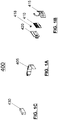
FIGS. 1A, 1B and 1C are prospective views of a processing unit A, a user interface unit B and a power supply unit C, which units compose an electronic subassembly of the assembly ofFig. 1 ; -
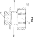
FIG. 2 is a vertical cross-section of the socket subassembly, along its longitudinal axis of symmetry (see also line Y-Y ofFIG. 3 ); -
FIG. 3 is a elevation view of the socket subassembly with strain gages of the strain transducer subassembly mounted in externally open. annular channel and indicating vertical cross-section line Y-Y, horizontal cross-section line X-X and a zone Z; -
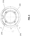
FIG. 4 is a horizontal cross-section along line X-X ofFIG, 3 showing the circumferential disposal of four strain gages of the strain transducer subassembly; -
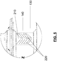
FIG. 5 depicts an enlarged view of zone Z shown inFIG. 3 ; -
FIG. 6 is a prospective, exploded view of the circular cover subassembly; and -
FIG. 7 is a diagrammatic view of the electronic subassembly. - Broadly describing, with reference to
FIGS.1 to 4 , an assembly, intercalated between a torque tool and a fastening element, for measuring torques and tightening angles, generally referenced as 10, comprises in combination; - a
socket subassembly 100 having an unitary elongated body, including at one extremity a firstengaging cavity 110, at an opposite extremity, a secondengaging cavity 120; and incorporating an externally open,annular channel 130 provided between the extremities of socket subassembly 100; - a
strain transducer subassembly 200, for measuring an torsional strain on thesocket subassembly 100, mounted in externally open,annular channel 130; - a
circular cover 300 attached tosocket subassembly 100 for enclosing externally open,annular channel 130; and - a
electronics subassembly 400 for converting the torsional strains on thesocket subassembly 100 to standard torque values and for determining tightening angular displacement;electronic subassembly 400 is interconnected to straintransducer subassembly 200 and mounted oncircular cover 300 to facestrain transducer subassembly 200; - Describing now in detail,
-
socket subassembly 100 includes first engagingcavity 110, shaped to conform to and engage with a torque tool exit shaft (not shown), usually of a square drive type; second engagingcavity 120 is shaped to conform to and engage with a fastening element, such as a bolt or nut of a specific size (also not shown); externally open,annular channel 130 is provided with acircular bottom surface 140, precision machined for mountingstrain transducer subassembly 200; -
strain transducer subassembly 200 comprises fourstrain gages 210, equally spaced from each other on circularbottom surface 140, intended for measuring torsional strains; each of the fourstrain gages 210, is of the 45 degree dual grid shear pattern and is made of constantan which is a copper/nickel alloy characterized by constant resistance under variations of temperature, reliability, and extensive service life; each of the fourstrain gages 210 comprises a pair ofparallel strain elements 220, so arranged that a convergence line ofparallel strain elements 220 is parallel to the longitudinal axis of symmetry ofsocket subassembly 100, for measuring torsional strains, only;strain transducer subassembly 200 is wired in a Wheatstone bridge to produce analog voltage signals, proportional to only torsional strains insocket assembly 100, and therefrom in the fastening element; -
circular cover subassembly 300 comprises a first and secondsemicircular segments
firstsemi-circular segment 305 incorporates anaxial protrusion 315 provided with aindented zone 320 including anopening 325, awindow 330 located above axial andradial protrusion 315, a first and a secondtransversal openings window 330; axial andradial protrusion 315 includes a pair offastening openings 350 for attachment tosocket sub-assembly 100; firstsemi-circular segment 305 includes diametrically opposed threadedopenings 355;
secondsemi-circular segment 310 incorporates a pair offastening openings 360, corresponding to diametrically opposed threadedopenings 355; the former and the latter are used for attachment of first and secondsemi-circular segments -
electronic subassembly 400 comprises a processing unit A, a user interface unit B and a power supply unit C; - Processing unit A includes:
- a
microcontroller 405 for digital and analog signal processing, such as an 8-bit microcomputer of the type made by Silicon Industries, under the name of C8051, mounted on firstsemi-circular segment 305 and connected to straintransducer subassembly 200, for converting the torsional strain into standard engineering units of torque, for measuring angular displacement by means of a sensor (not shown), for providing date/time function to time stamp tightening cycles and measured parameters, and for parameter and configuration memory storage. - user interface unit B includes;
- a
display 410, such as EINK display, manufactured by Kent Displays, mounted on firstsemi-circular segment 305 and viewed throughwindow 330, interconnected tomicrocontroller 405 providing a feature for displaying the selected imposed parameters (applied torque and/or angular displacement), and for displaying the running and final measured parameters (applied torque and/or angular displacement); - a
connection port 420, mounted to firstsemi-circular segment 305 and accessed through firsttransversal opening 340, is interconnected to processing unit A for communication to an external device, such as a personal computer or tool's own controller for the purpose of verification of applied torque or angular displacement, or for the purpose of controlling the tool shut-off at the imposed parameter (applied torque and/or angular displacement; - a
keypad 415, in the form of multiple discrete push-buttons, of membrane type, as the one made by Padtech Industries, mounted inindented zone 320, is interconnected to processing unit A viaopening 325, for selecting the desired parameter for verification (applied torque and/or angular displacement), or for selecting the parameter (applied torque and/or angular displacement) at which to signal the tool's own controller to shut-off at the imposed parameter (applied torque and/or angular displacement; - a pass/
fail indicator 418, in the form of a multi color LED, located in secondtransversal opening 345, and is interconnected to processing unit A for indicating if the measured parameter (applied torque and/or angular displacement), is within the pre-established upper parameter limit and lower parameter limit as defined by the user. - power supply unit C includes;
- a power source in the form of a
battery 430, such as a compact, rechargeable single cell Lipo, for poweringelectronic subassembly 400 and ; - a battery charging and protection circuit (not shown) for charging
battery 430 which is connected to a DC power source (not shown) and protects thebattery 430 from over-voltage, under voltage, short circuit and over-temperature. - The user will mount
assembly 10, intercalated between a torque tool (not shown) and a fastening element (also not shown), for measuring torques and tightening angles, onto torque tool, such as a powered torque tool (not shown), by inserting the driving tool shaft of the latter into first engagingcavity 110, wherein may be retained by a locking pin. The user will then engage the fastener assembly 19 (not shown) withassembly 10, respectively its secondengaging cavity 120. - The user, by using
display 410 andkeypad 415, can select and modify the ultimate torque and angular displacement values, which are displayed in standard engineering units, by incrementing or decrementing the values via the keypad pushbuttons, or select from a pre-established list of values. By the same means the user may also change the desired standard engineering units for torque, for example NM, ft lbs, etc.Display 410 also indicates the operational readiness ofassembly 10. - Under normal operation,
microcontroller 405, by means ofdisplay 410, will indicate "Ready" when the device has sufficient battery power, and is ready for measurements. - The user will then proceed tightening the fastener by operating the torque tool. On cessation of tool operation,
microcontroller 405 will indicate the final measured parameter(s) (applied torque and/or angular displacement) viadisplay 410 and via pass/fail indicator 418, During the tightening process,microcontroller 405 monitors and stores the running measured parameter(s) (applied torque and/or angular displacement) for analysis by the user. - In another operational variant, the user selects an ultimate torque value, and a desired ultimate angular displacement value, therefore providing a means for after the ultimate torque value is achieved
microcontroller 405 will zero the position count, and at a pre-established threshold prior to the desired ultimate angular position, themicrocontroller 405 sends a signal, or plurality of signals viaconnection port 420 to the tool's own controller (not shown) to control the approach of, and the shutoff of, the tool to achieve the imposed parameter (applied torque and/or angular displacement) within the desired upper and lower parameter limits.
Claims (1)
- An assembly (10), intercalated between a torque tool and a fastening element, for measuring torques and angular displacements of fasteners comprising, in combination:- a socket subassembly (100) having an unitary elongated body, including at one extremity a first engaging cavity (110), at an opposite extremity, a second engaging cavity (120); and incorporating an externally open, annular channel (130) provided between said extremities of said socket subassembly;- a strain transducer subassembly (200), for measuring torsional strains on said socket subassembly (100), mounted in said externally open, annular channel (130);- a circular cover (300) attached to said socket subassembly (100) for enclosing said externally open, annular channel (130); and- an electronic subassembly (400) for converting said torsional strains on said socket subassembly (100) to standard torque values and for determining tightening angular displacements; said electronic subassembly being interconnected to said strain transducer subassembly (200) and mounted on said circular cover (300) to face said strain transducer subassembly (200);said socket subassembly (100) including said first engaging cavity (110), shaped to conform to and engage with said torque tool exit shaft, usually of square drive type; said second engaging cavity (120) being shaped to conform to and engage with said fastening element, of a specific size; said externally open, annular channel (130) being provided with a circular bottom surface (140) for mounting said strain transducer subassembly (200);
said strain transducer subassembly (200) comprises four strain gages (210), equally spaced from each other on said circular bottom surface (140), intended for measuring torsional strains; each of said four strain gages (210) being of the 45 degree dual grid shear pattern and being made of constantan comprising a pair of parallel, juxtaposed strain elements (220), so arranged that a convergence line of said parallel, juxtaposed strain elements (220) is parallel to the longitudinal axis of symmetry of said socket subassembly (100), for measuring torsional strains, only; said strain transducer subassembly (200) being wired in a Wheatstone bridge to produce analog voltage signals, proportional to only torsional strains in said socket assembly (100), and therefrom in said fastening element;
said circular cover subassembly (300) comprising a first and second semicircular segments (305, 310); said first semi-circular segment (305) incorporating an axial protrusion and diametrically opposed threaded openings (355); said second semi-circular segment (310) incorporates a pair of fastening openings (360), corresponding to said diametrically opposed threaded openings (355); said diametrically opposed threaded openings (355) and said pair of fastening openings (360) being used for attachment of said first and second semi-circular segments (305, 310) by fasteners;
said electronic subassembly (400) comprising a processing unit, a user interface unit and a power supply unit; said processing unit including a microcontroller (405) for digital and analog signal processing, mounted on said first semi-circular segment (305) and connected to said strain transducer subassembly (200) for converting the torsional strain into standard engineering units of torque, for measuring angular displacement by means of a sensor for providing date/time function to time stamp tightening cycles and measured parameters, and for parameter and configuration memory storage;
said user interface unit including
a display (410), mounted on said first semi-circular segment (305) and interconnected to said microcontroller (405), for showing the selected imposed parameters, and for showing the running and final measured parameters;
a connection port (420), mounted to said first semi-circular segment (305) and interconnected to said processing unit for communication to an external device or for the purpose of controlling said torque tool shut-off at the imposed parameter;
a keypad (415), interconnected to said processing unit for selecting the desired parameter for verification, or for selecting the parameter at which to signal said torque tool's own controller to shut- off at the imposed parameter;
a pass/fail indicator (418), interconnected to said processing unit, for showing if the measured parameter, is within the pre-established upper parameter limit and lower parameter limit as defined by the user; and
said power supply unit including a power source in the form of a battery (430) and a battery charging and protection circuit.
Applications Claiming Priority (1)
| Application Number | Priority Date | Filing Date | Title |
|---|---|---|---|
| PCT/CA2011/001001 WO2011156918A2 (en) | 2011-09-02 | 2011-09-02 | Assembly, intercalated between a torque tool and a fastening element, for measuring torques and tightening angles |
Publications (3)
| Publication Number | Publication Date |
|---|---|
| EP2800959A2 EP2800959A2 (en) | 2014-11-12 |
| EP2800959A4 EP2800959A4 (en) | 2015-10-21 |
| EP2800959B1 true EP2800959B1 (en) | 2019-05-22 |
Family
ID=45348599
Family Applications (1)
| Application Number | Title | Priority Date | Filing Date |
|---|---|---|---|
| EP11795003.0A Active EP2800959B1 (en) | 2011-09-02 | 2011-09-02 | Assembly, intercalated between a torque tool and a fastening element, for measuring torques and tightening angles |
Country Status (6)
| Country | Link |
|---|---|
| US (1) | US8590402B2 (en) |
| EP (1) | EP2800959B1 (en) |
| CA (1) | CA2811139C (en) |
| DK (1) | DK2800959T3 (en) |
| ES (1) | ES2742352T3 (en) |
| WO (1) | WO2011156918A2 (en) |
Cited By (1)
| Publication number | Priority date | Publication date | Assignee | Title |
|---|---|---|---|---|
| WO2026069217A1 (en) * | 2024-09-27 | 2026-04-02 | Dino Paoli S.R.L. | Socket, tightening tool and method for transferring a signal |
Families Citing this family (11)
| Publication number | Priority date | Publication date | Assignee | Title |
|---|---|---|---|---|
| US20130279298A1 (en) * | 2012-04-19 | 2013-10-24 | William Mark PRENTICE | Monitoring of underwater mooring lines |
| CN103234451B (en) * | 2013-03-28 | 2015-08-19 | 重庆理工大学 | A kind of time gating angular displacement sensor system and method realizing online self-calibration |
| US9395257B2 (en) * | 2013-05-10 | 2016-07-19 | Snap-On Incorporated | Electronic torque tool with integrated real-time clock |
| CN103335835B (en) * | 2013-07-08 | 2016-03-02 | 中国空间技术研究院 | The system of selection of a kind of performance test device of clip, test method, assembly parameter and quality inspection method |
| ES2643378T3 (en) * | 2014-03-17 | 2017-11-22 | Raccorderie Metalliche S.P.A. | Compression fitting |
| DE102016116181A1 (en) * | 2016-08-01 | 2018-02-01 | Nuton GmbH | Single or multi-axis force measuring device with short deformation zone |
| EP3484662B1 (en) * | 2016-09-13 | 2024-11-06 | Milwaukee Electric Tool Corporation | Powered ratcheting torque wrench |
| US11453105B2 (en) | 2016-09-13 | 2022-09-27 | Milwaukee Electric Tool Corporation | Powered ratcheting torque wrench |
| US10625405B2 (en) | 2016-09-13 | 2020-04-21 | Milwaukee Electric Tool Corporation | Powered ratcheting torque wrench |
| EP3412412A1 (en) * | 2017-06-09 | 2018-12-12 | Wezag GmbH Werkzeugfabrik | Manually operated hand tool |
| SE1930254A1 (en) * | 2019-07-24 | 2020-11-17 | Atlas Copco Ind Technique Ab | Power tool attachment part with a torque sensor measuring strain |
Family Cites Families (28)
| Publication number | Priority date | Publication date | Assignee | Title |
|---|---|---|---|---|
| US3753625A (en) * | 1971-07-28 | 1973-08-21 | R Fabrizio | Cutting tool holder or adaptor |
| US3889490A (en) * | 1974-05-16 | 1975-06-17 | Felix J Nadolny | Torque control adaptor for ratchet wrench |
| DE3214889A1 (en) * | 1982-04-22 | 1983-10-27 | Robert Bosch Gmbh, 7000 Stuttgart | MEASURING VALVE FOR TORQUE AND / OR TURNING ANGLE MEASUREMENT, ESPECIALLY ON MOTOR DRIVEN SCREWDRIVERS |
| FR2543041B1 (en) * | 1983-03-25 | 1985-08-09 | Baudet Jean Pierre | METHOD AND INSTALLATION FOR TIGHTENING A SCREW TYPE CONNECTION WITH CONTROL OF THE MECHANICAL TENSION APPLIED TO THE SCREW |
| DE3528364A1 (en) * | 1985-08-07 | 1987-02-19 | Helmut Erb Elektr Messtechnik | Reactive torque sensor and method for adjusting its measuring range |
| US4802540A (en) * | 1988-01-29 | 1989-02-07 | Consolidated Devices Inc. | Electronic weighing scales |
| JPH02116479A (en) * | 1988-10-21 | 1990-05-01 | Fujitsu Ltd | Screw fastening device |
| US5058439A (en) * | 1990-06-06 | 1991-10-22 | The Babcock & Wilcox Company | Ut socket assembly |
| US5347871A (en) * | 1992-02-03 | 1994-09-20 | Teledyne Industries, Inc. | Strain sensor |
| DE19525231B4 (en) * | 1995-07-11 | 2004-03-04 | Hottinger Baldwin Messtechnik Gmbh | torque sensor |
| US5898598A (en) | 1996-10-25 | 1999-04-27 | Cooper Technologies Company | System and apparatus for a torque transducer with data processing capabilities |
| US6196071B1 (en) | 1998-02-23 | 2001-03-06 | Robert D. Shomo | Torque indicator socket |
| DE19842231C1 (en) * | 1998-09-15 | 2000-07-06 | Test Gmbh | Measuring device for determining the total tightening torque, the head friction torque and the preload force of a tightened screw connection |
| US6965835B2 (en) * | 2001-09-28 | 2005-11-15 | Spx Corporation | Torque angle sensing system and method with angle indication |
| US6629055B2 (en) | 2001-09-28 | 2003-09-30 | Spx Corporation | Apparatus and method for sensing torque angle |
| DE10217416C1 (en) * | 2002-04-18 | 2003-07-31 | Ivo Geilenbruegge | Rotational torque measuring device has measuring head containing torque transmission coupling element and measuring element |
| US7082865B2 (en) * | 2003-05-01 | 2006-08-01 | Ryeson Corporation | Digital torque wrench |
| US7475619B2 (en) * | 2005-04-22 | 2009-01-13 | The Stanley Works | Over torque proof socket |
| WO2007062813A1 (en) * | 2005-12-01 | 2007-06-07 | Hottinger Baldwin Messtechnik Gmbh | Strain gauge |
| JP4724137B2 (en) * | 2007-03-12 | 2011-07-13 | 前田金属工業株式会社 | Tightening torque measuring unit and bolt / nut tightening machine |
| US8083596B1 (en) * | 2007-11-26 | 2011-12-27 | Holmed Corporation | Torque limiter |
| CN201405312Y (en) * | 2009-02-06 | 2010-02-17 | 苏州宝时得电动工具有限公司 | Power tool |
| TWM372771U (en) * | 2009-05-20 | 2010-01-21 | Legend Lifestyle Products Corp | Torque detection display device for tool |
| TWM378377U (en) * | 2009-11-10 | 2010-04-11 | Legend Lifestyle Products Corp | Twisting force testing device |
| CN201653623U (en) * | 2009-11-20 | 2010-11-24 | 关弘科技股份有限公司 | torsion testing device |
| TWM378815U (en) * | 2009-11-20 | 2010-04-21 | Jia-Ming Li | Adapter tool capable of sensing torque |
| TWM392713U (en) * | 2010-07-12 | 2010-11-21 | Legend Lifestyle Products Corp | Wireless torque wrench with angle correction feature |
| US20120119919A1 (en) * | 2010-11-15 | 2012-05-17 | Legend Lifestyle Products Corp. | Multifunctional torque detection device |
-
2011
- 2011-09-02 ES ES11795003T patent/ES2742352T3/en active Active
- 2011-09-02 DK DK11795003.0T patent/DK2800959T3/en active
- 2011-09-02 US US13/261,598 patent/US8590402B2/en active Active
- 2011-09-02 WO PCT/CA2011/001001 patent/WO2011156918A2/en not_active Ceased
- 2011-09-02 CA CA2811139A patent/CA2811139C/en active Active
- 2011-09-02 EP EP11795003.0A patent/EP2800959B1/en active Active
Non-Patent Citations (1)
| Title |
|---|
| None * |
Cited By (1)
| Publication number | Priority date | Publication date | Assignee | Title |
|---|---|---|---|---|
| WO2026069217A1 (en) * | 2024-09-27 | 2026-04-02 | Dino Paoli S.R.L. | Socket, tightening tool and method for transferring a signal |
Also Published As
| Publication number | Publication date |
|---|---|
| ES2742352T3 (en) | 2020-02-14 |
| EP2800959A4 (en) | 2015-10-21 |
| DK2800959T3 (en) | 2019-08-19 |
| CA2811139A1 (en) | 2011-12-22 |
| US8590402B2 (en) | 2013-11-26 |
| CA2811139C (en) | 2018-03-20 |
| WO2011156918A2 (en) | 2011-12-22 |
| EP2800959A2 (en) | 2014-11-12 |
| WO2011156918A3 (en) | 2012-07-05 |
| US20130199307A1 (en) | 2013-08-08 |
Similar Documents
| Publication | Publication Date | Title |
|---|---|---|
| US8590402B2 (en) | Assembly, intercalated between a torque tool and a fastening element, for measuring torques and tightening angles | |
| US6810747B2 (en) | Test device for determining the friction and prestress values of screwed connections | |
| US8485075B1 (en) | Electronic torque wrench | |
| EP2248632B1 (en) | Wireless data transmitting and receiving system | |
| EP1614506B1 (en) | Tightening torque measuring unit and torque indicating tightening device | |
| US20030196497A1 (en) | Torque measuring device | |
| EP3484662B1 (en) | Powered ratcheting torque wrench | |
| US11396899B2 (en) | Bolt clamping force sensing washer | |
| JP3190778U (en) | Fastener capable of measuring tensile force | |
| JP6027670B1 (en) | Method for determining the fastening axial force of a tapping screw and its display device | |
| HK1199721A1 (en) | Method of compensating for adapters or extensions on an electronic torque wrench | |
| EP4076847B1 (en) | Clamping tool with tightening torque control | |
| US20220176526A1 (en) | Torque screwdriver arrangement and method for operating such a torque screwdriver arrangement | |
| TWI754533B (en) | Bolt clamping force sensor for bolt locking work | |
| CN210361096U (en) | Power tool | |
| US11529719B2 (en) | Bolt clamping force transducer for bolt tightening operation | |
| CN214793575U (en) | Bolt clamping force sensor for bolt locking operation | |
| CN114838861B (en) | Bolt tightening force sensor for bolt locking operations | |
| JPH0442027A (en) | Apparatus for measuring screw tightening force | |
| KR100912833B1 (en) | Residual torque inspection method using torque wrench | |
| EP3946816B1 (en) | Torque application tool | |
| US7096747B1 (en) | Hand tool with twisting force measuring functions | |
| RU2284260C1 (en) | Dynamometric wrench | |
| HK40049903A (en) | Method and system of using usb user interface in electronic torque wrench | |
| KR20000001191A (en) | Bolt connection tool for measurement |
Legal Events
| Date | Code | Title | Description |
|---|---|---|---|
| PUAI | Public reference made under article 153(3) epc to a published international application that has entered the european phase |
Free format text: ORIGINAL CODE: 0009012 |
|
| 17P | Request for examination filed |
Effective date: 20140331 |
|
| AK | Designated contracting states |
Kind code of ref document: A2 Designated state(s): AL AT BE BG CH CY CZ DE DK EE ES FI FR GB GR HR HU IE IS IT LI LT LU LV MC MK MT NL NO PL PT RO RS SE SI SK SM TR |
|
| DAX | Request for extension of the european patent (deleted) | ||
| A4 | Supplementary search report drawn up and despatched |
Effective date: 20150921 |
|
| RIC1 | Information provided on ipc code assigned before grant |
Ipc: B25B 23/142 20060101ALI20150915BHEP Ipc: G01B 7/30 20060101ALI20150915BHEP Ipc: G01L 5/24 20060101AFI20150915BHEP |
|
| RIC1 | Information provided on ipc code assigned before grant |
Ipc: B25B 23/142 20060101ALI20181018BHEP Ipc: B25B 13/06 20060101ALI20181018BHEP Ipc: G01L 5/24 20060101AFI20181018BHEP |
|
| GRAP | Despatch of communication of intention to grant a patent |
Free format text: ORIGINAL CODE: EPIDOSNIGR1 |
|
| STAA | Information on the status of an ep patent application or granted ep patent |
Free format text: STATUS: GRANT OF PATENT IS INTENDED |
|
| INTG | Intention to grant announced |
Effective date: 20181129 |
|
| GRAS | Grant fee paid |
Free format text: ORIGINAL CODE: EPIDOSNIGR3 |
|
| GRAA | (expected) grant |
Free format text: ORIGINAL CODE: 0009210 |
|
| STAA | Information on the status of an ep patent application or granted ep patent |
Free format text: STATUS: THE PATENT HAS BEEN GRANTED |
|
| AK | Designated contracting states |
Kind code of ref document: B1 Designated state(s): AL AT BE BG CH CY CZ DE DK EE ES FI FR GB GR HR HU IE IS IT LI LT LU LV MC MK MT NL NO PL PT RO RS SE SI SK SM TR |
|
| REG | Reference to a national code |
Ref country code: GB Ref legal event code: FG4D |
|
| REG | Reference to a national code |
Ref country code: CH Ref legal event code: EP |
|
| REG | Reference to a national code |
Ref country code: IE Ref legal event code: FG4D |
|
| REG | Reference to a national code |
Ref country code: DE Ref legal event code: R096 Ref document number: 602011059225 Country of ref document: DE |
|
| REG | Reference to a national code |
Ref country code: AT Ref legal event code: REF Ref document number: 1136684 Country of ref document: AT Kind code of ref document: T Effective date: 20190615 |
|
| REG | Reference to a national code |
Ref country code: DK Ref legal event code: T3 Effective date: 20190816 |
|
| REG | Reference to a national code |
Ref country code: NL Ref legal event code: FP |
|
| REG | Reference to a national code |
Ref country code: SE Ref legal event code: TRGR |
|
| REG | Reference to a national code |
Ref country code: LT Ref legal event code: MG4D |
|
| PG25 | Lapsed in a contracting state [announced via postgrant information from national office to epo] |
Ref country code: LT Free format text: LAPSE BECAUSE OF FAILURE TO SUBMIT A TRANSLATION OF THE DESCRIPTION OR TO PAY THE FEE WITHIN THE PRESCRIBED TIME-LIMIT Effective date: 20190522 Ref country code: AL Free format text: LAPSE BECAUSE OF FAILURE TO SUBMIT A TRANSLATION OF THE DESCRIPTION OR TO PAY THE FEE WITHIN THE PRESCRIBED TIME-LIMIT Effective date: 20190522 Ref country code: PT Free format text: LAPSE BECAUSE OF FAILURE TO SUBMIT A TRANSLATION OF THE DESCRIPTION OR TO PAY THE FEE WITHIN THE PRESCRIBED TIME-LIMIT Effective date: 20190922 Ref country code: NO Free format text: LAPSE BECAUSE OF FAILURE TO SUBMIT A TRANSLATION OF THE DESCRIPTION OR TO PAY THE FEE WITHIN THE PRESCRIBED TIME-LIMIT Effective date: 20190822 Ref country code: HR Free format text: LAPSE BECAUSE OF FAILURE TO SUBMIT A TRANSLATION OF THE DESCRIPTION OR TO PAY THE FEE WITHIN THE PRESCRIBED TIME-LIMIT Effective date: 20190522 Ref country code: FI Free format text: LAPSE BECAUSE OF FAILURE TO SUBMIT A TRANSLATION OF THE DESCRIPTION OR TO PAY THE FEE WITHIN THE PRESCRIBED TIME-LIMIT Effective date: 20190522 |
|
| PG25 | Lapsed in a contracting state [announced via postgrant information from national office to epo] |
Ref country code: GR Free format text: LAPSE BECAUSE OF FAILURE TO SUBMIT A TRANSLATION OF THE DESCRIPTION OR TO PAY THE FEE WITHIN THE PRESCRIBED TIME-LIMIT Effective date: 20190823 Ref country code: BG Free format text: LAPSE BECAUSE OF FAILURE TO SUBMIT A TRANSLATION OF THE DESCRIPTION OR TO PAY THE FEE WITHIN THE PRESCRIBED TIME-LIMIT Effective date: 20190822 Ref country code: RS Free format text: LAPSE BECAUSE OF FAILURE TO SUBMIT A TRANSLATION OF THE DESCRIPTION OR TO PAY THE FEE WITHIN THE PRESCRIBED TIME-LIMIT Effective date: 20190522 Ref country code: LV Free format text: LAPSE BECAUSE OF FAILURE TO SUBMIT A TRANSLATION OF THE DESCRIPTION OR TO PAY THE FEE WITHIN THE PRESCRIBED TIME-LIMIT Effective date: 20190522 |
|
| REG | Reference to a national code |
Ref country code: AT Ref legal event code: MK05 Ref document number: 1136684 Country of ref document: AT Kind code of ref document: T Effective date: 20190522 |
|
| PG25 | Lapsed in a contracting state [announced via postgrant information from national office to epo] |
Ref country code: EE Free format text: LAPSE BECAUSE OF FAILURE TO SUBMIT A TRANSLATION OF THE DESCRIPTION OR TO PAY THE FEE WITHIN THE PRESCRIBED TIME-LIMIT Effective date: 20190522 Ref country code: AT Free format text: LAPSE BECAUSE OF FAILURE TO SUBMIT A TRANSLATION OF THE DESCRIPTION OR TO PAY THE FEE WITHIN THE PRESCRIBED TIME-LIMIT Effective date: 20190522 Ref country code: SK Free format text: LAPSE BECAUSE OF FAILURE TO SUBMIT A TRANSLATION OF THE DESCRIPTION OR TO PAY THE FEE WITHIN THE PRESCRIBED TIME-LIMIT Effective date: 20190522 Ref country code: CZ Free format text: LAPSE BECAUSE OF FAILURE TO SUBMIT A TRANSLATION OF THE DESCRIPTION OR TO PAY THE FEE WITHIN THE PRESCRIBED TIME-LIMIT Effective date: 20190522 Ref country code: RO Free format text: LAPSE BECAUSE OF FAILURE TO SUBMIT A TRANSLATION OF THE DESCRIPTION OR TO PAY THE FEE WITHIN THE PRESCRIBED TIME-LIMIT Effective date: 20190522 |
|
| REG | Reference to a national code |
Ref country code: ES Ref legal event code: FG2A Ref document number: 2742352 Country of ref document: ES Kind code of ref document: T3 Effective date: 20200214 |
|
| REG | Reference to a national code |
Ref country code: DE Ref legal event code: R097 Ref document number: 602011059225 Country of ref document: DE |
|
| PG25 | Lapsed in a contracting state [announced via postgrant information from national office to epo] |
Ref country code: SM Free format text: LAPSE BECAUSE OF FAILURE TO SUBMIT A TRANSLATION OF THE DESCRIPTION OR TO PAY THE FEE WITHIN THE PRESCRIBED TIME-LIMIT Effective date: 20190522 |
|
| PLBE | No opposition filed within time limit |
Free format text: ORIGINAL CODE: 0009261 |
|
| STAA | Information on the status of an ep patent application or granted ep patent |
Free format text: STATUS: NO OPPOSITION FILED WITHIN TIME LIMIT |
|
| 26N | No opposition filed |
Effective date: 20200225 |
|
| PG25 | Lapsed in a contracting state [announced via postgrant information from national office to epo] |
Ref country code: PL Free format text: LAPSE BECAUSE OF FAILURE TO SUBMIT A TRANSLATION OF THE DESCRIPTION OR TO PAY THE FEE WITHIN THE PRESCRIBED TIME-LIMIT Effective date: 20190522 |
|
| PG25 | Lapsed in a contracting state [announced via postgrant information from national office to epo] |
Ref country code: SI Free format text: LAPSE BECAUSE OF FAILURE TO SUBMIT A TRANSLATION OF THE DESCRIPTION OR TO PAY THE FEE WITHIN THE PRESCRIBED TIME-LIMIT Effective date: 20190522 Ref country code: MC Free format text: LAPSE BECAUSE OF FAILURE TO SUBMIT A TRANSLATION OF THE DESCRIPTION OR TO PAY THE FEE WITHIN THE PRESCRIBED TIME-LIMIT Effective date: 20190522 |
|
| REG | Reference to a national code |
Ref country code: CH Ref legal event code: PL |
|
| PG25 | Lapsed in a contracting state [announced via postgrant information from national office to epo] |
Ref country code: CH Free format text: LAPSE BECAUSE OF NON-PAYMENT OF DUE FEES Effective date: 20190930 Ref country code: LU Free format text: LAPSE BECAUSE OF NON-PAYMENT OF DUE FEES Effective date: 20190902 Ref country code: LI Free format text: LAPSE BECAUSE OF NON-PAYMENT OF DUE FEES Effective date: 20190930 Ref country code: IE Free format text: LAPSE BECAUSE OF NON-PAYMENT OF DUE FEES Effective date: 20190902 |
|
| PG25 | Lapsed in a contracting state [announced via postgrant information from national office to epo] |
Ref country code: CY Free format text: LAPSE BECAUSE OF FAILURE TO SUBMIT A TRANSLATION OF THE DESCRIPTION OR TO PAY THE FEE WITHIN THE PRESCRIBED TIME-LIMIT Effective date: 20190522 |
|
| PG25 | Lapsed in a contracting state [announced via postgrant information from national office to epo] |
Ref country code: IS Free format text: LAPSE BECAUSE OF FAILURE TO SUBMIT A TRANSLATION OF THE DESCRIPTION OR TO PAY THE FEE WITHIN THE PRESCRIBED TIME-LIMIT Effective date: 20190922 |
|
| PG25 | Lapsed in a contracting state [announced via postgrant information from national office to epo] |
Ref country code: HU Free format text: LAPSE BECAUSE OF FAILURE TO SUBMIT A TRANSLATION OF THE DESCRIPTION OR TO PAY THE FEE WITHIN THE PRESCRIBED TIME-LIMIT; INVALID AB INITIO Effective date: 20110902 Ref country code: MT Free format text: LAPSE BECAUSE OF FAILURE TO SUBMIT A TRANSLATION OF THE DESCRIPTION OR TO PAY THE FEE WITHIN THE PRESCRIBED TIME-LIMIT Effective date: 20190522 |
|
| PG25 | Lapsed in a contracting state [announced via postgrant information from national office to epo] |
Ref country code: MK Free format text: LAPSE BECAUSE OF FAILURE TO SUBMIT A TRANSLATION OF THE DESCRIPTION OR TO PAY THE FEE WITHIN THE PRESCRIBED TIME-LIMIT Effective date: 20190522 |
|
| REG | Reference to a national code |
Ref country code: DE Ref legal event code: R082 Ref document number: 602011059225 Country of ref document: DE Representative=s name: LECOMTE, DIDIER, LU |
|
| PGFP | Annual fee paid to national office [announced via postgrant information from national office to epo] |
Ref country code: DE Payment date: 20250829 Year of fee payment: 15 Ref country code: DK Payment date: 20250812 Year of fee payment: 15 |
|
| PGFP | Annual fee paid to national office [announced via postgrant information from national office to epo] |
Ref country code: TR Payment date: 20250901 Year of fee payment: 15 Ref country code: NL Payment date: 20250829 Year of fee payment: 15 Ref country code: IT Payment date: 20250813 Year of fee payment: 15 |
|
| PGFP | Annual fee paid to national office [announced via postgrant information from national office to epo] |
Ref country code: BE Payment date: 20250814 Year of fee payment: 15 Ref country code: GB Payment date: 20250812 Year of fee payment: 15 |
|
| PGFP | Annual fee paid to national office [announced via postgrant information from national office to epo] |
Ref country code: FR Payment date: 20250812 Year of fee payment: 15 |
|
| PGFP | Annual fee paid to national office [announced via postgrant information from national office to epo] |
Ref country code: SE Payment date: 20250829 Year of fee payment: 15 |
|
| PGFP | Annual fee paid to national office [announced via postgrant information from national office to epo] |
Ref country code: ES Payment date: 20251007 Year of fee payment: 15 |