EP2800639B1 - Method FOR THE PRODUCTION AND THE PACKAGING OF STEEL RODS AND PROFILES - Google Patents
Method FOR THE PRODUCTION AND THE PACKAGING OF STEEL RODS AND PROFILES Download PDFInfo
- Publication number
- EP2800639B1 EP2800639B1 EP13710053.3A EP13710053A EP2800639B1 EP 2800639 B1 EP2800639 B1 EP 2800639B1 EP 13710053 A EP13710053 A EP 13710053A EP 2800639 B1 EP2800639 B1 EP 2800639B1
- Authority
- EP
- European Patent Office
- Prior art keywords
- bar portions
- housings
- rotating cylinder
- grooves
- bars
- Prior art date
- Legal status (The legal status is an assumption and is not a legal conclusion. Google has not performed a legal analysis and makes no representation as to the accuracy of the status listed.)
- Active
Links
Images

Classifications
-
- B—PERFORMING OPERATIONS; TRANSPORTING
- B21—MECHANICAL METAL-WORKING WITHOUT ESSENTIALLY REMOVING MATERIAL; PUNCHING METAL
- B21B—ROLLING OF METAL
- B21B43/00—Cooling beds, whether stationary or moving; Means specially associated with cooling beds, e.g. for braking work or for transferring it to or from the bed
-
- B—PERFORMING OPERATIONS; TRANSPORTING
- B21—MECHANICAL METAL-WORKING WITHOUT ESSENTIALLY REMOVING MATERIAL; PUNCHING METAL
- B21B—ROLLING OF METAL
- B21B1/00—Metal-rolling methods or mills for making semi-finished products of solid or profiled cross-section; Sequence of operations in milling trains; Layout of rolling-mill plant, e.g. grouping of stands; Succession of passes or of sectional pass alternations
- B21B1/16—Metal-rolling methods or mills for making semi-finished products of solid or profiled cross-section; Sequence of operations in milling trains; Layout of rolling-mill plant, e.g. grouping of stands; Succession of passes or of sectional pass alternations for rolling wire rods, bars, merchant bars, rounds wire or material of like small cross-section
-
- B—PERFORMING OPERATIONS; TRANSPORTING
- B21—MECHANICAL METAL-WORKING WITHOUT ESSENTIALLY REMOVING MATERIAL; PUNCHING METAL
- B21B—ROLLING OF METAL
- B21B43/00—Cooling beds, whether stationary or moving; Means specially associated with cooling beds, e.g. for braking work or for transferring it to or from the bed
- B21B43/003—Transfer to bed
-
- B—PERFORMING OPERATIONS; TRANSPORTING
- B21—MECHANICAL METAL-WORKING WITHOUT ESSENTIALLY REMOVING MATERIAL; PUNCHING METAL
- B21B—ROLLING OF METAL
- B21B43/00—Cooling beds, whether stationary or moving; Means specially associated with cooling beds, e.g. for braking work or for transferring it to or from the bed
- B21B43/02—Cooling beds comprising rakes racks, walking beams or bars
-
- B—PERFORMING OPERATIONS; TRANSPORTING
- B21—MECHANICAL METAL-WORKING WITHOUT ESSENTIALLY REMOVING MATERIAL; PUNCHING METAL
- B21B—ROLLING OF METAL
- B21B43/00—Cooling beds, whether stationary or moving; Means specially associated with cooling beds, e.g. for braking work or for transferring it to or from the bed
- B21B43/12—Devices for positioning workpieces "flushed", i.e. with all their axial ends arranged in line on cooling beds or on co-operating conveyors, e.g. before cutting
Definitions
- the present invention generally relates to the production and the packaging of steel rods and profiles.
- the invention relates to a method for the continuous production and packaging of bars and/or steel profiles from liquid metal, comprising a steel block, composed of a melting furnace for scrap and secondary metallurgy, a block casting, act in particular billets, a block of extraction, a rolling block and a finishing block for the packaging of the bars in bundles of weight default and ready for sale, in which the aforesaid blocks are all in line.
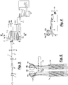
- FIG. 1 An example of a plant for the production and the packaging of steel bars of the traditional type and realized by the same Applicant is shown in the block diagram of figures 1 and 2 attached ( figure 2 is a sectional view taken along the line II-II of Figure 1 ), where 1 denotes a bar of indefinite length present at the beginning of the production line, number 2 indicates the rolling stage, with 3 is shown a cooling station, with 4 is shown a separation station of the scrap, with 5 is indicated a diverter device, while with 6 is shown a cutting shear for cut the bar 1 to a fixed length Lh (equal to the maximum length commercial) or lengths equal to one or more multiples of this length Lh, and with 7 is indicated a speed changing device (braking device), able to handle the bar portions 1a, 1b at a speed rate such that the bar portions 1a, 1b can be placed within respective grooves or housing 18 (of length L) provided on the outer surface, respectively, of each drum or rotating cylinder 8a, 8b.
- Lh equal to the
- each bar 1 of indefinite length at the entrance of the line system is divided by the shear 6 in bars 1a, 1b of fixed length Lh or having a length equal to one or more multiples of the fixed length Lh, while the diverter device 5 directs the bars 1a, 1b, alternately and respectively, in the rotating cylinder 8a and in the rotating cylinder 8b, and the speed changing device 7 enables to restrain the bars 1a, 1b, so that the same reach a speed able to allow them to be inserted (according to the direction of flow F) inside the respective housings 18, of fixed length L, on the lateral surface of each rotating cylinder 8a, 8b.
- each housing 18 of the rotating cylinders 8a, 8b is greater than or equal to the maximum commercial length or fixed length Lh of each bar 1a, 1b.
- the positions of the bars 1a, 1b inside the housing 18 are the same, both for the rotating cylinder 8a and for the rotating cylinder 8b, and, therefore, in this way, the cylinder 8a downloads a first bar 1a on a first seat 19 of a cooling plate or bed 13, which has means for transporting the bars 1a, such as moving knives or blades.
- the moving knives move the first bar on a next seat 20 of the cooling plate 13 and the rotating cylinder 8b downloads the bar 1b on the first seat 19 of the cooling plate 13 before that the moving knives further transfer the bar 1b on the next seat 20.
- the layer 15 is moved toward the cutting shear 16, which shall, if necessary, cut the bars 1a, 1b of fixed length Lh to a further fixed length, thus forming a layer of bars 17 of fixed length, which is moved into the wrapping stations 10, into the binding stations 11 and into the packaging stations 12.
- object of the present invention is to provide a method for the production and packaging of bars and steel profiles, which, compared to the prior art, it would be extremely flexible, resulting in a reduction of time and costs for implementation, and avoids any overlap of the bars on the plate or cooling bed.
- the system object of the present invention is particularly compact and versatile, since it allows continuous production, treatment and packaging of bars and/or profiles of various lengths, always maintaining an efficient production speed, without the need to provide long waiting times in storage warehouses.
- a series of rotating cylinders have respective seats formed on the lateral surface of the cylinder, adapted to house bars and/or profiles of commercial length, one after the other and at different speeds, in such a way that the arrest of the above bars in a direction perpendicular to the direction of rotation of the cylinders takes place at different times in relation to the respective cylinder, without however causing any overlapping of the bars when they are discharged onto the cooling plate.
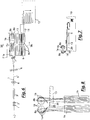
- FIG. 3-5 where the same elements of Figures 1 and 2 are indicated using the same reference numbers, with 1 is shown a bar or profile of indefinite length, which is placed at the beginning of the line, with 2 is indicated one rolling station, with 3 is shown a cooling station, with 4 is shown a scrap separation station, with 5 is indicated a diverter device, while with 6 is shown a cutting shear for cutting bars 1 to a fixed length Lh (equal to the maximum commercial length) or lengths equal to one or more multiples of the fixed length Lh, and with 7 is indicated a speed changing device (braking device), able to move the fixed length bar portions 1a, 1b at a speed rate able to brake and arrange the bars themselves 1a, 1b within each housing 18 (of length L, with L greater than the fixed length Lh), provided on the outer surface, respectively, of each rotating drum or cylinder 8a, 8b.
- the housings 18 are constituted by as many grooves provided in the lateral surface of the rotating cylinders 8a, 8b, arranged horizontal
- the grooves of the rotating cylinders 8a, 8b placed higher receive the respective bar portions 1a, 1b from the rolling station 2, while the lower grooves unload the bar portions 1a, 1b, which had been previously received in the high position, on the cooling plate 13. Furthermore, the speed changing device 7, installed in front of each rotating cylinder 8a, 8b, keeps the bar portions 1a, 1b at a suitable speed to stop and comfortably house said bar portions 1a, 1b into housings 18 of the rotating cylinders or drums 8a, 8b, while the diverter device 5 directs the bar portions 1a, 1b towards the grooves of the rotating cylinders 8a, 8b.
- each bar 1 of indefinite length at the entrance of the line system is divided, by the cutting shear 6, in bar portions 1a, 1b of fixed length Lh, which are housed inside the housings 18 of length L (with L > Lh and L greater than the length of the commercial bars), while the diverter device 5 directs the bars 1a, 1b, alternately and respectively, in the rotating cylinder 8a and in the rotating cylinder 8b, and the speed changing device 7 enables to restrain the bars 1a, 1b so that the same reach a speed able to allow them to be inserted (in the direction of flow F) inside the respective housings 18 on the lateral surface of each rotating cylinder 8a, 8b.
- the positions of the bar portions 1a, 1b inside the seats 18 are the same, both for the rotating cylinder 8a that for the rotating cylinder 8b.
- the bars 1a, 1b are arranged in the housings 18 of each rotating cylinder, respectively, 8a, 8b, always in the same positions, in such a way that, during handling the discharge of said bars 1a, 1b on the plate or cooling bed 13, the same do not overlap each other.
- both the cylinder 8a and the cylinder 8b downloading each a first bar portion 1a, 1b on a first receptacle 19 of the cooling plate 13, which has means for transporting the bar portions 1a, 1b, such as moving knives or blades.
- the moving knives move the bar portions 1a, 1b onto a second seat 20 of the cooling plate 13 only after both the bars 1a, 1b are discharged from the respective cylinders 8a, 8b.
- the cutting shears 6 subdivide rods 1 of indefinite length in bar portions 1a, 1b of fixed length Lh (the length Lh is such that it is possible to accommodate 2 or more bar portions 1a, 1b within the length L, with L equal to the length of the housing 18 of each rotating cylinder 8a, 8b, and, in particular, Lh ⁇ 1 ⁇ 2 L) and the diverter device 5 directs the bar portions 1a, 1b, alternately and respectively, towards the cylinder 8a and towards the cylinder 8b.
- the speed changing device 7 installed in front of a relative rotating cylinder 8a, 8b maintains the respective bars first at a speed such that the above-mentioned first bars can be arranged in the housings 18 of the rotating cylinder 8a, while the speed changing device 7 installed in front of the rotating cylinder 8b maintains the respective bar portions 1b at a speed such that said bar portions 1b can be arranged in the housings 18 of the rotating cylinder 8b which are close to or close, but different, compared to the corresponding housings 18 of the rotating cylinder 8a, so as not to overlap the bar portions 1a, 1b onto the cooling plate 13.
- the positions of the bar portions 1a, 1b are always the same both inside the rotating cylinder 8a and inside the cylinder 8b (as shown in detail in the attached Figure 8 ), and the rotating cylinders 8a and 8b download the bar portions 1a, 1b firstly on a first seat 19 of the cooling plate 13.
- the positions of the bars 1a, 1b inside the respective cylinders 8a, 8b are such that, when said bars 1a, 1b are discharged onto the cooling plate 13, the same do not overlap each other and, specifically, it is expected that the first bars are always placed in a housing 18 of the rotating cylinders 8a, 8b, in successive positions, one row to another and not interfering with each other within said housing 18 (as shown in detail in the attached Figure 8 ).
Landscapes
- Engineering & Computer Science (AREA)
- Mechanical Engineering (AREA)
- Basic Packing Technique (AREA)
- Metal Rolling (AREA)
- Attitude Control For Articles On Conveyors (AREA)
Description
- The present invention generally relates to the production and the packaging of steel rods and profiles.
- More particularly, the invention relates to a method for the continuous production and packaging of bars and/or steel profiles from liquid metal, comprising a steel block, composed of a melting furnace for scrap and secondary metallurgy, a block casting, act in particular billets, a block of extraction, a rolling block and a finishing block for the packaging of the bars in bundles of weight default and ready for sale, in which the aforesaid blocks are all in line.
- Production facilities of bars and/or steel profiles from liquid metal with machinery in line and/or break points of the production line are already known, according to which the bars, which may have different cross sections, are produced by lamination and then cut and packed.
- An example of a plant for the production and the packaging of steel bars of the traditional type and realized by the same Applicant is shown in the block diagram of
figures 1 and 2 attached (figure 2 is a sectional view taken along the line II-II ofFigure 1 ), where 1 denotes a bar of indefinite length present at the beginning of the production line,number 2 indicates the rolling stage, with 3 is shown a cooling station, with 4 is shown a separation station of the scrap, with 5 is indicated a diverter device, while with 6 is shown a cutting shear for cut thebar 1 to a fixed length Lh (equal to the maximum length commercial) or lengths equal to one or more multiples of this length Lh, and with 7 is indicated a speed changing device (braking device), able to handle thebar portions bar portions cylinder - Therefore, in detail, each
bar 1 of indefinite length at the entrance of the line system is divided by the shear 6 inbars bars cylinder 8a and in the rotatingcylinder 8b, and thespeed changing device 7 enables to restrain thebars respective housings 18, of fixed length L, on the lateral surface of each rotatingcylinder - In particular, the fixed length L of each
housing 18 of the rotatingcylinders bar - The positions of the
bars housing 18 are the same, both for the rotatingcylinder 8a and for the rotatingcylinder 8b, and, therefore, in this way, thecylinder 8a downloads afirst bar 1a on afirst seat 19 of a cooling plate orbed 13, which has means for transporting thebars 1a, such as moving knives or blades. - Subsequently, the moving knives move the first bar on a
next seat 20 of thecooling plate 13 and the rotatingcylinder 8b downloads thebar 1b on thefirst seat 19 of thecooling plate 13 before that the moving knives further transfer thebar 1b on thenext seat 20. - The process continues in this way until the
bars suitable alignment rollers 9, where they are kept in place in order to be downloaded into aconveyor 14, in such a way as to form a suitable layer 15 composed of a plurality ofbars - At this point, the layer 15 is moved toward the
cutting shear 16, which shall, if necessary, cut thebars bars 17 of fixed length, which is moved into thewrapping stations 10, into thebinding stations 11 and into thepackaging stations 12. - The equipment described, as well as the production facilities of a known type, which provide packaging plant of the bars placed downstream of the rolling train, have some drawbacks, including that of not allowing a high packaging speed of the bars, not dealing with different profiles and not being substantially compact, which also makes it the preamble of
claim 1 is based on documentWO 2005/123292 A1 .. - As part of the above requirements, therefore, object of the present invention is to provide a method for the production and packaging of bars and steel profiles, which, compared to the prior art, it would be extremely flexible, resulting in a reduction of time and costs for implementation, and avoids any overlap of the bars on the plate or cooling bed.
- These and other objects are achieved by providing a method for the production and packaging of bars and steel profiles, according to the appended
claim 1, Other detailed technical features are disclosed in the dependent claims. - Advantageously, the system object of the present invention is particularly compact and versatile, since it allows continuous production, treatment and packaging of bars and/or profiles of various lengths, always maintaining an efficient production speed, without the need to provide long waiting times in storage warehouses.
- In particular, a series of rotating cylinders have respective seats formed on the lateral surface of the cylinder, adapted to house bars and/or profiles of commercial length, one after the other and at different speeds, in such a way that the arrest of the above bars in a direction perpendicular to the direction of rotation of the cylinders takes place at different times in relation to the respective cylinder, without however causing any overlapping of the bars when they are discharged onto the cooling plate.
- By way of example and without limitative or exhaustive purposes, the areas of use of the fixing system of the invention are the following:
The objects and advantages mentioned above, as well as others which will emerge hereinafter, become more evident from the following description, relating to preferred embodiments of the invention, given as an example and preferred, but not limitative, and the attached drawings, in which: -
Figure 1 shows a block diagram of a plant for the production and packaging of bars and steel profiles, realized according to the prior art; -
Figure 2 is a schematic sectional view taken along the line II-II ofFigure 1 ; -
Figure 3 shows a block diagram of a first embodiment of a plant for a method for the production and packaging of bars and steel profiles according to the present invention; -
Figure 4 is a schematic sectional view taken along the line IV-IV ofFigure 3 ; -
Figure 5 is a schematic view of the deposition process of the bars on the plate or cooling bed implemented in the system ofFigure 3 , according to the present invention; -
Figure 6 shows a block diagram of a further embodiment of plant for a method for the production and packaging of bars and steel profiles according to the present invention; -
Figure 7 is a schematic sectional view taken along the line VII-VII ofFigure 6 ; -
Figure 8 is a schematic view of the deposition process of the bars on the plate or cooling bed implemented in the plant according tofigure 6 , according to the present invention. - With particular reference to
figures 3-5 mentioned, where the same elements ofFigures 1 and 2 are indicated using the same reference numbers, with 1 is shown a bar or profile of indefinite length, which is placed at the beginning of the line, with 2 is indicated one rolling station, with 3 is shown a cooling station, with 4 is shown a scrap separation station, with 5 is indicated a diverter device, while with 6 is shown a cutting shear forcutting bars 1 to a fixed length Lh (equal to the maximum commercial length) or lengths equal to one or more multiples of the fixed length Lh, and with 7 is indicated a speed changing device (braking device), able to move the fixedlength bar portions cylinder housings 18 are constituted by as many grooves provided in the lateral surface of the rotatingcylinders - The grooves of the rotating
cylinders respective bar portions rolling station 2, while the lower grooves unload thebar portions cooling plate 13. Furthermore, thespeed changing device 7, installed in front of each rotatingcylinder bar portions bar portions housings 18 of the rotating cylinders ordrums bar portions cylinders - Then, each
bar 1 of indefinite length at the entrance of the line system is divided, by the cutting shear 6, inbar portions housings 18 of length L (with L > Lh and L greater than the length of the commercial bars), while the diverter device 5 directs thebars cylinder 8a and in the rotatingcylinder 8b, and thespeed changing device 7 enables to restrain thebars respective housings 18 on the lateral surface of each rotatingcylinder - The positions of the
bar portions seats 18 are the same, both for the rotatingcylinder 8a that for the rotatingcylinder 8b. - In particular, it is expected that the
bars housings 18 of each rotating cylinder, respectively, 8a, 8b, always in the same positions, in such a way that, during handling the discharge of saidbars cooling bed 13, the same do not overlap each other. - In detail, both the
cylinder 8a and thecylinder 8b downloading each afirst bar portion first receptacle 19 of thecooling plate 13, which has means for transporting thebar portions - Subsequently, the moving knives move the
bar portions second seat 20 of thecooling plate 13 only after both thebars respective cylinders - The process continues in this way until the
bar portions suitable alignment rollers 9, where they are kept in place in order to be downloaded into thewrapping station 10 and into abinding station 11 and into apackaging station 12. - In order to make better use of the capacity (limited) for housing the
cooling plate 13, it is possible to use a system of production and packaging of bars and/or profiles such as that illustrated in the attachedFigures 6-8 , according to which the cutting shears 6subdivide rods 1 of indefinite length inbar portions more bar portions housing 18 of each rotatingcylinder bar portions cylinder 8a and towards thecylinder 8b. - Furthermore, the
speed changing device 7 installed in front of a relative rotatingcylinder housings 18 of the rotatingcylinder 8a, while thespeed changing device 7 installed in front of the rotatingcylinder 8b maintains therespective bar portions 1b at a speed such that saidbar portions 1b can be arranged in thehousings 18 of the rotatingcylinder 8b which are close to or close, but different, compared to thecorresponding housings 18 of the rotatingcylinder 8a, so as not to overlap thebar portions cooling plate 13. - Then, the positions of the
bar portions cylinder 8a and inside thecylinder 8b (as shown in detail in the attachedFigure 8 ), and the rotatingcylinders bar portions first seat 19 of thecooling plate 13. - In particular, the positions of the
bars respective cylinders bars cooling plate 13, the same do not overlap each other and, specifically, it is expected that the first bars are always placed in ahousing 18 of the rotatingcylinders Figure 8 ). - In this way, it is loaded, cyclically and alternately, firstly the
entire housing 18 of a first rotatingcylinder 8a and secondly anotherhousing 18 of a second rotatingcylinder 8b. - At this point and, therefore, only after that both the
bar portions 1a, coming from the rotatingcylinder 8a, and thebar portions 1b, coming from the rotatingcylinder 8b, are placed in theseat 19 of thecooling plate 13, the moving blades of thecooling plate 13 to ensure transfer thebar portions seat 20, next and adjacent to theseat 19, of thecooling plate 13. - When the
bar portions alignment rollers 9, the same are kept in place in order to allow packaging and, in particular, the bars are first positioned on the inlet of thealignment rollers 9, while thebar portions 1b are placed at the output side of thealignment rollers 9. - In the
wrapping station 10, placed in front of thebinding stations 11 andpackaging station 12, two bundles of bars are simultaneously formed.
Claims (8)
- Method for the production and packaging of steel bars or rods and profiles, including the following steps:rolling rods or profiles (1) of indefinite length,scrap separating the rods or profiles (1),diverting the rods or profiles (1),cutting said bars or profiles (1) in bar portions (1a, 1b) having at least a first fixed length (LH),changing the speed of the bar portions by means of a speed changing device (7)providing at least two cylinders or rotating drums (8a, 8b),each of the at least two cylinders or rotating drums (8a, 8b) having an outer surface provided with grooves or housings (18), which during the rotation pass from an upper position wherein the grooves or housings (18) receive the bar portions (1a, 1b), to a lower position, wherein the grooves or housings (18) download the bar portions (1a, 1b),the grooves or housings (18) having a second fixed length (L), greater than said first fixed length (LH) and greater than the commercial length of the bars,the speed changing device being able to handle said bar portions (1a, 1b) at a set speed rate such that said portions can be placed within respective grooves or housings (18),so that the grooves or housings (18) in the upper position receive relative bar portions (1a, 1b), while the grooves or housings (18) in the lower position download the bar portions (1a, 1b), which have been previously received in the upper position, on at least one cooling plate (13),wherein each rotating cylinder (8a, 8b) is associated with a different speed changing device (7), so that said grooves or housings (18) of different rotating cylinders (8a, 8b) receive said bar portions (1a, 1b) at different speeds, depending on the fact that said grooves or housings (18) belong to one first (8a) or to at least one second rotating cylinder (8b), and so that said bar portions (1a, 1b) have different stop positions in the relative housings (18), in a direction perpendicular to the direction of rotation of said cylinders (8a, 8b), characterized in that said bar portions (1a, 1b) have the same positions within said housings (18), both for said first rotating cylinder (8a) and for said second rotating cylinder (8b), so that said bar portions (1a, 1b) are arranged within said grooves or housings (18) of each respective rotating cylinder (8a; 8b) always in the same positions, so that, during the download of the bar portions (1a, 1b) on the at least one cooling plate (13), the bar portions (1a, 1b) do not overlap each other.
- Method according to claim 1, characterized in that said bar portions (1a, 1b) are directed, respectively and alternately, into a first (8a) and into a second rotating cylinder (8b).
- Method according to claim 1 or 2, characterized in that said bar portions (1a, 1b) are transported from a first seat (19) to a second seat (20), adjacent to said first seat (19), of the cooling plate (13).
- Method according to claim 3, characterized in that the step of transporting said bar portions (1a, 1b) from a first seat (19) to a second seat (20), adjacent to said first seat (19), of the cooling plate (13), occurs only after the discharge of at least one bar portion (1a, 1b) from each rotating cylinder (8a, 8b).
- Method according to one of the claims 1-4, characterized in that said bar portions (1a, 1b), which are downloaded from said rotating cylinders (8a, 8b) and which are moved on said cooling plate (13), reach suitable alignment rollers (9), where said bar portions (1a, 1b) are kept in place in order to be downloaded into a wrapping station (10) and into a binding station (11) and into a packaging station (12).
- Method according to claim 5, characterized in that some bar portions (1a) are positioned at the inlet side of said alignment rollers (9), while other bar portions (1b) are placed at the output side of said alignment rollers (9), so that at least two bundles of bars are simultaneously formed in the wrapping station (10).
- Method according to one of the claims 1-6, characterized in that said speed changing device (7) keeps the relative bar portions (1b) at a rate such that said relative bar portions (1b) are housed in the grooves or housings (18) of at least one first rotating cylinder (8a) that are near or close to, but different than, the grooves or housings (18) of at least one second rotating cylinder (8b), so as not to overlap said bar portions (1a, 1b) onto the cooling plate (13).
- Method according to one of the claims 1-7, characterized in that a first groove or housing (18) of a first rotating cylinder (8a) and, later, a second groove or housing (18) of a second rotating cylinder (8b) are loaded cyclically and alternately.
Priority Applications (2)
| Application Number | Priority Date | Filing Date | Title |
|---|---|---|---|
| EP19204765.2A EP3620240A1 (en) | 2012-01-03 | 2013-01-03 | Method for the production and the packaging of steel rods and profiles |
| PL13710053T PL2800639T3 (en) | 2012-01-03 | 2013-01-03 | Method FOR THE PRODUCTION AND THE PACKAGING OF STEEL RODS AND PROFILES |
Applications Claiming Priority (2)
| Application Number | Priority Date | Filing Date | Title |
|---|---|---|---|
| IT000001A ITVI20120001A1 (en) | 2012-01-03 | 2012-01-03 | PLANT FOR THE PRODUCTION AND PACKAGING OF BARS AND STEEL PROFILES |
| PCT/IT2013/000003 WO2013102944A1 (en) | 2012-01-03 | 2013-01-03 | Plant for the production and the packaging of steel rods and profiles |
Related Child Applications (2)
| Application Number | Title | Priority Date | Filing Date |
|---|---|---|---|
| EP19204765.2A Division EP3620240A1 (en) | 2012-01-03 | 2013-01-03 | Method for the production and the packaging of steel rods and profiles |
| EP19204765.2A Division-Into EP3620240A1 (en) | 2012-01-03 | 2013-01-03 | Method for the production and the packaging of steel rods and profiles |
Publications (2)
| Publication Number | Publication Date |
|---|---|
| EP2800639A1 EP2800639A1 (en) | 2014-11-12 |
| EP2800639B1 true EP2800639B1 (en) | 2020-01-01 |
Family
ID=45614992
Family Applications (2)
| Application Number | Title | Priority Date | Filing Date |
|---|---|---|---|
| EP19204765.2A Withdrawn EP3620240A1 (en) | 2012-01-03 | 2013-01-03 | Method for the production and the packaging of steel rods and profiles |
| EP13710053.3A Active EP2800639B1 (en) | 2012-01-03 | 2013-01-03 | Method FOR THE PRODUCTION AND THE PACKAGING OF STEEL RODS AND PROFILES |
Family Applications Before (1)
| Application Number | Title | Priority Date | Filing Date |
|---|---|---|---|
| EP19204765.2A Withdrawn EP3620240A1 (en) | 2012-01-03 | 2013-01-03 | Method for the production and the packaging of steel rods and profiles |
Country Status (7)
| Country | Link |
|---|---|
| US (2) | US20140352383A1 (en) |
| EP (2) | EP3620240A1 (en) |
| ES (1) | ES2778060T3 (en) |
| IT (1) | ITVI20120001A1 (en) |
| PL (1) | PL2800639T3 (en) |
| RU (1) | RU2703711C2 (en) |
| WO (1) | WO2013102944A1 (en) |
Families Citing this family (3)
| Publication number | Priority date | Publication date | Assignee | Title |
|---|---|---|---|---|
| ITVI20120001A1 (en) | 2012-01-03 | 2013-07-04 | Sms Meer Spa | PLANT FOR THE PRODUCTION AND PACKAGING OF BARS AND STEEL PROFILES |
| EP2821154B2 (en) * | 2013-07-05 | 2022-05-25 | Primetals Technologies Austria GmbH | Method for handling long rolled products coming from different strands of a rolling mill |
| IT202300009486A1 (en) * | 2023-05-11 | 2024-11-11 | Danieli Off Mecc | DEVICE AND METHOD FOR PRODUCING AND UNLOADING ROLLED BARS |
Citations (10)
| Publication number | Priority date | Publication date | Assignee | Title |
|---|---|---|---|---|
| US3497084A (en) | 1968-02-28 | 1970-02-24 | Morgan Construction Co | Means for counting,bundling and weighing of elongated elements |
| US3651921A (en) | 1970-06-17 | 1972-03-28 | Morgan Construction Co | Bar separator |
| US4006828A (en) | 1975-08-11 | 1977-02-08 | Morgan Construction Company | Apparatus for aligning the ends of product lengths |
| US4307594A (en) | 1979-11-28 | 1981-12-29 | Rolf Steinbock | Delivery system for hot-rolled workpieces |
| JPH02158512A (en) | 1988-12-12 | 1990-06-19 | Nkk Corp | How to align the tip of steel bar |
| US5191818A (en) | 1989-07-31 | 1993-03-09 | Pomini Farrel S.P.A. | Process and facility for shearing to length steel bars coming from a rolling mill |
| WO2005123292A1 (en) | 2004-06-16 | 2005-12-29 | Danieli & C. Officine Meccaniche S.P.A. | Bar packing plant and relative process |
| WO2006092404A1 (en) * | 2005-03-02 | 2006-09-08 | Danieli & C. Officine Meccaniche S.P.A. | Compact plant for continuous production of bars and/or profiles |
| WO2007003331A1 (en) | 2005-07-04 | 2007-01-11 | Sms Meer S.P.A. | System for the receiving and conveying of bars from a rolling mill towards a collection and discharge device |
| JP4951600B2 (en) | 2008-08-26 | 2012-06-13 | 住友重機械テクノフォート株式会社 | Aligning roller table |
Family Cites Families (5)
| Publication number | Priority date | Publication date | Assignee | Title |
|---|---|---|---|---|
| SU697219A1 (en) * | 1978-03-07 | 1979-11-15 | Челябинский Ордена Ленина Трубопрокатный Завод | Round rolled stock transfer apparatus |
| SU1615103A1 (en) * | 1988-08-01 | 1990-12-23 | Производственное объединение "Донпрессмаш" | Arrangement for piecewise dispense of flexible elongated rods |
| ITUD20010048A1 (en) * | 2001-03-08 | 2002-09-08 | Simac Spa | BAR RECEIVING AND UNLOADING DEVICE AND THE RESPECTIVE SYSTEM PARTICULARLY FOR HANDLING AND / OR PACKING DOWNSTREAM SYSTEMS D |
| US7219521B1 (en) * | 2006-09-19 | 2007-05-22 | Morgan Construction Company | Rolling mill product handling system |
| ITVI20120001A1 (en) | 2012-01-03 | 2013-07-04 | Sms Meer Spa | PLANT FOR THE PRODUCTION AND PACKAGING OF BARS AND STEEL PROFILES |
-
2012
- 2012-01-03 IT IT000001A patent/ITVI20120001A1/en unknown
-
2013
- 2013-01-03 WO PCT/IT2013/000003 patent/WO2013102944A1/en not_active Ceased
- 2013-01-03 PL PL13710053T patent/PL2800639T3/en unknown
- 2013-01-03 US US14/369,694 patent/US20140352383A1/en not_active Abandoned
- 2013-01-03 ES ES13710053T patent/ES2778060T3/en active Active
- 2013-01-03 EP EP19204765.2A patent/EP3620240A1/en not_active Withdrawn
- 2013-01-03 EP EP13710053.3A patent/EP2800639B1/en active Active
- 2013-01-03 RU RU2014116409A patent/RU2703711C2/en active IP Right Revival
-
2019
- 2019-05-24 US US16/422,570 patent/US11484923B2/en active Active
Patent Citations (10)
| Publication number | Priority date | Publication date | Assignee | Title |
|---|---|---|---|---|
| US3497084A (en) | 1968-02-28 | 1970-02-24 | Morgan Construction Co | Means for counting,bundling and weighing of elongated elements |
| US3651921A (en) | 1970-06-17 | 1972-03-28 | Morgan Construction Co | Bar separator |
| US4006828A (en) | 1975-08-11 | 1977-02-08 | Morgan Construction Company | Apparatus for aligning the ends of product lengths |
| US4307594A (en) | 1979-11-28 | 1981-12-29 | Rolf Steinbock | Delivery system for hot-rolled workpieces |
| JPH02158512A (en) | 1988-12-12 | 1990-06-19 | Nkk Corp | How to align the tip of steel bar |
| US5191818A (en) | 1989-07-31 | 1993-03-09 | Pomini Farrel S.P.A. | Process and facility for shearing to length steel bars coming from a rolling mill |
| WO2005123292A1 (en) | 2004-06-16 | 2005-12-29 | Danieli & C. Officine Meccaniche S.P.A. | Bar packing plant and relative process |
| WO2006092404A1 (en) * | 2005-03-02 | 2006-09-08 | Danieli & C. Officine Meccaniche S.P.A. | Compact plant for continuous production of bars and/or profiles |
| WO2007003331A1 (en) | 2005-07-04 | 2007-01-11 | Sms Meer S.P.A. | System for the receiving and conveying of bars from a rolling mill towards a collection and discharge device |
| JP4951600B2 (en) | 2008-08-26 | 2012-06-13 | 住友重機械テクノフォート株式会社 | Aligning roller table |
Also Published As
| Publication number | Publication date |
|---|---|
| US11484923B2 (en) | 2022-11-01 |
| RU2014116409A (en) | 2016-02-27 |
| EP3620240A1 (en) | 2020-03-11 |
| EP2800639A1 (en) | 2014-11-12 |
| ES2778060T3 (en) | 2020-08-07 |
| WO2013102944A1 (en) | 2013-07-11 |
| PL2800639T3 (en) | 2020-07-13 |
| US20140352383A1 (en) | 2014-12-04 |
| US20190275574A1 (en) | 2019-09-12 |
| ITVI20120001A1 (en) | 2013-07-04 |
| RU2703711C2 (en) | 2019-10-21 |
Similar Documents
| Publication | Publication Date | Title |
|---|---|---|
| US5182847A (en) | Method and apparatus for manufacturing hot-rolled strips or sections from continuously cast primary material | |
| US11484923B2 (en) | Plant for the production and the packaging of steel bars or rods | |
| CN109641249A (en) | It can be in the production equipment and method for running production equipment in fault condition that continuous operation is run | |
| CZ336095A3 (en) | Production line for casting slabs of medium thickness with a system of furnaces, storage facilities and slab arrangement | |
| EP1187686B1 (en) | Integrated plant for the production of rolled stock | |
| CN103624081A (en) | Intermediate mill area of casting-rolling composite equipment | |
| US20150360282A1 (en) | Modular micro mill and method of manufacturing a steel long product | |
| EP1877203B1 (en) | Compact plant for continuous production of bars and/or profiles | |
| US4487540A (en) | Stacking machine for rolled bar shapes | |
| CN110280698B (en) | Method for treating long rolled products from different strands of a rolling mill | |
| JP2018518369A (en) | Method for producing a metallic strip in a casting and rolling process | |
| EP0872306A2 (en) | A bar deburring plant | |
| EP2554281B1 (en) | Method and apparatus for a continuous rolling | |
| US7533552B2 (en) | System for the production of extruded aluminum profiles | |
| EP2410274A1 (en) | Temperature maintenance and/or heating apparatus for long metal products and relative method | |
| EP0642850A1 (en) | Rolling mill material handling system | |
| ITUD20100150A1 (en) | MAINTENANCE EQUIPMENT IN TEMPERATURE AND / OR POSSIBLE WARMING OF LONG METAL PRODUCTS AND ITS PROCEDURE | |
| JP2002503155A (en) | Manufacture of metal strip | |
| EP0630696B1 (en) | Method and device for careful cooling hot-rolled bars of special or stainless steel | |
| JPH0615854U (en) | Slab unloader for continuous casting equipment | |
| ITMI991437A1 (en) | METHOD AND PLANT FOR LAMINATING MULTIPLE BILLETS SUPPLIED BY A HEATING OVEN BILETS PLACED UPstream OF A LAMINATION TRAIN | |
| WO2013048795A1 (en) | Method of operating rolling mill conveyor | |
| MXPA00011617A (en) | Process for forming bundles with an exact and predetermined number of pieces of bars, by means of counting up and forming bar layers directly over a cooling bed. | |
| JP2020515411A (en) | Furnace for heating metal strip, and apparatus and method for producing metal strip by a casting and rolling method |
Legal Events
| Date | Code | Title | Description |
|---|---|---|---|
| PUAI | Public reference made under article 153(3) epc to a published international application that has entered the european phase |
Free format text: ORIGINAL CODE: 0009012 |
|
| 17P | Request for examination filed |
Effective date: 20140519 |
|
| AK | Designated contracting states |
Kind code of ref document: A1 Designated state(s): AL AT BE BG CH CY CZ DE DK EE ES FI FR GB GR HR HU IE IS IT LI LT LU LV MC MK MT NL NO PL PT RO RS SE SI SK SM TR |
|
| DAX | Request for extension of the european patent (deleted) | ||
| TPAC | Observations filed by third parties |
Free format text: ORIGINAL CODE: EPIDOSNTIPA |
|
| 17Q | First examination report despatched |
Effective date: 20160914 |
|
| STAA | Information on the status of an ep patent application or granted ep patent |
Free format text: STATUS: EXAMINATION IS IN PROGRESS |
|
| TPAC | Observations filed by third parties |
Free format text: ORIGINAL CODE: EPIDOSNTIPA |
|
| GRAP | Despatch of communication of intention to grant a patent |
Free format text: ORIGINAL CODE: EPIDOSNIGR1 |
|
| STAA | Information on the status of an ep patent application or granted ep patent |
Free format text: STATUS: GRANT OF PATENT IS INTENDED |
|
| INTG | Intention to grant announced |
Effective date: 20190621 |
|
| GRAS | Grant fee paid |
Free format text: ORIGINAL CODE: EPIDOSNIGR3 |
|
| GRAJ | Information related to disapproval of communication of intention to grant by the applicant or resumption of examination proceedings by the epo deleted |
Free format text: ORIGINAL CODE: EPIDOSDIGR1 |
|
| GRAL | Information related to payment of fee for publishing/printing deleted |
Free format text: ORIGINAL CODE: EPIDOSDIGR3 |
|
| STAA | Information on the status of an ep patent application or granted ep patent |
Free format text: STATUS: EXAMINATION IS IN PROGRESS |
|
| GRAR | Information related to intention to grant a patent recorded |
Free format text: ORIGINAL CODE: EPIDOSNIGR71 |
|
| STAA | Information on the status of an ep patent application or granted ep patent |
Free format text: STATUS: GRANT OF PATENT IS INTENDED |
|
| INTC | Intention to grant announced (deleted) | ||
| GRAA | (expected) grant |
Free format text: ORIGINAL CODE: 0009210 |
|
| STAA | Information on the status of an ep patent application or granted ep patent |
Free format text: STATUS: THE PATENT HAS BEEN GRANTED |
|
| INTG | Intention to grant announced |
Effective date: 20191120 |
|
| AK | Designated contracting states |
Kind code of ref document: B1 Designated state(s): AL AT BE BG CH CY CZ DE DK EE ES FI FR GB GR HR HU IE IS IT LI LT LU LV MC MK MT NL NO PL PT RO RS SE SI SK SM TR |
|
| REG | Reference to a national code |
Ref country code: GB Ref legal event code: FG4D |
|
| REG | Reference to a national code |
Ref country code: CH Ref legal event code: EP Ref country code: AT Ref legal event code: REF Ref document number: 1219129 Country of ref document: AT Kind code of ref document: T Effective date: 20200115 |
|
| REG | Reference to a national code |
Ref country code: DE Ref legal event code: R096 Ref document number: 602013064569 Country of ref document: DE |
|
| REG | Reference to a national code |
Ref country code: IE Ref legal event code: FG4D |
|
| REG | Reference to a national code |
Ref country code: NL Ref legal event code: MP Effective date: 20200101 |
|
| REG | Reference to a national code |
Ref country code: LT Ref legal event code: MG4D |
|
| PG25 | Lapsed in a contracting state [announced via postgrant information from national office to epo] |
Ref country code: CZ Free format text: LAPSE BECAUSE OF FAILURE TO SUBMIT A TRANSLATION OF THE DESCRIPTION OR TO PAY THE FEE WITHIN THE PRESCRIBED TIME-LIMIT Effective date: 20200101 Ref country code: NL Free format text: LAPSE BECAUSE OF FAILURE TO SUBMIT A TRANSLATION OF THE DESCRIPTION OR TO PAY THE FEE WITHIN THE PRESCRIBED TIME-LIMIT Effective date: 20200101 Ref country code: NO Free format text: LAPSE BECAUSE OF FAILURE TO SUBMIT A TRANSLATION OF THE DESCRIPTION OR TO PAY THE FEE WITHIN THE PRESCRIBED TIME-LIMIT Effective date: 20200401 Ref country code: FI Free format text: LAPSE BECAUSE OF FAILURE TO SUBMIT A TRANSLATION OF THE DESCRIPTION OR TO PAY THE FEE WITHIN THE PRESCRIBED TIME-LIMIT Effective date: 20200101 Ref country code: LT Free format text: LAPSE BECAUSE OF FAILURE TO SUBMIT A TRANSLATION OF THE DESCRIPTION OR TO PAY THE FEE WITHIN THE PRESCRIBED TIME-LIMIT Effective date: 20200101 Ref country code: PT Free format text: LAPSE BECAUSE OF FAILURE TO SUBMIT A TRANSLATION OF THE DESCRIPTION OR TO PAY THE FEE WITHIN THE PRESCRIBED TIME-LIMIT Effective date: 20200527 Ref country code: RS Free format text: LAPSE BECAUSE OF FAILURE TO SUBMIT A TRANSLATION OF THE DESCRIPTION OR TO PAY THE FEE WITHIN THE PRESCRIBED TIME-LIMIT Effective date: 20200101 |
|
| REG | Reference to a national code |
Ref country code: ES Ref legal event code: FG2A Ref document number: 2778060 Country of ref document: ES Kind code of ref document: T3 Effective date: 20200807 |
|
| PG25 | Lapsed in a contracting state [announced via postgrant information from national office to epo] |
Ref country code: BG Free format text: LAPSE BECAUSE OF FAILURE TO SUBMIT A TRANSLATION OF THE DESCRIPTION OR TO PAY THE FEE WITHIN THE PRESCRIBED TIME-LIMIT Effective date: 20200401 Ref country code: LV Free format text: LAPSE BECAUSE OF FAILURE TO SUBMIT A TRANSLATION OF THE DESCRIPTION OR TO PAY THE FEE WITHIN THE PRESCRIBED TIME-LIMIT Effective date: 20200101 Ref country code: SE Free format text: LAPSE BECAUSE OF FAILURE TO SUBMIT A TRANSLATION OF THE DESCRIPTION OR TO PAY THE FEE WITHIN THE PRESCRIBED TIME-LIMIT Effective date: 20200101 Ref country code: IS Free format text: LAPSE BECAUSE OF FAILURE TO SUBMIT A TRANSLATION OF THE DESCRIPTION OR TO PAY THE FEE WITHIN THE PRESCRIBED TIME-LIMIT Effective date: 20200501 Ref country code: GR Free format text: LAPSE BECAUSE OF FAILURE TO SUBMIT A TRANSLATION OF THE DESCRIPTION OR TO PAY THE FEE WITHIN THE PRESCRIBED TIME-LIMIT Effective date: 20200402 Ref country code: HR Free format text: LAPSE BECAUSE OF FAILURE TO SUBMIT A TRANSLATION OF THE DESCRIPTION OR TO PAY THE FEE WITHIN THE PRESCRIBED TIME-LIMIT Effective date: 20200101 |
|
| REG | Reference to a national code |
Ref country code: CH Ref legal event code: PL |
|
| REG | Reference to a national code |
Ref country code: DE Ref legal event code: R026 Ref document number: 602013064569 Country of ref document: DE |
|
| PLBI | Opposition filed |
Free format text: ORIGINAL CODE: 0009260 |
|
| REG | Reference to a national code |
Ref country code: BE Ref legal event code: MM Effective date: 20200131 |
|
| PG25 | Lapsed in a contracting state [announced via postgrant information from national office to epo] |
Ref country code: SM Free format text: LAPSE BECAUSE OF FAILURE TO SUBMIT A TRANSLATION OF THE DESCRIPTION OR TO PAY THE FEE WITHIN THE PRESCRIBED TIME-LIMIT Effective date: 20200101 Ref country code: EE Free format text: LAPSE BECAUSE OF FAILURE TO SUBMIT A TRANSLATION OF THE DESCRIPTION OR TO PAY THE FEE WITHIN THE PRESCRIBED TIME-LIMIT Effective date: 20200101 Ref country code: DK Free format text: LAPSE BECAUSE OF FAILURE TO SUBMIT A TRANSLATION OF THE DESCRIPTION OR TO PAY THE FEE WITHIN THE PRESCRIBED TIME-LIMIT Effective date: 20200101 Ref country code: RO Free format text: LAPSE BECAUSE OF FAILURE TO SUBMIT A TRANSLATION OF THE DESCRIPTION OR TO PAY THE FEE WITHIN THE PRESCRIBED TIME-LIMIT Effective date: 20200101 Ref country code: MC Free format text: LAPSE BECAUSE OF FAILURE TO SUBMIT A TRANSLATION OF THE DESCRIPTION OR TO PAY THE FEE WITHIN THE PRESCRIBED TIME-LIMIT Effective date: 20200101 Ref country code: LU Free format text: LAPSE BECAUSE OF NON-PAYMENT OF DUE FEES Effective date: 20200103 Ref country code: SK Free format text: LAPSE BECAUSE OF FAILURE TO SUBMIT A TRANSLATION OF THE DESCRIPTION OR TO PAY THE FEE WITHIN THE PRESCRIBED TIME-LIMIT Effective date: 20200101 |
|
| 26 | Opposition filed |
Opponent name: DANIELI & C. OFFICINE MECCANICHE S.P.A. Effective date: 20200929 |
|
| PLAB | Opposition data, opponent's data or that of the opponent's representative modified |
Free format text: ORIGINAL CODE: 0009299OPPO |
|
| PG25 | Lapsed in a contracting state [announced via postgrant information from national office to epo] |
Ref country code: LI Free format text: LAPSE BECAUSE OF NON-PAYMENT OF DUE FEES Effective date: 20200131 Ref country code: BE Free format text: LAPSE BECAUSE OF NON-PAYMENT OF DUE FEES Effective date: 20200131 Ref country code: CH Free format text: LAPSE BECAUSE OF NON-PAYMENT OF DUE FEES Effective date: 20200131 |
|
| PLAX | Notice of opposition and request to file observation + time limit sent |
Free format text: ORIGINAL CODE: EPIDOSNOBS2 |
|
| R26 | Opposition filed (corrected) |
Opponent name: DANIELI & C. OFFICINE MECCANICHE SPA Effective date: 20200929 |
|
| PG25 | Lapsed in a contracting state [announced via postgrant information from national office to epo] |
Ref country code: FR Free format text: LAPSE BECAUSE OF NON-PAYMENT OF DUE FEES Effective date: 20200301 Ref country code: IE Free format text: LAPSE BECAUSE OF NON-PAYMENT OF DUE FEES Effective date: 20200103 |
|
| PG25 | Lapsed in a contracting state [announced via postgrant information from national office to epo] |
Ref country code: SI Free format text: LAPSE BECAUSE OF FAILURE TO SUBMIT A TRANSLATION OF THE DESCRIPTION OR TO PAY THE FEE WITHIN THE PRESCRIBED TIME-LIMIT Effective date: 20200101 |
|
| GBPC | Gb: european patent ceased through non-payment of renewal fee |
Effective date: 20200401 |
|
| PLBB | Reply of patent proprietor to notice(s) of opposition received |
Free format text: ORIGINAL CODE: EPIDOSNOBS3 |
|
| PG25 | Lapsed in a contracting state [announced via postgrant information from national office to epo] |
Ref country code: GB Free format text: LAPSE BECAUSE OF NON-PAYMENT OF DUE FEES Effective date: 20200401 |
|
| REG | Reference to a national code |
Ref country code: AT Ref legal event code: UEP Ref document number: 1219129 Country of ref document: AT Kind code of ref document: T Effective date: 20200101 |
|
| PG25 | Lapsed in a contracting state [announced via postgrant information from national office to epo] |
Ref country code: MT Free format text: LAPSE BECAUSE OF FAILURE TO SUBMIT A TRANSLATION OF THE DESCRIPTION OR TO PAY THE FEE WITHIN THE PRESCRIBED TIME-LIMIT Effective date: 20200101 Ref country code: CY Free format text: LAPSE BECAUSE OF FAILURE TO SUBMIT A TRANSLATION OF THE DESCRIPTION OR TO PAY THE FEE WITHIN THE PRESCRIBED TIME-LIMIT Effective date: 20200101 |
|
| PLCK | Communication despatched that opposition was rejected |
Free format text: ORIGINAL CODE: EPIDOSNREJ1 |
|
| PG25 | Lapsed in a contracting state [announced via postgrant information from national office to epo] |
Ref country code: MK Free format text: LAPSE BECAUSE OF FAILURE TO SUBMIT A TRANSLATION OF THE DESCRIPTION OR TO PAY THE FEE WITHIN THE PRESCRIBED TIME-LIMIT Effective date: 20200101 Ref country code: AL Free format text: LAPSE BECAUSE OF FAILURE TO SUBMIT A TRANSLATION OF THE DESCRIPTION OR TO PAY THE FEE WITHIN THE PRESCRIBED TIME-LIMIT Effective date: 20200101 |
|
| APAH | Appeal reference modified |
Free format text: ORIGINAL CODE: EPIDOSCREFNO |
|
| APBM | Appeal reference recorded |
Free format text: ORIGINAL CODE: EPIDOSNREFNO |
|
| APBP | Date of receipt of notice of appeal recorded |
Free format text: ORIGINAL CODE: EPIDOSNNOA2O |
|
| APBQ | Date of receipt of statement of grounds of appeal recorded |
Free format text: ORIGINAL CODE: EPIDOSNNOA3O |
|
| P01 | Opt-out of the competence of the unified patent court (upc) registered |
Effective date: 20230515 |
|
| APAH | Appeal reference modified |
Free format text: ORIGINAL CODE: EPIDOSCREFNO |
|
| REG | Reference to a national code |
Ref country code: DE Ref legal event code: R100 Ref document number: 602013064569 Country of ref document: DE |
|
| APBU | Appeal procedure closed |
Free format text: ORIGINAL CODE: EPIDOSNNOA9O |
|
| PLBN | Opposition rejected |
Free format text: ORIGINAL CODE: 0009273 |
|
| STAA | Information on the status of an ep patent application or granted ep patent |
Free format text: STATUS: OPPOSITION REJECTED |
|
| 27O | Opposition rejected |
Effective date: 20241129 |
|
| PGFP | Annual fee paid to national office [announced via postgrant information from national office to epo] |
Ref country code: PL Payment date: 20251128 Year of fee payment: 14 |
|
| PGFP | Annual fee paid to national office [announced via postgrant information from national office to epo] |
Ref country code: ES Payment date: 20260206 Year of fee payment: 14 |
|
| PGFP | Annual fee paid to national office [announced via postgrant information from national office to epo] |
Ref country code: DE Payment date: 20251203 Year of fee payment: 14 |
|
| PGFP | Annual fee paid to national office [announced via postgrant information from national office to epo] |
Ref country code: AT Payment date: 20251230 Year of fee payment: 14 |
|
| PGFP | Annual fee paid to national office [announced via postgrant information from national office to epo] |
Ref country code: IT Payment date: 20260108 Year of fee payment: 14 |
|
| PGFP | Annual fee paid to national office [announced via postgrant information from national office to epo] |
Ref country code: TR Payment date: 20260102 Year of fee payment: 14 |