EP2821154B2 - Method for handling long rolled products coming from different strands of a rolling mill - Google Patents
Method for handling long rolled products coming from different strands of a rolling mill Download PDFInfo
- Publication number
- EP2821154B2 EP2821154B2 EP13425097.6A EP13425097A EP2821154B2 EP 2821154 B2 EP2821154 B2 EP 2821154B2 EP 13425097 A EP13425097 A EP 13425097A EP 2821154 B2 EP2821154 B2 EP 2821154B2
- Authority
- EP
- European Patent Office
- Prior art keywords
- channels
- drum
- pair
- channel
- long products
- Prior art date
- Legal status (The legal status is an assumption and is not a legal conclusion. Google has not performed a legal analysis and makes no representation as to the accuracy of the status listed.)
- Active
Links
Images


Classifications
-
- B—PERFORMING OPERATIONS; TRANSPORTING
- B21—MECHANICAL METAL-WORKING WITHOUT ESSENTIALLY REMOVING MATERIAL; PUNCHING METAL
- B21B—ROLLING OF METAL
- B21B43/00—Cooling beds, whether stationary or moving; Means specially associated with cooling beds, e.g. for braking work or for transferring it to or from the bed
- B21B43/003—Transfer to bed
-
- B—PERFORMING OPERATIONS; TRANSPORTING
- B21—MECHANICAL METAL-WORKING WITHOUT ESSENTIALLY REMOVING MATERIAL; PUNCHING METAL
- B21F—WORKING OR PROCESSING OF METAL WIRE
- B21F23/00—Feeding wire in wire-working machines or apparatus
- B21F23/005—Feeding discrete lengths of wire or rod
-
- B—PERFORMING OPERATIONS; TRANSPORTING
- B65—CONVEYING; PACKING; STORING; HANDLING THIN OR FILAMENTARY MATERIAL
- B65G—TRANSPORT OR STORAGE DEVICES, e.g. CONVEYORS FOR LOADING OR TIPPING, SHOP CONVEYOR SYSTEMS OR PNEUMATIC TUBE CONVEYORS
- B65G29/00—Rotary conveyors, e.g. rotating discs, arms, star-wheels or cones
- B65G29/02—Rotary conveyors, e.g. rotating discs, arms, star-wheels or cones for inclined or vertical transit
-
- B—PERFORMING OPERATIONS; TRANSPORTING
- B21—MECHANICAL METAL-WORKING WITHOUT ESSENTIALLY REMOVING MATERIAL; PUNCHING METAL
- B21B—ROLLING OF METAL
- B21B1/00—Metal-rolling methods or mills for making semi-finished products of solid or profiled cross-section; Sequence of operations in milling trains; Layout of rolling-mill plant, e.g. grouping of stands; Succession of passes or of sectional pass alternations
- B21B1/08—Metal-rolling methods or mills for making semi-finished products of solid or profiled cross-section; Sequence of operations in milling trains; Layout of rolling-mill plant, e.g. grouping of stands; Succession of passes or of sectional pass alternations for rolling structural sections, i.e. work of special cross-section, e.g. angle steel
- B21B1/085—Rail sections
-
- B—PERFORMING OPERATIONS; TRANSPORTING
- B65—CONVEYING; PACKING; STORING; HANDLING THIN OR FILAMENTARY MATERIAL
- B65G—TRANSPORT OR STORAGE DEVICES, e.g. CONVEYORS FOR LOADING OR TIPPING, SHOP CONVEYOR SYSTEMS OR PNEUMATIC TUBE CONVEYORS
- B65G2201/00—Indexing codes relating to handling devices, e.g. conveyors, characterised by the type of product or load being conveyed or handled
- B65G2201/02—Articles
- B65G2201/0214—Articles of special size, shape or weigh
- B65G2201/0217—Elongated
Definitions
- the invention concerns a method for handling rolled long products coming from different strands of a rolling mill see for example IT 1225986 B .
- the invention may be used particularly, but not exclusively, in hot-rolling plants for the production of ferrous long products such as bars, rods or the like.
- a long metal plant comprises, among other devices, a plurality of rolling stands aligned along a rolling line to continuously roll billets received from a furnace or other like source.
- the product is generally cut in bar segments which are subsequently cooled at ambient temperature, for example in a cooling bed.
- the long product can be discharged on the cooling bed by an apparatus called a drum.
- a long product production plant can be configured to process simultaneously a plurality of strands.
- the strands are obtained by dividing or slitting the product when still hot at a given point of the plant after a given number of rolling passes.
- the slitting is realized in order to increase the production rate of a plant without increasing rolling speed of the last stands. After this slitting operation, the long metal product is divided in different strands which need to be subsequently treated.
- a major objective of the invention is to simplify the handling of bars originating from different strands of a rolling mill before their loading on a cooling apparatus.
- a companion objective of the present invention is to diminish the number of drums, driving systems, and switches needed for handling bars segment coming from a plurality of strands.
- Another objective of the invention is to increase the production rate of a rolling mill plant, and to obtain a more compact plant.
- the invention concerns a method for handling at least two long products preferably coming from two different strands of a rolling mill, characterized in that the method comprises the following steps:
- step a) the method comprises the following step:
- the drum is able to handle simultaneously at least two bars in a simple manner and therefore minimize the number of drums needed to process multiple strands in a rolling mill plant.
- the drum is particularly advantageous in case where there is a plurality of strands coming from the rolling mill but can also be used where only one strand is produced.
- FIGS 1 and 2 show generally a couple of drums 10 and 12 located above a cooling bed 14.
- Each drum 10 or 12 has a cylindrical shape and is driven to rotate step-wisely about its axis X.
- Each drum 10, 12, defines a plurality of channels C1 to Cn.
- Each channel C1-Cn extends along and parallel to the axis of its respective drum 10 or 12 and around the circumference of said drum.
- each channel C1-Cn is designed to cyclically receive one long product P coming from a rolling mill at time.
- Each drum also cooperates with a cover 16 extending partially around and outside said drum 10 or 12. More precisely, the cover 16 is arranged to momentarily close each channel C1-Cn and to form with each closed channel C1 to Cn a chamber Ch wherein each long metal product P is confined before being discharged onto the cooling bed 14. Each cover 16 extends on a given angular segment with vertex the center X of the drum 10 or 12.
- each drum 10 or 12 comprises at least two channels C1-C2, forming a pair of channels.
- Each channel of said pair is located close enough one relative to the other such that, each channel of the pair can receive simultaneously one long product at time.
- the pair of channels receives simultaneously two long products.
- said pair of channels is arranged to receive simultaneously two long products, namely one long product in each one of the channels part or the pair.
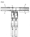
- the angle B (see figure 2 drum 12) between two channels of a pair - which can be defined as being the angle between the axis of the channels of a pair measured from the axis X of the channel- depends on the linear distance C (see figure 5 ) between the two long products before their entrance in each pair of channel. Said angle may be for example comprised between 14 and 24°, and preferably between 16 and 20°. In one embodiment B is equal to 18°.
- each drum 10 or 12 comprises a plurality of pair of channels as above defined.
- Each pair of channels is angularly spaced apart relative to the neighboring pair of channels by a predetermined angle ⁇ (with vertex the center X of the drum 10 or 12).
- This angle can be for example bigger than or equal to 30°.
- ⁇ can be preferably comprised between 30 and 45°.
- ⁇ is equal to 42°. Of course this angle depends on the diameter of the biggest product to be handled and on the maximal rotational speed of the drum.
- each pair of channels is angularly spaced apart relative to its neighboring channels by a portion free of channel.
- This portion has an angle ⁇ ' (with vertex the center X of the drum 10 or 12) which can be for example bigger or equal to 12° and preferably comprised between 12° and 18°. In one embodiment ⁇ ' is equal to 15°.
- each drum defines a plurality of longitudinal recesses 18.
- Each recess 18 has a pair of U shaped half tube, each U shaped half tube is a channel intended to receive a long product.
- the arrangement of the two channels (for example C1 and C2) part of a pair close to each other also allows the discharging of two long products on the same notch of the cooling bed 14 as can be seen on figures 3 and 6 .
- the channels of a pair have generally the same or a quite similar transversal cross section.
- each drum comprises between each pair of channel, for example between C1-C2 and C3-C4, a channel C1' having in a transversal cross section of said drum a shape different than the shape of the channels, for example C1-C4, part of a pair.
- each drum has two different types of channels with two different sizes.
- the channels with the first size are designed to receive long products with for example a diameter up to 16mm and the second size of channel, called big channels (for example C1'), are designed to receive long products with for example a diameter greater than 16mm up to for example 42mm.
- the angular width ⁇ and the depth "d" of each big channel are respectively greater than the angular width and the depth of each small channel.
- the different sizes of channels also allow to widen the range of long products which can be handled by a drum according to the invention in comparison to a known drum.
- the same drum can process different kinds of long products having a wide range of diameters.
- the fact that the sizes of the channels are adapted to the side of the product guaranties the stability of the product during its traveling within the channel.
- the long products introduced within the channel cause wear.
- the wear occurs in a channel designed for a long product having an important diameter, for example greater than 32mm, the wear changes the channel shape. This can lead to stoppage of subsequent long product having a smaller diameter using the same channel.
- This problem is avoided with the drum according to the invention because dedicated channels for small diameter long products and for bigger diameter long products are provided. In this way, all kinds of products are always well guided, even when a wear occurs in one of the channels.
- a drum according to this embodiment may allow to avoid the use of aprons normally needed upstream the cooling bed in the prior art solutions.
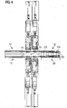
- FIG. 4 is a schematic view showing a system for handling a plurality of strands of long products preferably coming from a rolling mill according to the invention.
- this system comprises at least one drum 10 or 12. Upstream each drum 10 or 12 a guide 20 or 20'is provided.
- Each guide 20 or 20' has a "V" shape and comprises two spaced apart branches or entering portions 20a, 20b converging toward an ending branch or ending portion 20c.
- each spaced apart branch receives segments P1 or P2 of long product coming from two different strands of the rolling mill.
- Each branch 20a, 20b guides a long product segment toward the guide ending portion 20c where the two long product segments P1 and P2 are aligned in a parallel manner.
- each long product segment P1 and P2 is introduced simultaneously into a pair of channels of the drum by a breaking pinch roll 22 or 22'.
- the drum 10 or 12 according to the invention is arranged for and capable of cooperating with a system delivering simultaneously two parallel long products coming from two different strands of a rolling mill.
- each breaking pinch roll 22, 22' is a single groove pinch roll and is driven by one motor (not shown).
- a single double groove breaking pinch roll 24 or 24' is used to introduce both strands within the pair of channels 10 or 12, said pinch role 24 or 24' being driven by a sole motor (not shown).
- This embodiment may be used in cases where the available space is limited at this location of the plant.
- each drum is rotated step-wisely and delivers a pair of long products at time on the cooling bed or one big diameter long product at time on the cooling bed.
- the system according to invention comprises control means driving the rotation of the drum such that a pair of channel are facing the charging means 20, 22 and 22' and also synchronizing the pinch rolls breaking and the motions of the cooling bed to move forward the discharged long products.
- the two long products are aligned in a parallel manner by the exit section 20c of the guide 20 or 20'.
- the two long products are braked by the pinch rolls 22,22' and are introduced into a pair of channels of the drum 10 or 12 facing the pinch rolls.
- a fourth step the drum 10 or 12 is driven to rotate by one step such that two long product, which were previously confined in two chambers Ch closed by the cover 16 are discharged by gravity on the same notch of the cooling bed 14.
Landscapes
- Engineering & Computer Science (AREA)
- Mechanical Engineering (AREA)
- Metal Rolling (AREA)
- Rollers For Roller Conveyors For Transfer (AREA)
Description
- The invention concerns a method for handling rolled long products coming from different strands of a rolling mill see for example
IT 1225986 B - The invention may be used particularly, but not exclusively, in hot-rolling plants for the production of ferrous long products such as bars, rods or the like.
- In order to produce finished long metal products such as bar, rod or the like, a long metal plant comprises, among other devices, a plurality of rolling stands aligned along a rolling line to continuously roll billets received from a furnace or other like source.
- After the last rolling stand, the product is generally cut in bar segments which are subsequently cooled at ambient temperature, for example in a cooling bed.
- The long product can be discharged on the cooling bed by an apparatus called a drum.
- A long product production plant can be configured to process simultaneously a plurality of strands. The strands are obtained by dividing or slitting the product when still hot at a given point of the plant after a given number of rolling passes. The slitting is realized in order to increase the production rate of a plant without increasing rolling speed of the last stands. After this slitting operation, the long metal product is divided in different strands which need to be subsequently treated.
- In
document EP 1 8 77 203 B1 , in order to be able to process long products segments coming from different production strands, at least two drums per strand are provided. Each drum alternately receives one segment of the long product which has been previously cut. This means that two drums are allocated per strand of product. Furthermore switching means for directing the long product segments in the appropriate drum are needed. The above mentioned elements make the equipment rather complicated, increase its complexity and require a high amount of maintenance. - Document
WO 02 070156 A1 - A major objective of the invention is to simplify the handling of bars originating from different strands of a rolling mill before their loading on a cooling apparatus.
- A companion objective of the present invention is to diminish the number of drums, driving systems, and switches needed for handling bars segment coming from a plurality of strands.
- Another objective of the invention is to increase the production rate of a rolling mill plant, and to obtain a more compact plant.
- The above mentioned problems are solved by a method according to
claim 1. - The invention concerns a method for handling at least two long products preferably coming from two different strands of a rolling mill, characterized in that the method comprises the following steps:
- a) introducing said at least two long products in different channels of the same drum simultaneously and
- b) subsequently discharging said at least two long products on the same notch of a cooling bed.
- Advantageously prior to step a) the method comprises the following step:
- guiding said at least two long products to align said two long product in a parallel manner and,
- braking said at least two long products.
- According to other optional features of the invention taken alone or in combination:
- the drum comprises a plurality of pairs of channels, each pair of channels being spaced apart relative to the neighboring pairs of channels;
- each pair of channel is angularly spaced apart relative to the neighboring pairs of channels by an angle greater than or equal to 12 degrees and preferably comprised between 12 and 45°;
- the drum comprises a plurality of pairs of channels, each pair of channel being spaced apart relative to the neighboring channels by a portion free of channel; - said portion free of channel has an angular width α comprised between 12 and 18 degrees;
- the drum according comprises a plurality of pairs of channels wherein each channel of each pair of channels has a first size, and wherein the drum further comprises between each of said pairs of channels a channel having a second size different from the first size;
- the angular width and the depth of each channel having the second size are respectively greater than the angular width and the depth of each channel having the first size;
- each channel extends along a longitudinal axis parallel to the drum axis, and wherein the angularly distance between two axis of a pair of channel is bigger than or equal to 30°, and preferably comprised between 30° and 45° degrees;
- the angular distance between two channels of a pair depends on the linear distance between the two long products that the pair of channels is intended to receive;
- at least one cover intended to cooperate with each channel of said drum to form a chamber to momentarily confine each long product,
- at least one guide having at least two entry sections leading to a common exit section, the entry sections being intended to receive and guide at least two long products coming from two different strands of a rolling mill toward the exit section, and wherein the exit section face the entries of the channels of said drum and is intended to align in a parallel manner said at least two long products before their introduction into the channels of said drum,
- braking means for breaking said two parallel long products coming from said guide.
- The drum is able to handle simultaneously at least two bars in a simple manner and therefore minimize the number of drums needed to process multiple strands in a rolling mill plant.
- The drum is particularly advantageous in case where there is a plurality of strands coming from the rolling mill but can also be used where only one strand is produced.
- The teachings of the present invention can be readily understood by considering the following nonlimiting detailed description in conjunction with the accompanying drawings, in which:
-
FIG. 1 shows a transversal cross-section of drums located above a cooling bed, the drums being loaded with long products having a first diameter; -
FIG. 2 is an enlargement of afigure 1 ; -
FIG. 3 is a view similar tofigure 2 where the drums are loaded with long products having a second diameter; -
FIG. 4 is a schematic view of a first embodiment of a system for handling a plurality of strands of long products coming from a rolling mill; -
FIG. 5 is a schematic view of a second embodiment of a system for handling a plurality of strands of long products coming from a rolling mill; and -
FIG. 6 is a cross-sectional transversal view of second embodiment of drums. - To facilitate understanding, identical reference numerals have been used, where possible, to designate identical elements that are common to the figures.
- Further, as in a same drawing the drums are most of the time identical all reference numbers for one drum have not been reproduced twice for sake of clarity.
-
Figures 1 and2 show generally a couple ofdrums cooling bed 14. Eachdrum drum respective drum - As can be best seen on
figures 2 ,3 and6 each channel C1-Cn is designed to cyclically receive one long product P coming from a rolling mill at time. - Each drum also cooperates with a
cover 16 extending partially around and outside saiddrum cover 16 is arranged to momentarily close each channel C1-Cn and to form with each closed channel C1 to Cn a chamber Ch wherein each long metal product P is confined before being discharged onto thecooling bed 14. Eachcover 16 extends on a given angular segment with vertex the center X of thedrum - According to the invention, in order to be able to handle long products coming from different strands obtained for example thanks to a slitting process, each
drum - The angle B (see
figure 2 drum 12) between two channels of a pair - which can be defined as being the angle between the axis of the channels of a pair measured from the axis X of the channel- depends on the linear distance C (seefigure 5 ) between the two long products before their entrance in each pair of channel. Said angle may be for example comprised between 14 and 24°, and preferably between 16 and 20°. In one embodiment B is equal to 18°. - As can be seen on
figures 2 ,3 and6 eachdrum drum 10 or 12). This angle can be for example bigger than or equal to 30°. In the embodiment offigure 2 , α can be preferably comprised between 30 and 45°. In one embodiment α is equal to 42°. Of course this angle depends on the diameter of the biggest product to be handled and on the maximal rotational speed of the drum. - In the embodiment shown in
figure 6 , each pair of channels is angularly spaced apart relative to its neighboring channels by a portion free of channel. This portion has an angle α' (with vertex the center X of thedrum 10 or 12) which can be for example bigger or equal to 12° and preferably comprised between 12° and 18°. In one embodiment α' is equal to 15°. More precisely, each drum defines a plurality oflongitudinal recesses 18. Eachrecess 18 has a pair of U shaped half tube, each U shaped half tube is a channel intended to receive a long product. - The arrangement of the two channels (for example C1 and C2) part of a pair close to each other also allows the discharging of two long products on the same notch of the cooling
bed 14 as can be seen onfigures 3 and6 . - The channels of a pair have generally the same or a quite similar transversal cross section.
- In the embodiment shown on
figures 2 to 4 , each drum comprises between each pair of channel, for example between C1-C2 and C3-C4, a channel C1' having in a transversal cross section of said drum a shape different than the shape of the channels, for example C1-C4, part of a pair. In other words, in this embodiment, each drum has two different types of channels with two different sizes. - The channels with the first size, called small channels (for example C1-C4), are designed to receive long products with for example a diameter up to 16mm and the second size of channel, called big channels (for example C1'), are designed to receive long products with for example a diameter greater than 16mm up to for example 42mm. The angular width β and the depth "d" of each big channel are respectively greater than the angular width and the depth of each small channel.
- In addition to the fact that a drum according to the invention can process a plurality of strands at the same time, the different sizes of channels also allow to widen the range of long products which can be handled by a drum according to the invention in comparison to a known drum. In other words, thanks to this embodiment, the same drum can process different kinds of long products having a wide range of diameters.
- Furthermore, the fact that the sizes of the channels are adapted to the side of the product guaranties the stability of the product during its traveling within the channel.
- In addition, when traditional drums are used, the long products introduced within the channel cause wear. In case the wear occurs in a channel designed for a long product having an important diameter, for example greater than 32mm, the wear changes the channel shape. This can lead to stoppage of subsequent long product having a smaller diameter using the same channel. This problem is avoided with the drum according to the invention because dedicated channels for small diameter long products and for bigger diameter long products are provided. In this way, all kinds of products are always well guided, even when a wear occurs in one of the channels.
- Furthermore, under certain circumstances the use of a drum according to this embodiment may allow to avoid the use of aprons normally needed upstream the cooling bed in the prior art solutions.
-
Figure 4 is a schematic view showing a system for handling a plurality of strands of long products preferably coming from a rolling mill according to the invention. In a first embodiment, this system comprises at least onedrum drum 10 or 12 aguide 20 or 20'is provided. Eachguide 20 or 20' has a "V" shape and comprises two spaced apart branches or enteringportions portion 20c. During operation of the rolling mill, each spaced apart branch receives segments P1 or P2 of long product coming from two different strands of the rolling mill. Eachbranch guide ending portion 20c where the two long product segments P1 and P2 are aligned in a parallel manner. Subsequently, each long product segment P1 and P2 is introduced simultaneously into a pair of channels of the drum by a breakingpinch roll 22 or 22'. - As above shown, the
drum - In the embodiment shown in
figure 4 , each breakingpinch roll 22, 22'is a single groove pinch roll and is driven by one motor (not shown). - In the embodiment shown in
figure 5 , a single double groove breakingpinch roll 24 or 24' is used to introduce both strands within the pair ofchannels pinch role 24 or 24' being driven by a sole motor (not shown). This embodiment may be used in cases where the available space is limited at this location of the plant. - As can be seen in
figures 2 ,3 and6 , after introduction of a pair of small diameter long products, or of one big diameter long product, each drum is rotated step-wisely and delivers a pair of long products at time on the cooling bed or one big diameter long product at time on the cooling bed. - Even if not shown, it will be understood that the system according to invention comprises control means driving the rotation of the drum such that a pair of channel are facing the charging means 20, 22 and 22' and also synchronizing the pinch rolls breaking and the motions of the cooling bed to move forward the discharged long products.
- When two long products coming from two different strands of a rolling mill arrive in the handling system (driven by upstream pinch rolls not shown on the figures) according to the invention, they are in a first step guided by the two
entry sections guide 20 or 20'. - In a second step, the two long products are aligned in a parallel manner by the
exit section 20c of theguide 20 or 20'. - In a third step, the two long products are braked by the pinch rolls 22,22' and are introduced into a pair of channels of the
drum - In a fourth step, the
drum cover 16 are discharged by gravity on the same notch of the coolingbed 14.
[
Claims (13)
- Method for handling at least two long products (P1,P2) preferably coming from two different strands of a rolling mill, characterized in that the method comprises the following steps:
the method comprising the step of:- a) introducing said at least two long products in different channels of the same drum (10,12) simultaneously,- b) subsequently discharging said at least two long products on the same notch of a cooling bed (14). - Method according to claim 1 comprising prior to step a):- guiding said at least two long products to align said two long product in a parallel manner and,- braking said at least two long products.
- Method according the previous claims wherein said drum comprising at least one pair of circumferential channels (C1-C2) extending parallel to the drum axis (X), said at least one pair of channels being arranged to receive simultaneously two long products (P1,P2), respectively one long product in each one of the channels part of the pair, said at least one pair of channels is arranged to subsequently discharge said at least two long products on the same notch of the cooling bed (14).
- Method according to claim 3 wherein said drum comprising a plurality of pairs of channels (C1-C2, C3-C4), each pair of channels being spaced apart relative to the neighboring pairs of channels.
- Method according to claim 4 wherein each pair of channels (C1-C2, C3-C4) is angularly spaced apart relative to the neighboring pairs of channels by an angle (α, α') greater than or equal to 12 degrees and preferably comprised between 12 and 45°.
- Method according to claims 3 to 5 wherein said drum comprising a plurality of pairs of channels (C1-C2, C3-C4), each pair of channel being spaced apart relative to the neighboring channels by a portion free of channel.
- Method according to the previous claim wherein said portion free of channel has an angular width α comprised between 12 and 18 degrees.
- Method according to claims 3 to 5 wherein said drum comprising a plurality of pairs of channels (C1-C2, C3-C4) wherein each channel of each pair of channels has a first size, and wherein the drum further comprises between each of said pairs of channels a channel (C1') having a second size different from the first size.
- Method according to the previous claim wherein the angular width (β) and the depth (d) of each channel having the second size are respectively greater than the angular width and the depth of each channel having the first size.
- Method according to anyone of the previous claims 3 to 9 wherein each channel extends along a longitudinal axis parallel to the drum axis (X), and wherein the angularly distance between two axis of a pair of channel is bigger than or equal to 30°, and preferably comprised between 30° and 45° degrees.
- Method according to anyone of the previous claims 3 to 10 wherein the angular distance (B) between two channels of a pair depends on the linear distance (C) between the two long products that the pair of channels is intended to receive.
- Method according to anyone of the previous claims 3 to 11 wherein the angle B between two channels of a pair is comprised between 14 and 24°, and preferably between 16 and 20°.
- Method according to anyone of the previous claims 3 to 12 further using- at least one cover (16) intended to cooperate with each channel (C1-Cn) of said drum to form a chamber (Ch) to momentarily confine each long product,- at least one guide (20, 20') having at least two entry sections (20a, 20b) leading to a common exit section (20c), the entry sections being intended to receive and guide at least two long products (P1,P2) coming from two different strands of a rolling mill toward the exit section, and wherein the exit section (20c) face the entries of the channels of said drum and is intended to align in a parallel manner said at least two long products before their introduction into the channels of said drum,- braking means for breaking said two parallel long products coming from said guide.
Priority Applications (10)
| Application Number | Priority Date | Filing Date | Title |
|---|---|---|---|
| ES13425097T ES2570363T5 (en) | 2013-07-05 | 2013-07-05 | Procedure for handling long rolled products from different lines of a rolling train |
| PL13425097.6T PL2821154T5 (en) | 2013-07-05 | 2013-07-05 | Apparatus, system and method for handling long rolled products coming from different strands of a rolling mill |
| EP13425097.6A EP2821154B2 (en) | 2013-07-05 | 2013-07-05 | Method for handling long rolled products coming from different strands of a rolling mill |
| US14/902,994 US9724741B2 (en) | 2013-07-05 | 2014-06-26 | Drum, system and method for handling long rolled products coming from different strands of a rolling mill |
| RU2016103629A RU2696122C2 (en) | 2013-07-05 | 2014-06-26 | Drum, system and method for handling long rolled products coming from different sections of rolling mill |
| BR112015032934-9A BR112015032934B1 (en) | 2013-07-05 | 2014-06-26 | DRUM FOR RECEIVING, TRANSPORTING AND UNLOADING LONG METALLIC PRODUCTS, SYSTEM FOR HANDLING A MULTITUDE OF LONG PRODUCTS AND METHOD FOR HANDLING AT LEAST TWO LONG PRODUCTS |
| PCT/EP2014/063487 WO2015000780A1 (en) | 2013-07-05 | 2014-06-26 | Drum, system and method for handling long rolled products coming from different strands of a rolling mill |
| CN201910575608.XA CN110280698B (en) | 2013-07-05 | 2014-06-26 | Method for treating long rolled products from different strands of a rolling mill |
| CN201480038241.3A CN105517721A (en) | 2013-07-05 | 2014-06-26 | Drum, system and method for processing long rolls of different strands from a rolling mill |
| JP2016522492A JP6199488B2 (en) | 2013-07-05 | 2014-06-26 | Drum, system and method for processing long rolled products conveyed from different strands of a rolling mill |
Applications Claiming Priority (1)
| Application Number | Priority Date | Filing Date | Title |
|---|---|---|---|
| EP13425097.6A EP2821154B2 (en) | 2013-07-05 | 2013-07-05 | Method for handling long rolled products coming from different strands of a rolling mill |
Publications (3)
| Publication Number | Publication Date |
|---|---|
| EP2821154A1 EP2821154A1 (en) | 2015-01-07 |
| EP2821154B1 EP2821154B1 (en) | 2016-04-06 |
| EP2821154B2 true EP2821154B2 (en) | 2022-05-25 |
Family
ID=49226104
Family Applications (1)
| Application Number | Title | Priority Date | Filing Date |
|---|---|---|---|
| EP13425097.6A Active EP2821154B2 (en) | 2013-07-05 | 2013-07-05 | Method for handling long rolled products coming from different strands of a rolling mill |
Country Status (9)
| Country | Link |
|---|---|
| US (1) | US9724741B2 (en) |
| EP (1) | EP2821154B2 (en) |
| JP (1) | JP6199488B2 (en) |
| CN (2) | CN110280698B (en) |
| BR (1) | BR112015032934B1 (en) |
| ES (1) | ES2570363T5 (en) |
| PL (1) | PL2821154T5 (en) |
| RU (1) | RU2696122C2 (en) |
| WO (1) | WO2015000780A1 (en) |
Families Citing this family (5)
| Publication number | Priority date | Publication date | Assignee | Title |
|---|---|---|---|---|
| IT201900003501A1 (en) * | 2019-03-11 | 2020-09-11 | Primetals Tech Italy S R L | Gap control method and system in rolling mills |
| CN111204554A (en) * | 2019-09-27 | 2020-05-29 | 广西科技大学 | Automatic blanking mechanism for clamping piece sawing process |
| CN110976528B (en) * | 2019-12-18 | 2022-06-17 | 攀枝花钢城集团有限公司 | Sorting control method for multiple-length steel products on cooling bed |
| CN112340431A (en) * | 2020-12-09 | 2021-02-09 | 青岛双清智能科技有限公司 | Basket placing mechanism |
| CN112917219B (en) * | 2021-01-28 | 2022-02-01 | 金华洛为科技有限公司 | Automatic feeding device of numerical control cutting machine |
Citations (1)
| Publication number | Priority date | Publication date | Assignee | Title |
|---|---|---|---|---|
| US3497084A (en) † | 1968-02-28 | 1970-02-24 | Morgan Construction Co | Means for counting,bundling and weighing of elongated elements |
Family Cites Families (18)
| Publication number | Priority date | Publication date | Assignee | Title |
|---|---|---|---|---|
| SE329823B (en) * | 1968-08-27 | 1970-10-26 | Morgaardshammar Ab | |
| SU274769A2 (en) | 1969-04-07 | 2007-04-20 | Электростальский Завод Тяжелого Машиностроения | DRUM TYPE EXTRACTOR |
| JPS51133164A (en) * | 1975-05-15 | 1976-11-18 | Kobe Steel Ltd | Device for guiding rolling material |
| IT1051129B (en) | 1975-10-13 | 1981-04-21 | Simac Spa | DOUBLE ROTARY CHANNEL DEVICE FOR THE AXIAL RECEPTION OF LAMINATED AND SIMILAR BARS AND THEIR TRANSVERSAL DISCHARGE AND METO DO BELATIVO |
| IT1225986B (en) | 1988-10-04 | 1990-12-10 | Simac Spa | Method and installation for cropping and despatch to the cooling plate of pairs of bars/rolled wire in parallel |
| EP0553930B1 (en) * | 1992-01-31 | 1996-04-17 | POMINI S.p.A. | Bar receiving and discharging device |
| JPH0610227U (en) * | 1992-07-15 | 1994-02-08 | 日立造船株式会社 | Scrap dispensing device |
| IT1262170B (en) | 1993-07-30 | 1996-06-19 | Danieli Off Mecc | RECEPTION AND MULTIPLE DISCHARGE PROCEDURE OF LAMINATED PROFILES IN COOLING PLATE AND DEVICE REALIZING SUCH PROCEDURE |
| IT1283418B1 (en) | 1996-07-10 | 1998-04-21 | Pomini Spa | AUTOMATIC STACKER WITH ROTATING HEADS FOR STACKING METALLIC PROFILES IN ALTERNATIVE LAYERS, STRAIGHT AND REVERSE, ORDERLY |
| IT1290710B1 (en) | 1997-01-21 | 1998-12-10 | Simac Spa | METHOD OF RECEIVING AND UNLOADING BARS AND ROTARY CHANNEL DEVICE WITH PAIR OF ADJACENT PARALLEL ROTATING DRUMS |
| US6192729B1 (en) * | 1998-01-16 | 2001-02-27 | S.I.M.A.C. S.P.A. | Method and apparatus for receiving and discharging bars |
| ITUD20010048A1 (en) | 2001-03-08 | 2002-09-08 | Simac Spa | BAR RECEIVING AND UNLOADING DEVICE AND THE RESPECTIVE SYSTEM PARTICULARLY FOR HANDLING AND / OR PACKING DOWNSTREAM SYSTEMS D |
| ITMI20041210A1 (en) | 2004-06-16 | 2004-09-16 | Danieli Off Mecc | BAR PACKAGING APPARATUS AND RELATED METHOD |
| ITMI20050315A1 (en) | 2005-03-02 | 2006-09-03 | Danieli Off Mecc | COMPACT PLANT FOR THE CONTINUOUS PRODUCTION OF E-O PROFILE BARS |
| ITUD20050113A1 (en) | 2005-07-04 | 2007-01-05 | Sms Meer Spa | SYSTEM FOR RECEIPT AND CONVEYANCE OF BARS COMING FROM MILLS TOWARDS A COLLECTION AND UNLOADING DEVICE |
| US7219521B1 (en) | 2006-09-19 | 2007-05-22 | Morgan Construction Company | Rolling mill product handling system |
| US20130074567A1 (en) | 2011-09-23 | 2013-03-28 | Siemens Industry, Inc. | Rotating entry system with front end or front and rear drive system |
| ITVI20120001A1 (en) * | 2012-01-03 | 2013-07-04 | Sms Meer Spa | PLANT FOR THE PRODUCTION AND PACKAGING OF BARS AND STEEL PROFILES |
-
2013
- 2013-07-05 EP EP13425097.6A patent/EP2821154B2/en active Active
- 2013-07-05 ES ES13425097T patent/ES2570363T5/en active Active
- 2013-07-05 PL PL13425097.6T patent/PL2821154T5/en unknown
-
2014
- 2014-06-26 JP JP2016522492A patent/JP6199488B2/en active Active
- 2014-06-26 WO PCT/EP2014/063487 patent/WO2015000780A1/en not_active Ceased
- 2014-06-26 BR BR112015032934-9A patent/BR112015032934B1/en active IP Right Grant
- 2014-06-26 CN CN201910575608.XA patent/CN110280698B/en active Active
- 2014-06-26 CN CN201480038241.3A patent/CN105517721A/en active Pending
- 2014-06-26 RU RU2016103629A patent/RU2696122C2/en active
- 2014-06-26 US US14/902,994 patent/US9724741B2/en active Active
Patent Citations (1)
| Publication number | Priority date | Publication date | Assignee | Title |
|---|---|---|---|---|
| US3497084A (en) † | 1968-02-28 | 1970-02-24 | Morgan Construction Co | Means for counting,bundling and weighing of elongated elements |
Also Published As
| Publication number | Publication date |
|---|---|
| CN110280698A (en) | 2019-09-27 |
| CN110280698B (en) | 2022-06-07 |
| JP2016528041A (en) | 2016-09-15 |
| BR112015032934B1 (en) | 2023-01-17 |
| RU2016103629A (en) | 2017-08-10 |
| JP6199488B2 (en) | 2017-09-20 |
| EP2821154B1 (en) | 2016-04-06 |
| CN105517721A (en) | 2016-04-20 |
| EP2821154A1 (en) | 2015-01-07 |
| ES2570363T3 (en) | 2016-05-18 |
| WO2015000780A1 (en) | 2015-01-08 |
| RU2016103629A3 (en) | 2018-03-29 |
| ES2570363T5 (en) | 2022-09-12 |
| PL2821154T3 (en) | 2016-09-30 |
| US9724741B2 (en) | 2017-08-08 |
| BR112015032934A2 (en) | 2017-07-25 |
| PL2821154T5 (en) | 2023-02-27 |
| US20160151816A1 (en) | 2016-06-02 |
| RU2696122C2 (en) | 2019-07-31 |
Similar Documents
| Publication | Publication Date | Title |
|---|---|---|
| EP2821154B2 (en) | Method for handling long rolled products coming from different strands of a rolling mill | |
| AT514079B1 (en) | Method and device for rapid removal of heavy plates from a rolling mill | |
| UA78248C2 (en) | Method and casting/rolling mill for producing steel strip | |
| US8046901B2 (en) | Compact plant for continuous production of bars and/or profiles | |
| CA2448784C (en) | Bar delivery system and method | |
| US6763561B2 (en) | Continuous casting and hot rolling apparatus for parallel production of multiple metal shapes | |
| US3942350A (en) | Rolling mill train for the production of wire | |
| US6035682A (en) | Method and respective hot rolling-mill plant for the continuous production of bars, rods or wire | |
| US20190275574A1 (en) | Plant for the production and the packaging of steel bars or rods | |
| US6647604B2 (en) | Continuous casting and rolling of multiple rods | |
| EP1958709B1 (en) | Multiple outlet rolling mill | |
| EP2821153B1 (en) | System and method for cutting to length long rolled products coming from different strands of a rolling mill | |
| SU961807A1 (en) | Rolling mill for producing metal bars and rods | |
| US7069759B2 (en) | Bar delivery system and method | |
| JP5633203B2 (en) | Multi-strand rolling equipment for bar wire equipped with sorting device and billet sorting method |
Legal Events
| Date | Code | Title | Description |
|---|---|---|---|
| PUAI | Public reference made under article 153(3) epc to a published international application that has entered the european phase |
Free format text: ORIGINAL CODE: 0009012 |
|
| 17P | Request for examination filed |
Effective date: 20130705 |
|
| AK | Designated contracting states |
Kind code of ref document: A1 Designated state(s): AL AT BE BG CH CY CZ DE DK EE ES FI FR GB GR HR HU IE IS IT LI LT LU LV MC MK MT NL NO PL PT RO RS SE SI SK SM TR |
|
| AX | Request for extension of the european patent |
Extension state: BA ME |
|
| RAP1 | Party data changed (applicant data changed or rights of an application transferred) |
Owner name: PRIMETALS TECHNOLOGIES AUSTRIA GMBH |
|
| R17P | Request for examination filed (corrected) |
Effective date: 20150618 |
|
| RBV | Designated contracting states (corrected) |
Designated state(s): AL AT BE BG CH CY CZ DE DK EE ES FI FR GB GR HR HU IE IS IT LI LT LU LV MC MK MT NL NO PL PT RO RS SE SI SK SM TR |
|
| GRAP | Despatch of communication of intention to grant a patent |
Free format text: ORIGINAL CODE: EPIDOSNIGR1 |
|
| RIC1 | Information provided on ipc code assigned before grant |
Ipc: B21C 47/34 20060101ALI20151023BHEP Ipc: B21B 43/00 20060101AFI20151023BHEP |
|
| INTG | Intention to grant announced |
Effective date: 20151130 |
|
| GRAS | Grant fee paid |
Free format text: ORIGINAL CODE: EPIDOSNIGR3 |
|
| GRAA | (expected) grant |
Free format text: ORIGINAL CODE: 0009210 |
|
| AK | Designated contracting states |
Kind code of ref document: B1 Designated state(s): AL AT BE BG CH CY CZ DE DK EE ES FI FR GB GR HR HU IE IS IT LI LT LU LV MC MK MT NL NO PL PT RO RS SE SI SK SM TR |
|
| REG | Reference to a national code |
Ref country code: GB Ref legal event code: FG4D |
|
| REG | Reference to a national code |
Ref country code: AT Ref legal event code: REF Ref document number: 787171 Country of ref document: AT Kind code of ref document: T Effective date: 20160415 Ref country code: CH Ref legal event code: EP |
|
| REG | Reference to a national code |
Ref country code: IE Ref legal event code: FG4D |
|
| REG | Reference to a national code |
Ref country code: ES Ref legal event code: FG2A Ref document number: 2570363 Country of ref document: ES Kind code of ref document: T3 Effective date: 20160518 |
|
| REG | Reference to a national code |
Ref country code: DE Ref legal event code: R096 Ref document number: 602013006180 Country of ref document: DE |
|
| REG | Reference to a national code |
Ref country code: FR Ref legal event code: PLFP Year of fee payment: 4 |
|
| REG | Reference to a national code |
Ref country code: LT Ref legal event code: MG4D Ref country code: NL Ref legal event code: MP Effective date: 20160406 |
|
| REG | Reference to a national code |
Ref country code: AT Ref legal event code: MK05 Ref document number: 787171 Country of ref document: AT Kind code of ref document: T Effective date: 20160406 |
|
| PG25 | Lapsed in a contracting state [announced via postgrant information from national office to epo] |
Ref country code: NL Free format text: LAPSE BECAUSE OF FAILURE TO SUBMIT A TRANSLATION OF THE DESCRIPTION OR TO PAY THE FEE WITHIN THE PRESCRIBED TIME-LIMIT Effective date: 20160406 |
|
| PG25 | Lapsed in a contracting state [announced via postgrant information from national office to epo] |
Ref country code: IS Free format text: LAPSE BECAUSE OF FAILURE TO SUBMIT A TRANSLATION OF THE DESCRIPTION OR TO PAY THE FEE WITHIN THE PRESCRIBED TIME-LIMIT Effective date: 20160806 Ref country code: LT Free format text: LAPSE BECAUSE OF FAILURE TO SUBMIT A TRANSLATION OF THE DESCRIPTION OR TO PAY THE FEE WITHIN THE PRESCRIBED TIME-LIMIT Effective date: 20160406 Ref country code: FI Free format text: LAPSE BECAUSE OF FAILURE TO SUBMIT A TRANSLATION OF THE DESCRIPTION OR TO PAY THE FEE WITHIN THE PRESCRIBED TIME-LIMIT Effective date: 20160406 Ref country code: NO Free format text: LAPSE BECAUSE OF FAILURE TO SUBMIT A TRANSLATION OF THE DESCRIPTION OR TO PAY THE FEE WITHIN THE PRESCRIBED TIME-LIMIT Effective date: 20160706 |
|
| PG25 | Lapsed in a contracting state [announced via postgrant information from national office to epo] |
Ref country code: PT Free format text: LAPSE BECAUSE OF FAILURE TO SUBMIT A TRANSLATION OF THE DESCRIPTION OR TO PAY THE FEE WITHIN THE PRESCRIBED TIME-LIMIT Effective date: 20160808 Ref country code: SE Free format text: LAPSE BECAUSE OF FAILURE TO SUBMIT A TRANSLATION OF THE DESCRIPTION OR TO PAY THE FEE WITHIN THE PRESCRIBED TIME-LIMIT Effective date: 20160406 Ref country code: HR Free format text: LAPSE BECAUSE OF FAILURE TO SUBMIT A TRANSLATION OF THE DESCRIPTION OR TO PAY THE FEE WITHIN THE PRESCRIBED TIME-LIMIT Effective date: 20160406 Ref country code: AT Free format text: LAPSE BECAUSE OF FAILURE TO SUBMIT A TRANSLATION OF THE DESCRIPTION OR TO PAY THE FEE WITHIN THE PRESCRIBED TIME-LIMIT Effective date: 20160406 Ref country code: LV Free format text: LAPSE BECAUSE OF FAILURE TO SUBMIT A TRANSLATION OF THE DESCRIPTION OR TO PAY THE FEE WITHIN THE PRESCRIBED TIME-LIMIT Effective date: 20160406 Ref country code: RS Free format text: LAPSE BECAUSE OF FAILURE TO SUBMIT A TRANSLATION OF THE DESCRIPTION OR TO PAY THE FEE WITHIN THE PRESCRIBED TIME-LIMIT Effective date: 20160406 Ref country code: GR Free format text: LAPSE BECAUSE OF FAILURE TO SUBMIT A TRANSLATION OF THE DESCRIPTION OR TO PAY THE FEE WITHIN THE PRESCRIBED TIME-LIMIT Effective date: 20160707 |
|
| PG25 | Lapsed in a contracting state [announced via postgrant information from national office to epo] |
Ref country code: BE Free format text: LAPSE BECAUSE OF FAILURE TO SUBMIT A TRANSLATION OF THE DESCRIPTION OR TO PAY THE FEE WITHIN THE PRESCRIBED TIME-LIMIT Effective date: 20160406 |
|
| REG | Reference to a national code |
Ref country code: DE Ref legal event code: R026 Ref document number: 602013006180 Country of ref document: DE |
|
| PLBI | Opposition filed |
Free format text: ORIGINAL CODE: 0009260 |
|
| PLAB | Opposition data, opponent's data or that of the opponent's representative modified |
Free format text: ORIGINAL CODE: 0009299OPPO |
|
| PG25 | Lapsed in a contracting state [announced via postgrant information from national office to epo] |
Ref country code: SK Free format text: LAPSE BECAUSE OF FAILURE TO SUBMIT A TRANSLATION OF THE DESCRIPTION OR TO PAY THE FEE WITHIN THE PRESCRIBED TIME-LIMIT Effective date: 20160406 Ref country code: CZ Free format text: LAPSE BECAUSE OF FAILURE TO SUBMIT A TRANSLATION OF THE DESCRIPTION OR TO PAY THE FEE WITHIN THE PRESCRIBED TIME-LIMIT Effective date: 20160406 Ref country code: RO Free format text: LAPSE BECAUSE OF FAILURE TO SUBMIT A TRANSLATION OF THE DESCRIPTION OR TO PAY THE FEE WITHIN THE PRESCRIBED TIME-LIMIT Effective date: 20160406 Ref country code: EE Free format text: LAPSE BECAUSE OF FAILURE TO SUBMIT A TRANSLATION OF THE DESCRIPTION OR TO PAY THE FEE WITHIN THE PRESCRIBED TIME-LIMIT Effective date: 20160406 Ref country code: DK Free format text: LAPSE BECAUSE OF FAILURE TO SUBMIT A TRANSLATION OF THE DESCRIPTION OR TO PAY THE FEE WITHIN THE PRESCRIBED TIME-LIMIT Effective date: 20160406 |
|
| 26 | Opposition filed |
Opponent name: DANIELI & C. OFFICINE MECCANICHE SPA Effective date: 20170105 |
|
| PLAX | Notice of opposition and request to file observation + time limit sent |
Free format text: ORIGINAL CODE: EPIDOSNOBS2 |
|
| R26 | Opposition filed (corrected) |
Opponent name: DANIELI & C. OFFICINE MECCANICHE S.P.A. Effective date: 20170105 |
|
| PG25 | Lapsed in a contracting state [announced via postgrant information from national office to epo] |
Ref country code: SM Free format text: LAPSE BECAUSE OF FAILURE TO SUBMIT A TRANSLATION OF THE DESCRIPTION OR TO PAY THE FEE WITHIN THE PRESCRIBED TIME-LIMIT Effective date: 20160406 |
|
| REG | Reference to a national code |
Ref country code: CH Ref legal event code: PL |
|
| PG25 | Lapsed in a contracting state [announced via postgrant information from national office to epo] |
Ref country code: MC Free format text: LAPSE BECAUSE OF FAILURE TO SUBMIT A TRANSLATION OF THE DESCRIPTION OR TO PAY THE FEE WITHIN THE PRESCRIBED TIME-LIMIT Effective date: 20160406 |
|
| PG25 | Lapsed in a contracting state [announced via postgrant information from national office to epo] |
Ref country code: LI Free format text: LAPSE BECAUSE OF NON-PAYMENT OF DUE FEES Effective date: 20160731 Ref country code: CH Free format text: LAPSE BECAUSE OF NON-PAYMENT OF DUE FEES Effective date: 20160731 |
|
| REG | Reference to a national code |
Ref country code: IE Ref legal event code: MM4A |
|
| PG25 | Lapsed in a contracting state [announced via postgrant information from national office to epo] |
Ref country code: SI Free format text: LAPSE BECAUSE OF FAILURE TO SUBMIT A TRANSLATION OF THE DESCRIPTION OR TO PAY THE FEE WITHIN THE PRESCRIBED TIME-LIMIT Effective date: 20160406 |
|
| PLBB | Reply of patent proprietor to notice(s) of opposition received |
Free format text: ORIGINAL CODE: EPIDOSNOBS3 |
|
| REG | Reference to a national code |
Ref country code: FR Ref legal event code: PLFP Year of fee payment: 5 |
|
| PG25 | Lapsed in a contracting state [announced via postgrant information from national office to epo] |
Ref country code: IE Free format text: LAPSE BECAUSE OF NON-PAYMENT OF DUE FEES Effective date: 20160705 |
|
| PG25 | Lapsed in a contracting state [announced via postgrant information from national office to epo] |
Ref country code: LU Free format text: LAPSE BECAUSE OF NON-PAYMENT OF DUE FEES Effective date: 20160705 |
|
| PG25 | Lapsed in a contracting state [announced via postgrant information from national office to epo] |
Ref country code: HU Free format text: LAPSE BECAUSE OF FAILURE TO SUBMIT A TRANSLATION OF THE DESCRIPTION OR TO PAY THE FEE WITHIN THE PRESCRIBED TIME-LIMIT; INVALID AB INITIO Effective date: 20130705 |
|
| PG25 | Lapsed in a contracting state [announced via postgrant information from national office to epo] |
Ref country code: MT Free format text: LAPSE BECAUSE OF NON-PAYMENT OF DUE FEES Effective date: 20160731 Ref country code: CY Free format text: LAPSE BECAUSE OF FAILURE TO SUBMIT A TRANSLATION OF THE DESCRIPTION OR TO PAY THE FEE WITHIN THE PRESCRIBED TIME-LIMIT Effective date: 20160406 Ref country code: MK Free format text: LAPSE BECAUSE OF FAILURE TO SUBMIT A TRANSLATION OF THE DESCRIPTION OR TO PAY THE FEE WITHIN THE PRESCRIBED TIME-LIMIT Effective date: 20160406 |
|
| REG | Reference to a national code |
Ref country code: FR Ref legal event code: PLFP Year of fee payment: 6 |
|
| PG25 | Lapsed in a contracting state [announced via postgrant information from national office to epo] |
Ref country code: BG Free format text: LAPSE BECAUSE OF FAILURE TO SUBMIT A TRANSLATION OF THE DESCRIPTION OR TO PAY THE FEE WITHIN THE PRESCRIBED TIME-LIMIT Effective date: 20160406 |
|
| PG25 | Lapsed in a contracting state [announced via postgrant information from national office to epo] |
Ref country code: AL Free format text: LAPSE BECAUSE OF FAILURE TO SUBMIT A TRANSLATION OF THE DESCRIPTION OR TO PAY THE FEE WITHIN THE PRESCRIBED TIME-LIMIT Effective date: 20160406 |
|
| APBM | Appeal reference recorded |
Free format text: ORIGINAL CODE: EPIDOSNREFNO |
|
| APBP | Date of receipt of notice of appeal recorded |
Free format text: ORIGINAL CODE: EPIDOSNNOA2O |
|
| APAH | Appeal reference modified |
Free format text: ORIGINAL CODE: EPIDOSCREFNO |
|
| APBQ | Date of receipt of statement of grounds of appeal recorded |
Free format text: ORIGINAL CODE: EPIDOSNNOA3O |
|
| APBU | Appeal procedure closed |
Free format text: ORIGINAL CODE: EPIDOSNNOA9O |
|
| PUAH | Patent maintained in amended form |
Free format text: ORIGINAL CODE: 0009272 |
|
| STAA | Information on the status of an ep patent application or granted ep patent |
Free format text: STATUS: PATENT MAINTAINED AS AMENDED |
|
| 27A | Patent maintained in amended form |
Effective date: 20220525 |
|
| AK | Designated contracting states |
Kind code of ref document: B2 Designated state(s): AL AT BE BG CH CY CZ DE DK EE ES FI FR GB GR HR HU IE IS IT LI LT LU LV MC MK MT NL NO PL PT RO RS SE SI SK SM TR |
|
| REG | Reference to a national code |
Ref country code: DE Ref legal event code: R102 Ref document number: 602013006180 Country of ref document: DE |
|
| REG | Reference to a national code |
Ref country code: ES Ref legal event code: DC2A Ref document number: 2570363 Country of ref document: ES Kind code of ref document: T5 Effective date: 20220912 |
|
| REG | Reference to a national code |
Ref country code: DE Ref legal event code: R082 Ref document number: 602013006180 Country of ref document: DE Representative=s name: LINDNER BLAUMEIER, PATENT- UND RECHTSANWAELTE,, DE |
|
| PGFP | Annual fee paid to national office [announced via postgrant information from national office to epo] |
Ref country code: TR Payment date: 20250630 Year of fee payment: 13 |
|
| PGFP | Annual fee paid to national office [announced via postgrant information from national office to epo] |
Ref country code: ES Payment date: 20250826 Year of fee payment: 13 |
|
| PGFP | Annual fee paid to national office [announced via postgrant information from national office to epo] |
Ref country code: DE Payment date: 20250722 Year of fee payment: 13 |
|
| PGFP | Annual fee paid to national office [announced via postgrant information from national office to epo] |
Ref country code: PL Payment date: 20250627 Year of fee payment: 13 Ref country code: IT Payment date: 20250724 Year of fee payment: 13 |
|
| PGFP | Annual fee paid to national office [announced via postgrant information from national office to epo] |
Ref country code: GB Payment date: 20250722 Year of fee payment: 13 |
|
| PGFP | Annual fee paid to national office [announced via postgrant information from national office to epo] |
Ref country code: FR Payment date: 20250725 Year of fee payment: 13 |