EP2800245A1 - Elektrischer Antrieb eines KfZ-Aggregats - Google Patents
Elektrischer Antrieb eines KfZ-Aggregats Download PDFInfo
- Publication number
- EP2800245A1 EP2800245A1 EP13166034.2A EP13166034A EP2800245A1 EP 2800245 A1 EP2800245 A1 EP 2800245A1 EP 13166034 A EP13166034 A EP 13166034A EP 2800245 A1 EP2800245 A1 EP 2800245A1
- Authority
- EP
- European Patent Office
- Prior art keywords
- motor
- shaft
- motor rotor
- vehicle unit
- stator
- Prior art date
- Legal status (The legal status is an assumption and is not a legal conclusion. Google has not performed a legal analysis and makes no representation as to the accuracy of the status listed.)
- Withdrawn
Links
- 230000005291 magnetic effect Effects 0.000 claims abstract description 23
- 230000005294 ferromagnetic effect Effects 0.000 description 6
- 238000003780 insertion Methods 0.000 description 3
- 230000037431 insertion Effects 0.000 description 3
- XEEYBQQBJWHFJM-UHFFFAOYSA-N Iron Chemical compound [Fe] XEEYBQQBJWHFJM-UHFFFAOYSA-N 0.000 description 2
- 238000002485 combustion reaction Methods 0.000 description 2
- 239000002923 metal particle Substances 0.000 description 2
- 230000005540 biological transmission Effects 0.000 description 1
- 239000011248 coating agent Substances 0.000 description 1
- 238000000576 coating method Methods 0.000 description 1
- 239000002826 coolant Substances 0.000 description 1
- 230000005684 electric field Effects 0.000 description 1
- 238000001746 injection moulding Methods 0.000 description 1
- 238000009434 installation Methods 0.000 description 1
- 230000003993 interaction Effects 0.000 description 1
- 229910052742 iron Inorganic materials 0.000 description 1
- 239000000314 lubricant Substances 0.000 description 1
- 239000000696 magnetic material Substances 0.000 description 1
- 229910001092 metal group alloy Inorganic materials 0.000 description 1
- 238000000034 method Methods 0.000 description 1
- 238000006748 scratching Methods 0.000 description 1
- 230000002393 scratching effect Effects 0.000 description 1
- 239000011343 solid material Substances 0.000 description 1
Images

Classifications
-
- H—ELECTRICITY
- H02—GENERATION; CONVERSION OR DISTRIBUTION OF ELECTRIC POWER
- H02K—DYNAMO-ELECTRIC MACHINES
- H02K1/00—Details of the magnetic circuit
- H02K1/06—Details of the magnetic circuit characterised by the shape, form or construction
- H02K1/22—Rotating parts of the magnetic circuit
- H02K1/27—Rotor cores with permanent magnets
- H02K1/2706—Inner rotors
-
- F—MECHANICAL ENGINEERING; LIGHTING; HEATING; WEAPONS; BLASTING
- F02—COMBUSTION ENGINES; HOT-GAS OR COMBUSTION-PRODUCT ENGINE PLANTS
- F02D—CONTROLLING COMBUSTION ENGINES
- F02D11/00—Arrangements for, or adaptations to, non-automatic engine control initiation means, e.g. operator initiated
- F02D11/06—Arrangements for, or adaptations to, non-automatic engine control initiation means, e.g. operator initiated characterised by non-mechanical control linkages, e.g. fluid control linkages or by control linkages with power drive or assistance
- F02D11/10—Arrangements for, or adaptations to, non-automatic engine control initiation means, e.g. operator initiated characterised by non-mechanical control linkages, e.g. fluid control linkages or by control linkages with power drive or assistance of the electric type
-
- H—ELECTRICITY
- H02—GENERATION; CONVERSION OR DISTRIBUTION OF ELECTRIC POWER
- H02K—DYNAMO-ELECTRIC MACHINES
- H02K15/00—Methods or apparatus specially adapted for manufacturing, assembling, maintaining or repairing of dynamo-electric machines
- H02K15/16—Centering rotors within the stator; Balancing rotors
-
- F—MECHANICAL ENGINEERING; LIGHTING; HEATING; WEAPONS; BLASTING
- F02—COMBUSTION ENGINES; HOT-GAS OR COMBUSTION-PRODUCT ENGINE PLANTS
- F02D—CONTROLLING COMBUSTION ENGINES
- F02D11/00—Arrangements for, or adaptations to, non-automatic engine control initiation means, e.g. operator initiated
- F02D11/06—Arrangements for, or adaptations to, non-automatic engine control initiation means, e.g. operator initiated characterised by non-mechanical control linkages, e.g. fluid control linkages or by control linkages with power drive or assistance
- F02D11/10—Arrangements for, or adaptations to, non-automatic engine control initiation means, e.g. operator initiated characterised by non-mechanical control linkages, e.g. fluid control linkages or by control linkages with power drive or assistance of the electric type
- F02D2011/101—Arrangements for, or adaptations to, non-automatic engine control initiation means, e.g. operator initiated characterised by non-mechanical control linkages, e.g. fluid control linkages or by control linkages with power drive or assistance of the electric type characterised by the means for actuating the throttles
- F02D2011/102—Arrangements for, or adaptations to, non-automatic engine control initiation means, e.g. operator initiated characterised by non-mechanical control linkages, e.g. fluid control linkages or by control linkages with power drive or assistance of the electric type characterised by the means for actuating the throttles at least one throttle being moved only by an electric actuator
-
- F—MECHANICAL ENGINEERING; LIGHTING; HEATING; WEAPONS; BLASTING
- F02—COMBUSTION ENGINES; HOT-GAS OR COMBUSTION-PRODUCT ENGINE PLANTS
- F02D—CONTROLLING COMBUSTION ENGINES
- F02D2400/00—Control systems adapted for specific engine types; Special features of engine control systems not otherwise provided for; Power supply, connectors or cabling for engine control systems
- F02D2400/18—Packaging of the electronic circuit in a casing
-
- F—MECHANICAL ENGINEERING; LIGHTING; HEATING; WEAPONS; BLASTING
- F02—COMBUSTION ENGINES; HOT-GAS OR COMBUSTION-PRODUCT ENGINE PLANTS
- F02D—CONTROLLING COMBUSTION ENGINES
- F02D9/00—Controlling engines by throttling air or fuel-and-air induction conduits or exhaust conduits
- F02D9/02—Controlling engines by throttling air or fuel-and-air induction conduits or exhaust conduits concerning induction conduits
-
- F—MECHANICAL ENGINEERING; LIGHTING; HEATING; WEAPONS; BLASTING
- F02—COMBUSTION ENGINES; HOT-GAS OR COMBUSTION-PRODUCT ENGINE PLANTS
- F02D—CONTROLLING COMBUSTION ENGINES
- F02D9/00—Controlling engines by throttling air or fuel-and-air induction conduits or exhaust conduits
- F02D9/08—Throttle valves specially adapted therefor; Arrangements of such valves in conduits
- F02D9/10—Throttle valves specially adapted therefor; Arrangements of such valves in conduits having pivotally-mounted flaps
Definitions
- the invention relates to an electrical motor vehicle unit with an electronically commutated drive motor having a permanent magnet motor rotor with a motor rotor shaft, a motor stator and a motor housing.
- an electrically driven motor vehicle unit may be a quasi-continuous pump, for example a coolant pump or a lubricant pump - but may also be designed as a controller, for example as a throttle valve actuator.
- the motor rotor of the electronically commutated drive motor has at least one permanent magnet for generating an electric field.
- the motor rotor is seated on the motor rotor shaft and has a ferromagnetic rotor base body made of solid material, which is pushed onto the motor rotor shaft in the axial direction and optionally has recesses for receiving the permanent magnets.
- Such permanent magnets of the rotor base body and / or the motor stator can be sensitive, so that during assembly, ie when joining the motor rotor shaft in the motor stator, care must be taken that scratching or damage to the surfaces and / or the coating is avoided. This is made difficult during assembly that the motor rotor by the radially acting Magnetic forces is pulled radially in one direction as soon as the motor rotor gets into the magnetic effective range of the motor stator.
- the leading shaft end of the motor rotor shaft is threaded into a fixed shaft opening.
- the motor rotor shaft is designed in such a length that the shaft end of the motor rotor shaft which precedes the assembly already comes into engagement with the shaft opening before the permanent magnet motor rotor comes into the magnetic field of action of the motor stator.
- the magnetic field of action of the motor stator is not achieved in the sense of the main claim 1 by the motor rotor, as long as the radial magnetic forces between the motor rotor and motor stator less than half, preferably less than 30% and more preferably less than 10% of the radial magnetic forces in the axial end position of Motor rotor amount in the motor stator.
- the permanent magnet is not completely embedded in the ferromagnetic rotor body. Instead, the permanent magnet can be inserted radially from the outside into a corresponding recess of the rotor base body and be "visible" from the outside.
- a further preferred embodiment provides that the motor rotor shaft is first centered and finally threaded through a joining aid during the axial joining movement, before appreciable radial magnetic forces act on the motor rotor.
- the term "centered" in the present case means that the end-centered radial position of the leading longitudinal end of the motor rotor shaft does not have to correspond exactly to the radial position during centering.
- leading shaft end of the motor rotor shaft and the shaft hole engage each other before the motor rotor and the stator pole iron of the Overlap the motor stator in the longitudinal direction.
- the radial magnetic forces are very small, or amount to approximately zero. Due to the very low magnetic forces during the assembly process no greater risk that the motor rotor is pulled by magnetic forces in a radial direction and strikes radially to the motor stator.
- the shaft opening is formed by a bobbin on which the motor coils are wound.
- the bobbin can, for example, be constructed in one or two parts.
- the shaft opening can be realized by a separate bearing bush, for example a metallic bearing bush, which is inserted or injected into the coil carrier.
- the stator poles may also be injected into the plastic bobbin.
- the coil carrier may be made of a plastic in which preferably ferromagnetic metal particles are embedded embedded.
- the metal particles may consist of a ferromagnetic metal alloy to minimize ferromagnetic losses as low as possible.
- the ferromagnetic coil carrier can be provided for example by injection molding.
- a soft magnetic material is suitable for filling the plastic.
- the bobbin also preferably forms the Statorpoleisen.
- leading shaft end and / or the shaft opening are such Circular bevelled that the threading of the motor rotor is facilitated in the motor stator.
- Both the leading shaft end of the motor rotor shaft and the shaft opening of the coil carrier have a defined chamfer. This chamfer enlarges the target surface into which the leading shaft end of the motor rotor shaft must impinge for threading. As a result, the assembly is further simplified.
- the motor vehicle unit is an electrically operated throttle body.
- a vehicle internal combustion engine provided for driving a motor vehicle has a throttle body 42 for controlling its output.
- the in FIG. 1 shown throttle body 42 sits in the car in the intake of the engine and is used to adjust the Internal combustion engine supplied air mass.
- the throttle body has a throttle valve 46, which more or less releases or closes the line cross-section during operation.
- the throttle body 42 further includes a throttle body tube 44 in which the throttle valve 46 is mounted, which seats on a throttle shaft 48.
- the rotatably mounted throttle shaft 48 is driven via a transmission gear 64.
- the reduction gear 64 is driven via an electronically commutated drive motor 40.
- the throttle valve 46 is rotatably supported by an approximately 90 ° between an open position and a closed position about the rotational axis.
- the throttle shaft 48 is mechanically coupled via the reduction gear 64 to a motor rotor shaft 14.
- the permanent magnet motor rotor 16 is surrounded by a motor stator 18.
- the reduction gear 64, the permanent magnet motor rotor 16, the motor stator 18 and the motor rotor shaft 14 are surrounded by a motor housing 50.
- FIG. 2 shows a longitudinal section of the motor rotor 16 and the motor rotor 18 of the electric drive motor 40 in the unassembled state.
- the motor rotor 16 has a rotor main body 17, in which a plurality of permanent magnets 23 are embedded, which form a plurality of magnetic rotor poles.
- the motor rotor 16 is fixed against rotation on the motor rotor shaft 14.
- the electric motor vehicle unit 10 also has a motor stator 18.
- the motor stator 18 has a plurality of stator coils 22 which are connected to the magnetic poles of the motor rotor 16 in magnetic Interaction stand.
- the motor stator 18 also has a plastic bobbin on which the stator coils 22 are wound and in which several stator poles are cast.
- the bobbin 19 has axially centered a shaft opening 24 for the insertion of the motor rotor shaft 14 in the bobbin 19.
- the shaft opening 24 of the bobbin 19 has proximally a circular chamfer 32, so that the insertion of the leading shaft end 26 of the motor rotor shaft 14 is facilitated in the bobbin 19. Also, the leading shaft end 26 of the motor rotor shaft 14 has a corresponding circular chamfer 34 and is tapered so that the threading of the motor rotor 16 in the motor stator 18 is facilitated.
- the bevel of the leading shaft end 26 and / or the shaft opening 24 increases the target area for threading. Only after the leading shaft end 26 of the motor rotor shaft 14 has been inserted into the shaft opening 24 do appreciable radial magnetic forces act between the motor rotor 16 and the motor stator 18. By this device, the motor rotor shaft 14 is already supported at one longitudinal end before the radial magnetic forces between the permanent magnet motor rotor 16 and reach the motor stator 18 a significant size.
- the motor rotor shaft 14 is formed such that in the unassembled state, the leading and tapered shaft end 26 of the motor rotor shaft 14 comes into engagement with the shaft hole 24 before the permanent magnet motor rotor 16 comes into the magnetic effective range of the motor stator 18.
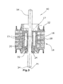
- FIG. 3 shows a longitudinal section of the electric drive motor 40 of the motor vehicle unit 10 in the assembled final state.
- the motor rotor 16 with its permanent magnets 23 is axially completely brought into axial overlap with the motor stator 18.
- the motor rotor shaft 14 is threaded through the joining aid 30, ie through the shaft opening 24 provided with a chamfer 24, into the motor stator 18, and sits now free of play rotatable in the shaft opening.
Landscapes
- Engineering & Computer Science (AREA)
- Power Engineering (AREA)
- Chemical & Material Sciences (AREA)
- Combustion & Propulsion (AREA)
- Mechanical Engineering (AREA)
- General Engineering & Computer Science (AREA)
- Manufacturing & Machinery (AREA)
- Iron Core Of Rotating Electric Machines (AREA)
Abstract
Description
- Die Erfindung betrifft ein elektrisches Kfz-Aggregat mit einem elektronisch kommutierten Antriebsmotor, der einen permanentmagnetischen Motorrotor mit einer Motorrotorwelle, einen Motorstator und ein Motorgehäuse aufweist.
- Ein elektrisch angetriebenes Kfz-Aggregat kann vorliegend eine quasikontinuierlich fördernde Pumpe sein, beispielsweise eine Kühlmittel- oder eine Schmiermittelpumpe - kann aber auch als Steller ausgebildet sein, beispielsweise als Drosselklappensteller. Der Motorrotor des elektronisch kommutierten Antriebsmotors weist zur Erzeugung eines elektrischen Feldes mindestens einen Permanentmagneten auf.
- Der Motorrotor sitzt auf der Motorrotorwelle und weist einen aus Vollmaterial gefertigten ferromagnetischen Rotorgrundkörper auf, der in axialer Richtung auf die Motorrotorwelle aufgeschoben ist, und der gegebenenfalls Aussparungen zur Aufnahme der Permanentmagnete aufweist.
- Derartige Permanentmagnete der Rotorgrundkörper und/oder der Motorstator können empfindlich sein, so dass bei der Montage, d.h. beim Fügen der Motorrotorwelle in den Motorstator, darauf geachtet werden muss, dass ein Verkratzen bzw. eine Beschädigung der Oberflächen und/ oder der Beschichtung vermieden wird. Dies wird während der Montage dadurch erschwert, dass der Motorrotor durch die radial wirkenden Magnetkräfte radial in eine Richtung gezogen wird, sobald der Motorrotor in den magnetischen Wirkbereich des Motorstators gerät.
- Daher ist es die Aufgabe der vorliegenden Erfindung, ein elektrisches Kfz-Aggregat für eine einfache und sichere Montage zu schaffen.
- Die Lösung der Aufgabe erfolgt erfindungsgemäß durch ein Kfz-Aggregat mit den Merkmalen des Anspruchs 1.
- Beim Zusammenbau des elektronisch kommutierten Antriebsmotors wird das vorauseilende Wellenende der Motorrotorwelle in eine feststehende Wellenöffnung eingefädelt. Die Motorrotorwelle ist längenmäßig derart ausgebildet, dass das beim Zusammenbau vorauseilende Wellenende der Motorrotorwelle schon in Eingriff mit der Wellenöffnung kommt, bevor der permanentmagnetische Motorrotor in den magnetischen Wirkbereich des Motorstators gerät.
- Während des Fügens des Motorrotors in den Motorstator sind auf diese Weise störende radial wirkende Magnetkräfte praktisch vollständig ausgeschlossen. Erst nach der Einfügung des vorauseilenden Wellenendes der Motorrotorwelle in die Wellenöffnung wirken die radialen Magnetkräfte zwischen dem Motorrotor und dem Motorstator. Durch diese Maßnahme ist die Motorrotorwelle bereits an ihrem einem Längsende abgestützt, bevor die radialen Magnetkräfte erheblich zu wirken beginnen. Das noch freie nacheilende Wellenende der Motorrotorwelle wird manuell abgestützt, so dass verhindert wird, dass der Motorstator und der Motorrotor während der Montage radial zueinander gezogen werden und zusammenstoßen. Hierdurch wird die bei der Montage bestehende Gefahr einer Beschädigung erheblich verringert.
- Der magnetische Wirkbereich des Motorstators wird im Sinne des Hauptanspruches 1 durch den Motorrotor nicht erreicht, solange die radialen Magnetkräfte zwischen Motorrotor und Motorstator weniger als die Hälfte, bevorzugt weniger als 30% und insbesondere bevorzugt weniger als 10% der radialen Magnetkräfte in der axialen Endposition des Motorrotors in dem Motorstator betragen.
- Gemäß einer bevorzugten Ausführungsform ist der Permanentmagnet nicht vollständig in den ferromagnetischen Rotorgrundkörper eingebettet. Der Permanentmagnet kann stattdessen von radial außen in eine entsprechende Ausnehmung des Rotorgrundkörpers eingesetzt und von außen "sichtbar" sein.
- Eine weitere bevorzugte Ausführungsform sieht vor, dass die Motorrotorwelle durch eine Fügehilfe während der axialen Fügebewegung zunächst zentriert und schließlich eingefädelt wird, bevor nennenswerte radiale Magnetkräfte auf den Motorrotor wirken. Mit dem Begriff "zentriert" ist vorliegend gemeint, dass die endzentrierte Radialposition des vorauseilenden Längsendes der Motorrotorwelle nicht exakt der Radialposition während der Zentrierung entsprechen muss. Durch die Vermeidung von radialen Magnetkräften während des Zentrierens wird die Montage, insbesondere die manuelle Montage, vereinfacht und somit die Gefahr möglicher Beschädigungen verringert.
- In einer bevorzugten Ausführung kommen das vorauseilende Wellenende der Motorrotorwelle und die Wellenöffnung miteinander in Eingriff, bevor sich der Motorrotor und die Statorpoleisen des Motorstators in Längsrichtung überlappen.
- Solange sich diese beiden Bauteile überhaupt nicht überlappen, sind die radialen Magnetkräfte sehr gering, beziehungsweise belaufen sich auf annähernd Null. Durch die sehr geringen Magnetkräfte besteht während des Montagevorganges keine größere Gefahr, dass der Motorrotor durch Magnetkräfte in eine radiale Richtung gezogen wird und radial an den Motorstator anschlägt.
- In einer weiteren bevorzugten Ausführung wird die Wellenöffnung durch einen Spulenträger gebildet, auf den die Motorspulen aufgewickelt sind. Der Spulenträger kann dabei beispielsweise ein - oder zweiteilig aufgebaut sein. Die Wellenöffnung kann durch eine separate Lagerbuchse, beispielsweise eine metallische Lagerbuchse realisiert sein, die in den Spulenträger eingesetzt bzw. eingespritzt ist. Die Statorpoleisen können ebenfalls in den Kunststoff-Spulenträger eingespritzt sein.
- In einer weiteren bevorzugten Ausführungsform der Erfindung kann der Spulenträger aus einem Kunststoff gefertigt sein, in welchen bevorzugt ferromagnetische Metallpartikel verteilt eingebettet sind. Die Metallpartikel können dabei aus einer ferromagnetischen Metalllegierung bestehen, um ferromagentische Verluste möglichst gering zu halten. Der ferromagnetische Spulenträger lässt sich beispielsweise durch Spritzgießverfahren bereitstellen. Zur Füllung des Kunststoffes eignet sich dabei insbesondere ein weichmagnetisches Material. Der Spulenträger bildet hierbei auch bevorzugt die Statorpoleisen.
- In einer weiteren bevorzugten Ausführungsform sind das vorauseilende Wellenende und/oder die Wellenöffnung derart zirkulär abgeschrägt, dass das Einfädeln des Motorrotors in den Motorstator erleichtert wird. Sowohl das vorauseilende Wellenende der Motorrotorwelle, als auch die Wellenöffnung des Spulenträgers weisen eine definierte Fase auf. Diese Fase vergrößert die Zielfläche, in welche das vorauseilende Wellenende der Motorrotorwelle zur Einfädelung auftreffen muss. Dadurch wird die Montage zusätzlich vereinfacht.
- In einer bevorzugten Ausführungsform ist das Kfz-Aggregat ein elektrisch betriebener Drosselklappenstutzen.
- Nachfolgend wird die Erfindung an Hand einer bevorzugten Ausführungsform unter Bezugnahme auf die anliegenden Zeichnungen näher erläutert.
- Es zeigen:
- Figur 1:
- einen Längsschnitt eines als Drosselklappenstutzen ausgebildeten Kfz-Aggregats mit einem elektronisch kommutierten Antriebsmotor;
- Figur 2:
- einen Längsschnitt des nicht-montierten elektrischen Antriebsmotors des Kfz-Aggregates aus
Figur 1 , und - Figur 3:
- einen Längsschnitt des montierten elektrischen Antriebsmotors des Kfz-Aggregates aus
Figur 1 . - Eine zum Antrieb eines Kraftfahrzeuges (Kfz) vorgesehene Kfz-Brennkraftmaschine weist zur Steuerung ihrer Leistungsabgabe einen Drosselklappenstutzen 42 auf. Der in
Figur 1 dargestellte Drosselklappenstutzen 42 sitzt in dem Kfz im Ansaugkanal der Brennkraftmaschine und dient der Einstellung der der Brennkraftmaschine zugeführten Luftmasse. - Der Drosselklappenstutzen weist eine Drosselklappe 46 auf, die beim Betrieb den Leitungsquerschnitt mehr oder weniger frei gibt bzw. verschließt. Der Drosselklappenstutzen 42 weist ferner ein Drosselklappenstutzen-Rohr 44 auf, in dem die Drosselklappe 46 angeordnet ist, die auf einer Drosselklappenwelle 48 sitzt. Die drehbar gelagerte Drosselklappenwelle 48 wird über ein Übersetzungsgetriebe 64 angetrieben. Das Untersetzungsgetriebe 64 wird über einen elektronisch kommutierten Antriebsmotor 40 angetrieben. Über die Drosselklappenwelle 48 ist die Drosselklappe 46 zwischen einer Öffnungsstellung und einer Schließstellung um die Drehachse um ca. 90°drehbar gelagert.
- Die Drosselklappenwelle 48 ist über das Untersetzungsgetriebe 64 mit einer Motorrotorwelle 14 mechanisch gekoppelt. Auf der Motorrotorwelle 14 sitzt ein permanentmagentischer Motorrotor 16. Der permanentmagnetische Motorrotor 16 ist umgeben von einem Motorstator 18. Das Untersetzungsgetriebe 64, der permanentmagnetische Motorrotor 16, der Motorstator 18 und die Motorrotorwelle 14 sind von einem Motorgehäuse 50 umgeben.
- Die
Figur 2 zeigt einen Längsschnitt des Motorrotors 16 und des Motorrotors 18 des elektrischen Antriebsmotors 40 im nicht-montierten Zustand. Der Motorrotor 16 weist einen Rotorgrundkörper 17 auf, in den mehrere Permanentmagnete 23 eingelassen sind, die mehrere magnetische Rotorpole bilden. Der Motorrotor 16 ist drehfest auf der Motorrotorwelle 14 fixiert. - Das elektrische Kfz-Aggregat 10 weist ferner einen Motorstator 18 auf. Der Motorstator 18 weist mehrere Statorspulen 22 auf, die mit den magentischen Polen des Motorrotors 16 in magnetischer Wechselwirkung stehen. Der Motorstator 18 weist ferner einen Kunststoff-Spulenträger auf, auf den die Statorspulen 22 aufgewickelt sind und in den mehrere Statorpoleisen eingegossen sind. Der Spulenträger 19 weist axial mittig eine Wellenöffnung 24 für das Einführen der Motorrotorwelle 14 in den Spulenträger 19 auf.
- Die Wellenöffnung 24 des Spulenträgers 19 weist proximal eine zirkuläre Fase 32 auf, so dass das Einführen des vorauseilenden Wellenendes 26 der Motorrotorwelle 14 in den Spulenträger 19 erleichtert wird. Auch das vorauseilende Wellenende 26 der Motorrotorwelle 14 weist eine korrespondierende zirkuläre Fase 34 auf und ist derart abgeschrägt, dass das Einfädeln des Motorrotors 16 in den Motorstator 18 erleichtert wird. Durch die Abschrägung des vorauseilenden Wellenendes 26 und/ oder der Wellenöffnung 24 wird die Zielfläche für das Einfädeln vergrößert. Erst nach dem Einstecken des vorauseilenden Wellenendes 26 der Motorrotorwelle 14 in die Wellenöffnung 24 wirken nennenswerte radiale Magnetkräfte zwischen dem Motorrotor 16 und dem Motorstator 18. Durch diese Vorrichtung wird die Motorrotorwelle 14 an einem Längsende bereits abgestützt, bevor die radialen Magnetkräfte zwischen dem permanentmagnetischen Motorrotor 16 und dem Motorstator 18 eine nennenswerte Größe erreichen.
- Die Motorrotorwelle 14 ist derart ausgebildet, dass im nicht-montierten Zustand das vorauseilende und abgeschrägte Wellenende 26 der Motorrotorwelle 14 in Eingriff mit der Wellenöffnung 24 kommt, bevor der permanentmagnetische Motorrotor 16 in den magnetischen Wirkbereich des Motorstators 18 gerät.
- Die
Figur 3 zeigt einen Längsschnitt des elektrischen Antriebsmotors 40 des Kfz-Aggregates 10 im montierten Endzustand. In diesem Endzustand ist der Motorrotor 16 mit seinen Permanentmagneten 23 axial vollständig in axiale Überdeckung gebracht mit dem Motorstator 18. Die Motorrotorwelle 14 ist durch die Fügehilfe 30, d.h. durch die mit einer Fase 32 versehene Wellenöffnung 24, in den Motorstator 18 eingefädelt, und sitzt nun spielfrei drehbar in der Wellenöffnung.
Claims (7)
- Elektrisches Kfz-Aggregat (10) mit einem elektronisch kommutierten Antriebsmotor (40), der einen permanentmagnetischen Motorrotor (16) mit einer Motorrotorwelle (14), einen Motorstator (18) und ein Motorgehäuse (50) aufweist,
wobei beim Zusammenbau des Antriebsmotors (40) das vorauseilende Wellenende (26) der Motorrotorwelle (14) in eine feststehende Wellenöffnung (24) eingefädelt wird,
dadurch gekennzeichnet, dass
die Motorrotorwelle (14) derart ausgebildet ist, dass beim Zusammenbau das vorauseilende Wellenende (26) der Motorrotorwelle (14) in Eingriff mit der Wellenöffnung (24) kommt, bevor der permanentmagnetische Motorrotor (16) in den magnetischen Wirkbereich des Motorstators (18) gerät. - Elektrisches Kfz-Aggregat (10) nach einem der vorangegangenen Ansprüche, wobei die Motorrotorwelle (14) durch eine Fügehilfe (30) zentriert und in Längsrichtung geführt wird, bevor in dem Wirkbereich radiale Magnetkräfte auf den Motorrotor (16) wirken.
- Elektrisches Kfz-Aggregat (10) nach einem der vorangegangenen Ansprüche, wobei das vorauseilende Wellenende (26) der Motorrotorwelle (14) und die Wellenöffnung (24) miteinander in Eingriff kommen, bevor
sich der Motorrotor (16) und Statorpoleisen (20) des Motorstators (18) in Längsrichtung überlappen. - Elektrisches Kfz-Aggregat (10) nach einem der vorangegangenen Ansprüche, wobei die Wellenöffnung (24) durch einen Spulenträger (19) gebildet wird, auf den eine Motorspule (22) des Motorstators (18) aufgewickelt ist.
- Elektrisches Kfz-Aggregat (10) nach einem der vorangegangenen Ansprüche, wobei der Spulenträger (19) aus einem Kunststoff-Spritzgussteil besteht.
- Elektrisches Kfz-Aggregat (10) nach einem der vorangegangenen Ansprüche, wobei die Fügehilfe (30) durch jeweils eine zirkuläre Fase (34, 32) an dem vorauseilenden Wellenende (26) der Motorrotorwelle (14) und/oder der Wellenöffnung (24) gebildet wird, so dass das Einfädeln erleichtert wird.
- Elektrisches Kfz-Aggregat (10) nach einem der vorangegangenen Ansprüche, wobei das Kfz-Aggregat (10) ein elektrisch betriebener Drosselklappenstutzen (42) ist.
Priority Applications (1)
| Application Number | Priority Date | Filing Date | Title |
|---|---|---|---|
| EP13166034.2A EP2800245A1 (de) | 2013-04-30 | 2013-04-30 | Elektrischer Antrieb eines KfZ-Aggregats |
Applications Claiming Priority (1)
| Application Number | Priority Date | Filing Date | Title |
|---|---|---|---|
| EP13166034.2A EP2800245A1 (de) | 2013-04-30 | 2013-04-30 | Elektrischer Antrieb eines KfZ-Aggregats |
Publications (1)
| Publication Number | Publication Date |
|---|---|
| EP2800245A1 true EP2800245A1 (de) | 2014-11-05 |
Family
ID=48288826
Family Applications (1)
| Application Number | Title | Priority Date | Filing Date |
|---|---|---|---|
| EP13166034.2A Withdrawn EP2800245A1 (de) | 2013-04-30 | 2013-04-30 | Elektrischer Antrieb eines KfZ-Aggregats |
Country Status (1)
| Country | Link |
|---|---|
| EP (1) | EP2800245A1 (de) |
Citations (4)
| Publication number | Priority date | Publication date | Assignee | Title |
|---|---|---|---|---|
| EP0769839A1 (de) * | 1995-10-20 | 1997-04-23 | Honda Giken Kogyo Kabushiki Kaisha | Motor mit Reduktionsgetriebe, Montageverfahren und Wartungsverfahren desselben |
| US6205644B1 (en) * | 1997-12-04 | 2001-03-27 | Emerson Electric Co. | Method of assembling an electric motor |
| WO2001043261A1 (en) * | 1999-12-10 | 2001-06-14 | Matsushita Electric Industrial Co. Ltd. | Motor assembled by using motor-base-holder and method of assembling the same motor |
| US6753628B1 (en) * | 1999-07-29 | 2004-06-22 | Encap Motor Corporation | High speed spindle motor for disc drive |
-
2013
- 2013-04-30 EP EP13166034.2A patent/EP2800245A1/de not_active Withdrawn
Patent Citations (4)
| Publication number | Priority date | Publication date | Assignee | Title |
|---|---|---|---|---|
| EP0769839A1 (de) * | 1995-10-20 | 1997-04-23 | Honda Giken Kogyo Kabushiki Kaisha | Motor mit Reduktionsgetriebe, Montageverfahren und Wartungsverfahren desselben |
| US6205644B1 (en) * | 1997-12-04 | 2001-03-27 | Emerson Electric Co. | Method of assembling an electric motor |
| US6753628B1 (en) * | 1999-07-29 | 2004-06-22 | Encap Motor Corporation | High speed spindle motor for disc drive |
| WO2001043261A1 (en) * | 1999-12-10 | 2001-06-14 | Matsushita Electric Industrial Co. Ltd. | Motor assembled by using motor-base-holder and method of assembling the same motor |
Similar Documents
| Publication | Publication Date | Title |
|---|---|---|
| DE102006000446B4 (de) | Fluidpumpe und Elektromotor und deren Herstellungsverfahren | |
| DE102009006355A1 (de) | Proportionalmagnet für ein hydraulisches Wegeventil und Verfahren zu dessen Herstellung | |
| DE102009027117B4 (de) | Elektrischer Antrieb sowie Verfahren zur Montage eben dieses Antriebs | |
| DE102019127583A1 (de) | Rotoreinrichtung und Verfahren zur Herstellung einer Rotoreinrichtung für eine elektrische Maschine, insbesondere für einen Fahrzeugantrieb für ein Elektrofahrzeug | |
| DE19710470A1 (de) | Antriebsschneckeneinheit sowie die Einheit verwendender Elektromotor | |
| DE102014100036A1 (de) | Arretierungsvorrichtung für Kühlgebläsebaugruppe | |
| DE102010023094A1 (de) | Can-Stack-Linearantrieb | |
| DE4038761A1 (de) | Drehsteller | |
| DE102011017534A1 (de) | Startvorrichtung für eine Brennkraftmaschine | |
| DE102009059116A1 (de) | Elektromotor | |
| WO2009144055A1 (de) | Verfahren zur herstellung eines statorgehäuses eines elektromotors | |
| DE102014108700A1 (de) | Zentralaktuator für einen Schwenkmotorversteller einer Nockenwelle | |
| DE102006017233B4 (de) | Rotoranordnung für eine elektrische Maschine und Klauenpolmotor | |
| DE202008017587U1 (de) | Rotor | |
| EP2800245A1 (de) | Elektrischer Antrieb eines KfZ-Aggregats | |
| EP2715165A1 (de) | Vorrichtung zur einstellung von axialspiel | |
| EP2375055B1 (de) | Abdeckring für Startvorrichtung | |
| WO2011101174A1 (de) | Elektromagnetischer aktor | |
| DE102005049988A1 (de) | Magnettopfanordnung, Elektromagnetaktuator und Verfahren zum Herstellen einer Magnettopfanordnung | |
| WO2013087209A1 (de) | Elektromotorischer brems-aktuator einer kraftfahrzeug-feststellbremse | |
| DE102007004254B4 (de) | Elektromagnetische Stellvorrichtung | |
| DE102012207798A1 (de) | Startvorrichtung für eine Brennkraftmaschine | |
| DE102011080477A1 (de) | Starter und Startrelais mit Verdrehsicherung sowie Verfahren zu dessen Herstellung | |
| DE102010062241A1 (de) | Verfahren und Vorrichtung zum Betreiben eines Starters eines Fahrzeugs | |
| AT250491B (de) | Dauermagnetischer Rotor für eine kleine elektrische Maschine |
Legal Events
| Date | Code | Title | Description |
|---|---|---|---|
| PUAI | Public reference made under article 153(3) epc to a published international application that has entered the european phase |
Free format text: ORIGINAL CODE: 0009012 |
|
| 17P | Request for examination filed |
Effective date: 20130430 |
|
| AK | Designated contracting states |
Kind code of ref document: A1 Designated state(s): AL AT BE BG CH CY CZ DE DK EE ES FI FR GB GR HR HU IE IS IT LI LT LU LV MC MK MT NL NO PL PT RO RS SE SI SK SM TR |
|
| AX | Request for extension of the european patent |
Extension state: BA ME |
|
| R17P | Request for examination filed (corrected) |
Effective date: 20150505 |
|
| RBV | Designated contracting states (corrected) |
Designated state(s): AL AT BE BG CH CY CZ DE DK EE ES FI FR GB GR HR HU IE IS IT LI LT LU LV MC MK MT NL NO PL PT RO RS SE SI SK SM TR |
|
| STAA | Information on the status of an ep patent application or granted ep patent |
Free format text: STATUS: EXAMINATION IS IN PROGRESS |
|
| 17Q | First examination report despatched |
Effective date: 20190104 |
|
| STAA | Information on the status of an ep patent application or granted ep patent |
Free format text: STATUS: THE APPLICATION IS DEEMED TO BE WITHDRAWN |
|
| 18D | Application deemed to be withdrawn |
Effective date: 20190716 |