EP2799892B1 - Dispositif de détection de claquage et procédé de détection associé - Google Patents
Dispositif de détection de claquage et procédé de détection associé Download PDFInfo
- Publication number
- EP2799892B1 EP2799892B1 EP11878581.5A EP11878581A EP2799892B1 EP 2799892 B1 EP2799892 B1 EP 2799892B1 EP 11878581 A EP11878581 A EP 11878581A EP 2799892 B1 EP2799892 B1 EP 2799892B1
- Authority
- EP
- European Patent Office
- Prior art keywords
- current
- fault
- circuit
- detecting
- sta
- Prior art date
- Legal status (The legal status is an assumption and is not a legal conclusion. Google has not performed a legal analysis and makes no representation as to the accuracy of the status listed.)
- Active
Links
- 238000001514 detection method Methods 0.000 title claims description 14
- 230000015556 catabolic process Effects 0.000 title 1
- 230000004931 aggregating effect Effects 0.000 claims description 37
- 238000000034 method Methods 0.000 claims description 12
- 238000003491 array Methods 0.000 description 24
- 238000010586 diagram Methods 0.000 description 8
- 238000012806 monitoring device Methods 0.000 description 6
- 239000003990 capacitor Substances 0.000 description 5
- 238000009499 grossing Methods 0.000 description 5
- 238000012544 monitoring process Methods 0.000 description 1
- 230000001360 synchronised effect Effects 0.000 description 1
Images

Classifications
-
- H—ELECTRICITY
- H01—ELECTRIC ELEMENTS
- H01L—SEMICONDUCTOR DEVICES NOT COVERED BY CLASS H10
- H01L31/00—Semiconductor devices sensitive to infrared radiation, light, electromagnetic radiation of shorter wavelength or corpuscular radiation and specially adapted either for the conversion of the energy of such radiation into electrical energy or for the control of electrical energy by such radiation; Processes or apparatus specially adapted for the manufacture or treatment thereof or of parts thereof; Details thereof
- H01L31/02—Details
- H01L31/02016—Circuit arrangements of general character for the devices
- H01L31/02019—Circuit arrangements of general character for the devices for devices characterised by at least one potential jump barrier or surface barrier
- H01L31/02021—Circuit arrangements of general character for the devices for devices characterised by at least one potential jump barrier or surface barrier for solar cells
-
- G—PHYSICS
- G01—MEASURING; TESTING
- G01R—MEASURING ELECTRIC VARIABLES; MEASURING MAGNETIC VARIABLES
- G01R31/00—Arrangements for testing electric properties; Arrangements for locating electric faults; Arrangements for electrical testing characterised by what is being tested not provided for elsewhere
- G01R31/50—Testing of electric apparatus, lines, cables or components for short-circuits, continuity, leakage current or incorrect line connections
- G01R31/52—Testing for short-circuits, leakage current or ground faults
-
- H—ELECTRICITY
- H02—GENERATION; CONVERSION OR DISTRIBUTION OF ELECTRIC POWER
- H02S—GENERATION OF ELECTRIC POWER BY CONVERSION OF INFRARED RADIATION, VISIBLE LIGHT OR ULTRAVIOLET LIGHT, e.g. USING PHOTOVOLTAIC [PV] MODULES
- H02S50/00—Monitoring or testing of PV systems, e.g. load balancing or fault identification
- H02S50/10—Testing of PV devices, e.g. of PV modules or single PV cells
-
- Y—GENERAL TAGGING OF NEW TECHNOLOGICAL DEVELOPMENTS; GENERAL TAGGING OF CROSS-SECTIONAL TECHNOLOGIES SPANNING OVER SEVERAL SECTIONS OF THE IPC; TECHNICAL SUBJECTS COVERED BY FORMER USPC CROSS-REFERENCE ART COLLECTIONS [XRACs] AND DIGESTS
- Y02—TECHNOLOGIES OR APPLICATIONS FOR MITIGATION OR ADAPTATION AGAINST CLIMATE CHANGE
- Y02E—REDUCTION OF GREENHOUSE GAS [GHG] EMISSIONS, RELATED TO ENERGY GENERATION, TRANSMISSION OR DISTRIBUTION
- Y02E10/00—Energy generation through renewable energy sources
- Y02E10/50—Photovoltaic [PV] energy
Definitions
- Embodiments described herein relate generally to a fault detecting apparatus for detecting a fault based on a current.
- An object of the invention is to provide a fault detecting apparatus capable of reducing the number of current sensors configured to detect a fault.
- a fault detecting apparatus for detecting a fault in an electric circuit comprising a plurality of connecting circuits and an aggregating circuit, the plurality of connecting circuits comprising positive electrode wires and negative electrode wires connected parallel to respectively connect a plurality of DC power supplies with an inverter, and the aggregating circuit being configured to aggregate the plurality of connecting circuits and to connect the aggregated connecting circuits with the inverter.
- the apparatus comprises a plurality of connecting circuit current detecting means for detecting currents flowing through the positive electrode wires or the negative electrode wires of all the connecting circuits except one connecting circuit, respectively; aggregating current detecting means for detecting a current flowing through the aggregating circuit; and fault detecting means for detecting a fault when at least one of the connecting circuit current detecting means detects that a current flows and the aggregating current detecting means detects that a current does not flow.
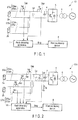
- FIG. 1 is a diagram showing a configuration of a photovoltaic system 10 to which a fault detecting apparatus 1 of First Embodiment is applied. Like or similar elements in the figure are denoted by similar reference numbers and their detailed descriptions are omitted, and different elements are mainly described. Duplicated descriptions are similarly omitted in the following embodiments, too.
- the photovoltaic system 10 in which two PV arrays 2a and 2b and two strings STa and STb are connected parallel is mainly described, but any number that is equal to or greater than two, of PV arrays and strings may be provided.
- the photovoltaic system 10 includes the fault detecting apparatus 1, two PV arrays 2a and 2b, two current sensors 3ap and 3sp, a smoothing capacitor 4, an inverter 5, and an interconnection transformer 6.
- the photovoltaic system 10 is connected to a power system 7.
- the strings STa and STb are circuits which connects the inverter 5 and the PV arrays 2a and 2b, respectively.
- the strings STa and STb include positive electrode wires STap and STbp and negative electrode wires STan and STbn, respectively.
- the positive electrode wires STap and STbp and the negative electrode wires STan and STbn, of the strings STa and STb, are connected to the PV arrays 2a and 2b, respectively.
- All the strings STa and STb are connected to a circuit including a set of wires Lp and Ln aggregated by parallel connection.
- the aggregated wires Lp and Ln are connected to a direct-current side of the inverter 5.
- Two PV arrays 2a and 2b are connected parallel to the direct-current side of the inverter 5.
- the PV arrays 2a and 2b are cells configured to generate power by light such as solar light.
- the PV arrays 2a and 2b supply the generated power to the inverter 5.
- the smoothing capacitor 4 is provided at the direct-current side of the inverter 5.
- the smoothing capacitor 4 smoothes DC voltages supplied from the PV arrays 2a and 2b.
- the inverter 5 converts the DC power supplied from the PV arrays 2a and 2b to an AC power synchronized with the power system 7.
- the inverter 5 supplies the converted AC power to the power system 7 via the interconnection transformer 6.
- the power system 7 is, for example, a commercial system.
- the inverter 5 may convert the DC power to a single-phase AC power or a three-phase AC power.
- the current sensor 3ap is provided to detect current Iap flowing through the positive electrode wire STap of the string STa.
- the current sensor 3ap outputs the detected current Iap to the fault detecting apparatus 1.
- the current sensor 3sp is provided to detect current Ip flowing through the aggregated positive electrode wire Lp.
- the current sensor 3sp outputs the detected current Ip to the fault detecting apparatus 1.
- the current sensor 3sp may serve as a current sensor provided at the direct-current side of the inverter 5 to enhance control accuracy.
- the current sensor 3ap is provided for two strings STa and STb to detect a fault. If the strings are n-parallel (where n is a natural number equal to or greater than 2), the current sensors are provided at positive electrodes or negative electrodes of all n-1 strings except one string. The number of the current sensors provided at the strings is therefore n-1. If the current sensor 3sp provided at the aggregated positive electrode wire Lp is added to these current sensors, the number of the current sensors employed in the fault detecting apparatus 1 is n.
- the fault detecting apparatus 1 detects the fault at each of the strings STa and STb, based on the currents Iap and Ip detected by two current sensors 3ap and 3sp. When the fault detecting apparatus 1 detects the fault, the fault detecting apparatus 1 outputs a fault detection signal Sng to notify occurrence of the fault to a host monitoring device 8.
- the fault detecting apparatus 1 determines that a fault current flows (i.e., a fault occurs). At this time, the direction of the detected current Iap is not considered.
- the strings are n-parallel, if the current is detected at at least one string, of all the strings at which the current sensors are provided and if the current Ip flowing through the aggregated positive electrode wire Lp is not detected, the fault current is determined to flow.
- the direction of the current flowing when all the PV arrays 2a and 2b normally generate the power is defined as a forward direction.
- the direction in which the currents Iap and Ip flowing through the positive electrode wires Lp, STap and STbp are input from the PV arrays 2a and 2b to the inverter 5 is the forward direction.
- the direction in which the currents flowing through the negative electrode wires Ln, STan and STbn are output from the inverter 5 to the PV arrays 2a and 2b, is the forward direction.
- the forward direction will also be hereinafter considered in this manner.
- the PV array 2b short-circuits at night and that the PV array 2a normally starts generating the power in the daytime.
- the current output from the PV array 2a flows to the PV array 2b.
- a circulating circuit flows between two strings STa and STb, no current flows in the aggregated wires Lp and Ln.
- the current Iap flows in the forward direction, in the positive electrode wire STap of the string STa and the current Ibp flows in the opposite direction, in the positive electrode wire STbp of the string STb.
- the PV array 2a short-circuits at night and that the PV array 2b normally starts generating the power in the daytime.
- the current output from the PV array 2b flows to the PV array 2a.
- a circulating circuit flows between two strings STa and STb, no current flows in the aggregated wires Lp and Ln.
- the current Iap flows in the opposite direction, in the positive electrode wire STap of the string STa and the current Ibp flows in the forward direction, in the positive electrode wire STbp of the string STb.
- the fault current can be determined to flow.
- a fault that the PV arrays 2a and 2b short-circuit at night, etc., which does not cause an overcurrent to flow can be detected based on the current Iap detected by the current sensor 3ap provided at each of all the n-1 strings except one string and the current Ip detected by the current sensor 3sp provided at the aggregated wire Lp.
- the current sensors 3ap and 3sp may be provided on the negative electrode wires Ln and STan.
- a fault can be detected if the current sensor is provided at each of all the n-1 strings except one string and if the single current sensor is provided for the aggregated wires Lp and Ln. Therefore, the number of the provided current sensors is n, for the n-parallel strings.
- the devices for example, A/D converter
- wiring lines accompanying the current sensors can also be reduced.
- FIG. 2 is a diagram showing a configuration of a photovoltaic system 10A to which a fault detecting apparatus 1A of Second Embodiment is applied.
- the photovoltaic system 10A in which two PV arrays 2a and 2b and two strings STa and STb are connected parallel will be mainly described, but any number that is equal to or greater than two, of PV arrays and strings may be provided.
- an aggregated negative electrode wire Ln in the photovoltaic system 10 of the First Embodiment shown in FIG. 1 is grounded, the current sensor 3sp in the photovoltaic system 10 is replaced with a current sensor 3sn, two current sensors 3an and 3bp are added, and the fault detecting apparatus 1 in the photovoltaic system 10 is replaced with the fault detecting apparatus 1A.
- the other portions are the same as those of the First Embodiment.
- the current sensor 3an is provided to detect current Ian flowing through a negative electrode wire STan of the string STa.
- the current sensor 3an outputs the detected current Ian to the fault detecting apparatus 1A.
- the current sensor 3bp is provided to detect current Ibp flowing through a positive electrode wire STbp of the string STb.
- the current sensor 3bp outputs the detected current Ibp to the fault detecting apparatus 1A.
- the current sensor 3sn is provided to detect current In flowing through the aggregated negative electrode wire Ln.
- the current sensor 3sn is provided at a negative electrode which is a ground electrode.
- the current sensor 3sn outputs the detected current In to the fault detecting apparatus 1A.
- the current sensor 3sn may serve as a current sensor provided at a direct-current side of an inverter 5 to enhance the control accuracy.
- the fault detecting apparatus 1A three current sensors 3ap, 3an and 3bp are provided for two strings STa and STb to detect a fault. If the strings are n-parallel, the current sensors are provided at positive electrodes and negative electrodes of all n-1 strings except one string, and the current sensor is provided at the positive electrode or the negative electrode of the excluded string. The number of the current sensors provided at the strings is thus 2n-1. If the current sensor 3sn provided on the aggregated negative electrode (ground electrode) wire Ln is added to the current sensors, the number of the current sensors used in the fault detecting apparatus 1A is 2n.
- the fault detecting apparatus 1A detects a fault at each of the strings STa and STb, based on the currents Iap, Ian, Ibp and In detected by four current sensors 3ap, 3an, 3bp and 3sn. If the fault detecting apparatus 1A detects the fault, the fault detecting apparatus 1A outputs a fault detection signal Sng to notify occurrence of the fault to a host monitoring device 8.
- the fault detecting apparatus 1A computes a ground fault current Ig by the following equation, based on the currents Iap and Ibp flowing at the positive electrode sides of the respective strings STa and STb, and the current In flowing through the aggregated negative electrode wire Ln.
- Ig Iap + Ibp ⁇ In
- the fault detecting apparatus 1A determines that the computed ground fault current Ig is not zero (for example, the ground fault current Ig is equal to or greater than a preset current value), the fault detecting apparatus 1A determines that the ground fault has occurred.
- the ground fault current Ig is computed by subtracting the current flowing through the aggregated wire from a sum of the currents flowing through the positive electrode wires (or negative electrode wires) of the respective strings.
- the fault detecting apparatus 1A determines whether the ground fault occurs at the string STa or not, the fault detecting apparatus 1A computes a difference between the current Iap flowing at the positive electrode side and the current Ian flowing at the negative electrode side. If the fault detecting apparatus 1A discriminates that the computed difference is not zero (for example, the difference is equal to or greater than a preset current value), the fault detecting apparatus 1A determines that the ground fault has occurred at the string STa. Similarly to this, the fault detecting apparatus 1A also determines whether the ground fault has occurred at the string STb or not, based on a difference between the current Ibp flowing at the positive electrode side of the string STb and the current Ibn flowing at the negative electrode side of the string STb.
- the fault detecting apparatus 1A specifies the string STa or STb at which the ground fault has occurred, the fault detecting apparatus 1A includes the specified string at which the ground fault (fault) has occurred in the fault detection signal Sng, as information, and outputs the signal to the host monitoring device 8.
- the ground fault at the PV array 2a or 2b can be detected based on the currents Iap and Ian detected by the current sensors 3ap and 3an provided on both the electrodes of all the n-1 strings except one string, the current Ibp detected by the current sensor 3bp provided on either electrode of the remaining string, and the current In detected by the current sensor 3sn provided on the wire Ln of the aggregated grounding electrode. If the strings are n-parallel, the number of the provided current sensors is 2n. In FIG. 2 , the negative electrode side is the grounding electrode and the current sensor 3sn is used for the detection, but the current sensor 3sp is arranged instead of the current sensor 3sn to execute the detection in the configuration in which the positive electrode side is grounded.
- the number of the current sensors can be reduced by allowing the current sensor 3sp provided on the aggregated wire Lp to serve as the current sensor to be used for the control of the inverter 5.
- the devices for example, A/D converter
- wiring lines accompanying the current sensors can be thereby reduced.
- the fault detecting apparatus 1A can measure the ground fault current Ig. Therefore, a current sensor configured to measure the ground fault current does not need to be provided on the ground line, etc. By measuring the ground fault current Ig, the fault detecting apparatus 1A can also allow a signal which stops the inverter 5 (gate block, etc.) to be output if, for example, the ground fault current is equal to or higher than a predetermined current value.
- FIG. 3 is a diagram showing a configuration of a photovoltaic system 10B to which a fault detecting apparatus 1B of Third Embodiment is applied.
- the photovoltaic system 10B in which two strings STc and STd are connected parallel to a PV array 2 will be mainly described, but any number that is equal to or greater than two, of strings may be connected parallel to the single PV array.
- the photovoltaic system 10B comprises the fault detecting apparatus 1B, the PV array 2, three current sensors 3cp, 3cn and 3sp, a smoothing capacitor 4, an inverter 5, an interconnection transformer 6, and four circuit breakers 9cp, 9cn, 9dp and 9dn.
- the photovoltaic system 10B is connected to a power system 7.
- the smoothing capacitor 4, the inverter 5, the interconnection transformer 6 and the power system 7 are configured similarly to those of the First Embodiment.
- the PV array 2 is configured similarly to the PV arrays 2a and 2b of the First Embodiment.
- the strings STc and STd are circuits which make connection between the PV array 2 and the inverter 5.
- the strings STc and STd include positive electrode wires STcp and STdp and negative electrode wires STcn and STdn, respectively.
- the positive electrode wires STcp and STdp and the negative electrode wires STcn and STdn, of the respective strings STc and STd, are connected to the PV array 2.
- All the strings STc and STd are connected to a set of wires Lp and Ln aggregated by parallel connection.
- the aggregated wires Lp and Ln are connected to a direct-current side of the inverter 5.
- Every two of four circuit breakers 9cp, 9cn, 9dp and 9dn are provided on the positive electrode wires STcp and STdp and the negative electrode wires STcn and STdn that make connection between the PV array 2 and the inverter 5.
- the capacities of the circuit breakers 9cp, 9cn, 9dp and 9dn can be made smaller and a circuit configuration equivalent to the circuit configuration provided with circuit breakers having a substantially large capacity can be obtained.
- the configuration using the circuit breakers will be described here, but the other devices may be used.
- the reason for dividing the current path into a plurality of paths may be to reduce the capacity of a fuse.
- various devices are often provided, depending on an aspect of the photovoltaic system 10B. The configuration may be therefore implemented for the purpose of reducing the capacities of these devices.
- the circuit breaker 9cp is provided on the positive electrode wire STcp of the string STc.
- the circuit breaker 9cn is provided on the negative electrode wire STcn of the string STc.
- the circuit breaker 9dp is provided on the positive electrode wire STdp of the string STd.
- the circuit breaker 9dn is provided on the negative electrode wire STdn of the string STd.
- the circuit breakers 9cp, 9cn, 9dp and 9dn disconnect and connect the wires STcp, STcn, STdp, and STdn in which the circuit breakers are provided, respectively.
- the current sensor 3cp is provided to detect the current Icp flowing through the positive electrode wire STcp of the string STc.
- the current sensor 3cp outputs the detected current Icp to the fault detecting apparatus 1B.
- the current sensor 3cn is provided to detect the current Icn flowing through the negative electrode wire STcn of the string STc.
- the current sensor 3cn outputs the detected current Icn to the fault detecting apparatus 1B.
- the current sensor 3sp is provided on the aggregated positive electrode wire Lp, similarly to the First Embodiment, but may be provided on the negative electrode wire Ln.
- two current sensors 3cp and 3cn are provided for the string STc, of two strings STc and STd, to detect a fault. If the strings are n-parallel, the current sensors are provided at positive electrodes and negative electrodes of all n-1 strings except one string. The number of the current sensors provided at the strings is thus 2(n-1). If the current sensor 3sp provided on the aggregated positive electrode wire Lp is added to these current sensors, the number of the current sensors used in the fault detecting apparatus 1B is 2n-1.
- the fault detecting apparatus 1B detects the fault at each of the strings STc and STd, based on the currents Icp, Icn and Ip detected by three current sensors 3cp, 3cn and 3sp. If the fault detecting apparatus 1B detects the fault, the fault detecting apparatus 1B outputs a fault detection signal Sng to notify occurrence of the fault to a host monitoring device 8.
- the fault detecting apparatus 1B computes the currents Idp and Idn flowing through the string STd at which no current sensor is provided, in the following equations, based on the currents Icp and Icn flowing through the string STc at which the current sensors 3cp and 3cn are provided and the current Ip flowing through the aggregated positive electrode wire Lp.
- the current flowing through the positive electrode wire of the string at which no current sensor is provided is computed by subtracting a sum of the currents flowing through the positive electrode wires of all the strings except the string at which no current sensor is provided, from the current flowing through the aggregated positive or negative electrode wire.
- the current flowing through the negative electrode wire of the string at which no current sensor is provided is computed by subtracting a sum of the currents flowing through the negative electrode wires of all the strings except the string at which no current sensor is provided, from the current flowing through the aggregated positive or negative electrode wire.
- the fault detecting apparatus 1B determines whether an unbalance current flows to two strings STc and STd or not.
- the fault detecting apparatus 1B compares the currents Icp and Idp flowing through the positive electrodes of two strings STc and STd. If the fault detecting apparatus 1B determines that the current amounts differs (for example, if the difference between two currents Icp and Idp is equal to or greater than a preset current value) as a result of comparing two currents Icp and Idp, the fault detecting apparatus 1B determines that an unbalance current flows. Similarly, the fault detecting apparatus 1B compares the currents Icn and Idn flowing through the negative electrodes of two strings STc and STd, and determines whether an unbalance current flows or not. At the comparison between the currents of two strings STc and STd, currents different in polarity may be compared.
- the fault detecting apparatus 1B determines whether a string at which a smaller amount of current (or a greater amount of current) flows is present or not, as compared with a current flowing through the other string. If a string at which such a current flows is present, the fault detecting apparatus 1B determines an unbalance current flowing.
- Two strings STc and STd are circuits connected parallel between the common single PV array 2 and the direct-current side of the inverter 5. No load is connected to two strings STc and STd.
- the circuit breakers 9cp, 9cn, 9dp and 9dn are provided at the positive and negative electrode wires STcp, STcn, STdp, and STdn of two strings STc and STd, respectively.
- An impedance of each of the circuit breakers 9cp, 9cn, 9dp and 9dn is ideally zero if they are closed.
- the impedance of two strings STc and STd is substantially zero.
- the currents flowing through two strings STc and STd should be, theoretically, substantially the same as each other.
- a fault that the impedance increases or the like is considered to occur at least one of the wires STcp, STcn, STdp, and STdn of the strings STc and STd.
- Reasons for occurrence of the fault are considered to be looseness of bolts which connect the devices such as the circuit breakers 9cp, 9cn, 9dp and 9dn, fault at the devices such as the circuit breakers 9cp, 9cn, 9dp and 9dn, etc. besides the ground fault.
- the fault detecting apparatus 1B can therefore detect the fault by detecting the flow of the unbalance current.
- the looseness of the bolts, the fault at the circuit breakers 9cp, 9cn, 9dp and 9dn, etc. can be detected, based on the currents Icp and Icn detected by the current sensors 3cp and 3cn each provided at both the electrodes of all the n-1 strings except one string, and the current Ip detected by the current sensor 3sp provided at the aggregated wire Lp.
- the number of the provided current sensors is thus 2n-1, at the n-parallel strings.
- the number of the current sensors can be further reduced.
- the devices for example, A/D converter
- wiring lines accompanying the current sensors can also be reduced.
- FIG. 4 is a diagram showing a configuration of a photovoltaic system 10C to which a fault detecting apparatus 1C of Fourth Embodiment is applied.
- the photovoltaic system 10C in which two PV arrays 2a and 2b and two strings STa and STb are connected parallel will be mainly described, but any number that is equal to or greater than two, of PV arrays and strings may be provided.
- the current sensor 3sp in the photovoltaic system 10 of the First Embodiment shown in FIG. 1 is replaced with the current sensor 3bp of the Second Embodiment, and the fault detecting apparatus 1 in the photovoltaic system 10 is replaced with the fault detecting apparatus 1C.
- the other portions are the same as those of the First Embodiment.
- single current sensor 3ap or 3bp is provided for each of two strings STa and STb to detect a fault. If the strings are n-parallel, the current sensors are provided at either positive electrodes or negative electrodes of all the strings. The number of the current sensors used in the fault detecting apparatus 1C is n.
- the fault detecting apparatus 1C detects the fault at each of the strings STa and STb, based on the currents Iap and Ibp detected by two current sensors 3ap and 3bp. When the fault detecting apparatus 1C detects the fault, the fault detecting apparatus 1C outputs a fault detection signal Sng to notify occurrence of the fault to a host monitoring device 8.
- the fault detecting apparatus 1C determines directions of the currents Iap and Ibp flowing through the positive electrode side of all the strings STa and STb. If the fault detecting apparatus 1C determines that at least one of the directions of the currents Iap and Ibp flowing through the strings STa and STb is an opposite direction, the fault detecting apparatus 1C determines that the fault occurs at the strings STa and STb.
- the current Ibp flowing through the string STb flows in an opposite direction, as described in the First Embodiment.
- the current Iap flowing through the string STa flows in an opposite direction.
- the fault that the PV arrays 2a and 2b short-circuit at night, which causes an overcurrent not to flow can be detected, based on the currents Iap and Ibp detected by the current sensors 3ap and 3bp each provided at each of all the strings.
- the current sensors 3ap and 3bp may be provided at the negative electrode wires STan and STbn. In other words, if the current sensor is provided at each of all the strings, the fault can be detected. Thus, the number of the provided current sensors is n, for the n-parallel strings.
- the devices for example, A/D converter
- wiring lines accompanying the current sensors can be reduced.
- the fault detecting apparatuses 1-1C are provided outside the inverter 5, but may be implemented as a function of the inverter 5.
- the fault detecting apparatuses 1-1C are configured to output the fault detection signal Sng to the host monitoring device 8 if the fault is detected, but are not limited to this configuration.
- the fault detecting apparatuses 1-1C may output the fault detection signal Sng to the inverter 5 or may output the fault detection signal Sng to the other device.
- the fault detecting apparatuses 1-1C may output a signal for opening to the circuit breakers to protect the system, or may output the other protecting operation or an alarm, instead of the fault detection signal Sng.
- each of the embodiments is configured to use the PV arrays 2, 2a or 2b, but may use the other power generator or a power supply such as a battery.
- the invention can provide a fault detecting apparatus capable of reducing the number of current sensors configured to detect a fault.
Landscapes
- Engineering & Computer Science (AREA)
- Physics & Mathematics (AREA)
- General Physics & Mathematics (AREA)
- Electromagnetism (AREA)
- Sustainable Energy (AREA)
- Condensed Matter Physics & Semiconductors (AREA)
- Life Sciences & Earth Sciences (AREA)
- Sustainable Development (AREA)
- Computer Hardware Design (AREA)
- Microelectronics & Electronic Packaging (AREA)
- Power Engineering (AREA)
- Testing Of Short-Circuits, Discontinuities, Leakage, Or Incorrect Line Connections (AREA)
- Inverter Devices (AREA)
- Emergency Protection Circuit Devices (AREA)
- Photovoltaic Devices (AREA)
Claims (10)
- Appareil de détection de défaut (1) destiné à détecter un défaut dans un circuit électrique comprenant une pluralité de circuits de connexion (STa, STb) et un circuit de agrégation (Lp, Ln), la pluralité de circuits de connexion (STa, STb) comprenant des fils électrodes positifs (STap, STbp) et des fils électrodes négatifs (STan, STbn) connectés en parallèle pour connecter respectivement une pluralité d'alimentations électriques CC (2a, 2b) à un inverseur (5), et le circuit de agrégation (Lp, Ln) étant configuré pour agréger la pluralité de circuits de connexion (STa, STb) et pour connecter les circuits de connexion (STa, STb) agrégés à l'inverseur (5), l'appareil (1) étant caractérisé en ce qu'il comprend :une pluralité de moyens de détection de courant de circuit de connexion (3ap) destinés à détecter des courants (Iap) circulant par les fils électrodes positifs (STap) ou les fils électrodes négatifs (STan) de tous les circuits de connexion (STa) à l'exception d'un circuit de connexion (STb), respectivement ;des moyens de détection de courant de agrégation (3sp) destinés à détecter un courant (Ip) circulant par le circuit de agrégation (Lp, Ln) ; etdes moyens de détection de défaut destinés à détecter un défaut lorsqu'au moins un des moyens de détection de courant de circuit de connexion (3ap) détecte qu'un courant (Iap) circule et les moyens de détection de courant de agrégation (3sp) détectent qu'un courant (Ip) ne circule pas.
- Appareil de détection de défaut (1A) destiné à détecter un défaut dans un circuit électrique comprenant une pluralité de circuits de connexion (STa, STb) et un circuit de agrégation (Lp, Ln), la pluralité de circuits de connexion (STa, STb) comprenant des fils électrodes positifs (STap, STbp) et des fils électrodes négatifs (STan, STbn) connectés en parallèle afin de connecter respectivement une pluralité d'alimentations électriques CC (2a, 2b) à un inverseur (5), et le circuit de agrégation (Lp, Ln) étant configuré pour agréger la pluralité de circuits de connexion (STa, STb) et pour connecter les circuits de connexion (STa, STb) agrégés à l'inverseur (5), l'appareil (1A) étant caractérisé en ce qu'il comprend :une pluralité de moyens de détection de courant de circuit de connexion (3ap, 3an, 3bp) destinés à détecter des courants (Iap, Ian, Ibp) circulant par le fil électrode positif (STbp) ou le fil électrode négatif (STbn) d'un des circuits de connexion (STb), et les fils électrodes positifs (STap) ou les fils électrodes négatifs (STan) de tous les circuits de connexion (STa) restants, respectivement ;des moyens de détection de courant de agrégation (3sn) destinés à détecter un courant (In) circulant par un fil électrode de mise à la terre (Ln) du circuit de agrégation (Lp, Ln) ;des moyens de calcul de courant de défaut de terre destinés à calculer un courant de défaut de terre, sur la base des courants (Iap, Ian, Ibp) détectés par la pluralité de moyens de détection de courant de circuit de connexion (3ap, 3an, 3bp), respectivement, et du courant (In) détecté par les moyens de détection de courant de agrégation (3sn) ; etdes moyens de détection de défaut destinés à détecter un défaut de terre comme défaut, sur la base du courant de défaut de terre calculé par les moyens de calcul de courant de défaut de terre.
- L'appareil de détection de défaut (1A) de la revendication 2, caractérisé en ce qu'il comprend en outre :
des moyens de spécification de défaut destinés à spécifier le circuit de connexion défectueux, sur la base des courants (Iap, Ian, Ibp) détectés par la pluralité de moyens de détection de courant de circuit de connexion (3ap, 3an, 3bp), respectivement, et du courant (In) détecté par les moyens de détection de courant de agrégation (3sn), lorsque le défaut est détecté par les moyens de détection de défaut. - Appareil de détection de défaut (1B) destiné à détecter un défaut dans un circuit électrique comprenant une pluralité de circuits de connexion (STc, STd) et un circuit de agrégation (Lp, Ln), la pluralité de circuits de connexion (STc, STd) comprenant des fils électrodes positifs (STcp, STdp) et des fils électrodes négatifs (STcn, STdn) connectés en parallèle pour connecter une alimentation électrique CC (2) à un inverseur (5), et le circuit de agrégation (Lp, Ln) étant configuré pour agréger la pluralité de circuits de connexion (STc, STd) et pour connecter les circuits de connexion (STc, STd) agrégés à l'inverseur (5), l'appareil (1B) étant caractérisé en ce qu'il comprend :une pluralité de moyens de détection de courant de circuit de connexion (3sp) destinés à détecter des courants (Icp, Icn) circulant par les fils électrodes positifs (STcp) ou les fils électrodes négatifs (STcn) de tous les circuits de connexion (STc) à l'exception d'un circuit de connexion (STd), respectivement ;des moyens de détection de courant de agrégation (3sp) destinés à détecter un courant (Ip) circulant par le circuit de agrégation (Lp, Ln) ;des moyens de calcul de courant de circuit de connexion destinés à calculer des courants (Idp, Idn) circulant par le fil électrode positif (STdp) et le fil électrode négatif (STdn), respectivement, du circuit de connexion (STd) au niveau duquel les moyens de détection de courant de circuit de connexion ne sont pas prévus, sur la base des courants (Icp, Icn) détectés par la pluralité de moyens de détection de courant de circuit de connexion (3cp, 3cn), respectivement, et du courant (Ip) détecté par les moyens de détection de courant de agrégation (3sp) ;des moyens de comparaison de courant destinés à comparer les courants (Icp, Icn, Idp, Idn) circulant par la pluralité de circuits de connexion (STc, STd), sur la base des courants détectés par la pluralité de moyens de détection de courant de circuit de connexion (3cp, 3cn), respectivement, et de chacun des courants (Idp, Idn) calculés par les moyens de calcul de courant de circuit de connexion ; etdes moyens de détection de défaut destinés à détecter un défaut lorsqu'il est détecté qu'un courant de déséquilibre circule comme résultat de la comparaison effectuée par les moyens de comparaison de courant.
- Appareil de détection de défaut (1C) destiné à détecter un défaut dans un circuit électrique comprenant une pluralité de circuits de connexion (STa, STb) et un circuit de agrégation (Lp, Ln), la pluralité de circuits de connexion (STa, STb) comprenant des fils électrodes positifs (STap, STbp) et des fils électrodes négatifs (STan, STbn) connectés en parallèle pour connecter respectivement une pluralité d'alimentations électriques CC (2a, 2b) à un inverseur (5), et le circuit de agrégation (Lp, Ln) étant configuré pour agréger la pluralité de circuits de connexion (STa, STb) et pour connecter les circuits de connexion (STa, STb) agrégés à l'inverseur (5), l'appareil (1C) étant caractérisé en ce qu'il comprend :une pluralité de moyens de détection de courant de circuit de connexion (3ap, 3bp) destinés à détecter des courants (Iap, Ibp) circulant par les fils électrodes positifs (STap, STbp) ou les fils électrodes négatifs (STan, STbn) de tous les circuits de connexion (STa, STb), respectivement ; etdes moyens de détection de défaut destinés à détecter un défaut lorsqu'une direction d'un courant (Iap, Ibp) détecté par au moins un de la pluralité de moyens de détection de courant de circuit de connexion (3ap, 3bp) est opposée à des directions d'électricité fournie à l'inverseur (5) depuis les alimentations électriques CC (2a, 2b).
- Inverseur (5) caractérisé en ce qu'il comprend l'appareil de détection de défaut (1, 1A, 1B, 1C) de l'une quelconque des revendications 1 à 5.
- Procédé de détection de défaut destiné à détecter un défaut dans un circuit électrique comprenant une pluralité de circuits de connexion (STa, STb) et un circuit de agrégation (Lp, Ln), la pluralité de circuits de connexion (STa, STb) comprenant des fils électrodes positifs (STap, STbp) et des fils électrodes négatifs (STan, STbn) connectés en parallèle pour connecter respectivement une pluralité d'alimentations électriques CC (2a, 2b) à un inverseur (5), et le circuit de agrégation (Lp, Ln) étant configuré pour agréger la pluralité de circuits de connexion (STa, STb) et pour connecter les circuits de connexion (STa, STb) agrégés à l'inverseur (5), le procédé étant caractérisé en ce qu'il comprend :la détection de courants circulant par les fils électrodes positifs (STap) ou les fils électrodes négatifs (STan) de tous les circuits de connexion (STa) à l'exception d'un circuit de connexion (STb), respectivement ;la détection d'un courant (Ip) circulant par le circuit de agrégation (Lp, Ln) ; etla détection d'un défaut lorsqu'il est détecté qu'un courant (Iap) circule vers au moins un des circuits de connexion (STa) et qu'un courant (Ip) ne circule pas vers le circuit de agrégation (Lp, Ln).
- Procédé de détection de défaut destiné à détecter un défaut dans un circuit électrique comprenant une pluralité de circuits de connexion (STa, STb) et un circuit de agrégation (Lp, Ln), la pluralité de circuits de connexion (STa, STb) comprenant des fils électrodes positifs (STap, STbp) et des fils électrodes négatifs (STan, STbn) connectés en parallèle pour connecter respectivement une pluralité d'alimentations électriques CC (2a, 2b) à un inverseur (5), et le circuit de agrégation (Lp, Ln) étant configuré pour agréger la pluralité de circuits de connexion (STa, STb) et pour connecter les circuits de connexion (STa, STb) agrégés à l'inverseur (5), le procédé étant caractérisé en ce qu'il comprend :la détection de courants (Iap, Ian, Ibp) circulant par le fil électrode positif (STbp) ou le fil électrode négatif (STbn) d'un des circuits de connexion (STb), et les fils électrodes positifs (STap) et les fils électrodes négatifs (STan) de tous les circuits de connexion (STa) restants, respectivement ;la détection d'un courant (In) circulant par un fil électrode de mise à la terre (Ln) du circuit de agrégation (Lp, Ln) ;le calcul d'un courant de défaut de terre, sur la base des courants (Iap, Ian, Ibp) détectés circulant par les circuits de connexion (STa, STb), et du courant (In) détecté circulant par le circuit de agrégation (Lp, Ln) ; etla détection d'un défaut de terre comme défaut, sur la base du courant de défaut de terre calculé.
- Procédé de détection de défaut destiné à détecter un défaut dans un circuit électrique comprenant une pluralité de circuits de connexion (STc, STd) et un circuit de agrégation (Lp, Ln), la pluralité de circuits de connexion (STc, STd) comprenant des fils électrodes positifs (STcp, STdp) et des fils électrodes négatifs (STcn, STdn) connectés en parallèle pour connecter une alimentation électrique CC (2) à un inverseur (5), et le circuit de agrégation (Lp, Ln) étant configuré pour agréger la pluralité de circuits de connexion (STc, STd) et pour connecter les circuits de connexion (STc, STd) agrégés à l'inverseur (5), le procédé étant caractérisé en ce qu'il comprend :la détection de courants (Icp, Icn) circulant par les fils électrodes positifs (STcp) et les fils électrodes négatifs (STcn) de tous les circuits de connexion (STc) à l'exception d'un circuit de connexion (STd), respectivement ;la détection d'un courant (Ip) circulant par le circuit de agrégation (Lp, Ln) ;le calcul de courants (Idp, Idn) circulant par le fil électrode positif (STdp) et le fil électrode négatif (STdn), respectivement, du circuit de connexion (STd) qui n'effectue pas la détection, sur la base des courants (Icp, Icn) détectés circulant par la pluralité de circuits de connexion (STc), respectivement, et du courant (Ip) détecté circulant par le circuit de agrégation (Lp, Ln) ;la comparaison de courants (Icp, Icn, Idp, Idn) circulant par la pluralité de circuits de connexion (STc, STd), sur la base des courants (Icp, Icn) détectés circulant par la pluralité de circuits de connexion (STc), respectivement, et des courants (Idp, Idn) calculés circulant par les circuits de connexion (STd), respectivement ; etla détection d'un défaut lorsqu'il est détecté qu'un courant de déséquilibre circule comme résultat de la comparaison.
- Procédé de détection de défaut destiné à détecter un défaut dans un circuit électrique comprenant une pluralité de circuits de connexion (STa, STb) et un circuit de agrégation (Lp, Ln), la pluralité de circuits de connexion (STa, STb) comprenant des fils électrodes positifs (STap, STbp) et des fils électrodes négatifs (STan, STan) connectés en parallèle afin de connecter respectivement une pluralité d'alimentations électriques CC (2a, 2b) à un inverseur (5), et le circuit de agrégation (Lp, Ln) étant configuré pour agréger la pluralité de circuits de connexion (STa, STb) et pour connecter les circuits de connexion (STa, STb) agrégés à l'inverseur (5), le procédé étant caractérisé en ce qu'il comprend :la détection de courants (Iap, Ibp) circulant par les fils électrodes positifs (STap, STbp) ou les fils électrodes négatifs (STan, STbn) de tous les circuits de connexion (STa, STb), respectivement ; etla détection d'un défaut lorsqu'une direction du courant (Iap, Ibp) détecté circulant par au moins un des circuits de connexion (STa, STb) est opposée à des directions d'électricité fournie à l'inverseur (5) depuis les alimentations électriques CC (2a, 2b).
Applications Claiming Priority (1)
| Application Number | Priority Date | Filing Date | Title |
|---|---|---|---|
| PCT/JP2011/080072 WO2013098916A1 (fr) | 2011-12-26 | 2011-12-26 | Dispositif de détection de claquage et procédé de détection associé |
Publications (3)
| Publication Number | Publication Date |
|---|---|
| EP2799892A1 EP2799892A1 (fr) | 2014-11-05 |
| EP2799892A4 EP2799892A4 (fr) | 2015-07-08 |
| EP2799892B1 true EP2799892B1 (fr) | 2018-07-11 |
Family
ID=48696486
Family Applications (1)
| Application Number | Title | Priority Date | Filing Date |
|---|---|---|---|
| EP11878581.5A Active EP2799892B1 (fr) | 2011-12-26 | 2011-12-26 | Dispositif de détection de claquage et procédé de détection associé |
Country Status (6)
| Country | Link |
|---|---|
| US (1) | US9863992B2 (fr) |
| EP (1) | EP2799892B1 (fr) |
| JP (1) | JP5745096B2 (fr) |
| CN (1) | CN103827681B (fr) |
| ES (1) | ES2687122T3 (fr) |
| WO (1) | WO2013098916A1 (fr) |
Families Citing this family (5)
| Publication number | Priority date | Publication date | Assignee | Title |
|---|---|---|---|---|
| JP6446948B2 (ja) * | 2014-09-25 | 2019-01-09 | 富士通株式会社 | 電子機器、電源装置および電源監視方法 |
| JP6162679B2 (ja) * | 2014-12-19 | 2017-07-12 | ファナック株式会社 | コモン信号の故障箇所を検出するマトリクス回路 |
| CN105827179B (zh) * | 2015-01-04 | 2018-09-07 | 华为技术有限公司 | 一种光伏系统 |
| JP6437100B2 (ja) * | 2015-04-15 | 2018-12-12 | 三菱電機株式会社 | 車両の電源装置 |
| WO2021207880A1 (fr) * | 2020-04-13 | 2021-10-21 | 华为技术有限公司 | Appareil de protection contre les court-circuits, procédé de protection contre les court-circuits et système de génération d'énergie photovoltaïque |
Family Cites Families (11)
| Publication number | Priority date | Publication date | Assignee | Title |
|---|---|---|---|---|
| JPS58206976A (ja) * | 1982-05-27 | 1983-12-02 | Mitsubishi Electric Corp | 大電流供給用整流器の電流検出装置 |
| EP0982830A3 (fr) * | 1998-08-21 | 2001-03-21 | Sony Corporation | Module de batterie |
| JP2000133318A (ja) * | 1998-08-21 | 2000-05-12 | Sony Corp | バッテリパック |
| JP2005168156A (ja) * | 2003-12-02 | 2005-06-23 | Mitsubishi Heavy Ind Ltd | 地絡対策装置及び発電システム |
| US8378656B2 (en) * | 2008-09-19 | 2013-02-19 | General Electric Company | Quasi-AC, photovoltaic module for unfolder photovoltaic inverter |
| JP2010197172A (ja) | 2009-02-24 | 2010-09-09 | Toshiba Mitsubishi-Electric Industrial System Corp | 電流検出器 |
| JP2011071346A (ja) * | 2009-09-25 | 2011-04-07 | Sansha Electric Mfg Co Ltd | 監視装置 |
| CN101718832B (zh) * | 2009-11-17 | 2012-01-04 | 深圳市科陆电子科技股份有限公司 | 高压线路故障检测装置及检测方法 |
| US8854193B2 (en) * | 2009-12-29 | 2014-10-07 | Tigo Energy, Inc. | Systems and methods for remote or local shut-off of a photovoltaic system |
| JP5295996B2 (ja) * | 2010-03-10 | 2013-09-18 | 株式会社東芝 | 太陽光発電システム |
| US10615743B2 (en) * | 2010-08-24 | 2020-04-07 | David Crites | Active and passive monitoring system for installed photovoltaic strings, substrings, and modules |
-
2011
- 2011-12-26 EP EP11878581.5A patent/EP2799892B1/fr active Active
- 2011-12-26 ES ES11878581.5T patent/ES2687122T3/es active Active
- 2011-12-26 CN CN201180073813.8A patent/CN103827681B/zh active Active
- 2011-12-26 WO PCT/JP2011/080072 patent/WO2013098916A1/fr active Application Filing
- 2011-12-26 JP JP2013551057A patent/JP5745096B2/ja active Active
-
2014
- 2014-06-25 US US14/314,069 patent/US9863992B2/en active Active
Non-Patent Citations (1)
| Title |
|---|
| None * |
Also Published As
| Publication number | Publication date |
|---|---|
| EP2799892A1 (fr) | 2014-11-05 |
| JPWO2013098916A1 (ja) | 2015-04-30 |
| US9863992B2 (en) | 2018-01-09 |
| ES2687122T3 (es) | 2018-10-23 |
| WO2013098916A1 (fr) | 2013-07-04 |
| CN103827681B (zh) | 2016-05-04 |
| EP2799892A4 (fr) | 2015-07-08 |
| US20140306713A1 (en) | 2014-10-16 |
| JP5745096B2 (ja) | 2015-07-08 |
| CN103827681A (zh) | 2014-05-28 |
Similar Documents
| Publication | Publication Date | Title |
|---|---|---|
| EP2626712B1 (fr) | Appareil de détection de défauts | |
| JP5802076B2 (ja) | 地絡検出装置、地絡検出方法、太陽光発電システム、及び地絡検出プログラム | |
| JP4780416B2 (ja) | 太陽電池アレイ故障診断方法 | |
| US7576547B2 (en) | Measuring array | |
| US8508896B2 (en) | DC feeder protection system | |
| US9625519B2 (en) | Drive failure protection | |
| EP2799892B1 (fr) | Dispositif de détection de claquage et procédé de détection associé | |
| US9007731B2 (en) | Leveraging inherent redundancy in a multifunction IED | |
| US10516259B2 (en) | Transient protection for multi-terminal HVDC grid | |
| CN116540008A (zh) | 用于检测dc系统中的接地故障的系统和方法 | |
| EP2587654B1 (fr) | Appareil de conversion de puissance | |
| US10707809B2 (en) | Ground fault detection device | |
| JP2010199443A (ja) | 太陽光発電システム | |
| CN117590161A (zh) | 用于测量多个插座上的负载的绝缘状态的电气装置和方法 | |
| JP2018066569A (ja) | アーク故障検出システム及びアーク故障検出方法 | |
| JP2018100877A (ja) | アーク故障検出システム | |
| JP6277437B2 (ja) | 太陽光発電システム | |
| Sarkar et al. | Signature analysis of electrical faults in standalone PV systems with storage | |
| KR20100073469A (ko) | 직류 퓨즈 이상의 검출이 가능한 태양광 발전 시스템 및 직류 퓨즈 이상검출 장치 |
Legal Events
| Date | Code | Title | Description |
|---|---|---|---|
| PUAI | Public reference made under article 153(3) epc to a published international application that has entered the european phase |
Free format text: ORIGINAL CODE: 0009012 |
|
| 17P | Request for examination filed |
Effective date: 20140625 |
|
| AK | Designated contracting states |
Kind code of ref document: A1 Designated state(s): AL AT BE BG CH CY CZ DE DK EE ES FI FR GB GR HR HU IE IS IT LI LT LU LV MC MK MT NL NO PL PT RO RS SE SI SK SM TR |
|
| DAX | Request for extension of the european patent (deleted) | ||
| RA4 | Supplementary search report drawn up and despatched (corrected) |
Effective date: 20150610 |
|
| RIC1 | Information provided on ipc code assigned before grant |
Ipc: G01R 31/02 20060101AFI20150604BHEP |
|
| GRAP | Despatch of communication of intention to grant a patent |
Free format text: ORIGINAL CODE: EPIDOSNIGR1 |
|
| INTG | Intention to grant announced |
Effective date: 20180124 |
|
| GRAS | Grant fee paid |
Free format text: ORIGINAL CODE: EPIDOSNIGR3 |
|
| GRAA | (expected) grant |
Free format text: ORIGINAL CODE: 0009210 |
|
| AK | Designated contracting states |
Kind code of ref document: B1 Designated state(s): AL AT BE BG CH CY CZ DE DK EE ES FI FR GB GR HR HU IE IS IT LI LT LU LV MC MK MT NL NO PL PT RO RS SE SI SK SM TR |
|
| REG | Reference to a national code |
Ref country code: GB Ref legal event code: FG4D |
|
| REG | Reference to a national code |
Ref country code: CH Ref legal event code: EP |
|
| REG | Reference to a national code |
Ref country code: AT Ref legal event code: REF Ref document number: 1017463 Country of ref document: AT Kind code of ref document: T Effective date: 20180715 |
|
| REG | Reference to a national code |
Ref country code: IE Ref legal event code: FG4D |
|
| REG | Reference to a national code |
Ref country code: DE Ref legal event code: R096 Ref document number: 602011050071 Country of ref document: DE |
|
| REG | Reference to a national code |
Ref country code: ES Ref legal event code: FG2A Ref document number: 2687122 Country of ref document: ES Kind code of ref document: T3 Effective date: 20181023 |
|
| REG | Reference to a national code |
Ref country code: NL Ref legal event code: MP Effective date: 20180711 |
|
| REG | Reference to a national code |
Ref country code: LT Ref legal event code: MG4D |
|
| REG | Reference to a national code |
Ref country code: AT Ref legal event code: MK05 Ref document number: 1017463 Country of ref document: AT Kind code of ref document: T Effective date: 20180711 |
|
| PG25 | Lapsed in a contracting state [announced via postgrant information from national office to epo] |
Ref country code: NL Free format text: LAPSE BECAUSE OF FAILURE TO SUBMIT A TRANSLATION OF THE DESCRIPTION OR TO PAY THE FEE WITHIN THE PRESCRIBED TIME-LIMIT Effective date: 20180711 |
|
| PG25 | Lapsed in a contracting state [announced via postgrant information from national office to epo] |
Ref country code: LT Free format text: LAPSE BECAUSE OF FAILURE TO SUBMIT A TRANSLATION OF THE DESCRIPTION OR TO PAY THE FEE WITHIN THE PRESCRIBED TIME-LIMIT Effective date: 20180711 Ref country code: RS Free format text: LAPSE BECAUSE OF FAILURE TO SUBMIT A TRANSLATION OF THE DESCRIPTION OR TO PAY THE FEE WITHIN THE PRESCRIBED TIME-LIMIT Effective date: 20180711 Ref country code: SE Free format text: LAPSE BECAUSE OF FAILURE TO SUBMIT A TRANSLATION OF THE DESCRIPTION OR TO PAY THE FEE WITHIN THE PRESCRIBED TIME-LIMIT Effective date: 20180711 Ref country code: BG Free format text: LAPSE BECAUSE OF FAILURE TO SUBMIT A TRANSLATION OF THE DESCRIPTION OR TO PAY THE FEE WITHIN THE PRESCRIBED TIME-LIMIT Effective date: 20181011 Ref country code: FI Free format text: LAPSE BECAUSE OF FAILURE TO SUBMIT A TRANSLATION OF THE DESCRIPTION OR TO PAY THE FEE WITHIN THE PRESCRIBED TIME-LIMIT Effective date: 20180711 Ref country code: GR Free format text: LAPSE BECAUSE OF FAILURE TO SUBMIT A TRANSLATION OF THE DESCRIPTION OR TO PAY THE FEE WITHIN THE PRESCRIBED TIME-LIMIT Effective date: 20181012 Ref country code: AT Free format text: LAPSE BECAUSE OF FAILURE TO SUBMIT A TRANSLATION OF THE DESCRIPTION OR TO PAY THE FEE WITHIN THE PRESCRIBED TIME-LIMIT Effective date: 20180711 Ref country code: NO Free format text: LAPSE BECAUSE OF FAILURE TO SUBMIT A TRANSLATION OF THE DESCRIPTION OR TO PAY THE FEE WITHIN THE PRESCRIBED TIME-LIMIT Effective date: 20181011 Ref country code: IS Free format text: LAPSE BECAUSE OF FAILURE TO SUBMIT A TRANSLATION OF THE DESCRIPTION OR TO PAY THE FEE WITHIN THE PRESCRIBED TIME-LIMIT Effective date: 20181111 Ref country code: PL Free format text: LAPSE BECAUSE OF FAILURE TO SUBMIT A TRANSLATION OF THE DESCRIPTION OR TO PAY THE FEE WITHIN THE PRESCRIBED TIME-LIMIT Effective date: 20180711 |
|
| PG25 | Lapsed in a contracting state [announced via postgrant information from national office to epo] |
Ref country code: LV Free format text: LAPSE BECAUSE OF FAILURE TO SUBMIT A TRANSLATION OF THE DESCRIPTION OR TO PAY THE FEE WITHIN THE PRESCRIBED TIME-LIMIT Effective date: 20180711 Ref country code: HR Free format text: LAPSE BECAUSE OF FAILURE TO SUBMIT A TRANSLATION OF THE DESCRIPTION OR TO PAY THE FEE WITHIN THE PRESCRIBED TIME-LIMIT Effective date: 20180711 Ref country code: AL Free format text: LAPSE BECAUSE OF FAILURE TO SUBMIT A TRANSLATION OF THE DESCRIPTION OR TO PAY THE FEE WITHIN THE PRESCRIBED TIME-LIMIT Effective date: 20180711 |
|
| REG | Reference to a national code |
Ref country code: DE Ref legal event code: R097 Ref document number: 602011050071 Country of ref document: DE |
|
| PG25 | Lapsed in a contracting state [announced via postgrant information from national office to epo] |
Ref country code: RO Free format text: LAPSE BECAUSE OF FAILURE TO SUBMIT A TRANSLATION OF THE DESCRIPTION OR TO PAY THE FEE WITHIN THE PRESCRIBED TIME-LIMIT Effective date: 20180711 Ref country code: CZ Free format text: LAPSE BECAUSE OF FAILURE TO SUBMIT A TRANSLATION OF THE DESCRIPTION OR TO PAY THE FEE WITHIN THE PRESCRIBED TIME-LIMIT Effective date: 20180711 Ref country code: EE Free format text: LAPSE BECAUSE OF FAILURE TO SUBMIT A TRANSLATION OF THE DESCRIPTION OR TO PAY THE FEE WITHIN THE PRESCRIBED TIME-LIMIT Effective date: 20180711 |
|
| PLBE | No opposition filed within time limit |
Free format text: ORIGINAL CODE: 0009261 |
|
| STAA | Information on the status of an ep patent application or granted ep patent |
Free format text: STATUS: NO OPPOSITION FILED WITHIN TIME LIMIT |
|
| PG25 | Lapsed in a contracting state [announced via postgrant information from national office to epo] |
Ref country code: DK Free format text: LAPSE BECAUSE OF FAILURE TO SUBMIT A TRANSLATION OF THE DESCRIPTION OR TO PAY THE FEE WITHIN THE PRESCRIBED TIME-LIMIT Effective date: 20180711 Ref country code: SM Free format text: LAPSE BECAUSE OF FAILURE TO SUBMIT A TRANSLATION OF THE DESCRIPTION OR TO PAY THE FEE WITHIN THE PRESCRIBED TIME-LIMIT Effective date: 20180711 Ref country code: SK Free format text: LAPSE BECAUSE OF FAILURE TO SUBMIT A TRANSLATION OF THE DESCRIPTION OR TO PAY THE FEE WITHIN THE PRESCRIBED TIME-LIMIT Effective date: 20180711 |
|
| 26N | No opposition filed |
Effective date: 20190412 |
|
| REG | Reference to a national code |
Ref country code: CH Ref legal event code: PL |
|
| GBPC | Gb: european patent ceased through non-payment of renewal fee |
Effective date: 20181226 |
|
| PG25 | Lapsed in a contracting state [announced via postgrant information from national office to epo] |
Ref country code: MC Free format text: LAPSE BECAUSE OF FAILURE TO SUBMIT A TRANSLATION OF THE DESCRIPTION OR TO PAY THE FEE WITHIN THE PRESCRIBED TIME-LIMIT Effective date: 20180711 Ref country code: SI Free format text: LAPSE BECAUSE OF FAILURE TO SUBMIT A TRANSLATION OF THE DESCRIPTION OR TO PAY THE FEE WITHIN THE PRESCRIBED TIME-LIMIT Effective date: 20180711 Ref country code: LU Free format text: LAPSE BECAUSE OF NON-PAYMENT OF DUE FEES Effective date: 20181226 |
|
| REG | Reference to a national code |
Ref country code: IE Ref legal event code: MM4A |
|
| REG | Reference to a national code |
Ref country code: BE Ref legal event code: MM Effective date: 20181231 |
|
| PG25 | Lapsed in a contracting state [announced via postgrant information from national office to epo] |
Ref country code: FR Free format text: LAPSE BECAUSE OF NON-PAYMENT OF DUE FEES Effective date: 20181231 Ref country code: IE Free format text: LAPSE BECAUSE OF NON-PAYMENT OF DUE FEES Effective date: 20181226 |
|
| REG | Reference to a national code |
Ref country code: DE Ref legal event code: R079 Ref document number: 602011050071 Country of ref document: DE Free format text: PREVIOUS MAIN CLASS: G01R0031020000 Ipc: G01R0031500000 |
|
| PG25 | Lapsed in a contracting state [announced via postgrant information from national office to epo] |
Ref country code: BE Free format text: LAPSE BECAUSE OF NON-PAYMENT OF DUE FEES Effective date: 20181231 |
|
| PG25 | Lapsed in a contracting state [announced via postgrant information from national office to epo] |
Ref country code: GB Free format text: LAPSE BECAUSE OF NON-PAYMENT OF DUE FEES Effective date: 20181226 Ref country code: LI Free format text: LAPSE BECAUSE OF NON-PAYMENT OF DUE FEES Effective date: 20181231 Ref country code: CH Free format text: LAPSE BECAUSE OF NON-PAYMENT OF DUE FEES Effective date: 20181231 |
|
| PG25 | Lapsed in a contracting state [announced via postgrant information from national office to epo] |
Ref country code: MT Free format text: LAPSE BECAUSE OF NON-PAYMENT OF DUE FEES Effective date: 20181226 |
|
| PG25 | Lapsed in a contracting state [announced via postgrant information from national office to epo] |
Ref country code: TR Free format text: LAPSE BECAUSE OF FAILURE TO SUBMIT A TRANSLATION OF THE DESCRIPTION OR TO PAY THE FEE WITHIN THE PRESCRIBED TIME-LIMIT Effective date: 20180711 |
|
| PG25 | Lapsed in a contracting state [announced via postgrant information from national office to epo] |
Ref country code: PT Free format text: LAPSE BECAUSE OF FAILURE TO SUBMIT A TRANSLATION OF THE DESCRIPTION OR TO PAY THE FEE WITHIN THE PRESCRIBED TIME-LIMIT Effective date: 20180711 |
|
| PG25 | Lapsed in a contracting state [announced via postgrant information from national office to epo] |
Ref country code: HU Free format text: LAPSE BECAUSE OF FAILURE TO SUBMIT A TRANSLATION OF THE DESCRIPTION OR TO PAY THE FEE WITHIN THE PRESCRIBED TIME-LIMIT; INVALID AB INITIO Effective date: 20111226 Ref country code: CY Free format text: LAPSE BECAUSE OF FAILURE TO SUBMIT A TRANSLATION OF THE DESCRIPTION OR TO PAY THE FEE WITHIN THE PRESCRIBED TIME-LIMIT Effective date: 20180711 Ref country code: MK Free format text: LAPSE BECAUSE OF NON-PAYMENT OF DUE FEES Effective date: 20180711 |
|
| PGFP | Annual fee paid to national office [announced via postgrant information from national office to epo] |
Ref country code: ES Payment date: 20230109 Year of fee payment: 12 |
|
| PGFP | Annual fee paid to national office [announced via postgrant information from national office to epo] |
Ref country code: IT Payment date: 20231110 Year of fee payment: 13 Ref country code: DE Payment date: 20231031 Year of fee payment: 13 |
|
| PGFP | Annual fee paid to national office [announced via postgrant information from national office to epo] |
Ref country code: ES Payment date: 20240110 Year of fee payment: 13 |