EP2799792A2 - Gas heat exchanger, for solid combustion boilers - Google Patents
Gas heat exchanger, for solid combustion boilers Download PDFInfo
- Publication number
- EP2799792A2 EP2799792A2 EP13380054.0A EP13380054A EP2799792A2 EP 2799792 A2 EP2799792 A2 EP 2799792A2 EP 13380054 A EP13380054 A EP 13380054A EP 2799792 A2 EP2799792 A2 EP 2799792A2
- Authority
- EP
- European Patent Office
- Prior art keywords
- combustion chamber
- gases
- tubular
- combustion
- chamber
- Prior art date
- Legal status (The legal status is an assumption and is not a legal conclusion. Google has not performed a legal analysis and makes no representation as to the accuracy of the status listed.)
- Withdrawn
Links
Images
Classifications
-
- F—MECHANICAL ENGINEERING; LIGHTING; HEATING; WEAPONS; BLASTING
- F24—HEATING; RANGES; VENTILATING
- F24H—FLUID HEATERS, e.g. WATER OR AIR HEATERS, HAVING HEAT-GENERATING MEANS, e.g. HEAT PUMPS, IN GENERAL
- F24H1/00—Water heaters, e.g. boilers, continuous-flow heaters or water-storage heaters
- F24H1/22—Water heaters other than continuous-flow or water-storage heaters, e.g. water heaters for central heating
- F24H1/24—Water heaters other than continuous-flow or water-storage heaters, e.g. water heaters for central heating with water mantle surrounding the combustion chamber or chambers
- F24H1/26—Water heaters other than continuous-flow or water-storage heaters, e.g. water heaters for central heating with water mantle surrounding the combustion chamber or chambers the water mantle forming an integral body
- F24H1/28—Water heaters other than continuous-flow or water-storage heaters, e.g. water heaters for central heating with water mantle surrounding the combustion chamber or chambers the water mantle forming an integral body including one or more furnace or fire tubes
-
- F—MECHANICAL ENGINEERING; LIGHTING; HEATING; WEAPONS; BLASTING
- F24—HEATING; RANGES; VENTILATING
- F24H—FLUID HEATERS, e.g. WATER OR AIR HEATERS, HAVING HEAT-GENERATING MEANS, e.g. HEAT PUMPS, IN GENERAL
- F24H2230/00—Solid fuel fired boiler
Definitions
- the object of the invention refers, in general, to the industrial sector of solid fuel boilers, and, more particularly, to a gas heat exchanger in a solid fuel boiler.
- boilers which use solid fuels and which, to use the heat of gases, include a heat exchanger constituted by a plurality of straight and parallel tubular conduits in a primary circuit of water in the environment of the combustion chamber are known. These boilers are known generically as "smoke tubes”.
- smoke tube boilers are described in patent documents ES2237230 , ES2156689 , ES1059434 , and ES0312179 .
- the object of the invention is a heat exchanger having a new structure which, in it or in a very similar structural volume of the boiler itself, has a much larger exchange surface, so that one uses much more heat from the gases and therefore the boiler is more efficient.
- the boiler is characterized by the fact that, consisting of a combustion chamber in which the gases are generated at high temperature, and that, consisting of a primary circuit of water around this combustion chamber, one has a plurality of tubular conduits of helical configuration communicating respectively by their ends with the combustion chamber in which the high temperature gases are produced and with the gas recovery chamber, to which they arrive cooled thanks to the large exchange surface with the primary circuit of water in which they are immersed.
- tubular conduits of helical configuration are grouped in one or more series, which confluence at the entrance to the combustion chamber and at the outlet, in the gas recovery chamber.
- the object of the invention is a gas heat exchanger for solid fuel boilers of the type known as "smoke tube”.
- these boilers are constituted by a combustion chamber (1) with one or more burners (2) of solid fuels that produce high temperature gases in the combustion chamber (1).
- a combustion chamber (1) with one or more burners (2) of solid fuels that produce high temperature gases in the combustion chamber (1).
- burners (2) of solid fuels that produce high temperature gases in the combustion chamber (1).
- straight tubular ducts are arranged, in which the gases advance towards a recovery chamber while they are cooled by exchanging their heat with a primary circuit of water where these tubular ducts rights are immersed.
- one or more curved tubular ducts (4) are arranged, immersed in the primary water circuit (3) and embracing the entire perimeter of the combustion chamber (1).
- these tubular ducts (4) in spiral or helical form leave the combustion chamber (1) from which they receive the hot gases; they surround the perimeter of the combustion chamber (1) as long as they are immersed in the surrounding primary water circuit (3), to exchange heat with it and to cool, and they reach the gas recovery chamber (5), where they arrive, cold or almost cold, to be evacuated through the chimney (6).
- sub-circuits (4a), (4b), (4c) are arranged, independent and interposed to form a general assembly around the perimeter of the combustion chamber (1).
- These sub-circuits of spiral or helical configuration, converge in a common inlet and outlet so that a maximum heat exchange area is obtained and, therefore, an optimization of the efficiency of the boiler.
Landscapes
- Engineering & Computer Science (AREA)
- Physics & Mathematics (AREA)
- Thermal Sciences (AREA)
- Chemical & Material Sciences (AREA)
- Combustion & Propulsion (AREA)
- Mechanical Engineering (AREA)
- General Engineering & Computer Science (AREA)
- Heat-Exchange Devices With Radiators And Conduit Assemblies (AREA)
Abstract
Échangeur de chaleur de gaz, pour des chaudières de combustion de solides dont la chaudière se compose d'une chambre de combustion (1) dans laquelle sont produits les gaz à haute température par l'action d'un brûleur (2), et se composant d'un circuit primaire d'eau (3) autour de cette chambre de combustion (1), caractérisé par le fait qu'il dispose, au moins, d'un conduit tubulaire courbé (4) communiquant respectivement par ses extrémités avec la chambre de combustion (1) dans laquelle sont produits les gaz à haute température et avec la chambre de récupération de gaz (5) à laquelle ils arrivent, refroidis grâce à la vaste surface d'échange avec un circuit primaire d'eau (3) dans lequel est immergé le tubulaire (4), pour évacuer les gaz froids à travers la cheminée (6).Gas heat exchanger, for solid combustion boilers whose boiler consists of a combustion chamber (1) in which the gases are produced at high temperature by the action of a burner (2), and component of a primary water circuit (3) around this combustion chamber (1), characterized in that it has, at least, a curved tubular conduit (4) communicating respectively with its ends with the combustion chamber (1) in which the gases are produced at high temperature and with the gas recovery chamber (5) to which they arrive, cooled by the large exchange surface with a primary circuit of water (3) in which the tubular (4) is immersed, to evacuate the cold gases through the chimney (6).
Description
L'objet de l'invention se réfère, en général, au secteur industriel des chaudières de combustibles solides, et, plus en particulier, à un échangeur de chaleur de gaz dans une chaudière de combustibles solides.The object of the invention refers, in general, to the industrial sector of solid fuel boilers, and, more particularly, to a gas heat exchanger in a solid fuel boiler.
Dans l'actuel état de la technique, des chaudières qui utilisent des combustibles solides et qui, pour se servir de la chaleur des gaz, incluent un échangeur de chaleur constitué par une pluralité de conduits tubulaires droits et parallèles dans un circuit primaire d'eau dans l'environnement de la chambre de combustion sont connues. Ces chaudières sont connues génériquement comme « à tubes de fumée ».In the current state of the art, boilers which use solid fuels and which, to use the heat of gases, include a heat exchanger constituted by a plurality of straight and parallel tubular conduits in a primary circuit of water in the environment of the combustion chamber are known. These boilers are known generically as "smoke tubes".
Dans, par exemple et entre autres, des chaudières à tubes de fumée sont décrites dans les documents de brevet
Un problème non résolu dans ce type d'échangeurs dans des chaudières à tubes de fumée est celui de l'efficacité énergétique : les gaz produits dans la combustion, qui sont à haute température, conservent une température relativement haute quand ils atteignent la chambre de récupération et même quand ils sont évacués à travers la cheminée, vu la surface d'échange faible pour transmettre la chaleur des gaz au circuit primaire d'eau.An unsolved problem in this type of heat exchanger in smoke tube boilers is that of energy efficiency: the gases produced in combustion, which are at high temperature, maintain a relatively high temperature when they reach the recovery chamber and even when they are vented through the chimney, given the low exchange surface for transmitting the heat of the gases to the primary water circuit.
L'objet de l'invention est un échangeur de chaleur présentant une nouvelle structure qui, dans celle-ci ou dans un volume structurel très semblable de la chaudière même, présente une surface d'échange beaucoup plus grande, de sorte que l'on se sert beaucoup plus de la chaleur des gaz et que, par conséquent, la chaudière s'avère plus efficace. La chaudière se caractérise par le fait que, se composant d'une chambre de combustion dans laquelle les gaz sont générés à haute température, et que, se composant d'un circuit primaire d'eau autour de cette chambre de combustion, l'on dispose d'une pluralité de conduits tubulaires de configuration hélicoïdale communiquant respectivement par leurs extrémités avec la chambre de combustion dans laquelle les gaz à haute température sont produits et avec la chambre de récupération de gaz, à laquelle ils arrivent refroidis grâce à la vaste surface d'échange avec le circuit primaire d'eau dans lequel ils sont immergés.The object of the invention is a heat exchanger having a new structure which, in it or in a very similar structural volume of the boiler itself, has a much larger exchange surface, so that one uses much more heat from the gases and therefore the boiler is more efficient. The boiler is characterized by the fact that, consisting of a combustion chamber in which the gases are generated at high temperature, and that, consisting of a primary circuit of water around this combustion chamber, one has a plurality of tubular conduits of helical configuration communicating respectively by their ends with the combustion chamber in which the high temperature gases are produced and with the gas recovery chamber, to which they arrive cooled thanks to the large exchange surface with the primary circuit of water in which they are immersed.
Elle se caractérise aussi par le fait que ces conduits tubulaires de configuration hélicoïdale sont groupés en une ou plusieurs séries, qui confluent à l'entrée dans la chambre de combustion et à la sortie, dans la chambre de récupération de gaz.It is also characterized by the fact that these tubular conduits of helical configuration are grouped in one or more series, which confluence at the entrance to the combustion chamber and at the outlet, in the gas recovery chamber.
D'autres configurations et avantages de l'invention peuvent être déduits à partir de la description suivante, et des revendications dépendantes.Other configurations and advantages of the invention can be deduced from the following description, and dependent claims.
Dans le but de mieux comprendre l'objet de l'invention, l'on a représenté sur les figures jointes une forme préférentielle de réalisation, susceptible de changements accessoires ne dénaturant pas son fondement. Dans ce cas:
- La
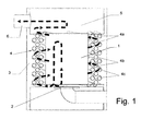
figure 1 représente une coupe générale schématique levée d'une chaudière pourvue de l'échangeur de chaleur de gaz conformément à l'invention, en tant qu'un exemple non restrictif de réalisation. Dans cette figure, des flèches indiquent le chemin que suivent les gaz dans leur refroidissement, depuis la chambre de combustion (1) jusqu'à la chambre de récupération de gaz (5) à travers les conduits tubulaires (4) à la configuration en spirale ou hélicoïde.
- The
figure 1 is a schematic general sectional view of a boiler provided with the gas heat exchanger according to the invention, as a non-restrictive embodiment. In this figure, arrows indicate the path followed by the gases in their cooling, from the combustion chamber (1) to the gas recovery chamber (5) through the tubular ducts (4) to the spiral configuration or helicoid.
Ci-dessous est décrit un exemple de réalisation pratique, non restrictive, de la présente invention. D'autres modes de réalisation dans lesquels des changements accessoires ne dénaturant pas son fondement sont introduits ne sont absolument pas écartés.Below is an example of a practical, non-restrictive embodiment of the present invention. Other embodiments in which the incidental changes do not denature its foundation are introduced are absolutely not excluded.
Dans les dessins de cet exemple de réalisation préférentielle, les références et les particularités suivantes sont indiquées:
- 1.- Chambre de combustion
- 2.- Brûleur
- 3.- Circuit primaire d'eau
- 4.- Conduits tubulaires courbes
- 5.- Chambre de récupération de gaz
- 6.- Cheminée
- 1.- Combustion chamber
- 2.- Burner
- 3.- Primary water circuit
- 4.- Curved tubular ducts
- 5.- Gas recovery chamber
- 6.- Fireplace
L'objet de l'invention est un échangeur de chaleur de gaz, pour des chaudières de combustibles solides, du type de celles connues comme « à tubes de fumée ».The object of the invention is a gas heat exchanger for solid fuel boilers of the type known as "smoke tube".
Communément connues, ces chaudières sont constituées par une chambre de combustion (1) avec un ou plusieurs brûleurs (2) de combustibles solides qui produisent des gaz à haute température dans cette chambre de combustion (1). Pour profiter de la chaleur des gaz produits par la combustion, des conduits tubulaires droits sont disposés, dans lesquels les gaz avancent vers une chambre de récupération tandis qu'ils sont refroidis en échangeant leur chaleur avec un circuit primaire d'eau où ces conduits tubulaires droits sont immergés.Commonly known, these boilers are constituted by a combustion chamber (1) with one or more burners (2) of solid fuels that produce high temperature gases in the combustion chamber (1). To take advantage of the heat of the gases produced by the combustion, straight tubular ducts are arranged, in which the gases advance towards a recovery chamber while they are cooled by exchanging their heat with a primary circuit of water where these tubular ducts rights are immersed.
Conformément à l'invention et selon la réalisation représentée, un ou plusieurs conduits tubulaires courbés (4) sont disposés, immergés dans le circuit primaire d'eau (3) et en enlaçant tout le périmètre de la chambre de combustion (1).According to the invention and according to the embodiment shown, one or more curved tubular ducts (4) are arranged, immersed in the primary water circuit (3) and embracing the entire perimeter of the combustion chamber (1).
L'échangeur de chaleur de gaz, conformément à l'invention, peut se composer indifféremment de:
- un seul conduit tubulaire (4) de configuration en spirale ou hélicoïde qui enlace toute ou la plus grande partie du périmètre de la chambre de combustion (1);
- plusieurs conduits tubulaires (4) de configuration en spirale ou hélicoïde, entrelacés en enlaçant toute ou la plus grande partie du périmètre de la chambre de combustion (1); ou
- plusieurs circuits indépendants (4a), (4b), (4c) de configuration en spirale ou hélicoïde, entrelacés et enlaçant toute ou la plus grande partie du périmètre de la chambre de combustion (1).
- a single tubular duct (4) of spiral or helical configuration which embraces all or most of the perimeter of the combustion chamber (1);
- a plurality of tubular conduits (4) of spiral or helical configuration, interlaced by embracing all or most of the perimeter of the combustion chamber (1); or
- several independent circuits (4a), (4b), (4c) of spiral or helical configuration, interlaced and embracing all or most of the perimeter of the combustion chamber (1).
La condition est que ces conduits tubulaires (4) en spirale ou en forme hélicoïde partent de la chambre de combustion (1) depuis laquelle ils reçoivent les gaz chauds ; qu'ils enlacent le périmètre de la chambre de combustion (1) tant qu'ils sont immergés dans le circuit primaire d'eau (3) qui l'entoure, pour échanger de la chaleur avec celle-ci et refroidir, et qu'ils atteignent la chambre de récupération de gaz (5), où ceux-ci arrivent, froids ou presque froids, pour être évacués à travers la cheminée (6).The condition is that these tubular ducts (4) in spiral or helical form leave the combustion chamber (1) from which they receive the hot gases; they surround the perimeter of the combustion chamber (1) as long as they are immersed in the surrounding primary water circuit (3), to exchange heat with it and to cool, and they reach the gas recovery chamber (5), where they arrive, cold or almost cold, to be evacuated through the chimney (6).
De préférence, plusieurs sous-circuits (4a), (4b), (4c) sont disposés, indépendants et intercalés pour former un assemblage général autour du périmètre de la chambre de combustion (1). Ces sous-circuits, de configuration en spirale ou hélicoïdale, convergent dans une entrée et une sortie communes de sorte qu'une surface maximum d'échange de chaleur soit obtenue et, par conséquent, une optimisation du rendement de la chaudière.Preferably, several sub-circuits (4a), (4b), (4c) are arranged, independent and interposed to form a general assembly around the perimeter of the combustion chamber (1). These sub-circuits, of spiral or helical configuration, converge in a common inlet and outlet so that a maximum heat exchange area is obtained and, therefore, an optimization of the efficiency of the boiler.
Avec cette structure, composants et disposition d'éléments:
- les gaz chauds, produits dans la chambre de combustion (1) accèdent aux conduits tubulaires (4) en circulant à l'intérieur des différents sous-circuits (4a), (4b), (4c) vers la chambre de récupération de gaz (5);
- les sous-circuits (4a), (4b), (4c) sont immergés dans le circuit primaire d'eau (3) et entourent la chambre de combustion (1). Dans cette avancée des gaz vers la chambre de récupération de gaz (5) ils sont refroidis et réchauffent l'eau du circuit primaire (3);
- les gaz refroidis, froids ou presque froids, sont évacués vers l'extérieur depuis la chambre de récupération (5) à travers la cheminée (6);
- the hot gases produced in the combustion chamber (1) access the tubular ducts (4) circulating inside the different sub-circuits (4a), (4b), (4c) towards the gas recovery chamber ( 5);
- the sub-circuits (4a), (4b), (4c) are immersed in the primary water circuit (3) and surround the combustion chamber (1). In this advance of gases to the gas recovery chamber (5) they are cooled and heat the water of the primary circuit (3);
- the cooled, cold or almost cold gases are discharged outwards from the recovery chamber (5) through the chimney (6);
Avec cet échangeur de chaleur de gaz, l'on se sert de l'énergie des gaz produits dans la combustion des solides, en augmentant le rendement de la chaudière sans variation significative des dimensions.With this gas heat exchanger, the energy of the gases produced in the combustion of the solids is used, increasing the efficiency of the boiler without significant variation in dimensions.
Les matériaux, les dimensions, proportions et, en général, tous les autres détails accessoires ou secondaires n'altérant pas, ni ne changeant ou ne modifiant pas le fondement proposé pourront être variables.The materials, dimensions, proportions and, in general, any other accessory or secondary details that do not alter or change or modify the proposed basis may vary.
Les termes dans lesquels est rédigé ce mémoire sont véritables et reflètent fidèlement l'objet décrit, ceux-ci devant être entendus dans leur sens le plus vaste et ceci jamais de manière restrictive.The terms in which this memoir is written are true and faithfully reflect the object described, which must be understood in their broadest sense and never in a restrictive manner.
Claims (4)
Applications Claiming Priority (1)
| Application Number | Priority Date | Filing Date | Title |
|---|---|---|---|
| ES201330480 | 2013-04-23 |
Publications (2)
| Publication Number | Publication Date |
|---|---|
| EP2799792A2 true EP2799792A2 (en) | 2014-11-05 |
| EP2799792A3 EP2799792A3 (en) | 2014-11-19 |
Family
ID=49911371
Family Applications (1)
| Application Number | Title | Priority Date | Filing Date |
|---|---|---|---|
| EP13380054.0A Withdrawn EP2799792A3 (en) | 2013-04-23 | 2013-11-25 | Gas heat exchanger, for solid combustion boilers |
Country Status (1)
| Country | Link |
|---|---|
| EP (1) | EP2799792A3 (en) |
Citations (3)
| Publication number | Priority date | Publication date | Assignee | Title |
|---|---|---|---|---|
| ES312179A1 (en) | 1965-04-23 | 1966-01-01 | Constructora Field Soc Anenima | Vertical steam generator pirotubular. (Machine-translation by Google Translate, not legally binding) |
| ES2156689A1 (en) | 1998-12-11 | 2001-07-01 | Vulcano Sadeca S A | Hot water generator for operation at low temperature |
| ES1059434U (en) | 2005-01-24 | 2005-04-16 | Aspiraciones Zamoranas Miz, S.A. | Biomass boiler (Machine-translation by Google Translate, not legally binding) |
Family Cites Families (8)
| Publication number | Priority date | Publication date | Assignee | Title |
|---|---|---|---|---|
| DE345607C (en) * | 1920-08-07 | 1922-06-08 | Moll Werke Akt Ges | Filling shaft boiler with a helical heating channel |
| DE1113294B (en) * | 1958-08-27 | 1961-08-31 | Schoppe Fritz | Boiler with a cylindrical combustion chamber |
| FR2244140A1 (en) * | 1973-09-14 | 1975-04-11 | Gordeladze Oreste | Gas or oil fired central heating boiler - gases travel down through coil around combustion chamber |
| FR2479956A1 (en) * | 1980-04-02 | 1981-10-09 | Collard Trolart Sa | Domestic water heater - boiler - has spiral flue tube in parallel sections passing downwards through water |
| KR810001688Y1 (en) * | 1980-07-28 | 1981-10-27 | 박기동 | Hot water boiler including radial shape absorption combustion gas |
| US4641631A (en) * | 1983-07-20 | 1987-02-10 | Columbia Gas System Service Corporation | Apparatus and method for burning a combustible gas, and a heat exchanger for use in this apparatus |
| GB8422811D0 (en) * | 1984-09-10 | 1984-10-17 | Burco Dean Ltd | Water heating apparatus |
| DE20220413U1 (en) * | 2002-09-10 | 2003-06-26 | Wolf Gmbh | Useful output boiler has corrugated heat tubes run with turbulent flow profile, and heat exchanger tubes are of different lengths and in predetermined area arranged concentrically to one another |
-
2013
- 2013-11-25 EP EP13380054.0A patent/EP2799792A3/en not_active Withdrawn
Patent Citations (4)
| Publication number | Priority date | Publication date | Assignee | Title |
|---|---|---|---|---|
| ES312179A1 (en) | 1965-04-23 | 1966-01-01 | Constructora Field Soc Anenima | Vertical steam generator pirotubular. (Machine-translation by Google Translate, not legally binding) |
| ES2156689A1 (en) | 1998-12-11 | 2001-07-01 | Vulcano Sadeca S A | Hot water generator for operation at low temperature |
| ES2237230A1 (en) | 1998-12-11 | 2005-07-16 | Vulcano-Sadeca S.A. | Hot water generator for operation at low temperature |
| ES1059434U (en) | 2005-01-24 | 2005-04-16 | Aspiraciones Zamoranas Miz, S.A. | Biomass boiler (Machine-translation by Google Translate, not legally binding) |
Also Published As
| Publication number | Publication date |
|---|---|
| EP2799792A3 (en) | 2014-11-19 |
Similar Documents
| Publication | Publication Date | Title |
|---|---|---|
| EP2795073B1 (en) | Method an cogeneration plant with thermocompression | |
| EP1953479A2 (en) | Device for cooling an electrical device in a turbomachine | |
| CA3011196A1 (en) | Condensation heat exchanger provided with a heat exchange device | |
| FR3016027A1 (en) | THERMAL EXCHANGER COMPRISING A GRID | |
| FR2988822A1 (en) | Heat exchanger for gas turbine of rotary wing aircraft i.e. helicopter, has set of plates stacked such that two sets of plates are adjacent in upper plane, where ridges and hollow sections of adjacent plates form acute angle | |
| FR2480924A1 (en) | HEAT EXCHANGER WITH FINS | |
| EP1875130B1 (en) | Double wall extension | |
| EP2799792A2 (en) | Gas heat exchanger, for solid combustion boilers | |
| EP3015807A1 (en) | Heat exchanger spacer | |
| FR2514475A1 (en) | Heat exchanger heating boiler - has axial heating coil with heat exchange disc between coils | |
| EP2012073B1 (en) | Heat exchanger for a boiler, boiler having such a heat exchanger and method for producing such a heat exchanger | |
| EP3354997B1 (en) | Boiler with improved efficiency | |
| FR2959000A1 (en) | CONDUIT FOR AN EVAPORATION CIRCUIT FOR COMBUSTION PRODUCTS AND COMBUSTION AIR SUPPLIES IN A FUMING FACILITY | |
| FR3090082A1 (en) | Apparatus for separating or liquefying a gas operating at cryogenic temperatures. | |
| FR3022334A1 (en) | THERMAL EXCHANGER WITH RECIRCULATION FLUID, SAID AT ECOPES | |
| EP2799666A2 (en) | Volute casing with two volumes for gas turbine | |
| FR3107732A1 (en) | REGULATION SYSTEM INCLUDING A VALVE, A REGULATOR, AN ACTUATOR AND A COOLING SYSTEM USING HEAT PIPE TUBES | |
| EP1593925B1 (en) | Plate heat exchanger | |
| EP0030183B1 (en) | Heating element for gas-fired domestic hot-water central-heating boilers | |
| FR3025303A1 (en) | RECIRCULATING FLUID HEAT EXCHANGER, SAID AT ECOPE, IN PLATE PRESENTATION | |
| WO1982001582A1 (en) | Heat exchanger for domestic central heating boilers | |
| EP1464907A1 (en) | Heat exchanger with a finned tube helically coiled and boiler comprising such a heat exchanger | |
| CH177035A (en) | Heat exchange apparatus and method of manufacturing this apparatus. | |
| CN104676908A (en) | Solar heat absorber with radial pin fin structure | |
| FR3026469A1 (en) | ANNULAR ROOM OF COMBUSTION CHAMBER WITH REGULAR AIR SUPPLY LOCALLY |
Legal Events
| Date | Code | Title | Description |
|---|---|---|---|
| PUAL | Search report despatched |
Free format text: ORIGINAL CODE: 0009013 |
|
| PUAI | Public reference made under article 153(3) epc to a published international application that has entered the european phase |
Free format text: ORIGINAL CODE: 0009012 |
|
| 17P | Request for examination filed |
Effective date: 20131125 |
|
| AK | Designated contracting states |
Kind code of ref document: A2 Designated state(s): AL AT BE BG CH CY CZ DE DK EE ES FI FR GB GR HR HU IE IS IT LI LT LU LV MC MK MT NL NO PL PT RO RS SE SI SK SM TR |
|
| AX | Request for extension of the european patent |
Extension state: BA ME |
|
| AK | Designated contracting states |
Kind code of ref document: A3 Designated state(s): AL AT BE BG CH CY CZ DE DK EE ES FI FR GB GR HR HU IE IS IT LI LT LU LV MC MK MT NL NO PL PT RO RS SE SI SK SM TR |
|
| AX | Request for extension of the european patent |
Extension state: BA ME |
|
| RIC1 | Information provided on ipc code assigned before grant |
Ipc: F24H 1/28 20060101AFI20141010BHEP |
|
| STAA | Information on the status of an ep patent application or granted ep patent |
Free format text: STATUS: THE APPLICATION IS DEEMED TO BE WITHDRAWN |
|
| 18D | Application deemed to be withdrawn |
Effective date: 20150520 |