EP2799788A1 - Outdoor unit for refrigeration apparatus - Google Patents
Outdoor unit for refrigeration apparatus Download PDFInfo
- Publication number
- EP2799788A1 EP2799788A1 EP12862960.7A EP12862960A EP2799788A1 EP 2799788 A1 EP2799788 A1 EP 2799788A1 EP 12862960 A EP12862960 A EP 12862960A EP 2799788 A1 EP2799788 A1 EP 2799788A1
- Authority
- EP
- European Patent Office
- Prior art keywords
- aluminum
- bracket
- heat exchanger
- outdoor unit
- refrigeration apparatus
- Prior art date
- Legal status (The legal status is an assumption and is not a legal conclusion. Google has not performed a legal analysis and makes no representation as to the accuracy of the status listed.)
- Granted
Links
Images








Classifications
-
- F—MECHANICAL ENGINEERING; LIGHTING; HEATING; WEAPONS; BLASTING
- F28—HEAT EXCHANGE IN GENERAL
- F28F—DETAILS OF HEAT-EXCHANGE AND HEAT-TRANSFER APPARATUS, OF GENERAL APPLICATION
- F28F21/00—Constructions of heat-exchange apparatus characterised by the selection of particular materials
- F28F21/08—Constructions of heat-exchange apparatus characterised by the selection of particular materials of metal
- F28F21/081—Heat exchange elements made from metals or metal alloys
- F28F21/084—Heat exchange elements made from metals or metal alloys from aluminium or aluminium alloys
-
- F—MECHANICAL ENGINEERING; LIGHTING; HEATING; WEAPONS; BLASTING
- F24—HEATING; RANGES; VENTILATING
- F24F—AIR-CONDITIONING; AIR-HUMIDIFICATION; VENTILATION; USE OF AIR CURRENTS FOR SCREENING
- F24F1/00—Room units for air-conditioning, e.g. separate or self-contained units or units receiving primary air from a central station
- F24F1/06—Separate outdoor units, e.g. outdoor unit to be linked to a separate room comprising a compressor and a heat exchanger
- F24F1/14—Heat exchangers specially adapted for separate outdoor units
- F24F1/16—Arrangement or mounting thereof
-
- F—MECHANICAL ENGINEERING; LIGHTING; HEATING; WEAPONS; BLASTING
- F28—HEAT EXCHANGE IN GENERAL
- F28F—DETAILS OF HEAT-EXCHANGE AND HEAT-TRANSFER APPARATUS, OF GENERAL APPLICATION
- F28F1/00—Tubular elements; Assemblies of tubular elements
- F28F1/10—Tubular elements and assemblies thereof with means for increasing heat-transfer area, e.g. with fins, with projections, with recesses
- F28F1/12—Tubular elements and assemblies thereof with means for increasing heat-transfer area, e.g. with fins, with projections, with recesses the means being only outside the tubular element
- F28F1/126—Tubular elements and assemblies thereof with means for increasing heat-transfer area, e.g. with fins, with projections, with recesses the means being only outside the tubular element consisting of zig-zag shaped fins
- F28F1/128—Fins with openings, e.g. louvered fins
-
- F—MECHANICAL ENGINEERING; LIGHTING; HEATING; WEAPONS; BLASTING
- F28—HEAT EXCHANGE IN GENERAL
- F28F—DETAILS OF HEAT-EXCHANGE AND HEAT-TRANSFER APPARATUS, OF GENERAL APPLICATION
- F28F19/00—Preventing the formation of deposits or corrosion, e.g. by using filters or scrapers
-
- F—MECHANICAL ENGINEERING; LIGHTING; HEATING; WEAPONS; BLASTING
- F28—HEAT EXCHANGE IN GENERAL
- F28F—DETAILS OF HEAT-EXCHANGE AND HEAT-TRANSFER APPARATUS, OF GENERAL APPLICATION
- F28F9/00—Casings; Header boxes; Auxiliary supports for elements; Auxiliary members within casings
-
- F—MECHANICAL ENGINEERING; LIGHTING; HEATING; WEAPONS; BLASTING
- F28—HEAT EXCHANGE IN GENERAL
- F28F—DETAILS OF HEAT-EXCHANGE AND HEAT-TRANSFER APPARATUS, OF GENERAL APPLICATION
- F28F9/00—Casings; Header boxes; Auxiliary supports for elements; Auxiliary members within casings
- F28F9/001—Casings in the form of plate-like arrangements; Frames enclosing a heat exchange core
- F28F9/002—Casings in the form of plate-like arrangements; Frames enclosing a heat exchange core with fastening means for other structures
-
- F—MECHANICAL ENGINEERING; LIGHTING; HEATING; WEAPONS; BLASTING
- F28—HEAT EXCHANGE IN GENERAL
- F28F—DETAILS OF HEAT-EXCHANGE AND HEAT-TRANSFER APPARATUS, OF GENERAL APPLICATION
- F28F9/00—Casings; Header boxes; Auxiliary supports for elements; Auxiliary members within casings
- F28F9/007—Auxiliary supports for elements
-
- F—MECHANICAL ENGINEERING; LIGHTING; HEATING; WEAPONS; BLASTING
- F28—HEAT EXCHANGE IN GENERAL
- F28F—DETAILS OF HEAT-EXCHANGE AND HEAT-TRANSFER APPARATUS, OF GENERAL APPLICATION
- F28F9/00—Casings; Header boxes; Auxiliary supports for elements; Auxiliary members within casings
- F28F9/02—Header boxes; End plates
- F28F9/0243—Header boxes having a circular cross-section
-
- F—MECHANICAL ENGINEERING; LIGHTING; HEATING; WEAPONS; BLASTING
- F28—HEAT EXCHANGE IN GENERAL
- F28F—DETAILS OF HEAT-EXCHANGE AND HEAT-TRANSFER APPARATUS, OF GENERAL APPLICATION
- F28F2215/00—Fins
- F28F2215/12—Fins with U-shaped slots for laterally inserting conduits
Definitions
- the refrigeration apparatus configured by connecting the outdoor unit 2, the indoor unit 3, and the refrigerant connection tubes 6 and 7, the refrigeration apparatus has a configuration wherein a compressor 11, a four-way switching valve 12, an outdoor heat exchanger 13, an expansion valve 14, an indoor heat exchanger 4, and an accumulator 15 and the like are interconnected by refrigerant tubes.
- the refrigeration apparatus is charged with refrigerant, and a refrigeration cycle operation is performed wherein the refrigerant is compressed, is cooled, has its pressure reduced, is heated and evaporated, and is thereafter compressed again.
- a liquid refrigerant-side stop valve 17 and a gas refrigerant-side stop valve 18 of the outdoor unit 2 that are connected to the refrigerant connection tubes 6 and 7, respectively, are placed in an open state.
- the four-way switching valve 12 is switched to a state indicated by the dashed lines in FIG. 1 , that is, a state in which the discharge side of the compressor 11 is connected to the gas side of the indoor heat exchanger 4 via the gas refrigerant-side stop valve 18 and the refrigerant connection tube 7 and in which the suction side of the compressor 11 is connected to the gas side of the outdoor heat exchanger 13.
- the air conditioning apparatus 1 causes the indoor heat exchanger 4 to function as a condenser of the refrigerant compressed in the compressor 11 and causes the outdoor heat exchanger 13 to function as an evaporator of the refrigerant that has been condensed in the indoor heat exchanger 4.
- the outdoor heat exchanger 13 made of aluminum is, in order to prevent corrosion, attached by later-described brackets or the like made of aluminum to the unit casing 20 in such a way that the outdoor heat exchanger 13 does not directly contact the top panel 21, the bottom panel 22, the blower chamber-side side panel 23, the machine chamber-side side panel 24, and the partition panel 28 and the like that are made of sheet steel.
- One end of the outdoor heat exchanger 13 is connected to the four-way switching valve 12, and the other end of the outdoor heat exchanger 13 is connected to the expansion valve 14.
- the multi-hole flat tubes 33 which are slightly thicker than the up and down width of the cutouts 32a, are arranged in plural tiers spaced apart from one another in a state in which the planar portions face up and down (a state in which the side surfaces of the multi-hole flat tubes 33 are arranged opposing one another), and the multi-hole flat tubes 33 are temporarily fixed in a state in which they have been fitted into the cutouts 32a.
- the heat transfer fins 32 and the multi-hole flat tubes 33 are brazed together in a state in which the multi-hole flat tubes 33 have been fitted into the cutouts 32a in the heat transfer fins 32 in this way. Furthermore, both ends of each of the multi-hole flat tubes 33 are fitted into and brazed to the header collection tubes 34 and 35.
- FIGS. 8(a) to 8(d) show the bracket 40 made of aluminum for attaching the outdoor heat exchanger 13 to the blower chamber-side side panel 23.
- FIG. 8(a) is a perspective view of the bracket 40 made of aluminum
- FIG. 8(b) is a plan view of the bracket 40
- FIG. 8(c) is a front view of the bracket 40
- FIG. 8(d) is a side view of the bracket 40.
- FIG. 11 (a) is a plan view of the resin cover
- FIG. 11(b) is a front view of the resin cover
- FIG. 11(c) is a bottom view of the resin cover
- FIG. 12(a) is a left side view of the resin cover
- FIG. 12(b) is a back view of the resin cover
- FIG. 12(c) is a right side view of the resin cover
- FIG. 13(a) is a sectional view taken along line I-I of FIG. 12(b) as seen from the direction of the arrows
- FIG. 13(b) is a sectional view taken along line II-II of FIG. 12(b) as seen from the direction of the arrows
- FIG. 13(c) is a partially enlarged sectional view taken along line III-III of FIG. 12(c) as seen from the direction of the arrows.
- the male screws can be fastened to the screw holes 72a, 73a, and 73b in the attachment plate 70 in such a way that the male screws are not brought into contact with the brackets 40 and 50 and the resin cover 60.
- the screw holes 72a, 73a, and 73b are formed by burring.
Landscapes
- Engineering & Computer Science (AREA)
- Physics & Mathematics (AREA)
- Mechanical Engineering (AREA)
- General Engineering & Computer Science (AREA)
- Thermal Sciences (AREA)
- Geometry (AREA)
- Chemical & Material Sciences (AREA)
- Combustion & Propulsion (AREA)
- Other Air-Conditioning Systems (AREA)
Abstract
Description
- The present invention relates to an outdoor unit of a refrigeration apparatus and particularly an outdoor unit of a refrigeration apparatus equipped with a heat exchanger made of aluminum or aluminum alloy.
- In recent years, in order to make heat exchangers lighter in weight, aluminum and aluminum alloys have sometimes been used not just for the fins of the heat exchanger but also for the heat transfer tubes and the header collection tubes of the heat exchanger. At the same time, the heat exchanger made of aluminum or aluminum alloy is housed in a casing of an outdoor unit, for example, and because of advantages such as processing ease and cost it is common for a non-aluminum metal different from aluminum or aluminum alloy, such as sheet steel for example, to be used for the casing.
- Direct contact between the non-aluminum metal and the heat exchanger made of aluminum or aluminum alloy leads to corrosion of the heat exchanger. Therefore, as described in patent document 1 (
JP-A No. H7-234088 - However, in this configuration, the section where the bracket made of aluminum or aluminum alloy and the non-aluminum metal contact one another causes corrosion of the bracket made of aluminum or aluminum alloy. Corrosion of the bracket made of aluminum or aluminum alloy triggers problems such as a poor outer appearance and looseness of the attachment of the heat exchanger.
- It is an object of the present invention to prevent corrosion of a bracket made of aluminum or aluminum alloy for attaching a heat exchanger made of aluminum or aluminum alloy.
- An outdoor unit of a refrigeration apparatus pertaining to a first aspect of the present invention is an outdoor unit of a refrigeration apparatus comprising a heat exchanger made of aluminum or aluminum alloy, a bracket made of aluminum or aluminum alloy that has a securing portion that is attached directly to the heat exchanger and a fixing portion that has a through hole for fixing the bracket to a structural part made of a non-aluminum metal, and a non-metal component that is interposed between the fixing portion of the bracket and the structural part that are fixed to one another and is for placing both in a non-contact state, the outdoor unit of the refrigeration apparatus further comprising: an anchoring part made of a non-aluminum metal that has an outer shape that is smaller than the through hole in the fixing portion; and an anchored structure that cooperates with the anchoring part to fasten the fixing portion of the bracket to the structural part via the non-metal component, wherein the non-metal component maintains, in a state in which the anchoring part is passing through the through hole in the fixing portion, a non-contact state between the bracket made of aluminum or aluminum alloy and the anchoring part made of a non-aluminum metal.
- The non-metal component here includes a member comprising a polymer material, such as a resin member or a rubber member, and a member comprising a non-metal inorganic material, such as a ceramic member.
- In the outdoor unit of the refrigeration apparatus pertaining to the first aspect, in a state in which the bracket made of aluminum or aluminum alloy is fixed to, and without contacting, the structural part made of a non-aluminum metal via the non-metal component, the non-metal component can maintain the anchoring part, whose outer shape is smaller than the outer shape of the through hole, in a non-contact state relative to the bracket made of aluminum or aluminum alloy. Because the anchoring part made of a non-aluminum metal does not contact the bracket made of aluminum or aluminum alloy, corrosion of the bracket caused by corrosion occurring between the non-aluminum metal and the aluminum metal is prevented.
- An outdoor unit of a refrigeration apparatus pertaining to a second aspect of the present invention is the outdoor unit of the refrigeration apparatus pertaining to the first aspect, further comprising a casing made of a non-aluminum metal for housing the heat exchanger made of aluminum or aluminum alloy, wherein the casing made of a non-aluminum metal is the structural part made of a non-aluminum metal.
- In the outdoor unit of the refrigeration apparatus pertaining to the second aspect, the bracket made of aluminum or aluminum alloy can fix the casing made of a non-aluminum metal via the non-metal component.
- An outdoor unit of a refrigeration apparatus pertaining to a third aspect of the present invention is the outdoor unit of the refrigeration apparatus pertaining to the second aspect, wherein the non-metal component has a sandwiching structure that sandwiches from both sides the fixing portion of the bracket made of aluminum or aluminum alloy, and the anchoring part and the anchored structure fasten together the sandwiching structure of the non-metal component and the fixing portion of the bracket made of aluminum or aluminum alloy.
- In the outdoor unit of the refrigeration apparatus pertaining to the third aspect, the fixing portion of the bracket is fastened in a state in which it is sandwiched by the sandwiching structure of the non-metal component, so the bracket can be strongly fixed by the non-metal component, and the fixing of the heat exchanger can be strengthened.
- An outdoor unit of a refrigeration apparatus pertaining to a fourth aspect of the present invention is the outdoor unit of the refrigeration apparatus of the third aspect, wherein the anchoring part is a male screw made of a non-aluminum metal, and the anchored structure is a nut separate from the structural part and capable of anchoring the male screw, an attachment plate having a screw hole capable of anchoring the male screw, or a female-threaded portion in the non-metal component capable of anchoring the male screw.
- In the outdoor unit of the refrigeration apparatus pertaining to the fourth aspect, by using the male screw made of a non-aluminum metal, an anchoring part having the necessary strength can be obtained at a low cost.
- An outdoor unit of a refrigeration apparatus pertaining to a fifth aspect of the present invention is the outdoor unit of the refrigeration apparatus pertaining to the fourth aspect, wherein the screw hole in the attachment plate is burred.
- In the outdoor unit of the refrigeration apparatus pertaining to the fifth aspect, the screw hole is burred, so the male screw can be tightened in just the attachment plate, and the number of parts can be reduced.
- An outdoor unit of a refrigeration apparatus pertaining to a sixth aspect of the present invention is any of the outdoor units of the refrigeration apparatus of any of the first aspect to the fifth aspect, wherein the bracket made of aluminum or aluminum alloy has a plurality of the fixing portions.
- In the outdoor unit of the refrigeration apparatus pertaining to the sixth aspect, the fixing of the bracket can be performed at plural places using the plural fixing portions, so the stability of the fixing of the heat exchanger can be improved.
- In the outdoor unit of the refrigeration apparatus pertaining to the first aspect, corrosion of the bracket made of aluminum or aluminum alloy for attaching the heat exchanger made of aluminum or aluminum alloy can be prevented, and problems such as a poor outer appearance and looseness occurring in the attachment of the heat exchanger due to such corrosion or the like can be prevented from being triggered.
- In the outdoor unit of the refrigeration apparatus pertaining to the second aspect, it becomes easier to make the outdoor unit compact.
- In the outdoor unit of the refrigeration apparatus pertaining to the third aspect, the fixing of the heat exchanger can be strengthened by the sandwiching structure of the non-metal component, and the effect of preventing the occurrence of problems such as looseness of the attachment of the heat exchanger can be improved.
- In the outdoor unit of the refrigeration apparatus pertaining to the fourth aspect, the outdoor unit can be provided at a low cost because an anchoring part having the necessary strength can be obtained at a low cost.
- In the outdoor unit of the refrigeration apparatus pertaining to the fifth aspect, the number of parts can be reduced and the manufacturing cost of the outdoor unit can be reduced.
- In the outdoor unit of the refrigeration apparatus pertaining to the sixth aspect, the fixing of the heat exchanger becomes stable, so problems such as the occurrence of noise resulting from rattling of the heat exchanger can be prevented.
-
-
FIG. 1 is a circuit diagram for describing an overview of the configuration of an air conditioning apparatus pertaining to an embodiment; -
FIG. 2 is a perspective view showing the outer appearance of an outdoor unit; -
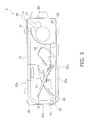
FIG. 3 is a schematic plan view showing the outdoor unit in a state in which a top panel has been removed; -
FIG. 4 is a schematic back view showing the general configuration of an outdoor heat exchanger; -
FIG. 5 is a partial sectional view for describing the configuration of the outdoor heat exchanger; -
FIG. 6 is an enlarged sectional view for describing the configuration of a heat exchange section of the outdoor heat exchanger; -
FIG. 7 is an enlarged side view of a blower chamber-side side panel; -
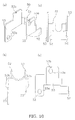
FIG. 8(a) is a perspective view showing one aspect of a bracket made of aluminum,FIG. 8(b) is a plan view of the bracket,FIG. 8(c) is a front view of the bracket, andFIG. 8(d) is a side view of the bracket; -
FIG. 9 is a partially enlarged perspective view showing the bracket brazed to a header collection tube; -
FIG. 10(a) is a perspective view showing another aspect of a bracket made of aluminum,FIG. 10(b) is a plan view of the bracket,FIG. 10(c) is a front view of the bracket, andFIG. 10(d) is a side view of the bracket; -
FIG. 11 (a) is a plan view of a resin cover,FIG. 11 (b) is a front view of the resin cover, andFIG. 11(c) is a bottom view of the resin cover; -
FIG. 12(a) is a left side view of the resin cover,FIG. 12(b) is a back view of the resin cover, andFIG. 12(c) is a right side view of the resin cover; -
FIG. 13(a) is a sectional view taken along line I-I ofFIG. 12(b) as seen from the direction of the arrows,FIG. 13(b) is a sectional view taken along line II-II ofFIG. 12(b) as seen from the direction of the arrows, andFIG. 13(c) is a sectional view taken along line III-III ofFIG. 12(c) as seen from the direction of the arrows; -
FIG. 14(a) is a plan view of an attachment plate, andFIG. 14(b) is a front view of the attachment plate; -
FIG. 15(a) is a left side view of the attachment plate, andFIG. 15(b) is a right side view of the attachment plate; -
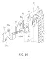
FIG. 16 is an exploded assembly diagram of the bracket and the resin cover; -
FIG. 17 is a perspective view showing a state in which the bracket, the resin cover, and the attachment plate are attached; and -
FIG. 18 is a perspective view showing a state of the outdoor unit in which panels of a unit casing other than a bottom panel have been removed. - A refrigeration apparatus used in an air conditioning apparatus will be described as a refrigeration apparatus pertaining to an embodiment of the present invention.
FIG. 1 is a circuit diagram showing an overview of an air conditioning apparatus. Anair conditioning apparatus 1 is configured by anoutdoor unit 2 and anindoor unit 3. Theair conditioning apparatus 1 is an apparatus used to cool and heat rooms in a building by performing a vapor compression refrigeration cycle operation. Theair conditioning apparatus 1 is equipped with theoutdoor unit 2 that serves as a heat source unit, theindoor unit 3 that serves as a utilization unit, and refrigerant connection tubes 6 and 7 that interconnect theoutdoor unit 2 and theindoor unit 3. - In the
air conditioning apparatus 1 configured by connecting theoutdoor unit 2, theindoor unit 3, and the refrigerant connection tubes 6 and 7, the refrigeration apparatus has a configuration wherein acompressor 11, a four-way switching valve 12, anoutdoor heat exchanger 13, anexpansion valve 14, anindoor heat exchanger 4, and anaccumulator 15 and the like are interconnected by refrigerant tubes. The refrigeration apparatus is charged with refrigerant, and a refrigeration cycle operation is performed wherein the refrigerant is compressed, is cooled, has its pressure reduced, is heated and evaporated, and is thereafter compressed again. During operation, a liquid refrigerant-side stop valve 17 and a gas refrigerant-side stop valve 18 of theoutdoor unit 2 that are connected to the refrigerant connection tubes 6 and 7, respectively, are placed in an open state. - During the cooling operation, the four-
way switching valve 12 is switched to a state indicated by the solid lines inFIG. 1 , that is, a state in which the discharge side of thecompressor 11 is connected to the gas side of theoutdoor heat exchanger 13 and in which the suction side of thecompressor 11 is connected to the gas side of theindoor heat exchanger 4 via theaccumulator 15, the gas refrigerant-side stop valve 18, and the refrigerant connection tube 7. In the cooling operation, theair conditioning apparatus 1 causes theoutdoor heat exchanger 13 to function as a condenser of the refrigerant compressed in thecompressor 11 and causes theindoor heat exchanger 4 to function as an evaporator of the refrigerant that has been condensed in theoutdoor heat exchanger 13. - During the heating operation, the four-
way switching valve 12 is switched to a state indicated by the dashed lines inFIG. 1 , that is, a state in which the discharge side of thecompressor 11 is connected to the gas side of theindoor heat exchanger 4 via the gas refrigerant-side stop valve 18 and the refrigerant connection tube 7 and in which the suction side of thecompressor 11 is connected to the gas side of theoutdoor heat exchanger 13. In the heating operation, theair conditioning apparatus 1 causes theindoor heat exchanger 4 to function as a condenser of the refrigerant compressed in thecompressor 11 and causes theoutdoor heat exchanger 13 to function as an evaporator of the refrigerant that has been condensed in theindoor heat exchanger 4. - The
indoor unit 3 is installed as a result of being mounted on a wall surface in a room or being embedded in or suspended from a ceiling in a room of a building or the like. Theindoor unit 3 has theindoor heat exchanger 4 and an indoor fan 5. Theindoor heat exchanger 4 is, for example, a cross fin type fin-and-tube heat exchanger configured by heat transfer tubes and numerous fins; during the cooling operation, theindoor heat exchanger 4 functions as an evaporator of the refrigerant to cool the room air, and during the heating operation, theindoor heat exchanger 4 functions as a condenser of the refrigerant to heat the room air. - The
outdoor unit 2 is installed outside a building or the like and is connected to theindoor unit 3 installed in the room via the refrigerant connection tubes 6 and 7. As shown inFIG. 2 andFIG. 3 , theoutdoor unit 2 is equipped with a substantiallycuboidal unit casing 20. As shown inFIG. 3 , theoutdoor unit 2 has a structure (a so-called trunk structure) in which a blower chamber S1 and a machine chamber S2 are formed as a result of the inside space of theunit casing 20 being divided in two by apartition panel 28 extending in the vertical direction. As shown inFIG. 3 , theoutdoor heat exchanger 13 and anoutdoor fan 16 and the like are disposed in the blower chamber S1. Furthermore, thecompressor 11 and theaccumulator 15 shown inFIG. 3 and the four-way switching valve 12, theexpansion valve 14, the liquid refrigerant-side stop valve 17, and the gas refrigerant-side stop valve 18 and the like not shown inFIG. 3 are disposed in the machine chamber S2. - The
unit casing 20 is configured to include atop panel 21, abottom panel 22, a blower chamber-side side panel 23, a machine chamber-side side panel 24, a blower chamber-side front panel 25, and a machine chamber-side front panel 26. Thetop panel 21 is a panel member made of sheet steel that configures the top surface section of theunit casing 20. Thebottom panel 22 is a panel member made of sheet steel that configures the bottom surface section of theunit casing 20. The blower chamber-side side panel 23 is a panel member made of sheet steel that configures the side surface section of theunit casing 20 near the blower chamber S1. The machine chamber-side side panel 24 is a panel member made of sheet steel that configures part of the side surface section of theunit casing 20 near the machine chamber S2 and the back surface section of theunit casing 20 near the machine chamber S2. The blower chamber-side front panel 25 is a panel member made of sheet steel that configures the front surface section of theunit casing 20 in front of the blower chamber S1 and part of the front surface section of theunit casing 20 in front of the machine chamber S2. The blower chamber-side front panel 25 and the blower chamber-side side panel 23 may also be integrally formed by pressing and forming a single sheet of sheet steel. - The
outdoor unit 2 is configured to suck outdoor air into the blower chamber S1 inside the unit casing 20 from the a part of back surface and the side surface of theunit casing 20 and blow out the sucked-in outdoor air from the front surface of theunit casing 20. For that reason, anair inlet 20a for the outdoor air sucked into the blower chamber S1 inside theunit casing 20 is formed between the end portion of the blower chamber-side side panel 23 on the back surface side and the end portion of the machine chamber-side side panel 24 on the blower chamber S1 side, and anair inlet 20b for the outdoor air is formed in the blower chamber-side side panel 23. Furthermore, anair outlet 20c for blowing outside the outdoor air that has been sucked into the blower chamber S1 is disposed in the blower chamber-side front panel 25. The front side of theair outlet 20c is covered by afan grille 25a. - The
outdoor heat exchanger 13 is disposed standing in the up and down direction (vertical direction) in the blower chamber S1, which is a space covered by the blower chamber-side side panel 23, the blower chamber-side front panel 25, thepartition panel 28, and one section of the machine chamber-side side panel 24. Theoutdoor heat exchanger 13 has an L shape as seen in a plan view and opposes theair inlets outdoor heat exchanger 13 is a heat exchanger made of aluminum. Theoutdoor heat exchanger 13 made of aluminum is, in order to prevent corrosion, attached by later-described brackets or the like made of aluminum to theunit casing 20 in such a way that theoutdoor heat exchanger 13 does not directly contact thetop panel 21, thebottom panel 22, the blower chamber-side side panel 23, the machine chamber-side side panel 24, and thepartition panel 28 and the like that are made of sheet steel. One end of theoutdoor heat exchanger 13 is connected to the four-way switching valve 12, and the other end of theoutdoor heat exchanger 13 is connected to theexpansion valve 14. - Next, the configuration of the
outdoor heat exchanger 13 will be described in detail usingFIG. 4 ,FIG. 5 , andFIG. 6 . The heat exchanger made of aluminum is configured byheat transfer fins 32 made of aluminum, multi-holeflat tubes 33 made of aluminum, andheader collection tubes outdoor heat exchanger 13 is equipped with aheat exchange section 31 that causes heat exchange to be performed between the outdoor air and the refrigerant, and theheat exchange section 31 is configured by the numerousheat transfer fins 32 made of aluminum and the numerous multi-holeflat tubes 33 made of aluminum. Theheat exchange section 31 has an upperheat exchange section 31 a, in which are disposed gas refrigerant multi-holeflat tubes 33a that are included among the numerous multi-holeflat tubes 33 and are for allowing gas refrigerant or refrigerant in a gas-liquid multi-state to flow through when theoutdoor heat exchanger 13 functions as a condenser, and a lower heat exchange section 31b, in which are connected liquid refrigerant multi-holeflat tubes 33b that are included among the numerous multi-holeflat tubes 33 and are for allowing the refrigerant in the gas-liquid multi-state or liquid refrigerant to flow through. - The multi-hole
flat tubes 33 function as heat transfer tubes and cause the heat moving between theheat transfer fins 32 and the outdoor air to be exchanged between the refrigerant flowing inside and theheat transfer fins 32. - The
outdoor heat exchanger 13 is equipped with theheader collection tubes heat exchange section 31. Theheader collection tube 34 has a cylindrical pipe structure made of aluminum and has insidespaces baffle 34c made of aluminum. A heat exchanger-side gas tube 38 made of aluminum is connected to theinside space 34a in the upper portion of theheader collection tube 34, and a heat exchanger-side liquid tube 39 made of aluminum is connected to theinside space 34b in the lower portion of theheader collection tube 34. - The
header collection tube 35 has a cylindrical pipe structure made of aluminum, and insidespaces header collection tube 35 as a result of the inside space of theheader collection tube 35 being partitioned bybaffles flat tubes 33a connected to theinside space 34a in the upper portion of theheader collection tube 34 are connected to the three insidespaces header collection tube 35. Furthermore, the numerous liquid refrigerant multi-holeflat tubes 33b connected to theinside space 34b in the lower portion of theheader collection tube 34 are connected to the three insidespaces header collection tube 35. - Furthermore, the
inside space 35a and theinside space 35e of theheader collection tube 35 are interconnected by aconnection tube 36 made of aluminum, and theinside space 35b and theinside space 35d are interconnected by aconnection tube 37 made of aluminum. Theinside space 35c also fulfills the function of interconnecting part of the inside space in the upper portion of the heat exchange section 31 (the section connected to theinside space 34a) and part of the inside space in the lower portion of the heat exchange section 31 (the section connected to theinside space 34b). Because of these configurations, during the cooling operation (when theoutdoor heat exchanger 13 functions as a condenser) for example, the gas refrigerant supplied to theinside space 35a in the upper portion of theheader collection tube 35 by the heat exchanger-side gas tube 38 made of aluminum performs heat exchange in the upper portion of theheat exchange section 31, some of that refrigerant liquefies so that the refrigerant changes to a gas-liquid multi-state, the refrigerant in the gas-liquid multi-state doubles back in theheader collection tube 35 and travels through the lower portion of theheat exchange section 31 where the remaining gas refrigerant liquefies, and the liquid refrigerant exits through the heat exchanger-side liquid tube 39 made of aluminum. -
FIG. 6 is a partially enlarged view showing the cross-sectional structure of theheat exchange section 31 of theoutdoor heat exchanger 13 as cut by a plane perpendicular to the lengthwise direction of the multi-holeflat tubes 33. Theheat transfer fins 32 are flat plates made of thin aluminum, andplural cutouts 32a extending in the horizontal direction are formed adjacent to one another in the up and down direction in each of theheat transfer fins 32. The multi-holeflat tubes 33 have upper and lower planar portions serving as heat transfer surfaces and pluralinside flow paths 331 through which the refrigerant flows. The multi-holeflat tubes 33, which are slightly thicker than the up and down width of thecutouts 32a, are arranged in plural tiers spaced apart from one another in a state in which the planar portions face up and down (a state in which the side surfaces of the multi-holeflat tubes 33 are arranged opposing one another), and the multi-holeflat tubes 33 are temporarily fixed in a state in which they have been fitted into thecutouts 32a. Theheat transfer fins 32 and the multi-holeflat tubes 33 are brazed together in a state in which the multi-holeflat tubes 33 have been fitted into thecutouts 32a in theheat transfer fins 32 in this way. Furthermore, both ends of each of the multi-holeflat tubes 33 are fitted into and brazed to theheader collection tubes - The
inside spaces header collection tube 34 and theinside spaces header collection tube 35 are connected to theinside flow paths 331 in the multi-holeflat tubes 33. Baffle plates and the like for directing the flow of the refrigerant are disposed in theinside spaces header collection tube 34 and theinside spaces header collection tube 35, but description of details such as these will be omitted. -
FIG. 7 is an enlarged side view of the blower chamber-side side panel 23. Screw holes 23a and 23b are formed on the front side of theair inlet 20b in the blower chamber-side side panel 23 made of sheet steel.Brackets side side panel 23 bymale screws 80 or the like made of iron (seeFIG. 16 ) that are screwed into the screw holes 23a and 23b, whereby theheader collection tube 35 made of aluminum brazed to thebrackets -
FIGS. 8(a) to 8(d) show thebracket 40 made of aluminum for attaching theoutdoor heat exchanger 13 to the blower chamber-side side panel 23.FIG. 8(a) is a perspective view of thebracket 40 made of aluminum,FIG. 8(b) is a plan view of thebracket 40,FIG. 8(c) is a front view of thebracket 40, andFIG. 8(d) is a side view of thebracket 40. - The
bracket 40 is, for example, formed by pressing a single aluminum sheet. Two clampingpieces 42 that are attached to theheader collection tube 35 of theoutdoor heat exchanger 13 extend from abody portion 41 of thebracket 40. The clampingpieces 42 are each formed in a circular arc shape so as to conform to the outer periphery of the cylindricalheader collection tube 35. Twoattachment pieces 43 extend from the side of thebracket 40 opposite the side with the clampingpieces 42. A throughhole 43a for allowing a screw to pass through when attaching thebracket 40 to the blower chamber-side side panel 23 is disposed in each of theattachment pieces 43. The throughholes 43a are m1 ×n1 elongated holes. In order to position thebracket 40 and aresin cover 60,fitting counterparts 43b formed as a result of parts of the upper edge end portions of theattachment pieces 43 being cut out are disposed in theattachment pieces 43. Asensor retaining portion 44 formed in a concave shape is disposed in thebody portion 41. The shape of thesensor retaining portion 44 can be seen as forming atubular hole 44a and aslit 44b. Theslit 44b formed on the side opposing theheader collection tube 35 is for allowing a temperature sensor retained in thesensor retaining portion 44 to contact theheader collection tube 35. -
FIG. 9 shows a state in which thebracket 40 made of aluminum has been brazed to theheader collection tube 35. The brazing of thebracket 40 to theheader collection tube 35 is, for example, performed by forming a brazing filler metal on the surface of theheader collection tube 35 beforehand and, in a state in which thebracket 40 has been temporarily fastened to theheader collection tube 35, placing everything in a furnace in a state in which theheat transfer fins 32 made of aluminum and the multi-holeflat tubes 33 made of aluminum have been put together as shown inFIG. 5 andFIG. 6 . - The
bracket 40 is attached to theheader collection tube 35 in the area around theinside space 35a shown inFIG. 5 . The inner dimension of a cylindrical hole formed by thesensor retaining portion 44 of thebracket 40 and theheader collection tube 35 is formed slightly smaller than the outer dimension of a case 54 of a temperature sensor 19 (seeFIG. 9 ). By strongly pressing thetemperature sensor 19 into the case 54, thetemperature sensor 19 is fixed in the cylindrical hole. -
FIGS. 10(a) to 10(d) show thebracket 50 made of aluminum, withFIG. 10(a) being a perspective view,FIG. 10(b) being a plan view,FIG. 10(c) being a front view, andFIG. 10(d) being a side view. Like thebracket 40, thebracket 50 is also, for example, formed by pressing a single aluminum sheet. Thebracket 50 differs in shape from thebracket 40 but has the same configuration as that of thebracket 40 in that it has abody portion 51, clampingpieces 52, andattachment pieces 53. Furthermore, a throughhole 53a is also formed in each of theattachment pieces 53, but the positions where the throughholes 53a are formed differ from those of the throughholes 43a in theattachment pieces 43. The throughholes 53a are also m1 ×n1 elongated holes. In order to position thebracket 40 and theresin cover 60,fitting counterparts 53b formed as a result of parts of the end portions of theattachment pieces 53 being cut out are disposed in theattachment pieces 53. Thetemperature sensor 19 is not attached to thebracket 50, so a configuration like that of thesensor retaining portion 44 is not formed in thebracket 50. - The
brackets brackets 40 are brought into direct contact with the blower chamber-side side panel 23 made of sheet steel, corrosion of thebrackets resin cover 60 shown inFIGS. 11(a) to 11(c) ,FIGS. 12(a) to 12(c) , andFIGS. 13(a) to 13(c) is attached to thebrackets brackets side side panel 23 in a state in which theresin cover 60 is interposed between the blower chamber-side side panel 23 and thebrackets FIG. 11 (a) is a plan view of the resin cover,FIG. 11(b) is a front view of the resin cover, andFIG. 11(c) is a bottom view of the resin cover.FIG. 12(a) is a left side view of the resin cover,FIG. 12(b) is a back view of the resin cover, andFIG. 12(c) is a right side view of the resin cover. Furthermore,FIG. 13(a) is a sectional view taken along line I-I ofFIG. 12(b) as seen from the direction of the arrows,FIG. 13(b) is a sectional view taken along line II-II ofFIG. 12(b) as seen from the direction of the arrows, andFIG. 13(c) is a partially enlarged sectional view taken along line III-III ofFIG. 12(c) as seen from the direction of the arrows. - The resin covers 60 are used for the two
brackets brackets resin cover 60 is complex, but theresin cover 60 can, for example, be formed by one-time injection molding. Abody portion 61 of theresin cover 60 has aninsertion portion 62 and aninsertion portion 63 for attaching theattachment pieces brackets attachment pieces brackets attachment pieces insertion portion 62. Arecess 65 in the front of thebody portion 61 has a shape conforming to the shape of thebody portion 41 of thebracket 40 and is processed in this shape in order to attach thetemperature sensor 19. - In order to position the
bracket 40 and theresin cover 60,fitting projections insertion portions insertion portions fitting projections fitting counterparts attachment pieces brackets brackets resin cover 60 in the front and rear direction. Theattachment pieces brackets insertion portion 63, whose upper surface, back surface, and right and left side surfaces are enclosed. By leaving theinsertion portion 63 open in the two places of its front surface and its bottom surface, theAttachment pieces attachment pieces insertion portion 62 and theinsertion portion 63 become covered by theresin cover 60. For this reason, theresin cover 60 becomes interposed between the blower chamber-side side panel 23 positioned on a side surface side of theresin cover 60 and theattachment pieces brackets side side panel 23 without thebrackets side side panel 23. - An
inner wall 62a and anouter wall 62b form the right and left side surfaces of theinsertion portion 62. Open portions 62aa and 62ba are formed in theouter wall 62b in positions corresponding to the throughholes attachment pieces holes - An
inner wall 63a and anouter wall 63b form the left and right side surfaces of theinsertion portion 63. The positions of the throughholes attachment pieces outer wall 63b. Open portions 63aa and 63ab that are larger than the open portions 63ba and 63bb are also formed in theinner wall 63a in positions corresponding to the open portions 63ba and 63bb. Openings passing completely through from theinner walls outer walls holes holes - Furthermore, looking at
FIG. 12(b) , aninsertion portion 64 having an opening on the back surface side is formed in theouter wall 62b. Aside plate portion 72 of a later-describedattachment plate 70 is inserted into theinsertion portion 64. Because theinsertion portion 64 is formed inside theouter wall 62b, a resin partition 63bc exists between thebrackets insertion portion 62 and theattachment plate 70 made of iron inserted into theinsertion portion 64. - An
attachment plate 70 is fitted into theresin cover 60 in order for thebrackets resin cover 60 to be fastened with male screws to the blower chamber-side side panel 23.FIGS. 14(a) and 14(b) andFIGS. 15(a) and 15(b) show theattachment plate 70, withFIG. 14(a) being a plan view,FIG. 14(b) being a front view,FIG. 15(a) being a left side view, andFIG. 15(b) being a right side view. -
Side plate portions like base portion 71 are formed in theattachment plate 70. Thebase portion 71 has a substantially rectangular shape with arecess 71c in front. The width of thebase portion 71 is substantially equal to the distance between theinner walls resin cover 60. For that reason, when theattachment plate 70 is fitted into theresin cover 60 in a state in which afront end portion 71 a of thebase portion 71 has been brought into contact withfront stoppers 61a of thebody portion 61 of theresin cover 60, theside plate portion 72 of theattachment plate 70 is inserted into theinsertion portion 63 of theresin cover 60, and theside plate 73 is in contact with and is along theinner wall 63a of theresin cover 60. A contact portion 73c of theside plate 73 contacts the area around the back surface side of theinsertion portion 64, and thefront end portion 71a of thebase portion 71 contacts thefront stoppers 61 a, so that theattachment plate 70 does not shift forward relative to theresin cover 60. In a state in which theattachment plate 70 does not shift forward in this way, theattachment plate 70. also does not move toward the rear of theresin cover 60 because arear end portion 71b of thebase portion 71 contacts arear stopper 61 b of thebody portion 61 of theresin cover 60. - Screw holes 72a and 73a formed in the
side plate portions inner wall 62a of theresin cover 60, the open portions 63aa and 63ab of theinner wall 63a, the open portion 62ba of theouter wall 62b, and the open portions 63ba and 63bb of theouter wall 63b. Moreover, the outer dimension of later-described male screws that are screwed into thescrew holes holes brackets attachment plate 70 is properly attached to theresin cover 60, the male screws can be fastened to thescrew holes attachment plate 70 in such a way that the male screws are not brought into contact with thebrackets resin cover 60. The screw holes 72a, 73a, and 73b are formed by burring. - When the
attachment plate 70 is attached to theresin cover 60, upward movement of theattachment plate 70 is suppressed as a result of the top portion of theside plate portion 72 contacting the top surface of theinsertion portion 64. -
FIG. 16 shows a state of assembly in which thebracket 40 made of aluminum, theresin cover 60, and theattachment plate 70 made of iron are being fastened with themale screw 80 made of iron to the blower chamber side-side panel 23 made of sheet steel. Furthermore,FIG. 17 shows a state in which thebracket 40 made of aluminum, theresin cover 60, and theattachment plate 70 made of iron have been assembled in a state in which the blower chamber-side side panel 23 has been removed. As shown inFIG. 17 , one of theattachment pieces 43 of thebracket 40 is attached to anair blocking plate 100. - The
attachment plate 70 made of iron is disposed inside theresin cover 60 in a state in which theattachment plate 70 is separated by theresin cover 60 from thebracket 40. Themale screw 80 passing through the throughhole 43a in thebracket 40 and the open portion 63aa etc. of theresin cover 60 fits into thescrew hole 73b in theattachment plate 70. - Furthermore, as shown in
FIG. 18 , theheader collection tube 34 of theoutdoor heat exchanger 13 is fixed to the machine chamber-side side panel 24 and thepartition panel 28 bybrackets 90 made of aluminum, resin covers 92, andattachment plates 93 made of iron. Thebrackets 90 made of aluminum, the resin covers 92, and theattachment plates 93 made of iron have structures similar to those of thebrackets resin cover 60, and theattachment plate 70, so description thereof will be omitted. Thebrackets 90 also have two attachment pieces each like thebrackets side side panel 24 and thepartition panel 28. Because their attachment places are different, thebrackets 90 made of aluminum, the resin covers 92, and theattachment plates 93 made of iron may also have their structures changed from those of thebrackets resin cover 60, and theattachment plate 70. - In the
outdoor unit 2, the clamping pieces (a securing portion) as typified by the clampingpieces brackets outdoor heat exchanger 13 made of aluminum, and the attachment pieces (a fixing portion) as typified by theattachment pieces resin cover partition panel 28 made of sheet steel (a structural part made of a non-aluminum metal), so the aluminum and the sheet steel do not contact one another. Thebracket side side panel 23 made of sheet steel. Furthermore, thebracket 90 made of aluminum is also cooperatively fastened by a male screw (not shown in the drawings) made of iron and the attachment plate 93 (an anchored structure) made of iron and is fixed to the (machine chamber-side side panel 24 and thepartition panel 28 made of sheet steel. - However, an outer diameter d (outer shape) of the male screw 80 (an anchoring part) is smaller than the dimension (hole outer shape) of the through
hole bracket bracket side side panel 23, the machine chamber-side side panel 24, and thepartition panel 28, and thebracket bracket male screw 80 made of iron (made of a non-aluminum metal) passing through the throughhole attachment pieces hole attachment pieces 43 and 53). - In this way, the
male screw 80 made of iron does not contact thebracket attachment pieces brackets outdoor heat exchanger 13 made of aluminum can be prevented, and problems such as looseness occurring in the attachment of theoutdoor heat exchanger 13 due to such corrosion or the like can be prevented from being triggered. - Of course, the
resin cover attachment pieces bracket side side panel 23, the machine chamber-side side panel 24, and thepartition panel 28 and maintain both in a non-contact state. For that reason, the blower chamber-side side panel 23, the machine chamber-side side panel 24, and the partition panel 28 (examples of a structural part) made of sheet steel (made of a non-aluminum metal) do not contact the bracket as typified by thebracket - In the above embodiment, resin members such as the resin covers 60 and 92 are taken as an example and described as a non-metal component, but the non-metal component may also be a member comprising a polymer material, such as a rubber member, or a member comprising a non-metal inorganic material, such as a ceramic member. Of course, the non-metal component here is a member configured by a material that does not promote corrosion between it and aluminum or aluminum alloy as much as a non-aluminum metal.
- The blower chamber-
side side panel 23 and the machine chamber-side side panel 24 (examples of a structural part) made of sheet steel (made of a non-aluminum metal) are theunit casing 20 made of sheet steel (a casing made of a non-aluminum metal). Thebracket resin cover 60 to theunit casing 20, and it becomes easier to make theoutdoor unit 2 compact. - The
resin cover 60 has theinner wall outer wall insertion portion attachment pieces 43 or 53 (a fixing portion) of thebracket insertion portions resin cover 60 and theattachment pieces bracket attachment pieces bracket inner walls outer wall resin cover 60, so thebracket resin cover 60. As a result, the fixing of theoutdoor heat exchanger 13 made of aluminum can be strengthened, and the effect of preventing the occurrence of problems such as looseness of the attachment of theoutdoor heat exchanger 13 can be improved. - The
bracket 90 made of aluminum has two attachment pieces like theattachment pieces bracket bracket 90 can be fixed at the two places of the machine chamber-side side panel 24 and thepartition panel 28 using the two attachment pieces, so the stability of the fixing of theoutdoor heat exchanger 13 can be improved, and problems such as the occurrence of noise resulting from rattling of theoutdoor heat exchanger 13 can be prevented. - As described above, by fastening with the
male screw 80 made of iron and theattachment plate 70 having thescrew hole attachment plate 70 and theresin cover 60 is easy and it becomes easier to handle them. Additionally, by using themale screw 80 made of iron, an anchoring part having the necessary strength can be obtained at a low cost, so theoutdoor unit 2 can be provided at a low cost. Furthermore, themale screw 80 can be tightened in just theattachment plate 70 because thescrew hole outdoor unit 2 can be reduced. - In the above embodiment, a case was described where members made of aluminum were used for the
outdoor heat exchanger 13 and so forth, but the members made of aluminum can also be replaced with members made of aluminum alloy; for example, an outdoor heat exchanger made of aluminum alloy can be used instead of theoutdoor heat exchanger 13 made of aluminum, and bracket made of aluminum alloy can be used instead of thebrackets - In the above embodiment, a case was described where iron and steel were used as the non-aluminum metal, but another metal such as copper or copper alloy may also be used.
- In the above embodiment, a molded body of resin was used for the
resin cover 60, but the molded body may also be formed of another material, such as a ceramic or prepreg composite member. - In the above embodiment, a case was described where the
attachment plate 70 was used for the anchored structure anchored by themale screw 80, but the anchored structure may also be a nut made of iron and capable of anchoring themale screw 80 or a female-threaded portion made of resin molded in theresin cover 60 and capable of anchoring themale screw 80, and an anchoring member other than a screw and an anchored structure may also be used. - In the above embodiment, a case was described where the
male screw 80 was attached to the attachment plate 70 (an anchored structure), but instead of thescrews hole attachment plate 70, screw hole may also be formed in the blower chamber-side side panel 23, the machine chamber-side side panel 24, or thepartition panel 28, and themale screw 80 may be screwed into the screw hole in the blower chamber-side side panel 23, the machine chamber-side side panel 24, or thepartition panel 28 to fix thebracket resin cover side side panel 23, the machine chamber-side side panel 24, or thepartition panel 28 become an anchored structure. -
- 1
- Air Conditioning Apparatus
- 2
- Outdoor Unit
- 3
- Indoor Unit
- 13
- Outdoor Heat Exchanger
- 20
- Unit Casing
- 34, 35
- Header Collection Tubes
- 40, 50, 90
- Brackets
- 60, 92
- Resin Covers
- 70, 93
- Attachment Plates
- Patent Document 1: JP-A No. H7-234088
Claims (6)
- An outdoor unit (2) of a refrigeration apparatus comprising
a heat exchanger (13) made of aluminum or aluminum alloy,
a bracket (40, 50, 90) made of aluminum or aluminum alloy that has a securing portion (42, 52) that is attached directly to the heat exchanger and a fixing portion (43, 53) that has a through hole (43a, 53a) for fixing the bracket to a structural part (23, 24, 28) made of a non-aluminum metal, and
a non-metal component (60, 92) that is interposed between the fixing portion of the bracket and the structural part that are fixed to one another and is for placing both in a non-contact state,
the outdoor unit of the refrigeration apparatus further comprising:an anchoring part (80) made of a non-aluminum metal that has an outer shape that is smaller than the through hole in the fixing portion; andan anchored structure (70, 93) that cooperates with the anchoring part to fasten the fixing portion of the bracket to the structural part via the non-metal component,wherein the non-metal component maintains, in a state in which the anchoring part is passing through the through hole in the fixing portion, a non-contact state between the bracket made of aluminum or aluminum alloy and the anchoring part made of a non-aluminum metal. - The outdoor unit of the refrigeration apparatus according to claim 1, further comprising a casing (20) made of a non-aluminum metal for housing the heat exchanger made of aluminum or aluminum alloy, wherein the casing made of a non-aluminum metal is the structural part made of a non-aluminum metal.
- The outdoor unit of the refrigeration apparatus according to claim 2, wherein
the non-metal component has a sandwiching structure (62a, 62b, 63a, 63b) that sandwiches from both sides the fixing portion of the bracket, and
the anchoring part and the anchored structure fasten together the sandwiching structure of the non-metal component and the fixing portion of the bracket made of aluminum or aluminum alloy. - The outdoor unit of the refrigeration apparatus according to claim 3, wherein
the anchoring part is a male screw (80) made of a non-aluminum metal, and
the anchored structure is a nut separate from the structural part and capable of anchoring the male screw, an attachment plate (70, 93) having a screw hole capable of anchoring the male screw, or a female-threaded portion in the non-metal component capable of anchoring the male screw. - The outdoor unit of the refrigeration apparatus according to claim 4, wherein the screw hole in the attachment plate is burred.
- The outdoor unit of the refrigeration apparatus according to any one of claims 1 to 5, wherein the bracket (90) has a plurality of the fixing portions.
Applications Claiming Priority (2)
| Application Number | Priority Date | Filing Date | Title |
|---|---|---|---|
| JP2011290082A JP5263381B2 (en) | 2011-12-28 | 2011-12-28 | Refrigeration unit outdoor unit |
| PCT/JP2012/083579 WO2013099908A1 (en) | 2011-12-28 | 2012-12-26 | Outdoor unit for refrigeration apparatus |
Publications (3)
| Publication Number | Publication Date |
|---|---|
| EP2799788A1 true EP2799788A1 (en) | 2014-11-05 |
| EP2799788A4 EP2799788A4 (en) | 2014-12-24 |
| EP2799788B1 EP2799788B1 (en) | 2017-08-23 |
Family
ID=48697392
Family Applications (1)
| Application Number | Title | Priority Date | Filing Date |
|---|---|---|---|
| EP12862960.7A Active EP2799788B1 (en) | 2011-12-28 | 2012-12-26 | Outdoor unit for refrigeration apparatus |
Country Status (9)
| Country | Link |
|---|---|
| US (1) | US20150041101A1 (en) |
| EP (1) | EP2799788B1 (en) |
| JP (1) | JP5263381B2 (en) |
| KR (1) | KR101441283B1 (en) |
| CN (1) | CN104024745B (en) |
| AU (1) | AU2012361651B2 (en) |
| BR (1) | BR112014016010B1 (en) |
| ES (1) | ES2641692T3 (en) |
| WO (1) | WO2013099908A1 (en) |
Families Citing this family (10)
| Publication number | Priority date | Publication date | Assignee | Title |
|---|---|---|---|---|
| WO2010106807A1 (en) * | 2009-03-19 | 2010-09-23 | ダイキン工業株式会社 | Air conditioning device |
| CN203336731U (en) * | 2013-05-17 | 2013-12-11 | 夏普株式会社 | Outdoor unit of air conditioner |
| JP2016011758A (en) * | 2014-06-27 | 2016-01-21 | 日立アプライアンス株式会社 | Outdoor unit of air conditioner and air conditioner |
| AT516942B1 (en) * | 2015-04-28 | 2016-10-15 | Euler-Rolle Thomas Dipl Ing | Cooler station for connection of a liquid cooler |
| CN105485791A (en) * | 2016-02-16 | 2016-04-13 | 珠海格力电器股份有限公司 | Air condensing units and off-premises station baffle thereof |
| CN110382963A (en) * | 2017-03-10 | 2019-10-25 | 大金工业株式会社 | freezer |
| JP6678620B2 (en) * | 2017-04-12 | 2020-04-08 | 日立ジョンソンコントロールズ空調株式会社 | Outdoor unit and refrigeration cycle device |
| JP7324684B2 (en) * | 2019-10-28 | 2023-08-10 | 株式会社コロナ | Outdoor unit |
| KR102812007B1 (en) * | 2019-12-23 | 2025-05-23 | 삼성전자주식회사 | Air conditioner |
| JP2023102026A (en) * | 2022-01-11 | 2023-07-24 | パナソニックIpマネジメント株式会社 | Outdoor unit of air conditioner |
Family Cites Families (17)
| Publication number | Priority date | Publication date | Assignee | Title |
|---|---|---|---|---|
| DE2913885C2 (en) * | 1979-04-06 | 1984-04-12 | Hunter Douglas Industries B.V., 3008 Rotterdam | Louvre blind with vertically arranged slats |
| JPS5922443Y2 (en) * | 1979-04-26 | 1984-07-04 | 株式会社ボッシュオートモーティブ システム | Capacitors for vehicle air conditioners |
| US4306615A (en) * | 1980-05-19 | 1981-12-22 | Carrier Corporation | Apparatus for assembling an air conditioning unit including a tube sheet isolator |
| JPH0452098Y2 (en) * | 1986-03-31 | 1992-12-08 | ||
| JPH07113520B2 (en) * | 1991-08-30 | 1995-12-06 | 昭和アルミニウム株式会社 | Heat exchanger |
| JPH07234088A (en) | 1994-02-23 | 1995-09-05 | Calsonic Corp | Heat exchanger of aluminum alloy |
| KR0132997B1 (en) * | 1994-08-20 | 1998-04-21 | 김광호 | Outlet machine of airconditioner |
| JP4116156B2 (en) * | 1998-07-30 | 2008-07-09 | カルソニックカンセイ株式会社 | Connecting structure of radiator and capacitor |
| US6390180B1 (en) * | 1999-12-10 | 2002-05-21 | Mark W. Olsen | Heat exchanger isolation device |
| JP2002081884A (en) * | 2000-09-07 | 2002-03-22 | Denso Corp | Mounting structure of heat exchanger |
| JP2004183906A (en) * | 2002-11-29 | 2004-07-02 | Fujitsu General Ltd | Air conditioner |
| JP4479207B2 (en) * | 2003-10-09 | 2010-06-09 | パナソニック株式会社 | Air conditioner outdoor unit |
| JP2008151392A (en) * | 2006-12-15 | 2008-07-03 | Daikin Ind Ltd | Position shift prevention member and heat exchanger of air conditioning unit provided with the same |
| JP5401685B2 (en) * | 2008-12-25 | 2014-01-29 | 三菱電機株式会社 | Air conditioner outdoor unit |
| JP4388994B1 (en) * | 2008-12-25 | 2009-12-24 | シャープ株式会社 | Heat exchanger |
| JP5212244B2 (en) * | 2009-04-21 | 2013-06-19 | 株式会社デンソー | Radiator mounting structure |
| JP2011145029A (en) * | 2010-01-18 | 2011-07-28 | Sharp Corp | Air conditioner |
-
2011
- 2011-12-28 JP JP2011290082A patent/JP5263381B2/en active Active
-
2012
- 2012-12-26 US US14/369,161 patent/US20150041101A1/en not_active Abandoned
- 2012-12-26 WO PCT/JP2012/083579 patent/WO2013099908A1/en not_active Ceased
- 2012-12-26 KR KR1020147020872A patent/KR101441283B1/en active Active
- 2012-12-26 AU AU2012361651A patent/AU2012361651B2/en active Active
- 2012-12-26 EP EP12862960.7A patent/EP2799788B1/en active Active
- 2012-12-26 ES ES12862960.7T patent/ES2641692T3/en active Active
- 2012-12-26 CN CN201280065153.3A patent/CN104024745B/en active Active
- 2012-12-26 BR BR112014016010-4A patent/BR112014016010B1/en active IP Right Grant
Also Published As
| Publication number | Publication date |
|---|---|
| AU2012361651B2 (en) | 2014-10-09 |
| ES2641692T3 (en) | 2017-11-13 |
| KR20140100582A (en) | 2014-08-14 |
| CN104024745A (en) | 2014-09-03 |
| WO2013099908A1 (en) | 2013-07-04 |
| BR112014016010A8 (en) | 2017-07-04 |
| JP2013139927A (en) | 2013-07-18 |
| EP2799788A4 (en) | 2014-12-24 |
| US20150041101A1 (en) | 2015-02-12 |
| KR101441283B1 (en) | 2014-09-17 |
| CN104024745B (en) | 2015-04-15 |
| EP2799788B1 (en) | 2017-08-23 |
| BR112014016010B1 (en) | 2021-04-20 |
| JP5263381B2 (en) | 2013-08-14 |
| AU2012361651A1 (en) | 2014-08-14 |
| BR112014016010A2 (en) | 2017-06-13 |
Similar Documents
| Publication | Publication Date | Title |
|---|---|---|
| EP2799788B1 (en) | Outdoor unit for refrigeration apparatus | |
| EP2799787B1 (en) | Outdoor unit for refrigeration device | |
| US9447980B2 (en) | Outdoor unit of refrigeration apparatus | |
| CN107110521B (en) | Heat exchanger assembly and outdoor unit of refrigeration device | |
| CN109923349B (en) | Outdoor unit and refrigeration cycle device | |
| JP5963261B2 (en) | Air conditioner | |
| US9851160B2 (en) | Mounting assembly for heat exchanger coil | |
| JP4389793B2 (en) | Refrigerant radiator mounting structure | |
| CN214647436U (en) | Parking air conditioner | |
| CN215112903U (en) | Indoor unit of air conditioner | |
| CN217004692U (en) | Indoor machine of air conditioner | |
| US20130105114A1 (en) | Air conditioner | |
| CN218544638U (en) | Outdoor machine of air conditioner | |
| EP4338989A1 (en) | Air conditioner for railway car | |
| JP6628931B2 (en) | Air conditioner outdoor unit | |
| JP6635131B2 (en) | Air conditioner outdoor unit | |
| JP6673376B2 (en) | Air conditioner outdoor unit |
Legal Events
| Date | Code | Title | Description |
|---|---|---|---|
| PUAI | Public reference made under article 153(3) epc to a published international application that has entered the european phase |
Free format text: ORIGINAL CODE: 0009012 |
|
| 17P | Request for examination filed |
Effective date: 20140723 |
|
| AK | Designated contracting states |
Kind code of ref document: A1 Designated state(s): AL AT BE BG CH CY CZ DE DK EE ES FI FR GB GR HR HU IE IS IT LI LT LU LV MC MK MT NL NO PL PT RO RS SE SI SK SM TR |
|
| A4 | Supplementary search report drawn up and despatched |
Effective date: 20141125 |
|
| RIC1 | Information provided on ipc code assigned before grant |
Ipc: F24F 1/16 20110101AFI20141119BHEP |
|
| DAX | Request for extension of the european patent (deleted) | ||
| RIC1 | Information provided on ipc code assigned before grant |
Ipc: F24F 1/16 20110101AFI20151119BHEP |
|
| 17Q | First examination report despatched |
Effective date: 20151210 |
|
| GRAP | Despatch of communication of intention to grant a patent |
Free format text: ORIGINAL CODE: EPIDOSNIGR1 |
|
| STAA | Information on the status of an ep patent application or granted ep patent |
Free format text: STATUS: GRANT OF PATENT IS INTENDED |
|
| INTG | Intention to grant announced |
Effective date: 20170120 |
|
| GRAS | Grant fee paid |
Free format text: ORIGINAL CODE: EPIDOSNIGR3 |
|
| GRAJ | Information related to disapproval of communication of intention to grant by the applicant or resumption of examination proceedings by the epo deleted |
Free format text: ORIGINAL CODE: EPIDOSDIGR1 |
|
| GRAL | Information related to payment of fee for publishing/printing deleted |
Free format text: ORIGINAL CODE: EPIDOSDIGR3 |
|
| STAA | Information on the status of an ep patent application or granted ep patent |
Free format text: STATUS: EXAMINATION IS IN PROGRESS |
|
| INTC | Intention to grant announced (deleted) | ||
| GRAR | Information related to intention to grant a patent recorded |
Free format text: ORIGINAL CODE: EPIDOSNIGR71 |
|
| STAA | Information on the status of an ep patent application or granted ep patent |
Free format text: STATUS: GRANT OF PATENT IS INTENDED |
|
| GRAA | (expected) grant |
Free format text: ORIGINAL CODE: 0009210 |
|
| STAA | Information on the status of an ep patent application or granted ep patent |
Free format text: STATUS: THE PATENT HAS BEEN GRANTED |
|
| AK | Designated contracting states |
Kind code of ref document: B1 Designated state(s): AL AT BE BG CH CY CZ DE DK EE ES FI FR GB GR HR HU IE IS IT LI LT LU LV MC MK MT NL NO PL PT RO RS SE SI SK SM TR |
|
| INTG | Intention to grant announced |
Effective date: 20170717 |
|
| REG | Reference to a national code |
Ref country code: GB Ref legal event code: FG4D |
|
| REG | Reference to a national code |
Ref country code: CH Ref legal event code: EP |
|
| REG | Reference to a national code |
Ref country code: AT Ref legal event code: REF Ref document number: 921766 Country of ref document: AT Kind code of ref document: T Effective date: 20170915 |
|
| REG | Reference to a national code |
Ref country code: IE Ref legal event code: FG4D |
|
| REG | Reference to a national code |
Ref country code: DE Ref legal event code: R096 Ref document number: 602012036458 Country of ref document: DE |
|
| REG | Reference to a national code |
Ref country code: ES Ref legal event code: FG2A Ref document number: 2641692 Country of ref document: ES Kind code of ref document: T3 Effective date: 20171113 |
|
| REG | Reference to a national code |
Ref country code: FR Ref legal event code: PLFP Year of fee payment: 6 |
|
| REG | Reference to a national code |
Ref country code: NL Ref legal event code: MP Effective date: 20170823 |
|
| REG | Reference to a national code |
Ref country code: LT Ref legal event code: MG4D |
|
| REG | Reference to a national code |
Ref country code: AT Ref legal event code: MK05 Ref document number: 921766 Country of ref document: AT Kind code of ref document: T Effective date: 20170823 |
|
| PG25 | Lapsed in a contracting state [announced via postgrant information from national office to epo] |
Ref country code: NL Free format text: LAPSE BECAUSE OF FAILURE TO SUBMIT A TRANSLATION OF THE DESCRIPTION OR TO PAY THE FEE WITHIN THE PRESCRIBED TIME-LIMIT Effective date: 20170823 Ref country code: AT Free format text: LAPSE BECAUSE OF FAILURE TO SUBMIT A TRANSLATION OF THE DESCRIPTION OR TO PAY THE FEE WITHIN THE PRESCRIBED TIME-LIMIT Effective date: 20170823 Ref country code: SE Free format text: LAPSE BECAUSE OF FAILURE TO SUBMIT A TRANSLATION OF THE DESCRIPTION OR TO PAY THE FEE WITHIN THE PRESCRIBED TIME-LIMIT Effective date: 20170823 Ref country code: LT Free format text: LAPSE BECAUSE OF FAILURE TO SUBMIT A TRANSLATION OF THE DESCRIPTION OR TO PAY THE FEE WITHIN THE PRESCRIBED TIME-LIMIT Effective date: 20170823 Ref country code: FI Free format text: LAPSE BECAUSE OF FAILURE TO SUBMIT A TRANSLATION OF THE DESCRIPTION OR TO PAY THE FEE WITHIN THE PRESCRIBED TIME-LIMIT Effective date: 20170823 Ref country code: NO Free format text: LAPSE BECAUSE OF FAILURE TO SUBMIT A TRANSLATION OF THE DESCRIPTION OR TO PAY THE FEE WITHIN THE PRESCRIBED TIME-LIMIT Effective date: 20171123 Ref country code: HR Free format text: LAPSE BECAUSE OF FAILURE TO SUBMIT A TRANSLATION OF THE DESCRIPTION OR TO PAY THE FEE WITHIN THE PRESCRIBED TIME-LIMIT Effective date: 20170823 |
|
| PG25 | Lapsed in a contracting state [announced via postgrant information from national office to epo] |
Ref country code: GR Free format text: LAPSE BECAUSE OF FAILURE TO SUBMIT A TRANSLATION OF THE DESCRIPTION OR TO PAY THE FEE WITHIN THE PRESCRIBED TIME-LIMIT Effective date: 20171124 Ref country code: PL Free format text: LAPSE BECAUSE OF FAILURE TO SUBMIT A TRANSLATION OF THE DESCRIPTION OR TO PAY THE FEE WITHIN THE PRESCRIBED TIME-LIMIT Effective date: 20170823 Ref country code: BG Free format text: LAPSE BECAUSE OF FAILURE TO SUBMIT A TRANSLATION OF THE DESCRIPTION OR TO PAY THE FEE WITHIN THE PRESCRIBED TIME-LIMIT Effective date: 20171123 Ref country code: IS Free format text: LAPSE BECAUSE OF FAILURE TO SUBMIT A TRANSLATION OF THE DESCRIPTION OR TO PAY THE FEE WITHIN THE PRESCRIBED TIME-LIMIT Effective date: 20171223 Ref country code: LV Free format text: LAPSE BECAUSE OF FAILURE TO SUBMIT A TRANSLATION OF THE DESCRIPTION OR TO PAY THE FEE WITHIN THE PRESCRIBED TIME-LIMIT Effective date: 20170823 Ref country code: RS Free format text: LAPSE BECAUSE OF FAILURE TO SUBMIT A TRANSLATION OF THE DESCRIPTION OR TO PAY THE FEE WITHIN THE PRESCRIBED TIME-LIMIT Effective date: 20170823 |
|
| PG25 | Lapsed in a contracting state [announced via postgrant information from national office to epo] |
Ref country code: CZ Free format text: LAPSE BECAUSE OF FAILURE TO SUBMIT A TRANSLATION OF THE DESCRIPTION OR TO PAY THE FEE WITHIN THE PRESCRIBED TIME-LIMIT Effective date: 20170823 Ref country code: RO Free format text: LAPSE BECAUSE OF FAILURE TO SUBMIT A TRANSLATION OF THE DESCRIPTION OR TO PAY THE FEE WITHIN THE PRESCRIBED TIME-LIMIT Effective date: 20170823 Ref country code: DK Free format text: LAPSE BECAUSE OF FAILURE TO SUBMIT A TRANSLATION OF THE DESCRIPTION OR TO PAY THE FEE WITHIN THE PRESCRIBED TIME-LIMIT Effective date: 20170823 |
|
| REG | Reference to a national code |
Ref country code: DE Ref legal event code: R097 Ref document number: 602012036458 Country of ref document: DE |
|
| PG25 | Lapsed in a contracting state [announced via postgrant information from national office to epo] |
Ref country code: SM Free format text: LAPSE BECAUSE OF FAILURE TO SUBMIT A TRANSLATION OF THE DESCRIPTION OR TO PAY THE FEE WITHIN THE PRESCRIBED TIME-LIMIT Effective date: 20170823 Ref country code: EE Free format text: LAPSE BECAUSE OF FAILURE TO SUBMIT A TRANSLATION OF THE DESCRIPTION OR TO PAY THE FEE WITHIN THE PRESCRIBED TIME-LIMIT Effective date: 20170823 Ref country code: SK Free format text: LAPSE BECAUSE OF FAILURE TO SUBMIT A TRANSLATION OF THE DESCRIPTION OR TO PAY THE FEE WITHIN THE PRESCRIBED TIME-LIMIT Effective date: 20170823 |
|
| PLBE | No opposition filed within time limit |
Free format text: ORIGINAL CODE: 0009261 |
|
| STAA | Information on the status of an ep patent application or granted ep patent |
Free format text: STATUS: NO OPPOSITION FILED WITHIN TIME LIMIT |
|
| REG | Reference to a national code |
Ref country code: CH Ref legal event code: PL |
|
| 26N | No opposition filed |
Effective date: 20180524 |
|
| GBPC | Gb: european patent ceased through non-payment of renewal fee |
Effective date: 20171226 |
|
| PG25 | Lapsed in a contracting state [announced via postgrant information from national office to epo] |
Ref country code: SI Free format text: LAPSE BECAUSE OF FAILURE TO SUBMIT A TRANSLATION OF THE DESCRIPTION OR TO PAY THE FEE WITHIN THE PRESCRIBED TIME-LIMIT Effective date: 20170823 |
|
| REG | Reference to a national code |
Ref country code: IE Ref legal event code: MM4A |
|
| PG25 | Lapsed in a contracting state [announced via postgrant information from national office to epo] |
Ref country code: MT Free format text: LAPSE BECAUSE OF NON-PAYMENT OF DUE FEES Effective date: 20171226 Ref country code: LU Free format text: LAPSE BECAUSE OF NON-PAYMENT OF DUE FEES Effective date: 20171226 |
|
| REG | Reference to a national code |
Ref country code: BE Ref legal event code: MM Effective date: 20171231 |
|
| PG25 | Lapsed in a contracting state [announced via postgrant information from national office to epo] |
Ref country code: IE Free format text: LAPSE BECAUSE OF NON-PAYMENT OF DUE FEES Effective date: 20171226 |
|
| PG25 | Lapsed in a contracting state [announced via postgrant information from national office to epo] |
Ref country code: LI Free format text: LAPSE BECAUSE OF NON-PAYMENT OF DUE FEES Effective date: 20171231 Ref country code: GB Free format text: LAPSE BECAUSE OF NON-PAYMENT OF DUE FEES Effective date: 20171226 Ref country code: BE Free format text: LAPSE BECAUSE OF NON-PAYMENT OF DUE FEES Effective date: 20171231 Ref country code: CH Free format text: LAPSE BECAUSE OF NON-PAYMENT OF DUE FEES Effective date: 20171231 |
|
| PG25 | Lapsed in a contracting state [announced via postgrant information from national office to epo] |
Ref country code: HU Free format text: LAPSE BECAUSE OF FAILURE TO SUBMIT A TRANSLATION OF THE DESCRIPTION OR TO PAY THE FEE WITHIN THE PRESCRIBED TIME-LIMIT; INVALID AB INITIO Effective date: 20121226 Ref country code: MC Free format text: LAPSE BECAUSE OF FAILURE TO SUBMIT A TRANSLATION OF THE DESCRIPTION OR TO PAY THE FEE WITHIN THE PRESCRIBED TIME-LIMIT Effective date: 20170823 |
|
| PG25 | Lapsed in a contracting state [announced via postgrant information from national office to epo] |
Ref country code: CY Free format text: LAPSE BECAUSE OF FAILURE TO SUBMIT A TRANSLATION OF THE DESCRIPTION OR TO PAY THE FEE WITHIN THE PRESCRIBED TIME-LIMIT Effective date: 20170823 |
|
| PG25 | Lapsed in a contracting state [announced via postgrant information from national office to epo] |
Ref country code: MK Free format text: LAPSE BECAUSE OF FAILURE TO SUBMIT A TRANSLATION OF THE DESCRIPTION OR TO PAY THE FEE WITHIN THE PRESCRIBED TIME-LIMIT Effective date: 20170823 |
|
| PG25 | Lapsed in a contracting state [announced via postgrant information from national office to epo] |
Ref country code: TR Free format text: LAPSE BECAUSE OF FAILURE TO SUBMIT A TRANSLATION OF THE DESCRIPTION OR TO PAY THE FEE WITHIN THE PRESCRIBED TIME-LIMIT Effective date: 20170823 |
|
| PG25 | Lapsed in a contracting state [announced via postgrant information from national office to epo] |
Ref country code: PT Free format text: LAPSE BECAUSE OF FAILURE TO SUBMIT A TRANSLATION OF THE DESCRIPTION OR TO PAY THE FEE WITHIN THE PRESCRIBED TIME-LIMIT Effective date: 20170823 |
|
| PG25 | Lapsed in a contracting state [announced via postgrant information from national office to epo] |
Ref country code: AL Free format text: LAPSE BECAUSE OF FAILURE TO SUBMIT A TRANSLATION OF THE DESCRIPTION OR TO PAY THE FEE WITHIN THE PRESCRIBED TIME-LIMIT Effective date: 20170823 |
|
| P01 | Opt-out of the competence of the unified patent court (upc) registered |
Effective date: 20230525 |
|
| PGFP | Annual fee paid to national office [announced via postgrant information from national office to epo] |
Ref country code: DE Payment date: 20251028 Year of fee payment: 14 |
|
| PGFP | Annual fee paid to national office [announced via postgrant information from national office to epo] |
Ref country code: IT Payment date: 20251121 Year of fee payment: 14 |
|
| PGFP | Annual fee paid to national office [announced via postgrant information from national office to epo] |
Ref country code: FR Payment date: 20251117 Year of fee payment: 14 |
|
| PGFP | Annual fee paid to national office [announced via postgrant information from national office to epo] |
Ref country code: ES Payment date: 20260108 Year of fee payment: 14 |