EP2799751A1 - Fluid line coupling - Google Patents
Fluid line coupling Download PDFInfo
- Publication number
- EP2799751A1 EP2799751A1 EP20140165770 EP14165770A EP2799751A1 EP 2799751 A1 EP2799751 A1 EP 2799751A1 EP 20140165770 EP20140165770 EP 20140165770 EP 14165770 A EP14165770 A EP 14165770A EP 2799751 A1 EP2799751 A1 EP 2799751A1
- Authority
- EP
- European Patent Office
- Prior art keywords
- securing
- tubular body
- web
- radially
- fluid line
- Prior art date
- Legal status (The legal status is an assumption and is not a legal conclusion. Google has not performed a legal analysis and makes no representation as to the accuracy of the status listed.)
- Granted
Links
Images


Classifications
-
- F—MECHANICAL ENGINEERING; LIGHTING; HEATING; WEAPONS; BLASTING
- F02—COMBUSTION ENGINES; HOT-GAS OR COMBUSTION-PRODUCT ENGINE PLANTS
- F02M—SUPPLYING COMBUSTION ENGINES IN GENERAL WITH COMBUSTIBLE MIXTURES OR CONSTITUENTS THEREOF
- F02M35/00—Combustion-air cleaners, air intakes, intake silencers, or induction systems specially adapted for, or arranged on, internal-combustion engines
- F02M35/10—Air intakes; Induction systems
- F02M35/10209—Fluid connections to the air intake system; their arrangement of pipes, valves or the like
-
- F—MECHANICAL ENGINEERING; LIGHTING; HEATING; WEAPONS; BLASTING
- F02—COMBUSTION ENGINES; HOT-GAS OR COMBUSTION-PRODUCT ENGINE PLANTS
- F02B—INTERNAL-COMBUSTION PISTON ENGINES; COMBUSTION ENGINES IN GENERAL
- F02B33/00—Engines characterised by provision of pumps for charging or scavenging
- F02B33/44—Passages conducting the charge from the pump to the engine inlet, e.g. reservoirs
-
- F—MECHANICAL ENGINEERING; LIGHTING; HEATING; WEAPONS; BLASTING
- F02—COMBUSTION ENGINES; HOT-GAS OR COMBUSTION-PRODUCT ENGINE PLANTS
- F02M—SUPPLYING COMBUSTION ENGINES IN GENERAL WITH COMBUSTIBLE MIXTURES OR CONSTITUENTS THEREOF
- F02M35/00—Combustion-air cleaners, air intakes, intake silencers, or induction systems specially adapted for, or arranged on, internal-combustion engines
- F02M35/10—Air intakes; Induction systems
- F02M35/10091—Air intakes; Induction systems characterised by details of intake ducts: shapes; connections; arrangements
- F02M35/10144—Connections of intake ducts to each other or to another device
-
- F—MECHANICAL ENGINEERING; LIGHTING; HEATING; WEAPONS; BLASTING
- F16—ENGINEERING ELEMENTS AND UNITS; GENERAL MEASURES FOR PRODUCING AND MAINTAINING EFFECTIVE FUNCTIONING OF MACHINES OR INSTALLATIONS; THERMAL INSULATION IN GENERAL
- F16L—PIPES; JOINTS OR FITTINGS FOR PIPES; SUPPORTS FOR PIPES, CABLES OR PROTECTIVE TUBING; MEANS FOR THERMAL INSULATION IN GENERAL
- F16L37/00—Couplings of the quick-acting type
- F16L37/08—Couplings of the quick-acting type in which the connection between abutting or axially overlapping ends is maintained by locking members
- F16L37/084—Couplings of the quick-acting type in which the connection between abutting or axially overlapping ends is maintained by locking members combined with automatic locking
- F16L37/088—Couplings of the quick-acting type in which the connection between abutting or axially overlapping ends is maintained by locking members combined with automatic locking by means of a split elastic ring
- F16L37/0885—Couplings of the quick-acting type in which the connection between abutting or axially overlapping ends is maintained by locking members combined with automatic locking by means of a split elastic ring with access to the split elastic ring from a radial or tangential opening in the coupling
-
- F—MECHANICAL ENGINEERING; LIGHTING; HEATING; WEAPONS; BLASTING
- F16—ENGINEERING ELEMENTS AND UNITS; GENERAL MEASURES FOR PRODUCING AND MAINTAINING EFFECTIVE FUNCTIONING OF MACHINES OR INSTALLATIONS; THERMAL INSULATION IN GENERAL
- F16L—PIPES; JOINTS OR FITTINGS FOR PIPES; SUPPORTS FOR PIPES, CABLES OR PROTECTIVE TUBING; MEANS FOR THERMAL INSULATION IN GENERAL
- F16L37/00—Couplings of the quick-acting type
- F16L37/08—Couplings of the quick-acting type in which the connection between abutting or axially overlapping ends is maintained by locking members
- F16L37/12—Couplings of the quick-acting type in which the connection between abutting or axially overlapping ends is maintained by locking members using hooks, pawls or other movable or insertable locking members
- F16L37/14—Joints secured by inserting between mating surfaces an element, e.g. a piece of wire, a pin, a chain
- F16L37/142—Joints secured by inserting between mating surfaces an element, e.g. a piece of wire, a pin, a chain where the securing element is inserted tangentially
- F16L37/144—Joints secured by inserting between mating surfaces an element, e.g. a piece of wire, a pin, a chain where the securing element is inserted tangentially the securing element being U-shaped
Definitions
- the present invention relates to a fluid line coupling for the mechanical and fluidic coupling of a fluid-carrying first component with a fluid-carrying second component.
- the invention also relates to a charging device which can be connected by means of such a fluid line coupling to a fresh air line of a fresh air system of an internal combustion engine.
- the present invention also relates to a fresh air line of a fresh air system of an internal combustion engine, which can be connected by means of such a fluid line coupling to another fluid-carrying component.
- a fluid line coupling can be used.
- such fluid line couplings can be used, for example, to be able to connect fluid-carrying lines with each other or to components to which a fluid must be supplied or from which a fluid must be removed.
- Conceivable are such fluid line couplings, for example, within a cooling circuit.
- fluid line couplings can be used particularly advantageously in the area of a fresh air system.
- Such a fluid line coupling in the region of a charging device, in particular an exhaust gas turbocharger is particularly suitable for connecting a fresh air line to an inlet of the charging device and / or to a fresh air line to an outlet of the charging device.
- fluid line coupling For such a fluid line coupling to be used in a series assembly, it must be comparatively easy to handle. In addition, it should also be usable for poorly accessible or poorly visible areas, so that it is particularly blind and / or tool-mountable. Furthermore, such a fluid line coupling should again be comparatively easy to disassemble or be separable, likewise preferably blind and / or tool-free.
- the present invention is concerned with the problem of providing for such a fluid line coupling an improved embodiment, which is characterized by a high reliability, by a simple handling and by an inexpensive manufacturability.
- the invention is based on the general idea to equip the fluid line coupling with a tubular body, a plug-in nozzle and with a securing clip, wherein the nozzle is inserted into the tubular body, while the securing clip disposed outside of the tubular body and between a securing position and a Entommeswolf relative to the tubular body is radially adjustable.
- the nozzle, pipe body and securing clip form three separate components. In the armed position, the pipe socket inserted into the pipe body can be pulled out of the pipe body. In the safety position, however, the pipe plug inserted into the pipe body can not be pulled out of the pipe body. It is clear that only conventional tensile forces are to be applied to pull out, which are below a failure limit of the components involved.
- the nozzle can be pulled out of the tubular body nondestructively only in the armed position of the securing clip, according to a preferred embodiment it can be provided that the nozzle can always be inserted into the tubular body, regardless of whether the securing clip assumes its securing position or its releasing position.
- the insertion of the nozzle into the tubular body can cause a radial displacement of the securing clip relative to the tubular body, which takes place against the spring forces of the securing clip, so that the securing clip is stretched quasi elastic. If the nozzle then reaches the intended penetration position in the tubular body, the safety clip, driven by its return spring force, can spring back radially and automatically move into its securing position. As a result, the assembly can be considerably simplified.
- the tubular body is attachable to the first component or is present on the first component, while the nozzle is attachable to the second component or is present there.
- the securing clip surrounds the tubular body in a circumferential direction over more than 180 °, so that it is fixed in the securing position self-locking on the tubular body or clamped with it.
- the connecting piece has a securing groove on its radially outer side, which extends in the circumferential direction.
- the tubular body is provided with a securing slot which extends in the circumferential direction and the radially inserted into the tubular body connecting piece to the securing groove of the neck is aligned.
- the securing slot radially penetrates a cylindrical wall of the tubular body.
- the securing bracket now has on its radially inner side inside a radially inwardly projecting securing web which extends in the circumferential direction and which engages in the securing position through the securing slot radially into the securing groove.
- For transferring the securing clip from its securing position into its unlocking position it is adjusted radially outward relative to the tubular body, so far that the securing web no longer engages radially in the securing groove in the unlocking position.
- the radial engagement of the securing web in the securing groove results in an axial positive locking, which axially fixes the neck on the securing clip.
- Through the engagement of the securing web in the securing slot also results in an axial positive locking, which axially fixes the securing clip on the tubular body, so that ultimately on the securing clip and the nozzle on the tubular body is positively fixed in the axial direction.
- By pulling the securing web out of the securing groove only the connecting piece is released relative to the securing clip and thus relative to the tubular body, while the securing clip remains fixed on the tubular body at least in the axial direction.
- the presented here fluid line coupling is easy to handle, since only the securing clip must be adjusted radially relative to the pipe body.
- the securing web can also be arranged in the unlocking position in the securing slot. In this way, a predetermined axial relative position between securing clip and tubular body can be maintained even in the armed position, which simplifies the assembly. Thus, the securing clip also remains in the armed position on the tubular body.
- the securing web starting from a longitudinal center plane in the circumferential direction on both sides extend over more than 90 °, wherein a radially measured web height is reduced in web end sections that extend beyond 90 °, or decreases in the direction of a web end.
- This construction ensures that the securing web in the unlocking position in the region of its web end sections, which form the region of the securing web extending beyond the 90 ° from the longitudinal center plane, can no longer protrude radially into the securing groove and in particular remain within the securing slot. In this way, it is ensured that the nozzle in the unlocked position can be pulled out of the tubular body with a simple geometry of the securing clip.
- a decreasing web height can be achieved, for example, in that in the area of the web end sections an inner radius is greater at a radially inner inner edge of the securing web in the area of the web end sections than in the areas up to the 90 ° starting from the longitudinal center plane. It is also possible to provide a linear course for the web inner edge in the region of the web end sections and to orient it in particular in such a way that the respective inner edge extends parallel to the radial adjustment direction of the securing clip in the unlocking position.
- the neck may have on its outer side extending in the circumferential direction Ein 1500kontur, which may be configured for example as a chamfer or insertion bevel or the like.
- the securing clip is expedient configured radially resiliently, such that the neck is inserted in the pipe body in the securing position adjusted securing clip.
- the fluid line coupling presented here allows insertion of the nozzle into the tubular body in the securing position adjusted securing clip, thereby simultaneously reaching the intended insertion position automatically securing the nozzle in the tubular body is done.
- the securing web can be displaced radially outwardly upon insertion of the nozzle into the pipe body before reaching a predetermined insertion depth through the Einzhoukontur of the nozzle, so that it automatically engages on reaching the predetermined insertion depth in the securing groove.
- This is achieved by a suitable vote of the Einzhoukontur on the securing bar in conjunction with the spring elasticity of the securing clip, so that the socket when inserting the securing clip can widen so far that it can be axially fed past the securing bar until it automatically due to the spring force of the securing clip in the Locking groove engages. This measure leads to an extreme simplification of the assembly.
- the tubular body may have on its outer side two Ausrastkerben extending axially and engages in each of which a circumferential end of the securing clip in its Entommeswolf radially.
- Ausrastkerben When transferring the securing clip from its securing position into its releasing position, it is elastically expanded, so that the circumferential ends engage radially in the disengaging notches and thereby bring about a positioning of the securing clip relative to the tubular body.
- the securing clip can be automatically held in the armed position on the tubular body, which also facilitates the assembly and disassembly.
- the latching between the circumferential ends and the Ausrastkerben can be overcome by slight pressure on the securing clip, so that the securing clip driven by its spring elasticity automatically snaps back into its securing position.
- the securing web can have at least one web interruption or at least one radial web slot in the circumferential direction. This allows the desired radial elasticity the securing clip are adjusted. While a web interruption extends over the entire radial height of the securing web, a web slot interrupts the securing web only over part of its entire radial height.
- a plurality of such web interruptions or web slots may be provided which are distributed in the circumferential direction, preferably symmetrically.
- the securing slot can have a slot interruption, which is arranged centrally between circumferential ends of the securing slot.
- the securing web may have a web interruption, such that the slot interruption engages radially into the web interruption to form an anti-rotation between securing clip and tubular body.
- the tubular body may have on its outer side at least one guide groove which extends in the circumferential direction.
- the securing clip on its inside have at least one radially inwardly projecting guide web, which also extends in the circumferential direction and engages radially at least in the securing position in the associated guide groove.
- At least one radially extending in the circumferential direction radially extending seal between an inner side of the tubular body and the outside of the nozzle may be provided.
- the fluid line coupling can be sealed to the outside against the fluid to be conducted.
- Such a radial seal can be inserted into a circumferential groove, which can in principle be arranged on the inside of the tubular body, but preferably on the outside of the neck.
- the tubular body axially adjacent to such a radial seal may have a extending in the circumferential direction positioning slot.
- the securing clip can now have on its inside axially spaced from the securing web a radially inwardly projecting positioning web, which also extends in the circumferential direction and the projecting in the securing position through the positioning radially over the inside of the tubular body and forms an axial stop for the radial seal. Due to the axial stop, the radial seal is positioned in the axial direction relative to the tubular body. At the same time, the positioning web engaging in the positioning slot effects an axial positive engagement for the axial fixing of the securing clip on the tubular body.
- the securing clip may each have a handle element for manual adjustment of the securing clip in its armed position at its peripheral ends.
- a handle element for manual adjustment of the securing clip in its armed position at its peripheral ends.
- the fluid line coupling may be an air line coupling of a fresh air system for supplying fresh air to combustion chambers of an internal combustion engine, in particular of a motor vehicle, and for mechanical and fluidic coupling of an air-conducting first component with an air-guiding second component.
- this fluid line coupling may be on the low pressure side or on the high pressure side. It can be used in particular to connect a fresh air line on the inlet side or outlet side to a compressor of an exhaust gas turbocharger.
- the securing web and the securing slot in the circumferential direction in each case extend over less than 360 °, while the securing groove in the circumferential direction over 360 °, so completely closed circumferentially extends.
- Security bar and securing slot extend for example about 270 °.
- the optionally existing guide groove and associated guide bar extend as well as the possibly existing positioning slot and the associated positioning web over less than 360 ° in the circumferential direction, for example also about 270 °.
- the tubular body can be formed integrally on the first component. Additionally or alternatively it can be provided that the nozzle is integrally formed on the second component.
- the integral Construction reduces the number of components to be installed, which facilitates handling and assembly.
- the tubular body and the securing clip may preferably be made of plastic, in which case in principle the same plastic can be used.
- the nozzle can be made of plastic or metal. If the nozzle is made of plastic, this may preferably be a fiber-reinforced plastic.
- the first component may be a low-pressure air line of a fresh air system of a supercharged internal combustion engine, while the second component is a compressor inlet of a charging device arranged in the fresh air system.
- the first component may be a high-pressure air line of a fresh air system of a supercharged internal combustion engine, while the second component is then a compressor outlet of a charging device arranged in the fresh air system.
- a charging device which may in particular be an exhaust gas turbocharger and which is suitable for a fresh air system of an internal combustion engine, is equipped with a compressor inlet and with a compressor outlet, wherein the compressor inlet and / or the compressor outlet a nozzle of a fluid line coupling of the type described above so that it can be connected by means of such a fluid line coupling to a low pressure air line or to a high pressure air line.
- An inventive fresh air line of a fresh air system of an internal combustion engine has at least one of its ends a tubular body of a fluid line coupling of the type described above, so that these fresh air line can be connected by means of such a fluid line coupling to another component of the internal combustion engine.
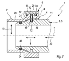
- FIGS. 1, 2 and 7 comprises a fluid line coupling 1, by means of which a fluid-carrying first component 2 can be mechanically and fluidically coupled to a fluid-carrying second component 3, a tube body 4, a nozzle 5 and a securing clip 6.
- the tube body 4 is integrally formed on the first in the examples shown here Part 2 formed. In principle, however, the tubular body 4 can also be a separate component which can be attached to the first component 2 in a suitable manner.
- the nozzle 5 is integrally formed on the second component 3 in the embodiment shown here. Basically, however, an embodiment is conceivable in which the nozzle 5 is a separate component, which may be attached to the second component 3 in a suitable manner. In any case, however, the securing clip 6 is a separate component.
- the tubular body 4 has a longitudinal central axis 7 which defines an axial direction 8 extending parallel to the longitudinal central axis 7.
- the nozzle 5 is coaxial in the tubular body 4 can be inserted and in the Figures 1 and 2 shown in the inserted state.
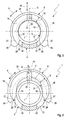
- the securing clip 6 is arranged on the outside of the tubular body 4 and surrounds the tubular body 4 in a in the FIGS. 3 to 6 indicated circumferential direction 9 over more than 180 °, for example about 270 °.
- the securing clip 6 is with respect to the tubular body 4 in a radial direction 10 between an in Fig. 5 shown securing position and a in Fig. 6 adjustable shown Entellesswolf. In the securing position according to Fig.
- the inserted into the pipe body 4 connecting piece 5 is secured by means of securing clip 6 on the tubular body 4, so that the nozzle 5 can not be pulled out of the tube body 4 without destroying the nozzle 5 and / or the securing clip 6 and / or the tubular body 4 is.
- the nozzle 5 is easily pulled out of the tubular body 4 in the armed position.
- the nozzle 5 has on its radially outer side outer 11 a securing groove 12 which extends in the circumferential direction 9.
- the tubular body 4 has a securing slot 13, which likewise extends in the circumferential direction 9 and which is aligned radially with respect to the securing groove 12 when the nozzle 5 is inserted into the tubular body 4.
- the securing clip 6 has on its radially inner side 14 a radially inwardly projecting securing web 15, which also extends in the circumferential direction 9. In the securing position, the securing web 15 extends through the securing slot 13 and also engages radially in the securing groove 12.
- the securing web 15 has a radially measured web height 18, which is reduced in web end sections 19 which extend beyond the 90 ° regions, or decreases in the direction of a web end 20.
- the securing web 15 in the respective web end portion 19 has a bevelled web end 20, which has a single, rectilinear region.
- the respective web end 20 is chamfered in two stages.
- the securing web 15 in the armed position according to Fig. 6 can no longer engage in the securing groove 12 of the nozzle 5.
- the securing web 15 then protrude only slightly over the securing slot 13, which in Fig. 6 is indicated on the right, or no longer protrude beyond the securing slot 13, which in Fig. 6 is shown on the left.
- the nozzle 5 on its outer side 11 have an extending in the circumferential direction 9 Ein 1500kontur 21, which is designed here as a cone, which tapers in a plug-in direction 22, in which the nozzle 5 in the tubular body 4, tapers.
- the securing clip 6 is designed to be radially resilient, which can be achieved, for example, by an appropriate choice of material. Additionally or alternatively, with reference to FIGS FIGS. 3 and 4 be explained in more detail measures to improve or to provide the desired radial elasticity of the securing clip 6 be realized.
- the securing clip 6 is expediently configured so resiliently that the nozzle 5 in the securing position Adjusted securing clip 6 in the tubular body 4 can be inserted.
- the Ein 1500kontur 21 meets axially on the radially inwardly projecting securing web 15 and causes a radially outwardly oriented displacement of the securing web 15, which then takes place against a spring force of the securing clip 6.
- the securing groove 12 is aligned with the securing web 15, whereby the securing web 15 can automatically engage in the securing groove 12.
- the securing web 15 is driven by the spring force of the securing clip 6 radially inwardly.
- the securing web 15 may have at least one web interruption 23 in the circumferential direction 9. Additionally or alternatively, the securing web 15 according to Fig. 4 have at least one radial web slot 24. While such a web interruption 23 extends over the entire radial height 18 of the securing web 15, the respective, radially inwardly open web slot 24 is dimensioned smaller in the radial direction than the radial height 18 of the securing web 15. In the example of Fig. 3 a single web interruption 23 is positioned symmetrically to the longitudinal center plane 16. In Fig.
- a plurality of web interruptions 23 and also a plurality of web slots 24 are provided, which may be distributed symmetrically symmetrical to the longitudinal center plane 16 in the circumferential direction 9.
- the respective web interruption 23 or the respective web slot 24 displaces the force flow paths oriented in the securing web 15 in the circumferential direction 9 radially outward into a band-shaped base body 25 of the securing clip 6. This improves the radial spring elasticity of the securing clip 6.
- the tubular body 4 on its radially outer side 26 have two Ausrastkerben 27, each extending axially, ie parallel to the longitudinal central axis 7.
- the Ausrastkerben 27 are on the outer side 26 of the tubular body 4 positioned so that in the armed position of the securing clip 6 each have a circumferential end 28 of the securing clip 6 can engage radially in each one of the Ausrastkerben 27, which in Fig. 6 is shown.
- the securing clip 6 is stably positioned in the armed position on the tubular body 4, whereby it is particularly easy to disassemble the fluid line coupling 1 manually or to uncouple the two components 2, 3 from each other.
- the securing slot 13 has a slot interruption 29, which is arranged substantially centrally between circumferential ends 30 of the securing slot 13, that is to say is likewise arranged centrally with respect to the longitudinal center plane 16.
- the securing web 15 now has complementary to the slot interruption 29 a web interruption 31, which is accordingly arranged centrally between circumferential ends 28 of the securing clip 6.
- the slot interruption 29 which forms an axial web on the tube body 4, radially into the web interruption 31, whereby a rotation between the securing clip 6 and the tubular body 4 is formed.
- the tube body 2 may have on its outside 26 at least one guide groove 32 which extends in the circumferential direction 9.
- the securing bracket 6 has on its inner side 14 complementary to at least one radially inwardly projecting guide web 33. At least in the securing position, the respective guide web 33 engages radially into the associated guide groove 32.
- FIGS. 1, 2 and 7 are each two mutually parallel guide grooves 32 formed on the tubular body 4, while complementary to the securing bracket 6, two mutually parallel guide webs 33 are present.
- At least one radial seal 34 extending in the circumferential direction 9 can be provided, which can be realized, for example, with the aid of an O-ring.
- the radial seal 34 is positioned between an inner side 35 of the tubular body 4 facing the neck 5 and the outer side 11 of the neck 5 in order to seal the fluid-carrying interior of the neck 5 and tubular body 4 with respect to an environment of the fluid line coupling 1.
- the tubular body 4 has axially adjacent to the radial seal 34 in the circumferential direction 9 in addition to the securing slot 13 provided positioning slot 36.
- the securing bracket 6 has on its inner side 14 in addition to the securing web 15 extending in the circumferential direction 9 Positioniersteg 37, the protrudes radially inward. In the securing position, the positioning web 37 extends radially through the positioning slot 36 and protrudes radially beyond the inner side 35 of the tubular body 4 so far that it forms an axial stop 38 for the radial seal 34.
- annular step 40 is formed on the inside of the tubular body 2, on which the radial seal 34 can likewise be supported axially as well as radially.
- the positioning slot 36 extends parallel to the securing slot 13.
- the positioning bar 37 extends parallel to the securing bar 15.
- Fig. 7 a variant of in Fig. 1 shown embodiment, which is also equipped with a radial seal 34.
- a circumferentially closed circumferential groove 40 is formed on the nozzle 5, in which the radial seal 34 is inserted.
- the radial dimensioning of the securing web 15 may preferably be selected so that the radial seal 34 does not come into contact with the securing web 15 when the connecting piece 5 is inserted into the tubular body 2.
- the outer cross section the radial seal 34 inserted into the circumferential groove 40 is smaller than the inner cross section of the securing web 15.
- the securing clip 6 may each have at its peripheral ends 28 a gripping element 39 with the aid of which a manual adjustment of the securing clip 6 is simplified.
- the respective grip element 39 forms a radial thickening of the circumferential end 28.
- the respective grip element 39 is formed integrally on the securing clip 6.
- the securing web 15 and the securing slot 13 extend in the circumferential direction 9 each less than 360 °, namely, for example, about 270 °.
- the securing groove 12 extends according to the Figures 1 and 2 the circumferential direction 9 over 360 °, ie completely circumferential in the circumferential direction 9.
- the nozzle 5 can be inserted into the tubular body 4 in each rotational position.
- the fluid line coupling 1 is an air line coupling of a fresh air system, with the aid of which combustion chambers of an internal combustion engine, which may be arranged in particular in a motor vehicle, fresh air is supplied.
- Such an air line coupling 1 then serves for mechanical and fluid coupling of an air-guiding first component 2 with an air-guiding second component 3.
- the first component 2 may be, for example, a low-pressure air line of a fresh-air system of a supercharged internal combustion engine, while the second component 3 is a compressor inlet of a supercharger the fresh air system arranged charging device may be.
- the first component 2 can also be a high-pressure air line of a fresh air system of a supercharged internal combustion engine, while then the second component 3 is a compressor outlet of a charging device arranged in the fresh air system can be.
- the second component 3 may be formed by a compressor inlet or by a compressor outlet of a compressor of an exhaust gas turbocharger, which is equipped with the nozzle 5.
- the first component 2 can thus be in particular a fresh air line of a fresh air system of an internal combustion engine having at least at one of its ends such a tubular body 4, for example, to connect the fresh air line to the aforementioned compressor inlet or to the aforementioned compressor outlet easy.
Abstract
Die vorliegende Erfindung betrifft eine Fluidleitungskupplung (1) zum mechanischen und fluidischen Kuppeln eines fluidführenden ersten Bauteils (2) mit einem fluidführenden zweiten Bauteil (3), mit einem Rohrkörper (4), den das erste Bauteil (2) aufweist oder der am ersten Bauteil (2) anbringbar ist, mit einem koaxial in den Rohrkörper (4) einsteckbaren Stutzen (5), den das zweite Bauteil (3) aufweist oder der am zweiten Bauteil (3) anbringbar ist. Die einfache Handhabung ergibt sich mit einer Sicherungsklammer (6), die außen am Rohrkörper (4) angeordnet ist, die den Rohrkörper (4) in einer Umfangsrichtung (9) über mehr als 180° umschließt und die zwischen einer Sicherungsstellung, in welcher der in den Rohrkörper (4) eingesteckte Stutzen (5) nicht aus dem Rohrkörper (4) herausziehbar ist, und einer Entsicherungsstellung, in welcher der in den Rohrkörper (4) eingesteckte Stutzen (5) aus dem Rohrkörper (4) herausziehbar ist, relativ zum Rohrkörper (4) radial verstellbar ist, wobei der Stutzen (5) an seiner Außenseite (11) eine Sicherungsnut (12) aufweist, die sich in der Umfangsrichtung (9) erstreckt, wobei der Rohrkörper (4) einen Sicherungsschlitz (13) aufweist, der sich in der Umfangsrichtung (9) erstreckt, wobei die Sicherungsklammer (6) an ihrer Innenseite (14) einen radial nach innen abstehenden Sicherungssteg (15) aufweist, der sich in der Umfangsrichtung (9) erstreckt, der in der Sicherungsstellung durch den Sicherungsschlitz (13) hindurch radial in die Sicherungsnut (12) eingreift und der in der Entsicherungsstellung von der in die Sicherungsnut (12) frei kommt.The present invention relates to a fluid line coupling (1) for mechanically and fluidically coupling a fluid-carrying first component (2) with a fluid-carrying second component (3), with a tubular body (4) having the first component (2) or on the first component (2) is attachable, with a coaxially into the tubular body (4) insertable socket (5), which has the second component (3) or which is attachable to the second component (3). The ease of handling results with a securing clip (6) which is arranged on the outside of the tubular body (4), which surrounds the tubular body (4) in a circumferential direction (9) over more than 180 ° and between a securing position, in which the in the pipe body (4) inserted nozzle (5) is not pulled out of the tubular body (4), and a Entsicherungsstellung in which in the pipe body (4) inserted nozzle (5) from the tubular body (4) is pulled out, relative to the tubular body (4) is radially adjustable, wherein the nozzle (5) on its outer side (11) has a securing groove (12) which extends in the circumferential direction (9), wherein the tubular body (4) has a securing slot (13) extends in the circumferential direction (9), wherein the securing clip (6) on its inner side (14) has a radially inwardly projecting securing web (15) which extends in the circumferential direction (9), which in the securing position by the S slot (13) radially engages in the securing groove (12) and in the Entsicherungsstellung of the in the securing groove (12) comes free.
Description
Die vorliegende Erfindung betrifft eine Fluidleitungskupplung zum mechanischen und fluidischen Kuppeln eines fluidführenden ersten Bauteils mit einem fluidführenden zweiten Bauteil. Die Erfindung betrifft außerdem eine Aufladeeinrichtung, die mittels einer derartigen Fluidleitungskupplung an eine Frischluftleitung einer Frischluftanlage einer Brennkraftmaschine anschließbar ist. Schließlich betrifft die vorliegende Erfindung noch eine Frischluftleitung einer Frischluftanlage einer Brennkraftmaschine, die mittels einer derartigen Fluidleitungskupplung an eine andere fluidführende Komponente anschließbar ist.The present invention relates to a fluid line coupling for the mechanical and fluidic coupling of a fluid-carrying first component with a fluid-carrying second component. The invention also relates to a charging device which can be connected by means of such a fluid line coupling to a fresh air line of a fresh air system of an internal combustion engine. Finally, the present invention also relates to a fresh air line of a fresh air system of an internal combustion engine, which can be connected by means of such a fluid line coupling to another fluid-carrying component.
In vielen Bereichen der Technik ist es erforderlich, ein erstes fluidführendes Bauteil mit einem zweiten fluidführenden Bauteil fluidisch und mechanisch zu verbinden. Um dies einfach realisieren zu können, kann eine Fluidleitungskupplung verwendet werden. Insbesondere bei Brennkraftmaschinen, vorzugsweise in Kraftfahrzeugen, können derartige Fluidleitungskupplungen zur Anwendung kommen, beispielsweise um fluidführende Leitungen miteinander oder an Komponenten anschließen zu können, denen ein Fluid zugeführt werden muss oder von denen ein Fluid abgeführt werden muss. Denkbar sind derartige Fluidleitungskupplungen beispielsweise innerhalb eines Kühlkreises. Besonders vorteilhaft lassen sich derartige Fluidleitungskupplungen jedoch im Bereich einer Frischluftanlage nutzen. Besonders geeignet ist eine derartige Fluidleitungskupplung im Bereich einer Ladeeinrichtung, insbesondere eines Abgasturboladers, um eine Frischluftleitung an einen Einlass der Ladeeinrichtung und/oder um eine Frischluftleitung an einen Auslass der Ladeeinrichtung anzuschließen.In many areas of technology, it is necessary to fluidly and mechanically connect a first fluid-carrying component with a second fluid-carrying component. To realize this easily, a fluid line coupling can be used. In particular, in internal combustion engines, preferably in motor vehicles, such fluid line couplings can be used, for example, to be able to connect fluid-carrying lines with each other or to components to which a fluid must be supplied or from which a fluid must be removed. Conceivable are such fluid line couplings, for example, within a cooling circuit. However, such fluid line couplings can be used particularly advantageously in the area of a fresh air system. Such a fluid line coupling in the region of a charging device, in particular an exhaust gas turbocharger, is particularly suitable for connecting a fresh air line to an inlet of the charging device and / or to a fresh air line to an outlet of the charging device.
Damit eine derartige Fluidleitungskupplung im Rahmen einer Serienmontage verwendbar ist, muss sie vergleichsweise einfach handhabbar sein. Außerdem sollte sie auch für schlecht zugängliche oder schlecht einsehbare Bereiche verwendbar sein, so dass sie insbesondere blind und/oder werkzeuglos montierbar ist. Des Weiteren sollte eine derartige Fluidleitungskupplung wieder vergleichsweise leicht demontierbar sein bzw. trennbar sein, ebenfalls vorzugsweise blind und/oder werkzeuglos.For such a fluid line coupling to be used in a series assembly, it must be comparatively easy to handle. In addition, it should also be usable for poorly accessible or poorly visible areas, so that it is particularly blind and / or tool-mountable. Furthermore, such a fluid line coupling should again be comparatively easy to disassemble or be separable, likewise preferably blind and / or tool-free.
Die vorliegende Erfindung beschäftigt sich mit dem Problem, für eine derartige Fluidleitungskupplung eine verbesserte Ausführungsform anzugeben, die sich durch eine hohe Zuverlässigkeit, durch eine einfache Handhabung und durch eine preiswerte Herstellbarkeit auszeichnet.The present invention is concerned with the problem of providing for such a fluid line coupling an improved embodiment, which is characterized by a high reliability, by a simple handling and by an inexpensive manufacturability.
Dieses Problem wird erfindungsgemäß durch den Gegenstand des unabhängigen Anspruchs gelöst. Vorteilhafte Ausführungsformen sind Gegenstand der abhängigen Ansprüche.This problem is solved according to the invention by the subject matter of the independent claim. Advantageous embodiments are the subject of the dependent claims.
Die Erfindung beruht auf dem allgemeinen Gedanken, die Fluidleitungskupplung mit einem Rohrkörper, einem damit steckbaren Stutzen und mit einer Sicherungsklammer auszustatten, wobei der Stutzen in den Rohrkörper einsteckbar ist, während die Sicherungsklammer außen am Rohrkörper angeordnet und zwischen einer Sicherungsstellung und einer Entsicherungsstellung relativ zum Rohrkörper radial verstellbar ist. Dabei bilden Stutzen, Rohrkörper und Sicherungsklammer drei separate Bauteile. In der Entsicherungsstellung ist der in den Rohrkörper eingesteckte Stutzen aus dem Rohrkörper herausziehbar. In der Sicherungsstellung ist der in den Rohrkörper eingesteckte Stutzen dagegen nicht aus dem Rohrkörper herausziehbar. Dabei ist klar, dass zum Herausziehen nur übliche Zugkräfte aufgebracht werden sollen, die unterhalb einer Versagensgrenze der beteiligten Bauteile liegen. Mit anderen Worten, in der Entsicherungsstellung lässt sich der Stutzen zerstörungsfrei aus dem Rohrkörper herausziehen, während dies in der Sicherungsstellung nicht möglich ist. Unter Aufwendung überhöhter Missbrauchskräfte führt ein Herausziehen des Stutzens aus dem Rohrkörper in der Sicherungsstellung der Sicherungsklammer zwangsläufig zu einer Zerstörung oder Beschädigung zumindest eines der drei Bauteile. Während sich der Stutzen nur in der Entsicherungsstellung der Sicherungsklammer zerstörungsfrei aus dem Rohrkörper herausziehen lässt, kann gemäß einer bevorzugten Ausführungsform vorgesehen sein, dass sich der Stutzen immer in den Rohrkörper einstecken lässt, unabhängig davon, ob die Sicherungsklammer ihre Sicherungsstellung oder ihre Entsicherungsstellung einnimmt. Bei in die Sicherungsstellung verstellter Sicherungsklammer kann das Einstecken des Stutzens in den Rohrkörper ein radiales Verdrängen der Sicherungsklammer relativ zum Rohrkörper bewirken, was entgegen der Federkräfte der Sicherungsklammer erfolgt, so dass die Sicherungsklammer quasi elastisch gespannt wird. Erreicht dann der Stutzen die vorgesehene Eindringposition im Rohrkörper, kann die Sicherungsklammer angetrieben durch ihre Rückstellfederkraft radial zurückfedern und sich selbsttätig in ihre Sicherungsstellung bewegen. Hierdurch kann die Montage erheblich vereinfacht werden.The invention is based on the general idea to equip the fluid line coupling with a tubular body, a plug-in nozzle and with a securing clip, wherein the nozzle is inserted into the tubular body, while the securing clip disposed outside of the tubular body and between a securing position and a Entsicherungsstellung relative to the tubular body is radially adjustable. The nozzle, pipe body and securing clip form three separate components. In the armed position, the pipe socket inserted into the pipe body can be pulled out of the pipe body. In the safety position, however, the pipe plug inserted into the pipe body can not be pulled out of the pipe body. It is clear that only conventional tensile forces are to be applied to pull out, which are below a failure limit of the components involved. In other words, in the armed position can the nipple destructively pull out of the tubular body, while this is not possible in the securing position. By using excessive abuse forces pulling out the nozzle from the tubular body in the securing position of the securing clip inevitably leads to destruction or damage to at least one of the three components. While the nozzle can be pulled out of the tubular body nondestructively only in the armed position of the securing clip, according to a preferred embodiment it can be provided that the nozzle can always be inserted into the tubular body, regardless of whether the securing clip assumes its securing position or its releasing position. When adjusted in the securing position securing clip, the insertion of the nozzle into the tubular body can cause a radial displacement of the securing clip relative to the tubular body, which takes place against the spring forces of the securing clip, so that the securing clip is stretched quasi elastic. If the nozzle then reaches the intended penetration position in the tubular body, the safety clip, driven by its return spring force, can spring back radially and automatically move into its securing position. As a result, the assembly can be considerably simplified.
Im Einzelnen ist vorgesehen, dass der Rohrkörper am ersten Bauteil anbringbar ist oder am ersten Bauteil vorhanden ist, während der Stutzen am zweiten Bauteil anbringbar ist oder daran vorhanden ist. Die Sicherungsklammer umschließt den Rohrkörper in einer Umfangsrichtung über mehr als 180°, so dass sie in der Sicherungsstellung selbstsichernd am Rohrkörper festgelegt ist bzw. damit verklammert ist. Zur Realisierung der Sicherungsstellung und der Entsicherungsstellung weist der Stutzen an seiner radial außen liegenden Außenseite eine Sicherungsnut auf, die sich in der Umfangsrichtung erstreckt. Der Rohrkörper ist mit einem Sicherungsschlitz ausgestattet, der sich in der Umfangsrichtung erstreckt und der bei in den Rohrkörper eingestecktem Stutzen radial zur Sicherungsnut des Stutzens fluchtet. Während die Sicherungsnut eine zylindrische Wand des Stutzens in der Regel nicht durchdringt, durchsetzt der Sicherungsschlitz eine zylindrische Wand des Rohrkörpers radial. Die Sicherungsklammer besitzt nun an ihrer radial innen liegenden Innenseite einen radial nach innen abstehenden Sicherungssteg, der sich in der Umfangsrichtung erstreckt und der in der Sicherungsstellung durch den Sicherungsschlitz hindurch radial in die Sicherungsnut eingreift. Zum Überführen der Sicherungsklammer von ihrer Sicherungsstellung in ihre Entsicherungsstellung wird sie relativ zum Rohrkörper radial nach außen verstellt, so weit, dass der Sicherungssteg in der Entsicherungsstellung nicht mehr radial in die Sicherungsnut eingreift. Durch den radialen Eingriff des Sicherungsstegs in die Sicherungsnut ergibt sich ein axialer Formschluss, der den Stutzen an der Sicherungsklammer axial fixiert. Durch den Eingriff des Sicherungsstegs in den Sicherungsschlitz ergibt sich außerdem ein axialer Formschluss, der die Sicherungsklammer am Rohrkörper axial fixiert, so dass letztlich über die Sicherungsklammer auch der Stutzen am Rohrkörper formschlüssig in der Axialrichtung fixiert ist. Durch Herausziehen des Sicherungsstegs aus der Sicherungsnut wird nur der Stutzen relativ zur Sicherungsklammer und somit relativ zum Rohrkörper freigegeben, während die Sicherungsklammer am Rohrkörper zumindest in der Axialrichtung fixiert bleibt. Die hier vorgestellte Fluidleitungskupplung lässt sich einfach handhaben, da lediglich die Sicherungsklammer radial gegenüber dem Rohrkörper verstellt werden muss.Specifically, it is provided that the tubular body is attachable to the first component or is present on the first component, while the nozzle is attachable to the second component or is present there. The securing clip surrounds the tubular body in a circumferential direction over more than 180 °, so that it is fixed in the securing position self-locking on the tubular body or clamped with it. To realize the securing position and the unlocking position, the connecting piece has a securing groove on its radially outer side, which extends in the circumferential direction. The tubular body is provided with a securing slot which extends in the circumferential direction and the radially inserted into the tubular body connecting piece to the securing groove of the neck is aligned. While the securing groove usually does not penetrate a cylindrical wall of the connecting piece, the securing slot radially penetrates a cylindrical wall of the tubular body. The securing bracket now has on its radially inner side inside a radially inwardly projecting securing web which extends in the circumferential direction and which engages in the securing position through the securing slot radially into the securing groove. For transferring the securing clip from its securing position into its unlocking position, it is adjusted radially outward relative to the tubular body, so far that the securing web no longer engages radially in the securing groove in the unlocking position. The radial engagement of the securing web in the securing groove results in an axial positive locking, which axially fixes the neck on the securing clip. Through the engagement of the securing web in the securing slot also results in an axial positive locking, which axially fixes the securing clip on the tubular body, so that ultimately on the securing clip and the nozzle on the tubular body is positively fixed in the axial direction. By pulling the securing web out of the securing groove, only the connecting piece is released relative to the securing clip and thus relative to the tubular body, while the securing clip remains fixed on the tubular body at least in the axial direction. The presented here fluid line coupling is easy to handle, since only the securing clip must be adjusted radially relative to the pipe body.
Entsprechend einer vorteilhaften Ausführungsform kann der Sicherungssteg auch in der Entsicherungsstellung im Sicherungsschlitz angeordnet sein. Auf diese Weise kann auch in der Entsicherungsstellung eine vorbestimmte axiale Relativlage zwischen Sicherungsklammer und Rohrkörper beibehalten werden, was die Montage vereinfacht. Somit verbleibt die Sicherungsklammer auch in der Entsicherungsstellung am Rohrkörper.According to an advantageous embodiment, the securing web can also be arranged in the unlocking position in the securing slot. In this way, a predetermined axial relative position between securing clip and tubular body can be maintained even in the armed position, which simplifies the assembly. Thus, the securing clip also remains in the armed position on the tubular body.
Bei einer anderen Ausführungsform kann sich der Sicherungssteg ausgehend von einer Längsmittelebene in der Umfangsrichtung beidseitig über mehr als 90° erstrecken, wobei eine radial gemessene Steghöhe in Stegendabschnitten, die über die 90° hinausgehen, reduziert ist oder in Richtung eines Stegendes abnimmt. Durch diese Bauweise wird erreicht, dass der Sicherungssteg in der Entsicherungsstellung im Bereich seiner Stegendabschnitte, die von der Längsmittelebene den über die 90° hinausgehenden Bereich des Sicherungsstegs bilden, radial nicht mehr bis in die Sicherungsnut vorstehen kann und insbesondere innerhalb des Sicherungsschlitzes verbleibt. Auf diese Weise ist gewährleistet, dass der Stutzen in der Entsicherungsstellung bei einer einfachen Geometrie der Sicherungsklammer aus dem Rohrkörper herausziehbar ist. Eine abnehmende Steghöhe kann beispielsweise dadurch erreicht werden, dass im Bereich der Stegendabschnitte ein Innenradius an einen radial innen liegenden Innenrand des Sicherungsstegs im Bereich der Stegendabschnitte größer ist als in den Bereichen bis zu den 90° ausgehend von der Längsmittelebene. Ebenso ist es möglich, im Bereich der Stegendabschnitte einen geradlinigen Verlauf für den Steginnenrand vorzusehen und diesen insbesondere so zu orientieren, dass sich der jeweilige Innenrand in der Entsicherungsstellung parallel zur radialen Verstellrichtung der Sicherungsklammer erstreckt.In another embodiment, the securing web, starting from a longitudinal center plane in the circumferential direction on both sides extend over more than 90 °, wherein a radially measured web height is reduced in web end sections that extend beyond 90 °, or decreases in the direction of a web end. This construction ensures that the securing web in the unlocking position in the region of its web end sections, which form the region of the securing web extending beyond the 90 ° from the longitudinal center plane, can no longer protrude radially into the securing groove and in particular remain within the securing slot. In this way, it is ensured that the nozzle in the unlocked position can be pulled out of the tubular body with a simple geometry of the securing clip. A decreasing web height can be achieved, for example, in that in the area of the web end sections an inner radius is greater at a radially inner inner edge of the securing web in the area of the web end sections than in the areas up to the 90 ° starting from the longitudinal center plane. It is also possible to provide a linear course for the web inner edge in the region of the web end sections and to orient it in particular in such a way that the respective inner edge extends parallel to the radial adjustment direction of the securing clip in the unlocking position.
Entsprechend einer anderen vorteilhaften Ausführungsform kann der Stutzen an seiner Außenseite eine sich in der Umfangsrichtung erstreckende Einführkontur aufweisen, die beispielsweise als Fase oder Einführschräge oder dergleichen ausgestaltet sein kann. Die Sicherungsklammer ist zweckmäßig radial federelastisch ausgestaltet, derart, dass der Stutzen bei in die Sicherungsstellung verstellter Sicherungsklammer in den Rohrkörper einsteckbar ist. Mit anderen Worten, die hier vorgestellte Fluidleitungskupplung ermöglicht ein Einstecken des Stutzens in den Rohrkörper bei in die Sicherungsstellung verstellter Sicherungsklammer, wodurch gleichzeitig bei Erreichen der vorgesehenen Einsteckposition automatisch die Sicherung des Stutzens im Rohrkörper erfolgt. Im Einzelnen kann der Sicherungssteg beim Einstecken des Stutzens in den Rohrkörper vor Erreichen einer vorbestimmten Einstecktiefe durch die Einführkontur des Stutzens radial nach außen verdrängt werden, so dass er bei Erreichen der vorbestimmten Einstecktiefe selbsttätig in die Sicherungsnut einrastet. Erreicht wird dies durch eine geeignete Abstimmung der Einführkontur auf den Sicherungssteg in Verbindung mit der Federelastizität der Sicherungsklammer, so dass der Stutzen beim Einstecken die Sicherungsklammer soweit aufweiten kann, dass er axial am Sicherungssteg vorbeiführbar ist, bis dieser aufgrund der Federkraft der Sicherungsklammer selbsttätig in die Sicherungsnut eingreift. Diese Maßnahme führt zu einer extremen Vereinfachung der Montage.According to another advantageous embodiment of the neck may have on its outer side extending in the circumferential direction Einführkontur, which may be configured for example as a chamfer or insertion bevel or the like. The securing clip is expedient configured radially resiliently, such that the neck is inserted in the pipe body in the securing position adjusted securing clip. In other words, the fluid line coupling presented here allows insertion of the nozzle into the tubular body in the securing position adjusted securing clip, thereby simultaneously reaching the intended insertion position automatically securing the nozzle in the tubular body is done. Specifically, the securing web can be displaced radially outwardly upon insertion of the nozzle into the pipe body before reaching a predetermined insertion depth through the Einführkontur of the nozzle, so that it automatically engages on reaching the predetermined insertion depth in the securing groove. This is achieved by a suitable vote of the Einführkontur on the securing bar in conjunction with the spring elasticity of the securing clip, so that the socket when inserting the securing clip can widen so far that it can be axially fed past the securing bar until it automatically due to the spring force of the securing clip in the Locking groove engages. This measure leads to an extreme simplification of the assembly.
Bei einer anderen Ausführungsform kann der Rohrkörper an seiner Außenseite zwei Ausrastkerben aufweisen, die sich axial erstrecken und in die je ein Umfangsende der Sicherungsklammer in deren Entsicherungsstellung radial eingreift. Beim Überführen der Sicherungsklammer von ihrer Sicherungsstellung in ihre Entsicherungsstellung wird diese elastisch aufgeweitet, so dass die Umfangsenden vorgespannt in die Ausrastkerben radial eingreifen und dadurch eine Positionierung der Sicherungsklammer relativ zum Rohrkörper bewirken. Mit anderen Worten, mit Hilfe der Ausrastkerben kann die Sicherungsklammer selbsttätig in der Entsicherungsstellung am Rohrkörper gehalten sein, was ebenfalls die Montage sowie die Demontage erleichtert. Die Verrastung zwischen den Umfangsenden und den Ausrastkerben kann durch leichten Druck auf die Sicherungsklammer überwunden werden, so dass die Sicherungsklammer angetrieben durch ihre Federelastizität selbsttätig in ihre Sicherungsstellung zurück schnappt.In another embodiment, the tubular body may have on its outer side two Ausrastkerben extending axially and engages in each of which a circumferential end of the securing clip in its Entsicherungsstellung radially. When transferring the securing clip from its securing position into its releasing position, it is elastically expanded, so that the circumferential ends engage radially in the disengaging notches and thereby bring about a positioning of the securing clip relative to the tubular body. In other words, with the help of Ausrastkerben the securing clip can be automatically held in the armed position on the tubular body, which also facilitates the assembly and disassembly. The latching between the circumferential ends and the Ausrastkerben can be overcome by slight pressure on the securing clip, so that the securing clip driven by its spring elasticity automatically snaps back into its securing position.
Bei einer anderen vorteilhaften Ausführungsform kann der Sicherungssteg in der Umfangsrichtung wenigstens eine Stegunterbrechung oder wenigstens einen radialen Stegschlitz aufweisen. Hierdurch kann die gewünschte radiale Elastizität der Sicherungsklammer eingestellt werden. Während eine Stegunterbrechung sich über die gesamte radiale Höhe des Sicherungsstegs erstreckt, unterbricht ein Stegschlitz den Sicherungssteg nur über einen Teil seiner gesamten radialen Höhe.In another advantageous embodiment, the securing web can have at least one web interruption or at least one radial web slot in the circumferential direction. This allows the desired radial elasticity the securing clip are adjusted. While a web interruption extends over the entire radial height of the securing web, a web slot interrupts the securing web only over part of its entire radial height.
Zweckmäßig können mehrere derartige Stegunterbrechungen bzw. Stegschlitze vorgesehen sein, die in der Umfangsrichtung, vorzugsweise symmetrisch, verteilt sind. Alternativ dazu kann auch vorgesehen sein, dass nur eine einzige Stegunterbrechung bzw. nur ein einziger Stegschlitz vorgesehen ist, die bzw. der sich dann im Bereich der Längsmittelebene der Sicherungsklammer bzw. des Sicherungsstegs befindet.Suitably, a plurality of such web interruptions or web slots may be provided which are distributed in the circumferential direction, preferably symmetrically. Alternatively, it can also be provided that only a single web interruption or only a single web slot is provided, which is then in the region of the longitudinal center plane of the securing clip or the securing web.
Bei einer anderen vorteilhaften Ausführungsform kann der Sicherungsschlitz eine Schlitzunterbrechung aufweisen, die mittig zwischen Umfangsenden des Sicherungsschlitzes angeordnet ist. Komplementär dazu kann dann der Sicherungssteg eine Stegunterbrechung aufweisen, derart, dass die Schlitzunterbrechung zur Ausbildung einer Verdrehsicherung zwischen Sicherungsklammer und Rohrkörper radial in die Stegunterbrechung eingreift. Durch die auf diese Weise realisierte Verdrehsicherung zwischen Sicherungsklammer und Rohrkörper lässt sich die Sicherungsklammer zuverlässig zwischen der Sicherungsstellung und der Entsicherungsstellung verstellen.In another advantageous embodiment, the securing slot can have a slot interruption, which is arranged centrally between circumferential ends of the securing slot. Complementarily, then, the securing web may have a web interruption, such that the slot interruption engages radially into the web interruption to form an anti-rotation between securing clip and tubular body. By realized in this way against rotation between securing clip and pipe body, the securing clip can be adjusted reliably between the securing position and the armed position.
Gemäß einer anderen vorteilhaften Ausführungsform kann der Rohrkörper an seiner Außenseite wenigstens eine Führungsnut aufweisen, die sich in der Umfangsrichtung erstreckt. Komplementär dazu kann die Sicherungsklammer an ihrer Innenseite wenigstens einen radial nach innen abstehenden Führungssteg aufweisen, der sich ebenfalls in der Umfangsrichtung erstreckt und der zumindest in der Sicherungsstellung in die zugehörige Führungsnut radial eingreift. Mit Hilfe der Führungsnut und des darin eingreifenden Führungsstegs wird ein zusätzlicher axialer Formschluss zwischen Sicherungsklammer und Rohrkörper realisiert, der die axiale Fixierung zwischen Sicherungsklammer und Rohrkörper verbessert.According to another advantageous embodiment, the tubular body may have on its outer side at least one guide groove which extends in the circumferential direction. Complementarily, the securing clip on its inside have at least one radially inwardly projecting guide web, which also extends in the circumferential direction and engages radially at least in the securing position in the associated guide groove. With the help of the guide groove and the engaging therein guide web is an additional realized axial positive connection between securing clip and tubular body, which improves the axial fixation between securing clip and tubular body.
Bei einer anderen vorteilhaften Ausführungsform kann wenigstens eine sich in der Umfangsrichtung geschlossen erstreckende Radialdichtung zwischen einer Innenseite des Rohrkörpers und der Außenseite des Stutzens vorgesehen sein. Hierdurch kann die Fluidleitungskupplung nach außen gegen das zu leitende Fluid abgedichtet werden. Eine derartige Radialdichtung kann dabei in eine Umfangsnut eingelegt sein, die grundsätzlich an der Innenseite des Rohrkörpers, bevorzugt jedoch an der Außenseite des Stutzens angeordnet sein kann.In another advantageous embodiment, at least one radially extending in the circumferential direction radially extending seal between an inner side of the tubular body and the outside of the nozzle may be provided. In this way, the fluid line coupling can be sealed to the outside against the fluid to be conducted. Such a radial seal can be inserted into a circumferential groove, which can in principle be arranged on the inside of the tubular body, but preferably on the outside of the neck.
Entsprechend einer vorteilhaften Weiterbildung kann der Rohrkörper axial benachbart zu einer solchen Radialdichtung einen sich in der Umfangsrichtung erstreckenden Positionierschlitz aufweisen. Die Sicherungsklammer kann nun an ihrer Innenseite axial beabstandet zum Sicherungssteg einen radial nach innen abstehenden Positioniersteg aufweisen, der sich ebenfalls in der Umfangsrichtung erstreckt und der in der Sicherungsstellung durch den Positionierschlitz hindurch radial über die Innenseite des Rohrkörpers vorsteht und einen Axialanschlag für die Radialdichtung bildet. Durch den Axialanschlag ist die Radialdichtung in der Axialrichtung relativ zum Rohrkörper positioniert. Gleichzeitig bewirkt der in den Positionierschlitz eingreifende Positioniersteg einen axialen Formschluss zur axialen Fixierung der Sicherungsklammer am Rohrkörper.According to an advantageous development of the tubular body axially adjacent to such a radial seal may have a extending in the circumferential direction positioning slot. The securing clip can now have on its inside axially spaced from the securing web a radially inwardly projecting positioning web, which also extends in the circumferential direction and the projecting in the securing position through the positioning radially over the inside of the tubular body and forms an axial stop for the radial seal. Due to the axial stop, the radial seal is positioned in the axial direction relative to the tubular body. At the same time, the positioning web engaging in the positioning slot effects an axial positive engagement for the axial fixing of the securing clip on the tubular body.
Bei einer anderen Ausführungsform kann die Sicherungsklammer an ihren Umfangsenden je ein Griffelement zum manuellen Verstellen der Sicherungsklammer in deren Entsicherungsstellung aufweisen. Mit Hilfe derartiger Griffelemente vereinfacht sich die Handhabung der Fluidleitungskupplung, beispielsweise um den Stutzen aus dem Rohrkörper herausziehen zu können. Ein derartiges Griffelement kann insbesondere integral an der Sicherungsklammer ausgeformt sein.In another embodiment, the securing clip may each have a handle element for manual adjustment of the securing clip in its armed position at its peripheral ends. With the help of such handle elements, the handling of the fluid line coupling, for example, simplified to be able to pull the nozzle out of the tube body. Such a grip element may in particular be integrally formed on the securing clip.
Bei einer anderen vorteilhaften Ausführungsform kann die Fluidleitungskupplung eine Luftleitungskupplung einer Frischluftanlage zum Zuführen von Frischluft zu Brennräumen einer Brennkraftmaschine, insbesondere eines Kraftfahrzeugs sein, und zum mechanischen und fluidischen Kuppeln eines luftführenden ersten Bauteils mit einem luftführenden zweiten Bauteil dienen. Bei einer aufgeladenen Brennkraftmaschine kann sich diese Fluidleitungskupplung auf der Niederdruckseite oder aber auf der Hochdruckseite befinden. Sie kann insbesondere dazu verwendet werden, eine Frischluftleitung einlassseitig oder auslassseitig an einen Verdichter eines Abgasturboladers anzuschließen.In another advantageous embodiment, the fluid line coupling may be an air line coupling of a fresh air system for supplying fresh air to combustion chambers of an internal combustion engine, in particular of a motor vehicle, and for mechanical and fluidic coupling of an air-conducting first component with an air-guiding second component. In a supercharged internal combustion engine, this fluid line coupling may be on the low pressure side or on the high pressure side. It can be used in particular to connect a fresh air line on the inlet side or outlet side to a compressor of an exhaust gas turbocharger.
Bei einer anderen vorteilhaften Ausführungsform können sich der Sicherungssteg und der Sicherungsschlitz in der Umfangsrichtung jeweils über weniger als 360° erstrecken, während sich die Sicherungsnut in der Umfangsrichtung über 360°, also vollständig geschlossen umlaufend, erstreckt. Hierdurch ist es möglich, den Sicherungsstutzen in jeder beliebigen Drehlage in den Rohrkörper einzustecken. Ferner ist es möglich, den in den Rohrkörper eingesteckten Stutzen in der Umfangsrichtung relativ zum Rohrkörper zu verdrehen. Sicherungssteg und Sicherungsschlitz erstrecken sich beispielsweise über etwa 270°. Auch die ggf. vorhandene Führungsnut und dazugehörige Führungssteg erstrecken sich ebenso wie der ggf. vorhandene Positionierschlitz und der zugehörige Positioniersteg über weniger als 360° in der Umfangsrichtung, beispielsweise ebenfalls etwa über 270°.In another advantageous embodiment, the securing web and the securing slot in the circumferential direction in each case extend over less than 360 °, while the securing groove in the circumferential direction over 360 °, so completely closed circumferentially extends. This makes it possible to insert the fuse in any rotational position in the pipe body. Furthermore, it is possible to rotate the nozzle inserted into the pipe body in the circumferential direction relative to the pipe body. Security bar and securing slot extend for example about 270 °. The optionally existing guide groove and associated guide bar extend as well as the possibly existing positioning slot and the associated positioning web over less than 360 ° in the circumferential direction, for example also about 270 °.
Bei einer anderen vorteilhaften Ausführungsform kann der Rohrkörper integral am ersten Bauteil ausgeformt sein. Zusätzlich oder alternativ kann vorgesehen sein, dass der Stutzen integral am zweiten Bauteil ausgeformt ist. Die integrale Bauweise reduziert die Anzahl zu verbauender Bauteile, was die Handhabung und die Montage erleichtert.In another advantageous embodiment, the tubular body can be formed integrally on the first component. Additionally or alternatively it can be provided that the nozzle is integrally formed on the second component. The integral Construction reduces the number of components to be installed, which facilitates handling and assembly.
Der Rohrkörper und die Sicherungsklammer können bevorzugt aus Kunststoff hergestellt sein, wobei hier grundsätzlich der gleiche Kunststoff verwendet werden kann. Der Stutzen kann dagegen aus Kunststoff oder aus Metall hergestellt sein. Sofern der Stutzen aus Kunststoff hergestellt ist, kann es sich hierbei bevorzugt um einen faserverstärkten Kunststoff handeln.The tubular body and the securing clip may preferably be made of plastic, in which case in principle the same plastic can be used. The nozzle, however, can be made of plastic or metal. If the nozzle is made of plastic, this may preferably be a fiber-reinforced plastic.
Entsprechend einer anderen vorteilhaften Ausführungsform kann das erste Bauteil eine Niederdruckluftleitung einer Frischluftanlage einer aufgeladenen Brennkraftmaschine sein, während das zweite Bauteil ein Verdichtereinlass einer in der Frischluftanlage angeordneten Ladeeinrichtung ist. Alternativ dazu kann das erste Bauteil eine Hochdruckluftleitung einer Frischluftanlage einer aufgeladenen Brennkraftmaschine sein, während das zweite Bauteil dann ein Verdichterauslass einer in der Frischluftanlage angeordneten Ladeeinrichtung ist.According to another advantageous embodiment, the first component may be a low-pressure air line of a fresh air system of a supercharged internal combustion engine, while the second component is a compressor inlet of a charging device arranged in the fresh air system. Alternatively, the first component may be a high-pressure air line of a fresh air system of a supercharged internal combustion engine, while the second component is then a compressor outlet of a charging device arranged in the fresh air system.
Eine erfindungsgemäße Ladeeinrichtung, bei der es sich insbesondere um einen Abgasturbolader handeln kann und die sich für eine Frischluftanlage einer Brennkraftmaschine eignet, ist mit einem Verdichtereinlass und mit einem Verdichterauslass ausgestattet, wobei der Verdichtereinlass und/oder der Verdichterauslass einen Stutzen einer Fluidleitungskupplung der vorstehend beschriebenen Art aufweist, so dass er mittels einer derartigen Fluidleitungskupplung an eine Niederdruckluftleitung bzw. an eine Hochdruckluftleitung anschließbar ist.A charging device according to the invention, which may in particular be an exhaust gas turbocharger and which is suitable for a fresh air system of an internal combustion engine, is equipped with a compressor inlet and with a compressor outlet, wherein the compressor inlet and / or the compressor outlet a nozzle of a fluid line coupling of the type described above so that it can be connected by means of such a fluid line coupling to a low pressure air line or to a high pressure air line.
Eine erfindungsgemäße Frischluftleitung einer Frischluftanlage einer Brennkraftmaschine weist an wenigstens einen ihrer Enden einen Rohrkörper einer Fluidleitungskupplung der vorstehend beschriebenen Art auf, so dass diese Frischluftleitung mittels einer derartigen Fluidleitungskupplung an eine andere Komponente der Brennkraftmaschine anschließbar ist.An inventive fresh air line of a fresh air system of an internal combustion engine has at least one of its ends a tubular body of a fluid line coupling of the type described above, so that these fresh air line can be connected by means of such a fluid line coupling to another component of the internal combustion engine.
Weitere wichtige Merkmale und Vorteile der Erfindung ergeben sich aus den Unteransprüchen, aus den Zeichnungen und aus der zugehörigen Figurenbeschreibung anhand der Zeichnungen.Other important features and advantages of the invention will become apparent from the dependent claims, from the drawings and from the associated figure description with reference to the drawings.
Es versteht sich, dass die vorstehend genannten und die nachstehend noch zu erläuternden Merkmale nicht nur in der jeweils angegebenen Kombination, sondern auch in anderen Kombinationen oder in Alleinstellung verwendbar sind, ohne den Rahmen der vorliegenden Erfindung zu verlassen.It is understood that the features mentioned above and those yet to be explained below can be used not only in the particular combination given, but also in other combinations or in isolation, without departing from the scope of the present invention.
Bevorzugte Ausführungsbeispiele der Erfindung sind in den Zeichnungen dargestellt und werden in der nachfolgenden Beschreibung näher erläutert, wobei sich gleiche Bezugszeichen auf gleiche oder ähnliche oder funktional gleiche Komponenten beziehen.Preferred embodiments of the invention are illustrated in the drawings and will be described in more detail in the following description, wherein like reference numerals refer to the same or similar or functionally identical components.
Es zeigen, jeweils schematisch,
- Fig. 1
- einen Längsschnitt durch eine Fluidleitungskupplung,
- Fig. 2
- einen Längsschnitt wie in
Fig. 1 , jedoch bei einer anderen Ausführungsform der Fluidleitungskupplung, - Fig. 3
- eine Axialansicht einer Sicherungsklammer der Fluidleitungskupplung,
- Fig. 4
- eine Axialansicht wie in
Fig. 3 , jedoch bei einer anderen Ausführungsform der Sicherungsklammer, - Fig. 5
- ein Querschnitt der Fluidleitungskupplung entsprechend Schnittlinien V in
Fig. 2 mit der Sicherungsklammer in einer Sicherungsstellung, - Fig. 6
- ein Querschnitt wie in
Fig. 5 , jedoch mit der Sicherungsklammer in einer Entsicherungsstellung, - Fig. 7
- ein Längsschnitt wie in
Fig. 1 , jedoch bei einer anderen Ausführungsform.
- Fig. 1
- a longitudinal section through a fluid line coupling,
- Fig. 2
- a longitudinal section as in
Fig. 1 but in another embodiment of the fluid line coupling, - Fig. 3
- an axial view of a securing clip of the fluid line coupling,
- Fig. 4
- an axial view as in
Fig. 3 but in another embodiment of the securing clip, - Fig. 5
- a cross section of the fluid line coupling according to section lines V in
Fig. 2 with the securing clip in a securing position, - Fig. 6
- a cross section as in
Fig. 5 , but with the securing clip in a release position, - Fig. 7
- a longitudinal section as in
Fig. 1 but in another embodiment.
Entsprechend den
Der Rohrkörper 4 besitzt eine Längsmittelachse 7, die eine parallel zur Längsmittelachse 7 verlaufende Axialrichtung 8 definiert. Der Stutzen 5 ist koaxial in den Rohrkörper 4 einsteckbar und in den
Der Stutzen 5 besitzt an seiner radial außen liegenden Außenseite 11 eine Sicherungsnut 12, die sich in der Umfangsrichtung 9 erstreckt. Der Rohrkörper 4 besitzt einen Sicherungsschlitz 13, der sich ebenfalls in der Umfangsrichtung 9 erstreckt und der bei in den Rohrkörper 4 eingestecktem Stutzen 5 radial zur Sicherungsnut 12 fluchtet. Die Sicherungsklammer 6 weist an ihrer radial innen liegenden Innenseite 14 einen radial nach innen abstehenden Sicherungssteg 15 auf, der sich ebenfalls in der Umfangsrichtung 9 erstreckt. In der Sicherungsstellung erstreckt sich der Sicherungssteg 15 durch den Sicherungsschlitz 13 hindurch und greift außerdem radial in die Sicherungsnut 12 ein. In der Entsicherungsstellung dagegen ist der Sicherungssteg 15 radial so weit nach außen verstellt, dass er nicht mehr in die Sicherungsnut 12 radial eingreifen kann. Dieser Zusammenhang ist in den
Entsprechend den
Wie den
Entsprechend den
Bei der in den
Gemäß den
Bei der in
Im Unterschied zu
Gemäß den
Wie sich insbesondere den
Zweckmäßig handelt es sich bei der Fluidleitungskupplung 1 um eine Luftleitungskupplung einer Frischluftanlage, mit deren Hilfe Brennräumen einer Brennkraftmaschine, die insbesondere in einem Kraftfahrzeug angeordnet sein kann, Frischluft zugeführt wird. Eine derartige Luftleitungskupplung 1 dient dann zum mechanischen und fluidischem Kuppeln eines luftführenden ersten Bauteils 2 mit einem luftführenden zweiten Bauteil 3. Beim ersten Bauteil 2 kann es sich beispielsweise um eine Niederdruckluftleitung einer Frischluftanlage einer aufgeladenen Brennkraftmaschine handeln, während das zweite Bauteil 3 einen Verdichtereinlass einer in der Frischluftanlage angeordneten Ladeeinrichtung sein kann. Alternativ kann das erste Bauteil 2 auch eine Hochdruckluftleitung einer Frischluftanlage einer aufgeladenen Brennkraftmaschine sein, während dann das zweite Bauteil 3 ein Verdichterauslass einer in der Frischluftanlage angeordneten Ladeeinrichtung sein kann. Insbesondere kann somit das zweite Bauteil 3 durch einen Verdichtereinlass oder durch einen Verdichterauslass eines Verdichters eines Abgasturboladers gebildet sein, der mit dem Stutzen 5 ausgestattet ist. Das erste Bauteil 2 kann somit insbesondere eine Frischluftleitung einer Frischluftanlage einer Brennkraftmaschine sein, die zumindest an einem ihrer Enden einen derartigen Rohrkörper 4 aufweist, beispielsweise um die Frischluftleitung an den vorstehend genannten Verdichtereinlass oder an den vorstehend genannten Verdichterauslass einfach anschließen zu können.Suitably, the
Claims (15)
dadurch gekennzeichnet,
dass der Sicherungssteg (15) auch in der Entsicherungsstellung im Sicherungsschlitz (13) angeordnet ist.Fluid line coupling according to claim 1,
characterized,
that the locking web (15) is also disposed in the disengaged position in the securing slot (13).
dadurch gekennzeichnet,
dass sich der Sicherungssteg (15) ausgehend von einer Längsmittelebene (16) in der Umfangsrichtung (9) beidseitig über mehr als 90° erstreckt, wobei eine radial gemessene Steghöhe (18) in Stegendabschnitten (19), die über die 90° hinausgehen, reduziert ist oder in Richtung eines Stegendes (20) abnimmt.Fluid line coupling according to claim 1 or 2,
characterized,
that the securing web (15), starting from a longitudinal center plane (16) in the circumferential direction (9) extends on both sides over more than 90 °, wherein a radially measured web height (18) in web end sections (19), which exceed the 90 °, reduced is or in the direction of a web end (20) decreases.
dadurch gekennzeichnet,
characterized,
dadurch gekennzeichnet,
dass der Rohrkörper (4) an seiner Außenseite (26) zwei Ausrastkerben (27) aufweist, die sich axial erstrecken und in die je ein Umfangsende (28) der Sicherungsklammer (6) in deren Entsicherungsstellung radial eingreift.Fluid line coupling according to one of claims 1 to 4,
characterized,
that the tubular body (4) on its outer side (26) has two Ausrastkerben (27) which extend axially and in each of which a circumferential end (28) of the securing clip (6) radially engages in the Entsicherungsstellung.
dadurch gekennzeichnet,
dass der Sicherungssteg (15) in der Umfangsrichtung (9) wenigstens eine Stegunterbrechung (23) oder wenigstens einen radialen Stegschlitz (24) aufweist.Fluid line coupling according to one of claims 1 to 5,
characterized,
in that the securing web (15) has at least one web discontinuity (23) or at least one radial web slot (24) in the circumferential direction (9).
dadurch gekennzeichnet,
characterized,
dadurch gekennzeichnet,
characterized,
dadurch gekennzeichnet,
dass wenigstens eine Radialdichtung (34) zwischen einer Innenseite (35) des Rohrkörpers (4) und der Außenseite (11) des Stutzens (5) vorgesehen ist.Fluid line coupling according to one of claims 1 to 8,
characterized,
in that at least one radial seal (34) is provided between an inner side (35) of the tubular body (4) and the outer side (11) of the connecting piece (5).
dadurch gekennzeichnet,
characterized,
dadurch gekennzeichnet,
dass die Sicherungsklammer (6) an ihren Umfangsenden (28) je ein Griffelement (39) zum manuellen Verstellen der Sicherungsklammer (6) in deren Entsicherungsstellung aufweist.Fluid line coupling according to one of claims 1 to 10,
characterized,
that the securing clamp (6) at its circumferential ends (28) comprises a grip element according (39) for manually displacing the retaining clip (6) in its disengaged position.
dadurch gekennzeichnet,
dass sich der Sicherungssteg (15) und der Sicherungsschlitz (13) in der Umfangsrichtung (9) jeweils über weniger als 360° erstrecken, während sich die Sicherungsnut (12) in der Umfangsrichtung (9) über 360° erstreckt.Fluid line coupling according to one of claims 1 to 11,
characterized,
in that the securing web (15) and the securing slot (13) each extend in the circumferential direction (9) over less than 360 °, while the securing groove (12) extends in the circumferential direction (9) over 360 °.
dadurch gekennzeichnet,
characterized,
Applications Claiming Priority (1)
| Application Number | Priority Date | Filing Date | Title |
|---|---|---|---|
| DE102013208187.1A DE102013208187A1 (en) | 2013-05-03 | 2013-05-03 | Fluid line coupling |
Publications (2)
| Publication Number | Publication Date |
|---|---|
| EP2799751A1 true EP2799751A1 (en) | 2014-11-05 |
| EP2799751B1 EP2799751B1 (en) | 2017-10-18 |
Family
ID=50542901
Family Applications (1)
| Application Number | Title | Priority Date | Filing Date |
|---|---|---|---|
| EP14165770.0A Active EP2799751B1 (en) | 2013-05-03 | 2014-04-24 | Fluid line coupling |
Country Status (3)
| Country | Link |
|---|---|
| US (1) | US9745926B2 (en) |
| EP (1) | EP2799751B1 (en) |
| DE (1) | DE102013208187A1 (en) |
Cited By (5)
| Publication number | Priority date | Publication date | Assignee | Title |
|---|---|---|---|---|
| EP2818682A3 (en) * | 2013-06-25 | 2015-02-18 | Mahle International GmbH | Connection assembly |
| DE102017220448A1 (en) | 2017-11-16 | 2019-05-16 | Mahle International Gmbh | Fluid line coupling with securing clip |
| WO2019185783A1 (en) * | 2018-03-28 | 2019-10-03 | Voss Automotive Gmbh | Connecting device for media lines |
| CN111038668A (en) * | 2019-12-27 | 2020-04-21 | 无锡欧特海洋科技有限公司 | Movable joint connecting device and method for underwater diving suit |
| CN111425497A (en) * | 2020-03-25 | 2020-07-17 | 太重煤机有限公司 | Quick connector and assembling method thereof |
Families Citing this family (9)
| Publication number | Priority date | Publication date | Assignee | Title |
|---|---|---|---|---|
| CN104302959B (en) * | 2012-04-18 | 2017-06-23 | 奥维科雅控股有限公司 | Bare pipe coupling device |
| US10859194B2 (en) | 2013-05-20 | 2020-12-08 | Steere Enterprises, Inc. | Clean air duct and retaining clip and assembly thereof |
| US9664321B2 (en) | 2013-05-20 | 2017-05-30 | Steere Enterprises, Inc. | Clean air duct and retaining clip and assembly thereof |
| DE102016225506A1 (en) * | 2016-12-19 | 2018-06-21 | Bayerische Motoren Werke Aktiengesellschaft | Retaining element and charge air tube system for a motor vehicle |
| FR3062449B1 (en) * | 2017-01-27 | 2020-10-23 | Air Liquide Medical Systems | GAS DISTRIBUTION DEVICE INCLUDING AN OUTPUT FITTING, A LOW PRESSURE TAP AND A REMOVABLE HOLDER |
| JP6969964B2 (en) * | 2017-10-12 | 2021-11-24 | トヨタ自動車株式会社 | Piping part connection structure |
| EP3906363A1 (en) * | 2018-12-31 | 2021-11-10 | Bock GmbH | Connecting device and refrigerant compressor |
| DE102019100147B4 (en) * | 2019-01-04 | 2022-07-28 | Olympus Winter & Ibe Gmbh | video endoscope |
| US11525535B1 (en) * | 2020-03-05 | 2022-12-13 | Clay OWENS | Toolless disassembly rotational vacuum coupling |
Citations (3)
| Publication number | Priority date | Publication date | Assignee | Title |
|---|---|---|---|---|
| DE20014909U1 (en) * | 2000-08-30 | 2000-10-26 | Hummel Anton Verwaltung | Connection device for coupling two elongated bodies |
| DE202005019175U1 (en) * | 2004-12-10 | 2006-05-24 | Whirlpool Corporation, Benton Harbor | Device for quick connection of flexible hose to electrical domestic appliance such as washing machine or dishwasher has elastic C-form element attached to connector and with locking section locating in opening of connector |
| EP2431515A1 (en) * | 2010-09-21 | 2012-03-21 | Miele & Cie. KG | Drain hose for a water-fed domestic appliance |
Family Cites Families (9)
| Publication number | Priority date | Publication date | Assignee | Title |
|---|---|---|---|---|
| US5348353A (en) * | 1993-12-02 | 1994-09-20 | Chrysler Corporation | Positive quick-connect tube locking construction with preassembly retention of spring keeper |
| US5730481A (en) * | 1994-11-04 | 1998-03-24 | Itt Automotive, Inc. | Quick connector with snap-on retainer |
| NL1004679C1 (en) * | 1996-12-03 | 1998-06-05 | Applied Power Inc | Fluid plug-in connection. |
| US20020071718A1 (en) * | 2000-10-17 | 2002-06-13 | Garry Marty | Retainer clip |
| DE102004012870B4 (en) * | 2004-03-16 | 2021-03-11 | Volkswagen Ag | Coupling for two components that carry a fluid |
| US7497478B2 (en) * | 2004-07-29 | 2009-03-03 | Miniature Precision Components, Inc. | Duct assembly |
| US7438328B2 (en) * | 2005-03-25 | 2008-10-21 | Tokai Rubber Industries, Ltd. | Quick connector |
| DE202011107042U1 (en) * | 2011-10-21 | 2013-01-25 | Fränkische Industrial Pipes GmbH & Co. KG | Connection unit, connection arrangement with such a connection unit and connection kit with such a connection unit or such a connection arrangement |
| CN104302959B (en) * | 2012-04-18 | 2017-06-23 | 奥维科雅控股有限公司 | Bare pipe coupling device |
-
2013
- 2013-05-03 DE DE102013208187.1A patent/DE102013208187A1/en not_active Withdrawn
-
2014
- 2014-04-24 EP EP14165770.0A patent/EP2799751B1/en active Active
- 2014-05-02 US US14/269,051 patent/US9745926B2/en active Active
Patent Citations (3)
| Publication number | Priority date | Publication date | Assignee | Title |
|---|---|---|---|---|
| DE20014909U1 (en) * | 2000-08-30 | 2000-10-26 | Hummel Anton Verwaltung | Connection device for coupling two elongated bodies |
| DE202005019175U1 (en) * | 2004-12-10 | 2006-05-24 | Whirlpool Corporation, Benton Harbor | Device for quick connection of flexible hose to electrical domestic appliance such as washing machine or dishwasher has elastic C-form element attached to connector and with locking section locating in opening of connector |
| EP2431515A1 (en) * | 2010-09-21 | 2012-03-21 | Miele & Cie. KG | Drain hose for a water-fed domestic appliance |
Cited By (8)
| Publication number | Priority date | Publication date | Assignee | Title |
|---|---|---|---|---|
| EP2818682A3 (en) * | 2013-06-25 | 2015-02-18 | Mahle International GmbH | Connection assembly |
| DE102017220448A1 (en) | 2017-11-16 | 2019-05-16 | Mahle International Gmbh | Fluid line coupling with securing clip |
| WO2019096596A1 (en) | 2017-11-16 | 2019-05-23 | Mahle International Gmbh | Fluid conduit coupling having securing clamp |
| US11098683B2 (en) | 2017-11-16 | 2021-08-24 | Mahle International Gmbh | Fluid conduit coupling having securing clamp |
| WO2019185783A1 (en) * | 2018-03-28 | 2019-10-03 | Voss Automotive Gmbh | Connecting device for media lines |
| US11725762B2 (en) | 2018-03-28 | 2023-08-15 | Voss Automotive Gmbh | Connecting device for media lines |
| CN111038668A (en) * | 2019-12-27 | 2020-04-21 | 无锡欧特海洋科技有限公司 | Movable joint connecting device and method for underwater diving suit |
| CN111425497A (en) * | 2020-03-25 | 2020-07-17 | 太重煤机有限公司 | Quick connector and assembling method thereof |
Also Published As
| Publication number | Publication date |
|---|---|
| DE102013208187A1 (en) | 2014-11-06 |
| US9745926B2 (en) | 2017-08-29 |
| EP2799751B1 (en) | 2017-10-18 |
| US20140326223A1 (en) | 2014-11-06 |
Similar Documents
| Publication | Publication Date | Title |
|---|---|---|
| EP2799751B1 (en) | Fluid line coupling | |
| DE102014107655A1 (en) | "Connector for fluid lines with internal adapter sleeve" | |
| DE102017220448A1 (en) | Fluid line coupling with securing clip | |
| EP2265851B1 (en) | Coupling unit | |
| DE102009057867A1 (en) | Coupling device and fresh air system | |
| DE102008013565A1 (en) | An insertion | |
| DE102011118099A1 (en) | Device for connecting two line sections | |
| DE102014217141A1 (en) | Coupling system for connecting two media-carrying elements | |
| EP2644957A1 (en) | Connector assembly | |
| EP1731821A2 (en) | Quick-acting coupling for a pipe system | |
| EP2553224B1 (en) | Coupling device, crankcase ventilation device and fresh-air system | |
| EP2133615B1 (en) | Coupling device, in particular for a fresh-air supply system | |
| EP2733403B1 (en) | Coupling device for media conduits | |
| DE102014211424A1 (en) | Connection arrangement for in particular hydraulic connection elements | |
| WO2015150329A1 (en) | Assembly with a clip connection | |
| DE202008009398U1 (en) | Plug-in coupling for pressure medium lines | |
| DE102018108362A1 (en) | Connectors | |
| EP3153757B1 (en) | Detachable plug connection for pipes | |
| DE102011118822B4 (en) | Socket for a plug connection | |
| EP1746330A2 (en) | Female part of a fluid plug connection | |
| EP1033520B2 (en) | Detachable plug-in connection for the connection of pipes | |
| EP1978290A1 (en) | Device for connecting a pipe-like conduit, in particular a hose, to a connector | |
| DE202008006653U1 (en) | Plug-in pipe connection | |
| DE102015215516A1 (en) | Assembly for an intake tract of an internal combustion engine | |
| DE202022102333U1 (en) | hydraulic cylinder |
Legal Events
| Date | Code | Title | Description |
|---|---|---|---|
| PUAI | Public reference made under article 153(3) epc to a published international application that has entered the european phase |
Free format text: ORIGINAL CODE: 0009012 |
|
| 17P | Request for examination filed |
Effective date: 20140424 |
|
| AK | Designated contracting states |
Kind code of ref document: A1 Designated state(s): AL AT BE BG CH CY CZ DE DK EE ES FI FR GB GR HR HU IE IS IT LI LT LU LV MC MK MT NL NO PL PT RO RS SE SI SK SM TR |
|
| AX | Request for extension of the european patent |
Extension state: BA ME |
|
| R17P | Request for examination filed (corrected) |
Effective date: 20150424 |
|
| RBV | Designated contracting states (corrected) |
Designated state(s): AL AT BE BG CH CY CZ DE DK EE ES FI FR GB GR HR HU IE IS IT LI LT LU LV MC MK MT NL NO PL PT RO RS SE SI SK SM TR |
|
| 17Q | First examination report despatched |
Effective date: 20151021 |
|
| REG | Reference to a national code |
Ref country code: DE Ref legal event code: R079 Ref document number: 502014005833 Country of ref document: DE Free format text: PREVIOUS MAIN CLASS: F16L0037140000 Ipc: F02B0033440000 |
|
| RIC1 | Information provided on ipc code assigned before grant |
Ipc: F16L 37/14 20060101ALI20170403BHEP Ipc: F02M 35/10 20060101AFI20170403BHEP |
|
| GRAP | Despatch of communication of intention to grant a patent |
Free format text: ORIGINAL CODE: EPIDOSNIGR1 |
|
| RIC1 | Information provided on ipc code assigned before grant |
Ipc: F02M 35/10 20060101ALI20170424BHEP Ipc: F16L 37/14 20060101ALI20170424BHEP Ipc: F02B 33/44 20060101AFI20170424BHEP |
|
| INTG | Intention to grant announced |
Effective date: 20170519 |
|
| GRAS | Grant fee paid |
Free format text: ORIGINAL CODE: EPIDOSNIGR3 |
|
| GRAA | (expected) grant |
Free format text: ORIGINAL CODE: 0009210 |
|
| AK | Designated contracting states |
Kind code of ref document: B1 Designated state(s): AL AT BE BG CH CY CZ DE DK EE ES FI FR GB GR HR HU IE IS IT LI LT LU LV MC MK MT NL NO PL PT RO RS SE SI SK SM TR |
|
| REG | Reference to a national code |
Ref country code: GB Ref legal event code: FG4D Free format text: NOT ENGLISH |
|
| REG | Reference to a national code |
Ref country code: CH Ref legal event code: EP |
|
| REG | Reference to a national code |
Ref country code: AT Ref legal event code: REF Ref document number: 938154 Country of ref document: AT Kind code of ref document: T Effective date: 20171115 Ref country code: IE Ref legal event code: FG4D Free format text: LANGUAGE OF EP DOCUMENT: GERMAN |
|
| REG | Reference to a national code |
Ref country code: DE Ref legal event code: R096 Ref document number: 502014005833 Country of ref document: DE |
|
| REG | Reference to a national code |
Ref country code: NL Ref legal event code: MP Effective date: 20171018 |
|
| REG | Reference to a national code |
Ref country code: LT Ref legal event code: MG4D |
|
| PG25 | Lapsed in a contracting state [announced via postgrant information from national office to epo] |
Ref country code: NL Free format text: LAPSE BECAUSE OF FAILURE TO SUBMIT A TRANSLATION OF THE DESCRIPTION OR TO PAY THE FEE WITHIN THE PRESCRIBED TIME-LIMIT Effective date: 20171018 |
|
| PG25 | Lapsed in a contracting state [announced via postgrant information from national office to epo] |
Ref country code: NO Free format text: LAPSE BECAUSE OF FAILURE TO SUBMIT A TRANSLATION OF THE DESCRIPTION OR TO PAY THE FEE WITHIN THE PRESCRIBED TIME-LIMIT Effective date: 20180118 Ref country code: ES Free format text: LAPSE BECAUSE OF FAILURE TO SUBMIT A TRANSLATION OF THE DESCRIPTION OR TO PAY THE FEE WITHIN THE PRESCRIBED TIME-LIMIT Effective date: 20171018 Ref country code: SE Free format text: LAPSE BECAUSE OF FAILURE TO SUBMIT A TRANSLATION OF THE DESCRIPTION OR TO PAY THE FEE WITHIN THE PRESCRIBED TIME-LIMIT Effective date: 20171018 Ref country code: LT Free format text: LAPSE BECAUSE OF FAILURE TO SUBMIT A TRANSLATION OF THE DESCRIPTION OR TO PAY THE FEE WITHIN THE PRESCRIBED TIME-LIMIT Effective date: 20171018 Ref country code: FI Free format text: LAPSE BECAUSE OF FAILURE TO SUBMIT A TRANSLATION OF THE DESCRIPTION OR TO PAY THE FEE WITHIN THE PRESCRIBED TIME-LIMIT Effective date: 20171018 |
|
| REG | Reference to a national code |
Ref country code: FR Ref legal event code: PLFP Year of fee payment: 5 |
|
| PG25 | Lapsed in a contracting state [announced via postgrant information from national office to epo] |
Ref country code: RS Free format text: LAPSE BECAUSE OF FAILURE TO SUBMIT A TRANSLATION OF THE DESCRIPTION OR TO PAY THE FEE WITHIN THE PRESCRIBED TIME-LIMIT Effective date: 20171018 Ref country code: LV Free format text: LAPSE BECAUSE OF FAILURE TO SUBMIT A TRANSLATION OF THE DESCRIPTION OR TO PAY THE FEE WITHIN THE PRESCRIBED TIME-LIMIT Effective date: 20171018 Ref country code: BG Free format text: LAPSE BECAUSE OF FAILURE TO SUBMIT A TRANSLATION OF THE DESCRIPTION OR TO PAY THE FEE WITHIN THE PRESCRIBED TIME-LIMIT Effective date: 20180118 Ref country code: GR Free format text: LAPSE BECAUSE OF FAILURE TO SUBMIT A TRANSLATION OF THE DESCRIPTION OR TO PAY THE FEE WITHIN THE PRESCRIBED TIME-LIMIT Effective date: 20180119 Ref country code: IS Free format text: LAPSE BECAUSE OF FAILURE TO SUBMIT A TRANSLATION OF THE DESCRIPTION OR TO PAY THE FEE WITHIN THE PRESCRIBED TIME-LIMIT Effective date: 20180218 Ref country code: HR Free format text: LAPSE BECAUSE OF FAILURE TO SUBMIT A TRANSLATION OF THE DESCRIPTION OR TO PAY THE FEE WITHIN THE PRESCRIBED TIME-LIMIT Effective date: 20171018 |
|
| REG | Reference to a national code |
Ref country code: DE Ref legal event code: R097 Ref document number: 502014005833 Country of ref document: DE |
|
| PG25 | Lapsed in a contracting state [announced via postgrant information from national office to epo] |
Ref country code: CZ Free format text: LAPSE BECAUSE OF FAILURE TO SUBMIT A TRANSLATION OF THE DESCRIPTION OR TO PAY THE FEE WITHIN THE PRESCRIBED TIME-LIMIT Effective date: 20171018 Ref country code: EE Free format text: LAPSE BECAUSE OF FAILURE TO SUBMIT A TRANSLATION OF THE DESCRIPTION OR TO PAY THE FEE WITHIN THE PRESCRIBED TIME-LIMIT Effective date: 20171018 Ref country code: DK Free format text: LAPSE BECAUSE OF FAILURE TO SUBMIT A TRANSLATION OF THE DESCRIPTION OR TO PAY THE FEE WITHIN THE PRESCRIBED TIME-LIMIT Effective date: 20171018 Ref country code: SK Free format text: LAPSE BECAUSE OF FAILURE TO SUBMIT A TRANSLATION OF THE DESCRIPTION OR TO PAY THE FEE WITHIN THE PRESCRIBED TIME-LIMIT Effective date: 20171018 |
|
| PLBE | No opposition filed within time limit |
Free format text: ORIGINAL CODE: 0009261 |
|
| STAA | Information on the status of an ep patent application or granted ep patent |
Free format text: STATUS: NO OPPOSITION FILED WITHIN TIME LIMIT |
|
| PG25 | Lapsed in a contracting state [announced via postgrant information from national office to epo] |
Ref country code: SM Free format text: LAPSE BECAUSE OF FAILURE TO SUBMIT A TRANSLATION OF THE DESCRIPTION OR TO PAY THE FEE WITHIN THE PRESCRIBED TIME-LIMIT Effective date: 20171018 Ref country code: RO Free format text: LAPSE BECAUSE OF FAILURE TO SUBMIT A TRANSLATION OF THE DESCRIPTION OR TO PAY THE FEE WITHIN THE PRESCRIBED TIME-LIMIT Effective date: 20171018 Ref country code: PL Free format text: LAPSE BECAUSE OF FAILURE TO SUBMIT A TRANSLATION OF THE DESCRIPTION OR TO PAY THE FEE WITHIN THE PRESCRIBED TIME-LIMIT Effective date: 20171018 |
|
| 26N | No opposition filed |
Effective date: 20180719 |
|
| PG25 | Lapsed in a contracting state [announced via postgrant information from national office to epo] |
Ref country code: MT Free format text: LAPSE BECAUSE OF FAILURE TO SUBMIT A TRANSLATION OF THE DESCRIPTION OR TO PAY THE FEE WITHIN THE PRESCRIBED TIME-LIMIT Effective date: 20171018 |
|
| PG25 | Lapsed in a contracting state [announced via postgrant information from national office to epo] |
Ref country code: MC Free format text: LAPSE BECAUSE OF FAILURE TO SUBMIT A TRANSLATION OF THE DESCRIPTION OR TO PAY THE FEE WITHIN THE PRESCRIBED TIME-LIMIT Effective date: 20171018 Ref country code: SI Free format text: LAPSE BECAUSE OF FAILURE TO SUBMIT A TRANSLATION OF THE DESCRIPTION OR TO PAY THE FEE WITHIN THE PRESCRIBED TIME-LIMIT Effective date: 20171018 |
|
| REG | Reference to a national code |
Ref country code: CH Ref legal event code: PL |
|
| REG | Reference to a national code |
Ref country code: BE Ref legal event code: MM Effective date: 20180430 |
|
| GBPC | Gb: european patent ceased through non-payment of renewal fee |
Effective date: 20180424 |
|
| REG | Reference to a national code |
Ref country code: IE Ref legal event code: MM4A |
|
| PG25 | Lapsed in a contracting state [announced via postgrant information from national office to epo] |
Ref country code: LU Free format text: LAPSE BECAUSE OF NON-PAYMENT OF DUE FEES Effective date: 20180424 |
|
| PG25 | Lapsed in a contracting state [announced via postgrant information from national office to epo] |
Ref country code: GB Free format text: LAPSE BECAUSE OF NON-PAYMENT OF DUE FEES Effective date: 20180424 Ref country code: LI Free format text: LAPSE BECAUSE OF NON-PAYMENT OF DUE FEES Effective date: 20180430 Ref country code: BE Free format text: LAPSE BECAUSE OF NON-PAYMENT OF DUE FEES Effective date: 20180430 Ref country code: CH Free format text: LAPSE BECAUSE OF NON-PAYMENT OF DUE FEES Effective date: 20180430 |
|
| PG25 | Lapsed in a contracting state [announced via postgrant information from national office to epo] |
Ref country code: IE Free format text: LAPSE BECAUSE OF NON-PAYMENT OF DUE FEES Effective date: 20180424 |
|
| PGFP | Annual fee paid to national office [announced via postgrant information from national office to epo] |
Ref country code: IT Payment date: 20190419 Year of fee payment: 6 |
|
| PGFP | Annual fee paid to national office [announced via postgrant information from national office to epo] |
Ref country code: FR Payment date: 20190429 Year of fee payment: 6 |
|
| PG25 | Lapsed in a contracting state [announced via postgrant information from national office to epo] |
Ref country code: TR Free format text: LAPSE BECAUSE OF FAILURE TO SUBMIT A TRANSLATION OF THE DESCRIPTION OR TO PAY THE FEE WITHIN THE PRESCRIBED TIME-LIMIT Effective date: 20171018 |
|
| PG25 | Lapsed in a contracting state [announced via postgrant information from national office to epo] |
Ref country code: PT Free format text: LAPSE BECAUSE OF FAILURE TO SUBMIT A TRANSLATION OF THE DESCRIPTION OR TO PAY THE FEE WITHIN THE PRESCRIBED TIME-LIMIT Effective date: 20171018 Ref country code: HU Free format text: LAPSE BECAUSE OF FAILURE TO SUBMIT A TRANSLATION OF THE DESCRIPTION OR TO PAY THE FEE WITHIN THE PRESCRIBED TIME-LIMIT; INVALID AB INITIO Effective date: 20140424 |
|
| PG25 | Lapsed in a contracting state [announced via postgrant information from national office to epo] |
Ref country code: MK Free format text: LAPSE BECAUSE OF NON-PAYMENT OF DUE FEES Effective date: 20171018 Ref country code: CY Free format text: LAPSE BECAUSE OF FAILURE TO SUBMIT A TRANSLATION OF THE DESCRIPTION OR TO PAY THE FEE WITHIN THE PRESCRIBED TIME-LIMIT Effective date: 20171018 |
|
| PG25 | Lapsed in a contracting state [announced via postgrant information from national office to epo] |
Ref country code: AL Free format text: LAPSE BECAUSE OF FAILURE TO SUBMIT A TRANSLATION OF THE DESCRIPTION OR TO PAY THE FEE WITHIN THE PRESCRIBED TIME-LIMIT Effective date: 20171018 |
|
| REG | Reference to a national code |
Ref country code: AT Ref legal event code: MM01 Ref document number: 938154 Country of ref document: AT Kind code of ref document: T Effective date: 20190424 |
|
| PG25 | Lapsed in a contracting state [announced via postgrant information from national office to epo] |
Ref country code: AT Free format text: LAPSE BECAUSE OF NON-PAYMENT OF DUE FEES Effective date: 20190424 |
|
| PG25 | Lapsed in a contracting state [announced via postgrant information from national office to epo] |
Ref country code: FR Free format text: LAPSE BECAUSE OF NON-PAYMENT OF DUE FEES Effective date: 20200430 |
|
| PG25 | Lapsed in a contracting state [announced via postgrant information from national office to epo] |
Ref country code: IT Free format text: LAPSE BECAUSE OF NON-PAYMENT OF DUE FEES Effective date: 20200424 |
|
| PGFP | Annual fee paid to national office [announced via postgrant information from national office to epo] |
Ref country code: DE Payment date: 20230420 Year of fee payment: 10 |