EP2799728A1 - Joint structure for composite - Google Patents
Joint structure for composite Download PDFInfo
- Publication number
- EP2799728A1 EP2799728A1 EP12861083.9A EP12861083A EP2799728A1 EP 2799728 A1 EP2799728 A1 EP 2799728A1 EP 12861083 A EP12861083 A EP 12861083A EP 2799728 A1 EP2799728 A1 EP 2799728A1
- Authority
- EP
- European Patent Office
- Prior art keywords
- plate
- composite
- increasing thickness
- composite member
- composite material
- Prior art date
- Legal status (The legal status is an assumption and is not a legal conclusion. Google has not performed a legal analysis and makes no representation as to the accuracy of the status listed.)
- Granted
Links
- 239000002131 composite material Substances 0.000 title claims abstract description 158
- 239000000463 material Substances 0.000 claims description 29
- 239000007769 metal material Substances 0.000 claims description 15
- 229920005989 resin Polymers 0.000 claims description 15
- 239000011347 resin Substances 0.000 claims description 15
- 238000004519 manufacturing process Methods 0.000 abstract description 7
- 239000004918 carbon fiber reinforced polymer Substances 0.000 description 8
- 238000000034 method Methods 0.000 description 8
- 238000010586 diagram Methods 0.000 description 6
- 239000011152 fibreglass Substances 0.000 description 5
- 239000000853 adhesive Substances 0.000 description 4
- 230000001070 adhesive effect Effects 0.000 description 4
- 239000011151 fibre-reinforced plastic Substances 0.000 description 4
- 239000000835 fiber Substances 0.000 description 3
- ZOXJGFHDIHLPTG-UHFFFAOYSA-N Boron Chemical compound [B] ZOXJGFHDIHLPTG-UHFFFAOYSA-N 0.000 description 2
- 229920002430 Fibre-reinforced plastic Polymers 0.000 description 2
- 229920006231 aramid fiber Polymers 0.000 description 2
- 229910052796 boron Inorganic materials 0.000 description 2
- 239000003733 fiber-reinforced composite Substances 0.000 description 2
- 238000010438 heat treatment Methods 0.000 description 2
- 239000011159 matrix material Substances 0.000 description 2
- 239000012779 reinforcing material Substances 0.000 description 2
- 230000035882 stress Effects 0.000 description 2
- 230000008646 thermal stress Effects 0.000 description 2
- 229920001187 thermosetting polymer Polymers 0.000 description 2
- 229910000531 Co alloy Inorganic materials 0.000 description 1
- 229910000990 Ni alloy Inorganic materials 0.000 description 1
- 229910001069 Ti alloy Inorganic materials 0.000 description 1
- 230000000694 effects Effects 0.000 description 1
- 239000003822 epoxy resin Substances 0.000 description 1
- 238000010030 laminating Methods 0.000 description 1
- 238000012986 modification Methods 0.000 description 1
- 230000004048 modification Effects 0.000 description 1
- 239000004417 polycarbonate Substances 0.000 description 1
- 229920000515 polycarbonate Polymers 0.000 description 1
- 229920000647 polyepoxide Polymers 0.000 description 1
- 239000010935 stainless steel Substances 0.000 description 1
Images




Classifications
-
- F—MECHANICAL ENGINEERING; LIGHTING; HEATING; WEAPONS; BLASTING
- F16—ENGINEERING ELEMENTS AND UNITS; GENERAL MEASURES FOR PRODUCING AND MAINTAINING EFFECTIVE FUNCTIONING OF MACHINES OR INSTALLATIONS; THERMAL INSULATION IN GENERAL
- F16B—DEVICES FOR FASTENING OR SECURING CONSTRUCTIONAL ELEMENTS OR MACHINE PARTS TOGETHER, e.g. NAILS, BOLTS, CIRCLIPS, CLAMPS, CLIPS OR WEDGES; JOINTS OR JOINTING
- F16B5/00—Joining sheets or plates, e.g. panels, to one another or to strips or bars parallel to them
- F16B5/12—Fastening strips or bars to sheets or plates, e.g. rubber strips, decorative strips for motor vehicles, by means of clips
-
- B—PERFORMING OPERATIONS; TRANSPORTING
- B29—WORKING OF PLASTICS; WORKING OF SUBSTANCES IN A PLASTIC STATE IN GENERAL
- B29C—SHAPING OR JOINING OF PLASTICS; SHAPING OF MATERIAL IN A PLASTIC STATE, NOT OTHERWISE PROVIDED FOR; AFTER-TREATMENT OF THE SHAPED PRODUCTS, e.g. REPAIRING
- B29C65/00—Joining or sealing of preformed parts, e.g. welding of plastics materials; Apparatus therefor
- B29C65/56—Joining or sealing of preformed parts, e.g. welding of plastics materials; Apparatus therefor using mechanical means or mechanical connections, e.g. form-fits
- B29C65/562—Joining or sealing of preformed parts, e.g. welding of plastics materials; Apparatus therefor using mechanical means or mechanical connections, e.g. form-fits using extra joining elements, i.e. which are not integral with the parts to be joined
-
- B—PERFORMING OPERATIONS; TRANSPORTING
- B29—WORKING OF PLASTICS; WORKING OF SUBSTANCES IN A PLASTIC STATE IN GENERAL
- B29C—SHAPING OR JOINING OF PLASTICS; SHAPING OF MATERIAL IN A PLASTIC STATE, NOT OTHERWISE PROVIDED FOR; AFTER-TREATMENT OF THE SHAPED PRODUCTS, e.g. REPAIRING
- B29C66/00—General aspects of processes or apparatus for joining preformed parts
- B29C66/01—General aspects dealing with the joint area or with the area to be joined
- B29C66/05—Particular design of joint configurations
- B29C66/10—Particular design of joint configurations particular design of the joint cross-sections
- B29C66/11—Joint cross-sections comprising a single joint-segment, i.e. one of the parts to be joined comprising a single joint-segment in the joint cross-section
- B29C66/112—Single lapped joints
- B29C66/1122—Single lap to lap joints, i.e. overlap joints
-
- B—PERFORMING OPERATIONS; TRANSPORTING
- B29—WORKING OF PLASTICS; WORKING OF SUBSTANCES IN A PLASTIC STATE IN GENERAL
- B29C—SHAPING OR JOINING OF PLASTICS; SHAPING OF MATERIAL IN A PLASTIC STATE, NOT OTHERWISE PROVIDED FOR; AFTER-TREATMENT OF THE SHAPED PRODUCTS, e.g. REPAIRING
- B29C66/00—General aspects of processes or apparatus for joining preformed parts
- B29C66/40—General aspects of joining substantially flat articles, e.g. plates, sheets or web-like materials; Making flat seams in tubular or hollow articles; Joining single elements to substantially flat surfaces
- B29C66/47—Joining single elements to sheets, plates or other substantially flat surfaces
- B29C66/474—Joining single elements to sheets, plates or other substantially flat surfaces said single elements being substantially non-flat
-
- B—PERFORMING OPERATIONS; TRANSPORTING
- B29—WORKING OF PLASTICS; WORKING OF SUBSTANCES IN A PLASTIC STATE IN GENERAL
- B29C—SHAPING OR JOINING OF PLASTICS; SHAPING OF MATERIAL IN A PLASTIC STATE, NOT OTHERWISE PROVIDED FOR; AFTER-TREATMENT OF THE SHAPED PRODUCTS, e.g. REPAIRING
- B29C66/00—General aspects of processes or apparatus for joining preformed parts
- B29C66/70—General aspects of processes or apparatus for joining preformed parts characterised by the composition, physical properties or the structure of the material of the parts to be joined; Joining with non-plastics material
- B29C66/72—General aspects of processes or apparatus for joining preformed parts characterised by the composition, physical properties or the structure of the material of the parts to be joined; Joining with non-plastics material characterised by the structure of the material of the parts to be joined
- B29C66/721—Fibre-reinforced materials
-
- B—PERFORMING OPERATIONS; TRANSPORTING
- B29—WORKING OF PLASTICS; WORKING OF SUBSTANCES IN A PLASTIC STATE IN GENERAL
- B29C—SHAPING OR JOINING OF PLASTICS; SHAPING OF MATERIAL IN A PLASTIC STATE, NOT OTHERWISE PROVIDED FOR; AFTER-TREATMENT OF THE SHAPED PRODUCTS, e.g. REPAIRING
- B29C65/00—Joining or sealing of preformed parts, e.g. welding of plastics materials; Apparatus therefor
- B29C65/48—Joining or sealing of preformed parts, e.g. welding of plastics materials; Apparatus therefor using adhesives, i.e. using supplementary joining material; solvent bonding
-
- B—PERFORMING OPERATIONS; TRANSPORTING
- B29—WORKING OF PLASTICS; WORKING OF SUBSTANCES IN A PLASTIC STATE IN GENERAL
- B29C—SHAPING OR JOINING OF PLASTICS; SHAPING OF MATERIAL IN A PLASTIC STATE, NOT OTHERWISE PROVIDED FOR; AFTER-TREATMENT OF THE SHAPED PRODUCTS, e.g. REPAIRING
- B29C65/00—Joining or sealing of preformed parts, e.g. welding of plastics materials; Apparatus therefor
- B29C65/72—Joining or sealing of preformed parts, e.g. welding of plastics materials; Apparatus therefor by combined operations or combined techniques, e.g. welding and stitching
-
- B—PERFORMING OPERATIONS; TRANSPORTING
- B29—WORKING OF PLASTICS; WORKING OF SUBSTANCES IN A PLASTIC STATE IN GENERAL
- B29C—SHAPING OR JOINING OF PLASTICS; SHAPING OF MATERIAL IN A PLASTIC STATE, NOT OTHERWISE PROVIDED FOR; AFTER-TREATMENT OF THE SHAPED PRODUCTS, e.g. REPAIRING
- B29C66/00—General aspects of processes or apparatus for joining preformed parts
- B29C66/70—General aspects of processes or apparatus for joining preformed parts characterised by the composition, physical properties or the structure of the material of the parts to be joined; Joining with non-plastics material
- B29C66/71—General aspects of processes or apparatus for joining preformed parts characterised by the composition, physical properties or the structure of the material of the parts to be joined; Joining with non-plastics material characterised by the composition of the plastics material of the parts to be joined
-
- B—PERFORMING OPERATIONS; TRANSPORTING
- B29—WORKING OF PLASTICS; WORKING OF SUBSTANCES IN A PLASTIC STATE IN GENERAL
- B29C—SHAPING OR JOINING OF PLASTICS; SHAPING OF MATERIAL IN A PLASTIC STATE, NOT OTHERWISE PROVIDED FOR; AFTER-TREATMENT OF THE SHAPED PRODUCTS, e.g. REPAIRING
- B29C66/00—General aspects of processes or apparatus for joining preformed parts
- B29C66/70—General aspects of processes or apparatus for joining preformed parts characterised by the composition, physical properties or the structure of the material of the parts to be joined; Joining with non-plastics material
- B29C66/72—General aspects of processes or apparatus for joining preformed parts characterised by the composition, physical properties or the structure of the material of the parts to be joined; Joining with non-plastics material characterised by the structure of the material of the parts to be joined
- B29C66/721—Fibre-reinforced materials
- B29C66/7212—Fibre-reinforced materials characterised by the composition of the fibres
-
- B—PERFORMING OPERATIONS; TRANSPORTING
- B29—WORKING OF PLASTICS; WORKING OF SUBSTANCES IN A PLASTIC STATE IN GENERAL
- B29C—SHAPING OR JOINING OF PLASTICS; SHAPING OF MATERIAL IN A PLASTIC STATE, NOT OTHERWISE PROVIDED FOR; AFTER-TREATMENT OF THE SHAPED PRODUCTS, e.g. REPAIRING
- B29C66/00—General aspects of processes or apparatus for joining preformed parts
- B29C66/70—General aspects of processes or apparatus for joining preformed parts characterised by the composition, physical properties or the structure of the material of the parts to be joined; Joining with non-plastics material
- B29C66/73—General aspects of processes or apparatus for joining preformed parts characterised by the composition, physical properties or the structure of the material of the parts to be joined; Joining with non-plastics material characterised by the intensive physical properties of the material of the parts to be joined, by the optical properties of the material of the parts to be joined, by the extensive physical properties of the parts to be joined, by the state of the material of the parts to be joined or by the material of the parts to be joined being a thermoplastic or a thermoset
- B29C66/739—General aspects of processes or apparatus for joining preformed parts characterised by the composition, physical properties or the structure of the material of the parts to be joined; Joining with non-plastics material characterised by the intensive physical properties of the material of the parts to be joined, by the optical properties of the material of the parts to be joined, by the extensive physical properties of the parts to be joined, by the state of the material of the parts to be joined or by the material of the parts to be joined being a thermoplastic or a thermoset characterised by the material of the parts to be joined being a thermoplastic or a thermoset
- B29C66/7394—General aspects of processes or apparatus for joining preformed parts characterised by the composition, physical properties or the structure of the material of the parts to be joined; Joining with non-plastics material characterised by the intensive physical properties of the material of the parts to be joined, by the optical properties of the material of the parts to be joined, by the extensive physical properties of the parts to be joined, by the state of the material of the parts to be joined or by the material of the parts to be joined being a thermoplastic or a thermoset characterised by the material of the parts to be joined being a thermoplastic or a thermoset characterised by the material of at least one of the parts being a thermoset
-
- B—PERFORMING OPERATIONS; TRANSPORTING
- B29—WORKING OF PLASTICS; WORKING OF SUBSTANCES IN A PLASTIC STATE IN GENERAL
- B29C—SHAPING OR JOINING OF PLASTICS; SHAPING OF MATERIAL IN A PLASTIC STATE, NOT OTHERWISE PROVIDED FOR; AFTER-TREATMENT OF THE SHAPED PRODUCTS, e.g. REPAIRING
- B29C66/00—General aspects of processes or apparatus for joining preformed parts
- B29C66/70—General aspects of processes or apparatus for joining preformed parts characterised by the composition, physical properties or the structure of the material of the parts to be joined; Joining with non-plastics material
- B29C66/73—General aspects of processes or apparatus for joining preformed parts characterised by the composition, physical properties or the structure of the material of the parts to be joined; Joining with non-plastics material characterised by the intensive physical properties of the material of the parts to be joined, by the optical properties of the material of the parts to be joined, by the extensive physical properties of the parts to be joined, by the state of the material of the parts to be joined or by the material of the parts to be joined being a thermoplastic or a thermoset
- B29C66/739—General aspects of processes or apparatus for joining preformed parts characterised by the composition, physical properties or the structure of the material of the parts to be joined; Joining with non-plastics material characterised by the intensive physical properties of the material of the parts to be joined, by the optical properties of the material of the parts to be joined, by the extensive physical properties of the parts to be joined, by the state of the material of the parts to be joined or by the material of the parts to be joined being a thermoplastic or a thermoset characterised by the material of the parts to be joined being a thermoplastic or a thermoset
- B29C66/7394—General aspects of processes or apparatus for joining preformed parts characterised by the composition, physical properties or the structure of the material of the parts to be joined; Joining with non-plastics material characterised by the intensive physical properties of the material of the parts to be joined, by the optical properties of the material of the parts to be joined, by the extensive physical properties of the parts to be joined, by the state of the material of the parts to be joined or by the material of the parts to be joined being a thermoplastic or a thermoset characterised by the material of the parts to be joined being a thermoplastic or a thermoset characterised by the material of at least one of the parts being a thermoset
- B29C66/73941—General aspects of processes or apparatus for joining preformed parts characterised by the composition, physical properties or the structure of the material of the parts to be joined; Joining with non-plastics material characterised by the intensive physical properties of the material of the parts to be joined, by the optical properties of the material of the parts to be joined, by the extensive physical properties of the parts to be joined, by the state of the material of the parts to be joined or by the material of the parts to be joined being a thermoplastic or a thermoset characterised by the material of the parts to be joined being a thermoplastic or a thermoset characterised by the material of at least one of the parts being a thermoset characterised by the materials of both parts being thermosets
-
- F—MECHANICAL ENGINEERING; LIGHTING; HEATING; WEAPONS; BLASTING
- F16—ENGINEERING ELEMENTS AND UNITS; GENERAL MEASURES FOR PRODUCING AND MAINTAINING EFFECTIVE FUNCTIONING OF MACHINES OR INSTALLATIONS; THERMAL INSULATION IN GENERAL
- F16B—DEVICES FOR FASTENING OR SECURING CONSTRUCTIONAL ELEMENTS OR MACHINE PARTS TOGETHER, e.g. NAILS, BOLTS, CIRCLIPS, CLAMPS, CLIPS OR WEDGES; JOINTS OR JOINTING
- F16B5/00—Joining sheets or plates, e.g. panels, to one another or to strips or bars parallel to them
- F16B5/02—Joining sheets or plates, e.g. panels, to one another or to strips or bars parallel to them by means of fastening members using screw-thread
-
- Y—GENERAL TAGGING OF NEW TECHNOLOGICAL DEVELOPMENTS; GENERAL TAGGING OF CROSS-SECTIONAL TECHNOLOGIES SPANNING OVER SEVERAL SECTIONS OF THE IPC; TECHNICAL SUBJECTS COVERED BY FORMER USPC CROSS-REFERENCE ART COLLECTIONS [XRACs] AND DIGESTS
- Y10—TECHNICAL SUBJECTS COVERED BY FORMER USPC
- Y10T—TECHNICAL SUBJECTS COVERED BY FORMER US CLASSIFICATION
- Y10T403/00—Joints and connections
- Y10T403/47—Molded joint
- Y10T403/472—Molded joint including mechanical interlock
-
- Y—GENERAL TAGGING OF NEW TECHNOLOGICAL DEVELOPMENTS; GENERAL TAGGING OF CROSS-SECTIONAL TECHNOLOGIES SPANNING OVER SEVERAL SECTIONS OF THE IPC; TECHNICAL SUBJECTS COVERED BY FORMER USPC CROSS-REFERENCE ART COLLECTIONS [XRACs] AND DIGESTS
- Y10—TECHNICAL SUBJECTS COVERED BY FORMER USPC
- Y10T—TECHNICAL SUBJECTS COVERED BY FORMER US CLASSIFICATION
- Y10T403/00—Joints and connections
- Y10T403/75—Joints and connections having a joining piece extending through aligned openings in plural members
Definitions
- the present invention relates to a joint structure for a composite member made from a composite material.
- Fiber-reinforced composite materials having a fiber as a reinforcing material and a resin as a matrix material, including CFRP (carbon fiber reinforced plastic), GFRP (glass fiber reinforced plastic), BFRP (boron fiber reinforced plastic) and AFRP (aramid fiber reinforced plastic), are used as materials having light weight and high strength in various fields.
- CFRP carbon fiber reinforced plastic
- GFRP glass fiber reinforced plastic
- BFRP boron fiber reinforced plastic
- AFRP aramid fiber reinforced plastic
- a joint structure 1' where a fastener member such as a bolt 30 is inserted into a through-hole 24 formed through a composite material plate 10 (a composite member) and a flange 20a of a counterpart member 20, and a nut 32 is tightened to fix the bolt 30, to fasten the composite material plate 10 and the counterpart member 20 together, as shown in Fig. 5 , is usually employed.
- the nut 32 is strongly tightened to strongly fasten the composite material plate 10 and the counterpart member 20 together by a bolt axial force, and the joint structure 1' resists to the shear load by a frictional force on a joint surface between the composite material plate 10 and the counterpart member 20.
- the joint structure 1' is designed so as to be capable of resisting the shear load by a contact pressure (bearing contact pressure) at a contact portion (a' in Fig. 5 ) between the bolt 30 and the composite material plate 10 even when the nut is loosened.
- the joint structure 1' is designed so that the thickness of the composite material plate 10' is increased to increase the area of contact portion a' (bearing area) between the bolt 30 and the composite material plate 10', whereby the bearing contact pressure is suppressed under an acceptable value.
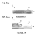
- the composite material plate 10 is formed by laminating and uniting composite member forming materials 10a in the form of sheets containing a fiber and a resin.
- a composite material plate 10' having an increased thickness is formed, as illustrated in close-up in Fig. 7(b) , it is necessary to prepare, in addition to the composite member forming materials 10a, composite member forming materials 10a' having a length different from the composite member forming materials 10a, and to laminate and unite them in a tapered shape. That is, such production of the composite material plate 10' is complex and costs much.
- Patent Document 1 discloses a fastener joint structure for a composite material article where a boss obtained by forming a composite material in a spiral form is provided at a joint portion of the composite material article, and a fastener member such as a bolt is inserted into a joint hole through the boss.
- a fastener member such as a bolt
- the present invention has been made in view of the above problems of prior art and is to provide a joint structure for a composite member which has a structure being lightweight and obtainable at a low cost, which is easy to manufacture, and which is resistible against a large shear load.
- the present invention has been made to solve the above problems and provides a joint structure for a composite member made from a composite material, comprising:
- the above joint structure for a composite member of the present invention comprises a plate for increasing thickness adhered to at least one side of the composite member.
- the bearing area is increased by the thickness of the plate for increasing thickness, whereby the bearing contact pressure may be suppressed.
- the plate for increasing thickness may be adhered only to a portion where the thickness is required to be increased, whereby an additional material may not be necessary, and a light-weight and low-cost structure may be obtained.
- adhesion means to adhere a plate for increasing thickness to a composite member.
- Specific examples of adhesion method include a method of adhering the plate for increasing thickness to the composite member with an adhesive, a method of stacking the composite member and the plate for increasing thickness via an adhesive and mechanically bonding them by pressure, and a method of heating the composite member and the plate for increasing thickness in a state where they are stacked to unifying them in the case where the composite member or the plate for increasing thickness contains a thermosetting resin.
- the plate for increasing thickness may be made from the same composite material as the composite member.
- the plate for increasing thickness is made from the same composite material as the composite member, there is no difference in thermal expansion between the plate for increasing thickness and the composite member, whereby the adhesion property may be stable with no influence by thermal stress or thermal deformation associated with a change in temperature.
- the plate for increasing thickness may be made from a metal material.
- the plate for increasing thickness is made from a metal material
- a joint structure for a composite member taking advantage of the properties of the metal material may be obtained. That is, for example, by making the plate for increasing thickness from a metal material having a high ductility and providing a through-hole formed through the composite member having a diameter larger than the through-hole formed through the plate for increasing thickness, the bearing contact pressure may be homogenized among a plurality of fastener members, as will be described later.
- the plate for increasing thickness may be made from a resin-based material having a ductility higher than the composite member.
- the bearing contact pressure may be homogenized among a plurality of fastener members, as will be described later.
- the plate for increasing thickness is adhered to each of both sides of the composite member.
- the stress distribution of the composite member may be uniform as compared with the case where the plate for increasing thickness is adhered only to one side of the composite member. Further, the adhesion area between the plate for increasing thickness and the composite material is twice, whereby the shear force acting on the adhesion surface may be reduced by 1/2.
- the bearing area may be increased by adhering a plate for increasing thickness to a composite member to prevent an excessive bearing contact pressure from acting.
- Fig. 1 is a diagram illustrating an embodiment of the joint structure for a composite member according to the present invention, and Fig. 1(a) is a plan view, and Fig. 1(b) is a cross-sectional view along line a-a.
- the joint structure for a composite member 1 is a joint structure for a composite material plate 10 (a composite member) in the shape of a flat plate made from a composite material, wherein a counterpart member 20 is joined to the composite material plate 10 with a plurality (2 x 4) of bolts 30 and nuts 32 (fastener members).
- a composite material means a fiber-reinforced composite material having a fiber as a reinforcing material and a resin as a matrix material.
- CFRP carbon fiber reinforced plastic
- GFRP glass fiber reinforced plastic
- BFRP boron fiber reinforced plastic
- AFRP aramid fiber reinforced plastic
- the counterpart member 20 to be joined to the composite material plate 10 is not particularly limited and may be a member made from the same composite material as the composite material plate 10 or a member made from another material.
- a large horizontal force H acts on the counterpart member 20, whereby a shear force acts on the joint surface between the composite material plate 10 and the counterpart material 20.
- a bearing contact pressure acts at the contact portion (portion a in Fig. 1(b) ) between the bolt 30 and the composite material plate 10.
- adhesion means to adhere a plate for increasing thickness to a composite member.
- adhesion method include, in addition to the above method of adhesion, a method of stacking the composite member and the plate for increasing thickness via an adhesive and mechanically bonding them by pressure, and a method of heating the composite member and the plate for increasing thickness in a state where they are stacked to unifying them in the case where the composite member or the plate for increasing thickness contains a thermosetting resin.
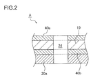
- the composite material plate 10 and the counterpart member 20 are fastened together by inserting the bolt 30 into a through-hole 24 formed through the composite material plate 10, the plates for increasing thickness 40a and 40b, and a flange 20a of the counterpart member 20, and fixing it by tightening the nut 32.
- the plates for increasing thickness 40a and 40b are adhered to the composite material plate 10 as above, it is possible to increase the bearing area by the thickness of the plates for increasing thickness 40a and 40b, thereby to suppress the bearing contact pressure.
- the plates for increasing thickness 40a and 40b may be made from the same composite material as the composite material plate 10, or may be made from a material different from the composite material plate 10.
- a proper material may be employed in accordance with e.g. the use of the composite material plate 10.
- the plates for increasing thickness 40a and 40b are made from a material different from the composite material plate 10, they are preferably made from a material having a ductility higher than the composite material plate 10 e.g. a metal material or a resin-based material having a ductility higher than the composite material plate 10, for the reason described later.
- An advantageous point in the case where the plates for increasing thickness 40a and 40b are made from the same composite material as the composite material plate 10, may, for example, be that there is no difference in thermal expansion between the composite material plate 10, and the plates for increasing thickness 40a and 40b, whereby the adhesion property may be stable with no influence by thermal stress or thermal deformation associated with a change in temperature.
- an advantageous point in the case where the plates for increasing thickness 40a and 40b are made from a metal material may, for example, be that a joint structure for a composite material plate 10 taking advantage of the properties of the metal material may be obtained.
- the bearing contact pressure may be homogenized among the bolts 30a to 30d.
- an advantageous point in the case where the plates for increasing thickness 40a and 40b are made from a resin-based material having a ductility higher than the composite material plate 10, may be the same, and by providing a through-hole formed through the composite material plate 10 having a diameter larger than the through-hole formed through the plates for increasing thickness 40a and 40b, the bearing contact pressure may be homogenized among the bolts 30a to 30d. This will be described with reference to Fig. 3 and Fig. 4 .
- Fig. 3 is a diagram illustrating another embodiment of the joint structure for a composite member according to the present invention, and Fig. 3(a) is a cross-sectional view, and Fig. 3(b) is an enlarged view of portion B.
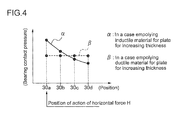
- Fig. 4 is a chart showing a relationship between a position of a bolt and a bearing contact pressure, and in Fig. 4 , ⁇ is a graph in a case where an inductile material is employed for the plates for increasing thickness 40a and 40b, and ⁇ is a graph in a case where a material having a high ductility (e.g. a metal material) is employed for the plates for increasing thickness 40a and 40b.
- a material having a high ductility e.g. a metal material
- a through-hole 26a of the composite material plate has a diameter larger than a diameter of a through-hole 26b of the plates for increasing thickness 40a and 40b, which is different from the above-described embodiment.
- the bearing contact pressure is largest at the bolt 30a which is in the vicinity of the position of action of the horizontal force H, and it becomes smaller as the distance from the position of action of the horizontal force H becomes larger; however, in the case of forming the through-hole 26 as described above and employing a metal material or a resin-based material having a ductility higher than the composite material plate 10 for the plates for increasing thickness 40a and 40b, in the through-hole 26 into which the bolt 30 is inserted, the bolt 30a and the through-hole 26b formed through the plates for increasing thickness 40a and 40b come into contact with each other, and the plates for increasing thickness 40a and 40b become plastically deformed, whereby the diameter of the through-hole 26b is expanded.
- This amount of expansion is largest at the through-hole 26 into which the bolt 30a at which the bearing contact pressure is large, is inserted, and the amount of expansion is smallest at the through-hole 26 into which the bolt 30d at which the bearing contact pressure is small, is inserted.
- the contact between the bolts 30a to 30d and the plates for increasing thickness 40a and 40b may thereby be homogenized, and the bearing contact pressure may be homogenized among the bolts 30a to 30d, as shown by ⁇ in Fig. 4 .
- a metal material which has a high ductility, a high strength and a light weight is preferred, and for example, a titanium alloy, a high-nickel alloy or a cobalt alloy such as MP-35N (AMS5758) or Inco600 (AMS5687), or a corrosion-resistant steel such as A286 (AMS5731, AMS5737), may be particularly preferably used.
- the resin-based material used for the plates for increasing thickness 40a and 40b in the case of employing CFRP for the composite material plate 10, may, for example, be a composite material having a ductility higher than CFRP, such as GFRP or AFRP.
- CFRP CFRP
- a resin material which is not fiber-reinforced may also be employed, and a resin material having a strength equal or more than an epoxy resin and having a ductility higher than the composite material plate 10, e.g. polycarbonate, may be mentioned.
- the joint structure for a composite member comprises the plates for increasing thickness 40a and 40b are adhered to the both sides of the composite material plate 10, and the bearing area may be increased by the thickness of the plates for increasing thickness 40a and 40b, whereby the bearing contact pressure may be suppressed.
- adhering of the plates for increasing thickness 40a and 40b to the composite material plate 10 there is less restriction than in increasing the thickness of the composite member itself as in conventional art, and such a joint structure is easy to manufacture.
- the plates for increasing thickness 40a and 40b may be adhered only to a portion where the thickness is required to be increased, whereby an additional material may not be necessary, and a light-weight and low-cost structure may be obtained.
- the plates for increasing thickness 40a and 40b are adhered to the both sides of the composite material plate 10. It is preferred that the plates for increasing thickness 40a and 40b are adhered to each of both sides of the composite material plate 10 as above because the stress distribution of the composite material plate 10 may thereby be uniform as compared with the case where the plate for increasing thickness 40 is adhered only to one side of the composite material plate 10. Further, the adhesion area between the plate for increasing thickness 40 and the composite material plate 10 becomes twice, whereby the shear force acting on one adhesion surface may be reduced by 1/2.
- the joint structure 1 for a composite member of the present invention is not limited thereto, and it may be such that the plate for increasing thickness is adhered to at least one side of the composite member.
- an example of the joint structure 1 for the composite material plate 10 in the shape of a flat plate is not limited to a composite member in the shape of a flat plate, and it may, for example, be a composite member in the form of a tube.
- the present invention may be applicable in various industrial fields including aircrafts, ships and automobiles, as a joint structure for a composite member made from a composite material.
Landscapes
- Engineering & Computer Science (AREA)
- Mechanical Engineering (AREA)
- General Engineering & Computer Science (AREA)
- Connection Of Plates (AREA)
Abstract
Description
- The present invention relates to a joint structure for a composite member made from a composite material.
- Fiber-reinforced composite materials (hereinafter referred to as "composite material(s)") having a fiber as a reinforcing material and a resin as a matrix material, including CFRP (carbon fiber reinforced plastic), GFRP (glass fiber reinforced plastic), BFRP (boron fiber reinforced plastic) and AFRP (aramid fiber reinforced plastic), are used as materials having light weight and high strength in various fields. For example, CFRP employing a carbon fiber reinforced plastic has both extremely high strength and light weight, and it is widely used in various industrial fields including aircrafts, ships and automobiles.
- When a composite member made from such a composite material is joined to a counterpart member as a target of joint, a joint structure 1' where a fastener member such as a bolt 30 is inserted into a through-
hole 24 formed through a composite material plate 10 (a composite member) and aflange 20a of acounterpart member 20, and a nut 32 is tightened to fix the bolt 30, to fasten thecomposite material plate 10 and thecounterpart member 20 together, as shown inFig. 5 , is usually employed. - In the joint structure 1' of such a type, in a case where a horizontal force H' acts on the
counterpart member 20 and a shear load acts in a direction in which thecomposite material plate 10 and thecounterpart member 20 may be misaligned, the nut 32 is strongly tightened to strongly fasten thecomposite material plate 10 and thecounterpart member 20 together by a bolt axial force, and the joint structure 1' resists to the shear load by a frictional force on a joint surface between thecomposite material plate 10 and thecounterpart member 20. However, in a case where thecomposite material plate 10 is used as a skin for a main wing of an airplane, for example, in order to obtain a secure design, the joint structure 1' is designed so as to be capable of resisting the shear load by a contact pressure (bearing contact pressure) at a contact portion (a' inFig. 5 ) between the bolt 30 and thecomposite material plate 10 even when the nut is loosened. - In a case where the acting horizontal force H is large, an increased number of bolts 30 are used, and bolts 30 having a larger size are used. However, if such countermeasures are insufficient, the joint structure 1' is designed so that the thickness of the composite material plate 10' is increased to increase the area of contact portion a' (bearing area) between the bolt 30 and the composite material plate 10', whereby the bearing contact pressure is suppressed under an acceptable value.
- [PTL1]
JP Sho58-71151A - However, in increasing the thickness of the above composite material plate 10', there are problems in production of the composite member, as described below.
- That is, as schematically illustrated in
Fig. 7(a) , thecomposite material plate 10 is formed by laminating and uniting compositemember forming materials 10a in the form of sheets containing a fiber and a resin. Thus, when a composite material plate 10' having an increased thickness is formed, as illustrated in close-up inFig. 7(b) , it is necessary to prepare, in addition to the compositemember forming materials 10a, compositemember forming materials 10a' having a length different from the compositemember forming materials 10a, and to laminate and unite them in a tapered shape. That is, such production of the composite material plate 10' is complex and costs much. - Further, there is restriction in the rate of change of the thickness (angle of gradient of the taper) of the composite material plate 10', and it is not possible to change the thickness of the plate very drastically. Thus, there is a problem such that a thickness of a part other than the part of which thickness needs to be increased, is necessarily increased, whereby additional materials are required, and the weight of the composite material plate 10' is necessarily increased.
- Further,
Patent Document 1 discloses a fastener joint structure for a composite material article where a boss obtained by forming a composite material in a spiral form is provided at a joint portion of the composite material article, and a fastener member such as a bolt is inserted into a joint hole through the boss. However, in the joint structure of thePatent Document 1, there is a problem such that it is difficult to provide the boss of a spiral form at the joint portion of the composite material article. - The present invention has been made in view of the above problems of prior art and is to provide a joint structure for a composite member which has a structure being lightweight and obtainable at a low cost, which is easy to manufacture, and which is resistible against a large shear load.
- The present invention has been made to solve the above problems and provides a joint structure for a composite member made from a composite material, comprising:
- a plate for increasing thickness adhered to at least one side of the composite member;
- wherein the composite member and a counterpart member are fastened together by inserting and fixing a fastener member into a through-hole formed through the composite member, the plate for increasing thickness, and the counterpart member to be joined to the composite member.
- The above joint structure for a composite member of the present invention comprises a plate for increasing thickness adhered to at least one side of the composite member. Thus, the bearing area is increased by the thickness of the plate for increasing thickness, whereby the bearing contact pressure may be suppressed. In adhering of such a plate for increasing thickness, there is less restriction than in increasing the thickness of the composite member itself, and such a joint structure is easy to manufacture. Further, the plate for increasing thickness may be adhered only to a portion where the thickness is required to be increased, whereby an additional material may not be necessary, and a light-weight and low-cost structure may be obtained.
- In the present description, "adhere" means to adhere a plate for increasing thickness to a composite member. Specific examples of adhesion method include a method of adhering the plate for increasing thickness to the composite member with an adhesive, a method of stacking the composite member and the plate for increasing thickness via an adhesive and mechanically bonding them by pressure, and a method of heating the composite member and the plate for increasing thickness in a state where they are stacked to unifying them in the case where the composite member or the plate for increasing thickness contains a thermosetting resin.
- In the above invention, the plate for increasing thickness may be made from the same composite material as the composite member.
- When the plate for increasing thickness is made from the same composite material as the composite member, there is no difference in thermal expansion between the plate for increasing thickness and the composite member, whereby the adhesion property may be stable with no influence by thermal stress or thermal deformation associated with a change in temperature.
- In the above invention, the plate for increasing thickness may be made from a metal material.
- When the plate for increasing thickness is made from a metal material, a joint structure for a composite member taking advantage of the properties of the metal material may be obtained. That is, for example, by making the plate for increasing thickness from a metal material having a high ductility and providing a through-hole formed through the composite member having a diameter larger than the through-hole formed through the plate for increasing thickness, the bearing contact pressure may be homogenized among a plurality of fastener members, as will be described later.
- In the above invention, the plate for increasing thickness may be made from a resin-based material having a ductility higher than the composite member.
- By making the plate for increasing thickness from a resin-based material having a ductility higher than the composite member and providing a through-hole formed through the composite member having a diameter larger than the through-hole formed through the plate for increasing thickness, the bearing contact pressure may be homogenized among a plurality of fastener members, as will be described later.
- Further, for example, by employing a metal material having a high strength and providing a through-hole formed through the composite member having a diameter larger than the through-hole formed through the plate for increasing thickness, it is possible to obtain a structure resistible against a shear load only by the plate for increasing thickness without bringing the composite member into contact with the fastener member.
- In the above invention, it is preferred that the plate for increasing thickness is adhered to each of both sides of the composite member.
- When the plate for increasing thickness is adhered to each of both sides of the composite member, the stress distribution of the composite member may be uniform as compared with the case where the plate for increasing thickness is adhered only to one side of the composite member. Further, the adhesion area between the plate for increasing thickness and the composite material is twice, whereby the shear force acting on the adhesion surface may be reduced by 1/2.
- According to the present invention, the bearing area may be increased by adhering a plate for increasing thickness to a composite member to prevent an excessive bearing contact pressure from acting. Thus, it is possible to provide a joint structure for a composite member which has a structure being lightweight and obtainable at a low cost, which is easy to manufacture, and which is resistible against a large shear load, as compared with a conventional joint structure for a composite member where the thickness of the composite member itself is increased.
-
- [
FIG. 1(a)] Fig. 1(a) is a diagram illustrating an embodiment of the joint structure for a composite member according to the present invention. - [
FIG. 1(b)] Fig. 1(b) is a diagram illustrating an embodiment of the joint structure for a composite member according to the present invention. - [
FIG. 2] Fig. 2 is an enlarged cross-sectional view illustrating portion A inFig. 1(a) . - [
FIG. 3(a)] Fig. 3(a) is a diagram illustrating another embodiment of the joint structure for a composite member according to the present invention. - [
FIG. 3(b)] Fig. 3(b) is a diagram illustrating another embodiment of the joint structure for a composite member according to the present invention. - [
FIG. 4] Fig. 4 is a chart showing a relationship between a position of a bolt and a bearing contact pressure. - [
FIG.5] Fig. 5 is a cross-sectional view illustrating a conventional joint structure for a composite member. - [
FIG. 6] Fig. 6 is a cross-sectional view illustrating a conventional joint structure for a composite member. - [
FIG.7(a)] Fig. 7(a) is a schematic cross-sectional view schematically illustrating portion A' and portion B' inFig. 6 . - [
FIG.7(b)] Fig. 7(b) is a schematic cross-sectional view schematically illustrating portion A' and portion B' inFig. 6 . - Embodiments of the present invention will now be described in detail with reference to the accompanying drawings.
- It is intended, however, that unless particularly specified, dimensions, materials, shapes, relative positions and the like of components described in the embodiments shall be interpreted as illustrative only and not limitative of the scope of the present invention.
-
Fig. 1 is a diagram illustrating an embodiment of the joint structure for a composite member according to the present invention, andFig. 1(a) is a plan view, andFig. 1(b) is a cross-sectional view along line a-a. - As illustrated in
Fig. 1 , the joint structure for acomposite member 1 according to an embodiment of the present invention is a joint structure for a composite material plate 10 (a composite member) in the shape of a flat plate made from a composite material, wherein acounterpart member 20 is joined to thecomposite material plate 10 with a plurality (2 x 4) of bolts 30 and nuts 32 (fastener members). - In the present description, "a composite material" means a fiber-reinforced composite material having a fiber as a reinforcing material and a resin as a matrix material. Specific examples thereof include CFRP (carbon fiber reinforced plastic), GFRP (glass fiber reinforced plastic), BFRP (boron fiber reinforced plastic) and AFRP (aramid fiber reinforced plastic).
- The
counterpart member 20 to be joined to thecomposite material plate 10 is not particularly limited and may be a member made from the same composite material as thecomposite material plate 10 or a member made from another material. In this embodiment, a large horizontal force H acts on thecounterpart member 20, whereby a shear force acts on the joint surface between thecomposite material plate 10 and thecounterpart material 20. Further, as a reaction force to the shear force acting on the composite material, a bearing contact pressure acts at the contact portion (portion a inFig. 1(b) ) between the bolt 30 and thecomposite material plate 10. - Further, as illustrated in
Fig. 1 , on the both sides of thecomposite material plate 10, plates for increasingthickness thickness - Then, as illustrated in
Fig. 2 , thecomposite material plate 10 and thecounterpart member 20 are fastened together by inserting the bolt 30 into a through-hole 24 formed through thecomposite material plate 10, the plates for increasingthickness flange 20a of thecounterpart member 20, and fixing it by tightening the nut 32. When the plates for increasingthickness composite material plate 10 as above, it is possible to increase the bearing area by the thickness of the plates for increasingthickness - The plates for increasing
thickness composite material plate 10, or may be made from a material different from thecomposite material plate 10. A proper material may be employed in accordance with e.g. the use of thecomposite material plate 10. In a case where the plates for increasingthickness composite material plate 10, they are preferably made from a material having a ductility higher than thecomposite material plate 10 e.g. a metal material or a resin-based material having a ductility higher than thecomposite material plate 10, for the reason described later. - An advantageous point in the case where the plates for increasing
thickness composite material plate 10, may, for example, be that there is no difference in thermal expansion between thecomposite material plate 10, and the plates for increasingthickness - Further, an advantageous point in the case where the plates for increasing
thickness composite material plate 10 taking advantage of the properties of the metal material may be obtained. Specifically, for example, by making the plates for increasingthickness composite material plate 10 having a diameter larger than the through-hole formed through the plates for increasingthickness bolts 30a to 30d. Further, an advantageous point in the case where the plates for increasingthickness composite material plate 10, may be the same, and by providing a through-hole formed through thecomposite material plate 10 having a diameter larger than the through-hole formed through the plates for increasingthickness bolts 30a to 30d. This will be described with reference toFig. 3 andFig. 4 . -
Fig. 3 is a diagram illustrating another embodiment of the joint structure for a composite member according to the present invention, andFig. 3(a) is a cross-sectional view, andFig. 3(b) is an enlarged view of portion B.Fig. 4 is a chart showing a relationship between a position of a bolt and a bearing contact pressure, and inFig. 4 , α is a graph in a case where an inductile material is employed for the plates for increasingthickness thickness - In the joint structure for a composite member as illustrated in
Fig. 3 , in the through-hole 26 formed through thecomposite material plates 10, the plates for increasingthickness flange 20a of thecounterpart member 20, a through-hole 26a of the composite material plate has a diameter larger than a diameter of a through-hole 26b of the plates for increasingthickness - As shown by α in
Fig. 4 , the bearing contact pressure is largest at thebolt 30a which is in the vicinity of the position of action of the horizontal force H, and it becomes smaller as the distance from the position of action of the horizontal force H becomes larger; however, in the case of forming the through-hole 26 as described above and employing a metal material or a resin-based material having a ductility higher than thecomposite material plate 10 for the plates for increasingthickness hole 26 into which the bolt 30 is inserted, thebolt 30a and the through-hole 26b formed through the plates for increasingthickness thickness hole 26b is expanded. This amount of expansion is largest at the through-hole 26 into which thebolt 30a at which the bearing contact pressure is large, is inserted, and the amount of expansion is smallest at the through-hole 26 into which thebolt 30d at which the bearing contact pressure is small, is inserted. The contact between thebolts 30a to 30d and the plates for increasingthickness bolts 30a to 30d, as shown by β inFig. 4 . Thus, it is possible to prevent a concentration of the bearing contact pressure to one of the bolts 30, thereby to reduce a breakage risk of a bolt 30. - Further, in this embodiment, for example, by employing a metal material having a high strength for the plates for increasing
thickness thickness composite material plate 10 into contact with the bolt 30. - In the present invention, as the metal material used for the plates for increasing
thickness - Further, in the present invention, as the resin-based material used for the plates for increasing
thickness composite material plate 10, may, for example, be a composite material having a ductility higher than CFRP, such as GFRP or AFRP. Further, as the resin-based material according to the present invention, a resin material which is not fiber-reinforced may also be employed, and a resin material having a strength equal or more than an epoxy resin and having a ductility higher than thecomposite material plate 10, e.g. polycarbonate, may be mentioned. - As described above, the joint structure for a composite member according to the present invention comprises the plates for increasing
thickness composite material plate 10, and the bearing area may be increased by the thickness of the plates for increasingthickness thickness composite material plate 10, there is less restriction than in increasing the thickness of the composite member itself as in conventional art, and such a joint structure is easy to manufacture. Further, according to the present invention, the plates for increasingthickness - In the above embodiment, the plates for increasing
thickness composite material plate 10. It is preferred that the plates for increasingthickness composite material plate 10 as above because the stress distribution of thecomposite material plate 10 may thereby be uniform as compared with the case where the plate for increasing thickness 40 is adhered only to one side of thecomposite material plate 10. Further, the adhesion area between the plate for increasing thickness 40 and thecomposite material plate 10 becomes twice, whereby the shear force acting on one adhesion surface may be reduced by 1/2. - However, the
joint structure 1 for a composite member of the present invention is not limited thereto, and it may be such that the plate for increasing thickness is adhered to at least one side of the composite member. - Further, in the above embodiment, an example of the
joint structure 1 for thecomposite material plate 10 in the shape of a flat plate; however, the composite member according to the present invention is not limited to a composite member in the shape of a flat plate, and it may, for example, be a composite member in the form of a tube. - Some preferred embodiments of the present invention are described above; however, the present invention is by no means limited thereto and further modifications and variations may be made without departing from the scope of the invention.
- The present invention may be applicable in various industrial fields including aircrafts, ships and automobiles, as a joint structure for a composite member made from a composite material.
Claims (6)
- A joint structure for a composite member made from a composite material, comprising:a plate for increasing thickness adhered to at least one side of the composite member;wherein the composite member and a counterpart member are fastened together by inserting and fixing a fastener member into a through-hole formed through the composite member, the plate for increasing thickness, and the counterpart member to be joined to the composite member.
- The joint structure for a composite member according to claim 1, wherein the plate for increasing thickness is made from the same composite material as the composite member.
- The joint structure for a composite member according to claim 1, wherein the plate for increasing thickness is made from a metal material.
- The joint structure for a composite member according to claim 1, wherein the plate for increasing thickness is made from a resin-based material having a ductility higher than the composite member.
- The joint structure for a composite member according to claim 3 or 4, wherein the through-hole formed through the composite member has a diameter larger than a diameter of the through-hole formed through the plate for increasing thickness.
- The joint structure for a composite member according to any one of claims 1 to 5, wherein the plate for increasing thickness is adhered to each of both sides of the composite member.
Applications Claiming Priority (2)
| Application Number | Priority Date | Filing Date | Title |
|---|---|---|---|
| JP2011288838A JP5924934B2 (en) | 2011-12-28 | 2011-12-28 | Composite joint structure |
| PCT/JP2012/082644 WO2013099673A1 (en) | 2011-12-28 | 2012-12-17 | Joint structure for composite |
Publications (3)
| Publication Number | Publication Date |
|---|---|
| EP2799728A1 true EP2799728A1 (en) | 2014-11-05 |
| EP2799728A4 EP2799728A4 (en) | 2015-12-23 |
| EP2799728B1 EP2799728B1 (en) | 2020-02-05 |
Family
ID=48697165
Family Applications (1)
| Application Number | Title | Priority Date | Filing Date |
|---|---|---|---|
| EP12861083.9A Active EP2799728B1 (en) | 2011-12-28 | 2012-12-17 | Joint structure for composite |
Country Status (5)
| Country | Link |
|---|---|
| US (1) | US10094405B2 (en) |
| EP (1) | EP2799728B1 (en) |
| JP (1) | JP5924934B2 (en) |
| CN (1) | CN104024661A (en) |
| WO (1) | WO2013099673A1 (en) |
Families Citing this family (10)
| Publication number | Priority date | Publication date | Assignee | Title |
|---|---|---|---|---|
| GB0901640D0 (en) * | 2009-02-03 | 2009-03-11 | Airbus Uk Ltd | Joint |
| JP5907422B2 (en) * | 2012-03-30 | 2016-04-26 | 広島県 | Fastening structure of fiber reinforced resin material |
| DE102015202036A1 (en) * | 2015-02-05 | 2016-08-11 | Bayerische Motoren Werke Aktiengesellschaft | Arrangement of a first and a second component |
| DE102015202037A1 (en) * | 2015-02-05 | 2016-08-11 | Bayerische Motoren Werke Aktiengesellschaft | component arrangement |
| US10727549B2 (en) * | 2015-04-28 | 2020-07-28 | Sanyo Electric Co., Ltd. | Power supply device and vehicle provided therewith |
| JP6354662B2 (en) * | 2015-05-27 | 2018-07-11 | トヨタ自動車株式会社 | Vehicle member joining structure and vehicle member joining method |
| US20190003514A1 (en) * | 2017-06-30 | 2019-01-03 | Spartan Motors, Inc. | Dual laminate galvanic isolation |
| JP7178549B2 (en) * | 2018-08-20 | 2022-11-28 | トーヨーカネツ株式会社 | Anchor strap structure |
| US11116505B2 (en) * | 2018-12-28 | 2021-09-14 | Cilag Gmbh International | Applicator for surgical stapler buttress |
| CN110410388B (en) * | 2019-07-12 | 2024-03-08 | 中国船舶重工集团公司第七二五研究所 | A matching connection structure of reinforced composite materials and metal materials |
Family Cites Families (28)
| Publication number | Priority date | Publication date | Assignee | Title |
|---|---|---|---|---|
| US3828515A (en) * | 1969-12-16 | 1974-08-13 | G Galgoczy | Non-slip, high strength bolted joints |
| US3879916A (en) * | 1974-07-22 | 1975-04-29 | Us Air Force | Fatigue resistant spanwise splice |
| JPS5871151A (en) | 1981-10-23 | 1983-04-27 | 川崎重工業株式会社 | Fastener joint structure of composite material product |
| JPS59174217A (en) | 1983-03-24 | 1984-10-02 | Mitsubishi Electric Corp | Rolling equipment |
| JPS59174217U (en) * | 1983-05-06 | 1984-11-21 | 三井造船株式会社 | Reinforced plastic joint structure |
| US4579475A (en) * | 1984-01-23 | 1986-04-01 | The United States Of America As Represented By The Administrator Of The National Aeronautics And Space Administration | Optimized bolted joint |
| GB2212237B (en) * | 1987-11-11 | 1991-08-21 | Avdel Ltd | Bush |
| US5222827A (en) * | 1992-03-04 | 1993-06-29 | Northrop Corporation | Fastener installation and method for composite members |
| JP2892637B2 (en) * | 1997-07-08 | 1999-05-17 | 川崎重工業株式会社 | The method of joining the central part of the composite structure of the leading vehicle of the Shinkansen |
| GB9807198D0 (en) * | 1998-04-04 | 1998-06-03 | British Aerospace | Adhesively bonded joints in carbon fibre composite structures |
| DE19816099A1 (en) | 1998-04-10 | 1999-10-21 | Goetz Metall Anlagen | Connection assembly for use in steel constructions esp. in building construction |
| KR20000048303A (en) * | 1998-12-26 | 2000-07-25 | 정훈광 | apparatus and method for jointing a plurality of steel members using shear rings |
| DE19925953C1 (en) * | 1999-06-08 | 2000-09-07 | Deutsch Zentr Luft & Raumfahrt | Bolted connection transmitting transverse forces in laminated fibrous composite structures, includes resilient filler in bolt holes elongated as a function of their distance from center and further reinforced by local layers of metal sheet |
| FR2817926B1 (en) * | 2000-12-08 | 2003-02-28 | Eads Airbus Sa | OPTIMIZED ASSEMBLY METHOD OF TWO SUBSTANTIALLY PLANAR PARTS |
| US6648273B2 (en) * | 2001-10-30 | 2003-11-18 | The Boeing Company | Light weight and high strength fuselage |
| DE102004045845B3 (en) * | 2004-09-20 | 2005-12-15 | Deutsches Zentrum für Luft- und Raumfahrt e.V. | Compound fiber component, of overlaid plates, has openings along the load-bearing direction to take bolts with prefabricated softening bolt linings at the outermost openings |
| US7325771B2 (en) * | 2004-09-23 | 2008-02-05 | The Boeing Company | Splice joints for composite aircraft fuselages and other structures |
| US7721495B2 (en) * | 2005-03-31 | 2010-05-25 | The Boeing Company | Composite structural members and methods for forming the same |
| US9302427B2 (en) * | 2005-03-31 | 2016-04-05 | The Boeing Company | Aeropspace structure including composite beam chord clamped between reinforcement plates |
| EP1801427A1 (en) * | 2005-12-21 | 2007-06-27 | Airbus Espana, S.L. | Metallic local reinforcement for heavy loaded joints of composite components |
| JP5008040B2 (en) * | 2007-04-13 | 2012-08-22 | 大成プラス株式会社 | Titanium alloy composite and its joining method |
| JP5094849B2 (en) * | 2007-04-24 | 2012-12-12 | 大成プラス株式会社 | Stainless steel composite |
| FR2915458B1 (en) * | 2007-04-25 | 2010-01-01 | Airbus France | ASSEMBLY OF FUSELAGE PANELS OF AN AIRCRAFT |
| US8398027B2 (en) * | 2007-09-17 | 2013-03-19 | The Boeing Company | Method and apparatus for reinforcing composite structures |
| JP2011042030A (en) * | 2007-12-18 | 2011-03-03 | Taisei Plas Co Ltd | Bonded structure of metal and adherend and process for producing the same |
| JP2010240930A (en) | 2009-04-03 | 2010-10-28 | Toyota Industries Corp | Fitting structure of fiber-reinforced composite material |
| GB0906953D0 (en) | 2009-04-23 | 2009-06-03 | Airbus Uk Ltd | Composite structure |
| JP5172983B2 (en) | 2011-02-25 | 2013-03-27 | 富士重工業株式会社 | Bonding structure between fiber reinforced resin and metal, and bonding method between fiber reinforced resin and metal |
-
2011
- 2011-12-28 JP JP2011288838A patent/JP5924934B2/en active Active
-
2012
- 2012-12-17 US US14/360,754 patent/US10094405B2/en active Active
- 2012-12-17 CN CN201280061547.1A patent/CN104024661A/en active Pending
- 2012-12-17 EP EP12861083.9A patent/EP2799728B1/en active Active
- 2012-12-17 WO PCT/JP2012/082644 patent/WO2013099673A1/en not_active Ceased
Also Published As
| Publication number | Publication date |
|---|---|
| EP2799728A4 (en) | 2015-12-23 |
| US10094405B2 (en) | 2018-10-09 |
| CN104024661A (en) | 2014-09-03 |
| JP2013137075A (en) | 2013-07-11 |
| WO2013099673A1 (en) | 2013-07-04 |
| JP5924934B2 (en) | 2016-05-25 |
| EP2799728B1 (en) | 2020-02-05 |
| US20150093185A1 (en) | 2015-04-02 |
Similar Documents
| Publication | Publication Date | Title |
|---|---|---|
| EP2799728B1 (en) | Joint structure for composite | |
| JP5287279B2 (en) | Part fastening structure | |
| JP5818715B2 (en) | Composite structure | |
| EP2137063B1 (en) | Attachment arrangement for attaching a component to the fuselage of an aircraft, aircraft and method for constructing an attachment arrangement | |
| EP2487106B1 (en) | Composite material structure, as well as aircraft wing and fuselage provided therewith | |
| EP2492083B1 (en) | Joint structure for fiber reinforced resin and metal, and joining method for fiber reinforced resin and metal | |
| US20100233424A1 (en) | Composite structures employing quasi-isotropic laminates | |
| JP5808112B2 (en) | Composite structure and aircraft main wing provided with the same | |
| US20110290941A1 (en) | Attachment system of aircraft components | |
| JP2012162147A (en) | Composite material structure, and aircraft main wing and fuselage provided therewith | |
| US20140377500A1 (en) | Composite structure, aircraft wing and aircraft fuselage including composite structure, and method of manufacturing composite structure | |
| EP1151917B1 (en) | Skin/bulkhead structure | |
| CN102317057B (en) | Method for producing a shell body and corresponding body | |
| EP2532581A1 (en) | T-profile junction of composite materials | |
| US20170066216A1 (en) | Composite material structure and method of manufacturing composite material structure | |
| EP1801428B1 (en) | Metallic local reinforcement for heavy loaded joints of composite components | |
| US6514593B1 (en) | Mechanically locking Z-pins | |
| EP1533433A1 (en) | Sandwich panel and a method of producing a sandwich panel | |
| US9682519B2 (en) | Integral composite bushing system and method | |
| EP3095960B1 (en) | Vane connection part structure and jet engine utilizing same | |
| EP2922696B1 (en) | Multi-axial fabrics, polymer-fiber laminates, and bodies incorporating same for connecting applications | |
| US8291671B2 (en) | Joint arrangement for composite-material structural members | |
| JP6558185B2 (en) | Girder structure | |
| EP2453141B1 (en) | Adhesively-bonded structural composite joint utilizing shoulder-centered sleeves | |
| JP2023145292A (en) | Molded object reinforcing member, molded object and connection structure using the same |
Legal Events
| Date | Code | Title | Description |
|---|---|---|---|
| PUAI | Public reference made under article 153(3) epc to a published international application that has entered the european phase |
Free format text: ORIGINAL CODE: 0009012 |
|
| 17P | Request for examination filed |
Effective date: 20140528 |
|
| AK | Designated contracting states |
Kind code of ref document: A1 Designated state(s): AL AT BE BG CH CY CZ DE DK EE ES FI FR GB GR HR HU IE IS IT LI LT LU LV MC MK MT NL NO PL PT RO RS SE SI SK SM TR |
|
| DAX | Request for extension of the european patent (deleted) | ||
| RA4 | Supplementary search report drawn up and despatched (corrected) |
Effective date: 20151124 |
|
| RIC1 | Information provided on ipc code assigned before grant |
Ipc: B29C 65/64 20060101ALI20151118BHEP Ipc: F16B 5/02 20060101AFI20151118BHEP Ipc: B29C 65/56 20060101ALI20151118BHEP |
|
| STAA | Information on the status of an ep patent application or granted ep patent |
Free format text: STATUS: EXAMINATION IS IN PROGRESS |
|
| 17Q | First examination report despatched |
Effective date: 20171020 |
|
| GRAP | Despatch of communication of intention to grant a patent |
Free format text: ORIGINAL CODE: EPIDOSNIGR1 |
|
| STAA | Information on the status of an ep patent application or granted ep patent |
Free format text: STATUS: GRANT OF PATENT IS INTENDED |
|
| INTG | Intention to grant announced |
Effective date: 20190920 |
|
| GRAS | Grant fee paid |
Free format text: ORIGINAL CODE: EPIDOSNIGR3 |
|
| GRAA | (expected) grant |
Free format text: ORIGINAL CODE: 0009210 |
|
| STAA | Information on the status of an ep patent application or granted ep patent |
Free format text: STATUS: THE PATENT HAS BEEN GRANTED |
|
| AK | Designated contracting states |
Kind code of ref document: B1 Designated state(s): AL AT BE BG CH CY CZ DE DK EE ES FI FR GB GR HR HU IE IS IT LI LT LU LV MC MK MT NL NO PL PT RO RS SE SI SK SM TR |
|
| REG | Reference to a national code |
Ref country code: GB Ref legal event code: FG4D |
|
| REG | Reference to a national code |
Ref country code: AT Ref legal event code: REF Ref document number: 1230118 Country of ref document: AT Kind code of ref document: T Effective date: 20200215 |
|
| REG | Reference to a national code |
Ref country code: DE Ref legal event code: R096 Ref document number: 602012067615 Country of ref document: DE |
|
| REG | Reference to a national code |
Ref country code: IE Ref legal event code: FG4D |
|
| REG | Reference to a national code |
Ref country code: CH Ref legal event code: EP |
|
| REG | Reference to a national code |
Ref country code: NL Ref legal event code: MP Effective date: 20200205 |
|
| PG25 | Lapsed in a contracting state [announced via postgrant information from national office to epo] |
Ref country code: PT Free format text: LAPSE BECAUSE OF FAILURE TO SUBMIT A TRANSLATION OF THE DESCRIPTION OR TO PAY THE FEE WITHIN THE PRESCRIBED TIME-LIMIT Effective date: 20200628 Ref country code: FI Free format text: LAPSE BECAUSE OF FAILURE TO SUBMIT A TRANSLATION OF THE DESCRIPTION OR TO PAY THE FEE WITHIN THE PRESCRIBED TIME-LIMIT Effective date: 20200205 Ref country code: NO Free format text: LAPSE BECAUSE OF FAILURE TO SUBMIT A TRANSLATION OF THE DESCRIPTION OR TO PAY THE FEE WITHIN THE PRESCRIBED TIME-LIMIT Effective date: 20200505 Ref country code: RS Free format text: LAPSE BECAUSE OF FAILURE TO SUBMIT A TRANSLATION OF THE DESCRIPTION OR TO PAY THE FEE WITHIN THE PRESCRIBED TIME-LIMIT Effective date: 20200205 |
|
| REG | Reference to a national code |
Ref country code: LT Ref legal event code: MG4D |
|
| PG25 | Lapsed in a contracting state [announced via postgrant information from national office to epo] |
Ref country code: HR Free format text: LAPSE BECAUSE OF FAILURE TO SUBMIT A TRANSLATION OF THE DESCRIPTION OR TO PAY THE FEE WITHIN THE PRESCRIBED TIME-LIMIT Effective date: 20200205 Ref country code: GR Free format text: LAPSE BECAUSE OF FAILURE TO SUBMIT A TRANSLATION OF THE DESCRIPTION OR TO PAY THE FEE WITHIN THE PRESCRIBED TIME-LIMIT Effective date: 20200506 Ref country code: IS Free format text: LAPSE BECAUSE OF FAILURE TO SUBMIT A TRANSLATION OF THE DESCRIPTION OR TO PAY THE FEE WITHIN THE PRESCRIBED TIME-LIMIT Effective date: 20200605 Ref country code: BG Free format text: LAPSE BECAUSE OF FAILURE TO SUBMIT A TRANSLATION OF THE DESCRIPTION OR TO PAY THE FEE WITHIN THE PRESCRIBED TIME-LIMIT Effective date: 20200505 Ref country code: SE Free format text: LAPSE BECAUSE OF FAILURE TO SUBMIT A TRANSLATION OF THE DESCRIPTION OR TO PAY THE FEE WITHIN THE PRESCRIBED TIME-LIMIT Effective date: 20200205 Ref country code: LV Free format text: LAPSE BECAUSE OF FAILURE TO SUBMIT A TRANSLATION OF THE DESCRIPTION OR TO PAY THE FEE WITHIN THE PRESCRIBED TIME-LIMIT Effective date: 20200205 |
|
| PG25 | Lapsed in a contracting state [announced via postgrant information from national office to epo] |
Ref country code: NL Free format text: LAPSE BECAUSE OF FAILURE TO SUBMIT A TRANSLATION OF THE DESCRIPTION OR TO PAY THE FEE WITHIN THE PRESCRIBED TIME-LIMIT Effective date: 20200205 |
|
| PG25 | Lapsed in a contracting state [announced via postgrant information from national office to epo] |
Ref country code: CZ Free format text: LAPSE BECAUSE OF FAILURE TO SUBMIT A TRANSLATION OF THE DESCRIPTION OR TO PAY THE FEE WITHIN THE PRESCRIBED TIME-LIMIT Effective date: 20200205 Ref country code: ES Free format text: LAPSE BECAUSE OF FAILURE TO SUBMIT A TRANSLATION OF THE DESCRIPTION OR TO PAY THE FEE WITHIN THE PRESCRIBED TIME-LIMIT Effective date: 20200205 Ref country code: LT Free format text: LAPSE BECAUSE OF FAILURE TO SUBMIT A TRANSLATION OF THE DESCRIPTION OR TO PAY THE FEE WITHIN THE PRESCRIBED TIME-LIMIT Effective date: 20200205 Ref country code: EE Free format text: LAPSE BECAUSE OF FAILURE TO SUBMIT A TRANSLATION OF THE DESCRIPTION OR TO PAY THE FEE WITHIN THE PRESCRIBED TIME-LIMIT Effective date: 20200205 Ref country code: SM Free format text: LAPSE BECAUSE OF FAILURE TO SUBMIT A TRANSLATION OF THE DESCRIPTION OR TO PAY THE FEE WITHIN THE PRESCRIBED TIME-LIMIT Effective date: 20200205 Ref country code: DK Free format text: LAPSE BECAUSE OF FAILURE TO SUBMIT A TRANSLATION OF THE DESCRIPTION OR TO PAY THE FEE WITHIN THE PRESCRIBED TIME-LIMIT Effective date: 20200205 Ref country code: SK Free format text: LAPSE BECAUSE OF FAILURE TO SUBMIT A TRANSLATION OF THE DESCRIPTION OR TO PAY THE FEE WITHIN THE PRESCRIBED TIME-LIMIT Effective date: 20200205 Ref country code: RO Free format text: LAPSE BECAUSE OF FAILURE TO SUBMIT A TRANSLATION OF THE DESCRIPTION OR TO PAY THE FEE WITHIN THE PRESCRIBED TIME-LIMIT Effective date: 20200205 |
|
| REG | Reference to a national code |
Ref country code: DE Ref legal event code: R097 Ref document number: 602012067615 Country of ref document: DE |
|
| REG | Reference to a national code |
Ref country code: AT Ref legal event code: MK05 Ref document number: 1230118 Country of ref document: AT Kind code of ref document: T Effective date: 20200205 |
|
| PLBE | No opposition filed within time limit |
Free format text: ORIGINAL CODE: 0009261 |
|
| STAA | Information on the status of an ep patent application or granted ep patent |
Free format text: STATUS: NO OPPOSITION FILED WITHIN TIME LIMIT |
|
| 26N | No opposition filed |
Effective date: 20201106 |
|
| PG25 | Lapsed in a contracting state [announced via postgrant information from national office to epo] |
Ref country code: IT Free format text: LAPSE BECAUSE OF FAILURE TO SUBMIT A TRANSLATION OF THE DESCRIPTION OR TO PAY THE FEE WITHIN THE PRESCRIBED TIME-LIMIT Effective date: 20200205 Ref country code: AT Free format text: LAPSE BECAUSE OF FAILURE TO SUBMIT A TRANSLATION OF THE DESCRIPTION OR TO PAY THE FEE WITHIN THE PRESCRIBED TIME-LIMIT Effective date: 20200205 |
|
| PG25 | Lapsed in a contracting state [announced via postgrant information from national office to epo] |
Ref country code: PL Free format text: LAPSE BECAUSE OF FAILURE TO SUBMIT A TRANSLATION OF THE DESCRIPTION OR TO PAY THE FEE WITHIN THE PRESCRIBED TIME-LIMIT Effective date: 20200205 Ref country code: SI Free format text: LAPSE BECAUSE OF FAILURE TO SUBMIT A TRANSLATION OF THE DESCRIPTION OR TO PAY THE FEE WITHIN THE PRESCRIBED TIME-LIMIT Effective date: 20200205 |
|
| REG | Reference to a national code |
Ref country code: DE Ref legal event code: R119 Ref document number: 602012067615 Country of ref document: DE |
|
| REG | Reference to a national code |
Ref country code: CH Ref legal event code: PL |
|
| GBPC | Gb: european patent ceased through non-payment of renewal fee |
Effective date: 20201217 |
|
| PG25 | Lapsed in a contracting state [announced via postgrant information from national office to epo] |
Ref country code: MC Free format text: LAPSE BECAUSE OF FAILURE TO SUBMIT A TRANSLATION OF THE DESCRIPTION OR TO PAY THE FEE WITHIN THE PRESCRIBED TIME-LIMIT Effective date: 20200205 |
|
| REG | Reference to a national code |
Ref country code: BE Ref legal event code: MM Effective date: 20201231 |
|
| PG25 | Lapsed in a contracting state [announced via postgrant information from national office to epo] |
Ref country code: IE Free format text: LAPSE BECAUSE OF NON-PAYMENT OF DUE FEES Effective date: 20201217 Ref country code: LU Free format text: LAPSE BECAUSE OF NON-PAYMENT OF DUE FEES Effective date: 20201217 |
|
| PG25 | Lapsed in a contracting state [announced via postgrant information from national office to epo] |
Ref country code: GB Free format text: LAPSE BECAUSE OF NON-PAYMENT OF DUE FEES Effective date: 20201217 Ref country code: DE Free format text: LAPSE BECAUSE OF NON-PAYMENT OF DUE FEES Effective date: 20210701 Ref country code: CH Free format text: LAPSE BECAUSE OF NON-PAYMENT OF DUE FEES Effective date: 20201231 Ref country code: LI Free format text: LAPSE BECAUSE OF NON-PAYMENT OF DUE FEES Effective date: 20201231 |
|
| PGFP | Annual fee paid to national office [announced via postgrant information from national office to epo] |
Ref country code: FR Payment date: 20211109 Year of fee payment: 10 |
|
| PG25 | Lapsed in a contracting state [announced via postgrant information from national office to epo] |
Ref country code: TR Free format text: LAPSE BECAUSE OF FAILURE TO SUBMIT A TRANSLATION OF THE DESCRIPTION OR TO PAY THE FEE WITHIN THE PRESCRIBED TIME-LIMIT Effective date: 20200205 Ref country code: MT Free format text: LAPSE BECAUSE OF FAILURE TO SUBMIT A TRANSLATION OF THE DESCRIPTION OR TO PAY THE FEE WITHIN THE PRESCRIBED TIME-LIMIT Effective date: 20200205 Ref country code: CY Free format text: LAPSE BECAUSE OF FAILURE TO SUBMIT A TRANSLATION OF THE DESCRIPTION OR TO PAY THE FEE WITHIN THE PRESCRIBED TIME-LIMIT Effective date: 20200205 |
|
| PG25 | Lapsed in a contracting state [announced via postgrant information from national office to epo] |
Ref country code: MK Free format text: LAPSE BECAUSE OF FAILURE TO SUBMIT A TRANSLATION OF THE DESCRIPTION OR TO PAY THE FEE WITHIN THE PRESCRIBED TIME-LIMIT Effective date: 20200205 Ref country code: AL Free format text: LAPSE BECAUSE OF FAILURE TO SUBMIT A TRANSLATION OF THE DESCRIPTION OR TO PAY THE FEE WITHIN THE PRESCRIBED TIME-LIMIT Effective date: 20200205 |
|
| PG25 | Lapsed in a contracting state [announced via postgrant information from national office to epo] |
Ref country code: BE Free format text: LAPSE BECAUSE OF NON-PAYMENT OF DUE FEES Effective date: 20201231 |
|
| PG25 | Lapsed in a contracting state [announced via postgrant information from national office to epo] |
Ref country code: FR Free format text: LAPSE BECAUSE OF NON-PAYMENT OF DUE FEES Effective date: 20221231 |