EP2799648B1 - Motor vehicle lock - Google Patents
Motor vehicle lock Download PDFInfo
- Publication number
- EP2799648B1 EP2799648B1 EP14166605.7A EP14166605A EP2799648B1 EP 2799648 B1 EP2799648 B1 EP 2799648B1 EP 14166605 A EP14166605 A EP 14166605A EP 2799648 B1 EP2799648 B1 EP 2799648B1
- Authority
- EP
- European Patent Office
- Prior art keywords
- coupling
- coupling element
- motor vehicle
- actuating lever
- vehicle lock
- Prior art date
- Legal status (The legal status is an assumption and is not a legal conclusion. Google has not performed a legal analysis and makes no representation as to the accuracy of the status listed.)
- Active
Links
- 230000008878 coupling Effects 0.000 claims description 136
- 238000010168 coupling process Methods 0.000 claims description 136
- 238000005859 coupling reaction Methods 0.000 claims description 136
- 230000005540 biological transmission Effects 0.000 claims description 57
- 230000033001 locomotion Effects 0.000 claims description 6
- 238000005452 bending Methods 0.000 claims 1
- 230000036316 preload Effects 0.000 description 9
- 230000000694 effects Effects 0.000 description 3
- 238000005516 engineering process Methods 0.000 description 2
- 238000010276 construction Methods 0.000 description 1
- 238000004519 manufacturing process Methods 0.000 description 1
- 238000005457 optimization Methods 0.000 description 1
- 210000003660 reticulum Anatomy 0.000 description 1
Images


Classifications
-
- E—FIXED CONSTRUCTIONS
- E05—LOCKS; KEYS; WINDOW OR DOOR FITTINGS; SAFES
- E05B—LOCKS; ACCESSORIES THEREFOR; HANDCUFFS
- E05B81/00—Power-actuated vehicle locks
- E05B81/12—Power-actuated vehicle locks characterised by the function or purpose of the powered actuators
- E05B81/16—Power-actuated vehicle locks characterised by the function or purpose of the powered actuators operating on locking elements for locking or unlocking action
-
- E—FIXED CONSTRUCTIONS
- E05—LOCKS; KEYS; WINDOW OR DOOR FITTINGS; SAFES
- E05B—LOCKS; ACCESSORIES THEREFOR; HANDCUFFS
- E05B77/00—Vehicle locks characterised by special functions or purposes
- E05B77/22—Functions related to actuation of locks from the passenger compartment of the vehicle
- E05B77/24—Functions related to actuation of locks from the passenger compartment of the vehicle preventing use of an inner door handle, sill button, lock knob or the like
- E05B77/28—Functions related to actuation of locks from the passenger compartment of the vehicle preventing use of an inner door handle, sill button, lock knob or the like for anti-theft purposes, e.g. double-locking or super-locking
-
- E—FIXED CONSTRUCTIONS
- E05—LOCKS; KEYS; WINDOW OR DOOR FITTINGS; SAFES
- E05B—LOCKS; ACCESSORIES THEREFOR; HANDCUFFS
- E05B15/00—Other details of locks; Parts for engagement by bolts of fastening devices
- E05B15/04—Spring arrangements in locks
- E05B2015/0496—Springs actuated by cams or the like
-
- E—FIXED CONSTRUCTIONS
- E05—LOCKS; KEYS; WINDOW OR DOOR FITTINGS; SAFES
- E05B—LOCKS; ACCESSORIES THEREFOR; HANDCUFFS
- E05B81/00—Power-actuated vehicle locks
- E05B81/02—Power-actuated vehicle locks characterised by the type of actuators used
- E05B81/04—Electrical
- E05B81/06—Electrical using rotary motors
-
- E—FIXED CONSTRUCTIONS
- E05—LOCKS; KEYS; WINDOW OR DOOR FITTINGS; SAFES
- E05B—LOCKS; ACCESSORIES THEREFOR; HANDCUFFS
- E05B81/00—Power-actuated vehicle locks
- E05B81/24—Power-actuated vehicle locks characterised by constructional features of the actuator or the power transmission
- E05B81/32—Details of the actuator transmission
- E05B81/34—Details of the actuator transmission of geared transmissions
- E05B81/36—Geared sectors, e.g. fan-shaped gears
Definitions
- the present invention relates to a motor vehicle lock according to the preamble of claim 1.
- the motor vehicle lock in question is used in all types of locking elements in a motor vehicle. These include, in particular, side doors, rear doors, tailgates, trunk lids or bonnets. These closure elements can in principle also be designed in the manner of sliding doors.
- the ones in the DE 20 2010 011539 U1 , of the DE20 2004 020037 U1 and the US 2006/006671 A1 have the usual locking elements pawl and lock as well as a lock mechanism in each case, which can be brought into different functional states.
- Motor vehicle lock described is equipped with the usual locking elements lock latch and pawl.
- the motor vehicle lock also has a lock mechanism which can be brought into various functional states such as “unlocked”, “locked”, “theft-proof” and “child-proof”.
- the motor vehicle lock furthermore has an inside actuation lever which is coupled to an inside door handle in the assembled state, and an outside actuation lever which is coupled to an outside door handle in the assembled state.
- the pawl can be lifted out from the inside or outside via the internal actuating lever or external actuating lever.
- the locking pawl In the "Unlocked” functional state, the locking pawl can be lifted out by actuating the inside door handle and the outside door handle and the associated motor vehicle door can thus be opened.
- the “Locked” functional state In the “Locked” functional state, it cannot be opened from the outside, but it can be opened from the inside.
- the “Anti-theft” functional state In the “Anti-theft” functional state, it cannot be opened from the outside or the inside.
- the “childproof” functional state In the "childproof” functional state, it can be opened from the outside, but not from the inside.
- the above setting of the functional states of the lock mechanism is provided in the known motor vehicle lock by means of a motorized adjustment drive which is configured as a central locking drive and which is drive-coupled to a control shaft.
- the control shaft is equipped with cams on which a resiliently flexible coupling element is supported. In this way, the coupling element can be adjusted.
- controlling the movement of the control shaft can be complex. There is potential for optimization here for the well-known motor vehicle lock.
- the invention is based on the problem of designing and developing the known motor vehicle lock in such a way that the adjustment of the coupling element is simplified.
- the fundamental consideration is that the interconnection of a transmission rocker in the chain of force effects between the in particular motorized adjustment drive, which is preferably a central locking drive, and the coupling element brings about a structural simplification.
- the reason for this is first of all that, given a suitable transmission ratio of the transmission rocker, the accuracy requirements for the drive arrangement can be reduced. Furthermore, there is a particularly high degree of structural flexibility, since a coordination between adjustment on the drive side and adjustment on the output side can be set flexibly.
- transmission rocker is to be understood broadly here. It is essential that the transmission rocker has a rocker axis, a rocker arm on the drive side and a rocker arm on the coupling element side.
- the two rocker arms extend in a first approximation starting from the rocker axis in opposite directions. It is not necessarily important that the two rocker arms are straight. Furthermore, it is not important that the two rocker arms have the same length.
- a transmission rocker in the present sense is an elongated structure which translates a drive-side adjustment on the drive-side rocker arm into an output-side adjustment on the coupling element-side rocker arm.
- the elongated shape of the transmission rocker makes it possible to bridge comparatively large distances between the adjusting drive and the coupling element within the motor vehicle lock. This results in further flexibility with regard to the arrangement of the adjustment drive in the motor vehicle lock. This makes it possible for the transmission rocker to extend past the ratchet axis and the lock latch axis (claim 2).
- the advantages according to the invention can be fully exploited with the variants according to claim 4.
- the coupling element can simply be supported on an engagement area of the rocker arm on the coupling element side, which at the same time can take over the function of a spring preload of the transmission rocker.
- the spring preload of the coupling element on the rocker arm on the coupling element side can be produced in a particularly simple manner in that the above spring elasticity of the coupling element itself is used.
- an anti-theft function can be implemented by means of which an adjustment of the transmission rocker in the coupling direction can be blocked.
- the anti-theft function can be implemented in a structurally particularly simple manner in that, by means of the anti-theft drive, a lock is pushed under the corresponding side of the rocker arm on the coupling element side. The fact that this adjustment of the lock can be carried out largely without force is particularly advantageous.
- the motor vehicle lock shown is equipped with the locking elements lock latch 1 and pawl 2, which interact in the usual way.
- the Lock latch 1 can be in an open position (not shown) and in an in Fig. 1 Bring the illustrated closed position. In the closed position, the latch 1 is in holding engagement with a striker 3 or the like, which is usually arranged on the body of the motor vehicle.
- the pawl 2 can be inserted into the in Fig. 1 shown, sunken position in which it holds the latch 1 in the closed position, and in the Fig. 1 in the dashed line only indicated, raised position in which it releases the latch 1 in the direction of its open position.
- the motor vehicle lock is also equipped with a lock mechanism 4 that can be brought into various functional states.
- These functional states are, for example, the functional states “unlocked”, “locked”, “child-proof” or “theft-proof”. The meaning of these functional states was explained in the general part of the description.
- the motor vehicle lock has an actuation lever 5, the actuation of which causes the pawl 2 to lift out depending on the functional state of the lock mechanism 4.
- the actuating lever 5 as such is shown in the exploded view Fig. 1 shown.
- the lock mechanism 4 has a switchable coupling arrangement 6 with a coupling element 7.
- the coupling element 7 can be in a coupling position ( Figures 2, 4a ) and in a decoupling position ( Figures 3, 4b ) bring.
- the arrangement is made in a manner to be explained in such a way that the pawl 2 can be lifted out by the actuating lever 5 when the coupling element 7 is in the coupling position.
- the actuating lever 5 runs freely.
- an adjustment drive 8 is provided, which here and preferably is designed as a motorized adjustment drive 8.
- a transmission rocker 10 with a rocker axis 11, a rocker arm 12 on the drive side and a rocker arm 13 on the coupling element side This means that the drive force required to adjust the coupling element 7 by means of the adjustment drive 8 is transmitted via the transmission rocker 10.
- the two rocker arms 12, 13 of the transmission rocker 10 extend from the rocker axis 11 essentially in opposite directions.
- the transmission rocker 10 is designed in a first approximation in the manner of a classic rocker.
- a straight configuration of the rocker arms 12, 13 is not necessary for the proposed solution. This can also be seen in the drawing.
- rocker axis 11 is aligned essentially perpendicular to the actuating lever axis 14, the ratchet axis 15 and the lock latch axis 16. It is conceivable that the rocker axis 11 is aligned perpendicular to only one of the actuating lever axis 14, the pawl axis 15 and the lock latch axis 16.
- Fig. 1 shows that the transmission rocker 10 extends past the ratchet axis 15 and the lock latch axis 16. It becomes clear here that considerable distances can be bridged with the proposed transmission rocker 10 within the motor vehicle lock, as has been indicated above.
- the clutch arrangement 6 is connected to the force-acting chain 17 between the actuating lever 5 and the pawl 2.
- the actuating lever 5 and the pawl 2 can be connected in terms of drive technology or separated from one another depending on the position of the coupling element 7.
- the coupling element 7 itself is switched into the force action chain 17 between the actuating lever 5 and the pawl 2.
- the coupling element 7 is further preferably configured to be elongated, at least in sections. Coupling forces which act essentially perpendicular to the longitudinal extension of the elongate section 18 can be transmitted in a particularly simple manner via this elongated section 18 of the coupling element 7.
- the direction of the coupling forces is in Fig. 2 indicated by the reference number 19.
- the coupling element 7 is designed as a resiliently flexible wire or strip and thus as a flexible coupling element in the coupling position ( Figures 2, 4a ) and in the uncoupling position ( Figures 3, 4b ) bendable.
- This embodiment of the coupling element 7 is particularly advantageous since a sliding bearing or the like of the coupling element 7 does not have to be provided.
- the coupling element 7 is mounted in a partial area, preferably in an end area, of the coupling element 7 by means of a bearing arrangement (not shown) and can thereby be adjusted into the coupling position and the uncoupling position.
- the coupling element is preferably mounted in such a way that the coupling element 7 is adjustable both laterally and vertically in relation to a reference plane, in each case essentially perpendicular to its longitudinal extension.
- the coupling function of the coupling arrangement 6 is implemented in a particularly simple manner in the present exemplary embodiment.
- the coupling element 7 can be brought into coupling engagement between the actuating lever 5 and the pawl 2, here a pawl lever 20 coupled to the pawl 2.
- the actuating lever 5 has two engagement surfaces 21 and the pawl lever 20 has a counter-engagement surface 22.
- the coupling element 7 in the coupling position is located, as in FIG Fig. 2 shown in such a way in the range of movement of actuating lever 5 and pawl 2 or of engagement surface 21 and counter-engagement surface 22 that when actuating lever 5, a coupling force from actuating lever 5 acts on pawl lever 20 via coupling element 7.
- the coupling element 7 In the uncoupling position ( Figures 3, 4b ) the coupling element 7 is outside the range of motion of the pawl lever 20, so that the actuating lever 5 frees when it is actuated. In principle, it can also be provided that the coupling element 7, which is in the uncoupling position, is outside the range of motion of the actuating lever 5 and the pawl 2.
- Fig. 1 shows that the coupling element 7 with its elongated section 18 transmitting the coupling forces is aligned essentially radially with respect to the actuating lever axis 14 and the pawl axis 15 or the pawl lever axis. This also results in a particularly compact arrangement. It is also conceivable that the coupling element 7 is aligned with its elongated section 18 only in relation to one of the two lever axes 14, 15 in the above manner. In this case, the corresponding lever axes 14, 15 are not identical.
- the coupling element 7 is in the direction of the coupling position ( Fig. 2 ) spring preloaded. In the Fig. 2 and 3 this means that the coupling element 7 is spring-biased towards the top. It is also provided here that the transmission rocker 10 is spring-preloaded in the direction of the release of the coupling element 7 into the coupling position 4. In the present case, this means that the transmission rocker is spring-loaded in the coupling direction.
- the spring preload of the coupling element 7 on the rocker arm 13 on the coupling element side is here and preferably primarily due to its own elasticity. This basically means that a separate spring arrangement can be used be waived. Alternatively or additionally, however, it can be provided that the spring preload of the coupling element 7 on the rocker arm 13 on the coupling element side is in any case also due to a spring arrangement coupled to the coupling element 7.
- the coupling element 7 is supported on an engagement area 23 of the coupling element-side rocker arm 13, so that the coupling element 7 also preferably pretensions the transmission rocker 10 in the coupling direction by its own spring preload.
- the spring preload of the transmission rocker 10 caused by the coupling element 7 is in the Fig. 2 and 3 a counter-clockwise spring preload.
- Fig. 4 shows that the spring preload of the transmission rocker 10 enables a particularly simple design of the adjustment drive 8.
- the adjustment drive 8 only has to act unidirectionally against the spring preload of the transmission rocker 10.
- the adjustment drive 8 can be designed simply by an eccentric drive, in a manner that will still be explained.
- the coupling element 7 follows an actuation of the actuation lever 5. In this case, the coupling element 7 accordingly executes a circular movement around the actuating lever axis 14.
- the coupling element 7 is supported on the transmission rocker 10, it is advantageous for reducing the resulting sliding friction that the coupling element-side rocker arm 13 at least in the engagement area 23 along a Arc 24, in particular a circular arc, runs around the actuating lever axis 14 and here also the pawl axis 15 or the pawl lever axis. This is best as shown Fig. 1 refer to.
- Fig. 4 shows the structure of the adjustment drive 8 already mentioned above.
- the adjustment drive 8 has an engagement element 25 for the drive-related engagement with the drive-side rocker arm 12, the engagement element 25 being designed here and preferably as an eccentric, in particular as an eccentric disk.
- the engagement element 25 acts in Fig. 4 exclusively upwards to move the transmission rocker 10 from the coupling position ( Figure 4a ) to the uncoupling position ( Figure 4b ) to adjust.
- An internal operating lever is preferably provided which, in the assembled state, is coupled to an internal door handle.
- an external operating lever (not shown) is preferably provided, which is coupled to an external door handle in the assembled state.
- the internal actuation lever and the external actuation lever are coupled to the actuation lever 5 mentioned above. It is also conceivable that only one of the internal operating lever and the external operating lever is coupled to the above-mentioned operating lever 5. Finally, it is conceivable that the actuating lever 5 is already the internal actuating lever or the external actuating lever.
- the adjusting drive 8 moves the coupling element 7 into the position shown in FIG Fig. 2 shown coupling position adjusted. This means that both actuation of the internal actuation lever and actuation of the external actuation lever via the actuation lever 5 causes the pawl 2 to be lifted out.
- the adjustment drive 8 moves the coupling element 7 via the transmission rocker 10 into the decoupling position ( Fig. 3 ).
- An actuation of the external actuating lever then leads to an actuation of the actuating lever 5, which accordingly runs freely.
- actuation of the internal actuating lever causes the adjustment drive 8 to release the transmission rocker 10 again in the coupling direction.
- the internal actuating lever acts on the adjusting drive 8 for this purpose.
- actuation of the internal actuating lever leads to an adjustment of the engagement element 25 from the position shown in FIG Figure 4b ) into the position shown in Figure 4a ) position shown.
- the internal actuation lever is correspondingly mechanically coupled to the adjustment drive.
- a motorized anti-theft drive 26 is provided for this purpose, which, in order to set the functional state “anti-theft”, adjusts the transmission rocker 10 in the coupling direction Figure 4b ) counterclockwise, locks.
- the anti-theft drive 26 simply acts parallel to the adjusting drive 8 on the rocker arm 12 on the drive side.
- the anti-theft drive 26 is shown in FIG Figure 4b ) is only indicated in the dashed line.
- This anti-theft drive 26 acts on an extension of the drive-side rocker arm 12, which is also shown in FIG Figure 4b ) is indicated in a dashed line.
- the transmission rocker 10 is made of plastic.
- a construction that is simple in terms of manufacturing technology results from the fact that the transmission rocker 10 is designed in one piece.
- the transmission rocker 10 is, in a first approximation, strip-shaped. This means, that, seen in cross section, the width b of the transmission rocker 10 is greater than the height h, whereby the transmission rocker 10 has two flat sides extending over its length and two narrow sides extending over its length.
- the rocker axis 11 extends essentially parallel to the narrow sides of the transmission rocker 10.
- both flat sides of the transmission rocker 10 are each equipped on both sides with runners 27, which not only improve the above sliding behavior, but also give the transmission rocker 10 a high mechanical stability. This makes it possible to ensure high mechanical stability with extremely little use of material.
- the above adjustment drive 8 in the illustrated embodiment is designed as a central locking drive in order to implement the functional states “unlocked” and “locked”.
- an anti-theft drive is then additionally provided for the implementation of the “anti-theft” functional state.
- the adjusting drive 8 and the transmission rocker 10 are primarily or exclusively used to set the functional state "theft-proof".
- an additional transmission rocker and an additional adjustment drive to be provided in order to implement the “unlocked” and “locked” functional states.
- the possibility of realizing a plurality of transmission rockers 10 has already been pointed out above.
Description
Die vorliegende Erfindung betrifft ein Kraftfahrzeugschloss gemäß dem Oberbegriff von Anspruch 1.The present invention relates to a motor vehicle lock according to the preamble of
Das in Rede stehende Kraftfahrzeugschloss findet Anwendung bei allen Arten von Verschlusselementen eines Kraftfahrzeugs. Dazu gehören insbesondere Seitentüren, Hecktüren, Heckklappen, Heckdeckel oder Motorhauben. Diese Verschlusselemente können grundsätzlich auch nach Art von Schiebetüren ausgestaltet sein.The motor vehicle lock in question is used in all types of locking elements in a motor vehicle. These include, in particular, side doors, rear doors, tailgates, trunk lids or bonnets. These closure elements can in principle also be designed in the manner of sliding doors.
Die in der
Das in der
Im Funktionszustand "Entriegelt" kann durch Betätigung des Türinnengriffs und des Türaußengriffs die Sperrklinke ausgehoben werden und damit die zugeordnete Kraftfahrzeugtür geöffnet werden. Im Funktionszustand "Verriegelt" kann von außen nicht geöffnet werden, wohl aber von innen. Im Funktionszustand "Diebstahlgesichert" kann weder von außen, noch von innen geöffnet werden. Im Funktionszustand "Kindergesichert" kann von außen geöffnet werden, jedoch nicht von innen.In the "Unlocked" functional state, the locking pawl can be lifted out by actuating the inside door handle and the outside door handle and the associated motor vehicle door can thus be opened. In the "Locked" functional state, it cannot be opened from the outside, but it can be opened from the inside. In the "Anti-theft" functional state, it cannot be opened from the outside or the inside. In the "childproof" functional state, it can be opened from the outside, but not from the inside.
Die obige Einstellung der Funktionszustände der Schlossmechanik ist bei dem bekannten Kraftfahrzeugschloss mittels eines als Zentralverriegelungsantrieb ausgestalteten motorischen Verstellantriebs vorgesehen, der antriebstechnisch mit einer Steuerwelle gekoppelt ist. Die Steuerwelle ist mit Nocken ausgestattet, auf denen sich ein federelastisch biegbares Kupplungselement abstützt. Auf diese Weise lässt sich das Kupplungselement verstellen.The above setting of the functional states of the lock mechanism is provided in the known motor vehicle lock by means of a motorized adjustment drive which is configured as a central locking drive and which is drive-coupled to a control shaft. The control shaft is equipped with cams on which a resiliently flexible coupling element is supported. In this way, the coupling element can be adjusted.
Je nach Funktionsumfang der Schlossmechanik kann sich die Bewegungssteuerung der Steuerwelle aufwendig gestalten. Hier besteht für das bekannte Kraftfahrzeugschloss Optimierungspotential.Depending on the functional scope of the lock mechanism, controlling the movement of the control shaft can be complex. There is potential for optimization here for the well-known motor vehicle lock.
Der Erfindung liegt das Problem zugrunde, das bekannte Kraftfahrzeugschloss derart auszugestalten und weiterzubilden, dass die Verstellung des Kupplungselements vereinfacht wird.The invention is based on the problem of designing and developing the known motor vehicle lock in such a way that the adjustment of the coupling element is simplified.
Das obige Problem wird bei einem Kraftfahrzeugschloss gemäß dem Oberbegriff von Anspruch 1 durch die Merkmale des kennzeichnenden Teils von Anspruch 1 gelöst.The above problem is solved in a motor vehicle lock according to the preamble of
Wesentlich ist die grundsätzliche Überlegung, dass die Zwischenschaltung einer Übertragungswippe in die Kraftwirkungskette zwischen dem insbesondere motorischen Verstellantrieb, bei dem es sich vorzugsweise um einen Zentralverriegelungsantrieb handelt, und dem Kupplungselement eine konstruktive Vereinfachung mit sich bringt. Der Grund hierfür besteht zunächst einmal darin, dass bei geeignetem Übertragungsverhältnis der Übertragungswippe die Genauigkeitsanforderungen an die Antriebsanordnung heruntergefahren werden können. Ferner besteht eine besonders hohe konstruktive Flexibilität, da eine Abstimmung zwischen antriebsseitiger Verstellung und abtriebsseitiger Verstellung flexibel einstellbar ist.The fundamental consideration is that the interconnection of a transmission rocker in the chain of force effects between the in particular motorized adjustment drive, which is preferably a central locking drive, and the coupling element brings about a structural simplification. The reason for this is first of all that, given a suitable transmission ratio of the transmission rocker, the accuracy requirements for the drive arrangement can be reduced. Furthermore, there is a particularly high degree of structural flexibility, since a coordination between adjustment on the drive side and adjustment on the output side can be set flexibly.
Dadurch, dass das Kupplungselement auf den kupplungselementseitigen Wippenarm federvorgespannt ist, ergeben sich besonders einfache Realisierungsmöglichkeiten für den Verstellantrieb, der grundsätzlich nur noch unidirektional arbeiten muss.The fact that the coupling element is spring-preloaded on the rocker arm on the coupling element side results in particularly simple implementation options for the adjustment drive, which basically only has to work unidirectionally.
Vorteilhaft bei der vorschlagsgemäßen Lösung ist außerdem, dass die Übertragungswippe weitgehend unempfindlich gegen Vereisung, Verschmutzung o. dgl. ist. Der Grund hierfür besteht darin, dass bei geeigneter Auslegung stets hinreichend Drehmoment zur Verfügung steht, um eine eventuell vorhandene, ungewünschte Festlegung der Übertragungswippe "aufzubrechen".Another advantage of the proposed solution is that the transmission rocker is largely insensitive to icing, soiling or the like. The reason for this is that, with a suitable design, there is always sufficient torque available to "break up" any undesired fixing of the transmission rocker.
Der Begriff "Übertragungswippe" ist vorliegend weit zu verstehen. Wesentlich ist, dass die Übertragungswippe eine Wippenachse, einen antriebsseitigen Wippenarm und einen kupplungselementseitigen Wippenarm aufweist. Die beiden Wippenarme erstrecken sich dabei in erster Näherung von der Wippenachse ausgehend in entgegengesetzten Richtungen. Dabei kommt es nicht notwendigerweise darauf an, dass die beiden Wippenarme gerade verlaufen. Ferner kommt es nicht darauf an, dass die beiden Wippenarme die gleiche Länge aufweisen. Im Ergebnis handelt es sich bei einer Übertragungswippe im vorliegenden Sinne um ein längliches Gebilde, das eine antriebsseitige Verstellung am antriebsseitigen Wippenarm in eine abtriebsseitige Verstellung am kupplungselementseitigen Wippenarm übersetzt. Durch die längliche Formgebung der Übertragungswippe ist es möglich, zwischen dem Verstellantrieb und dem Kupplungselement innerhalb des Kraftfahrzeugschlosses vergleichsweise große Entfernungen zu überbrücken. Hiermit ergibt sich eine weitere Flexibilität im Hinblick auf die Anordnung des Verstellantriebs im Kraftfahrzeugschloss. Hierdurch ist es möglich, dass sich die Übertragungswippe an der Sperrklinkenachse und der Schlossfallenachse vorbeierstreckt (Anspruch 2).The term "transmission rocker" is to be understood broadly here. It is essential that the transmission rocker has a rocker axis, a rocker arm on the drive side and a rocker arm on the coupling element side. The two rocker arms extend in a first approximation starting from the rocker axis in opposite directions. It is not necessarily important that the two rocker arms are straight. Furthermore, it is not important that the two rocker arms have the same length. As a result, a transmission rocker in the present sense is an elongated structure which translates a drive-side adjustment on the drive-side rocker arm into an output-side adjustment on the coupling element-side rocker arm. The elongated shape of the transmission rocker makes it possible to bridge comparatively large distances between the adjusting drive and the coupling element within the motor vehicle lock. This results in further flexibility with regard to the arrangement of the adjustment drive in the motor vehicle lock. This makes it possible for the transmission rocker to extend past the ratchet axis and the lock latch axis (claim 2).
Die erfindungsgemäßen Vorzüge lassen sich mit den Varianten gemäß Anspruch 4 voll ausschöpfen. Dies gilt insbesondere bei der Ausgestaltung des Kupplungselements als federelastisch biegbarer Draht oder Streifen, da sich hierdurch eine ganz besonders einfache und gleichzeitig flexible konstruktive Struktur ergibt. Beispielsweise kann sich das Kupplungselement einfach auf einem Eingriffsbereich des kupplungselementseitigen Wippenarms abstützen, was gleichzeitig die Funktion einer Federvorspannung der Übertragungswippe übernehmen kann.The advantages according to the invention can be fully exploited with the variants according to claim 4. This applies in particular to the design of the coupling element as a resiliently flexible wire or strip, since this results in a particularly simple and at the same time flexible structural structure. For example, the coupling element can simply be supported on an engagement area of the rocker arm on the coupling element side, which at the same time can take over the function of a spring preload of the transmission rocker.
Die Federvorspannung des Kupplungselements auf den kupplungselementseitigen Wippenarm lässt sich gemäß Anspruch 7 besonders einfach herstellen, indem die obige Federelastizität des Kupplungselements selbst genutzt wird.The spring preload of the coupling element on the rocker arm on the coupling element side can be produced in a particularly simple manner in that the above spring elasticity of the coupling element itself is used.
Mit der vorschlagsgemäßen Lösung lassen sich auch komplexe Funktionszustände konstruktiv einfach umsetzen. Zur Einstellung des Funktionszustands "Verriegelt" wird das Kupplungselement über die Übertragungswippe einfach in die Entkuppelstellung gemäß Anspruch 13 verstellt. Während eine Betätigung des Außenbetätigungshebels regelmäßig freiläuft, bewirkt eine Betätigung des Innenbetätigungshebels, dass die Übertragungswippe vom Verstellantrieb wieder in Kuppelrichtung freigegeben wird.With the proposed solution, even complex functional states can be implemented in a structurally simple manner. To set the "locked" functional state, the coupling element is simply moved into the uncoupling position according to
Allerdings kann gemäß Anspruch 14 eine Diebstahlsicherungsfunktion realisiert sein, durch die sich eine Verstellung der Übertragungswippe in Kuppelrichtung sperren lässt. Bei eingestellter Diebstahlsicherungsfunktion ist eine Verstellung der Übertragungswippe und damit eine Verstellung des Kupplungselements in Kuppelrichtung mittels des Diebstahlsicherungsantriebs gesperrt. Die Diebstahlsicherungsfunktion lässt sich auf konstruktiv besonders einfache Weise realisieren, indem mittels des Diebstahlsicherungsantriebs eine Sperre unter die entsprechende Seite des kupplungselementseitigen Wippenarms geschoben wird. Besonders vorteilhaft dabei ist die Tatsache, dass diese Verstellung der Sperre weitgehend kräftefrei erfolgen kann.However, according to claim 14, an anti-theft function can be implemented by means of which an adjustment of the transmission rocker in the coupling direction can be blocked. When the anti-theft function is set, an adjustment of the transmission rocker and thus an adjustment of the coupling element in the coupling direction by means of the anti-theft drive is blocked. The anti-theft function can be implemented in a structurally particularly simple manner in that, by means of the anti-theft drive, a lock is pushed under the corresponding side of the rocker arm on the coupling element side. The fact that this adjustment of the lock can be carried out largely without force is particularly advantageous.
Im Folgenden wird die Erfindung anhand einer lediglich ein Ausführungsbeispiel darstellenden Zeichnung näher erläutert. In der Zeichnung zeigt
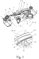
- Fig. 1
- die für die Erfindung wesentlichen Komponenten eines vorschlagsgemäßen Kraftfahrzeugschlosses in einer Draufsicht,
- Fig. 2
- das Kraftfahrzeugschloss gemäß
Fig. 1 im Funktionszustand "Entriegelt" in einer perspektivischen Unteransicht, - Fig. 3
- das Kraftfahrzeugschloss gemäß
Fig. 1 im Funktionszustand "Verriegelt" in einer perspektivischen Unteransicht und - Fig. 4
- das Kraftfahrzeugschloss gemäß
Fig. 1 a) im Funktionszustand "Entriegelt" und b) im Funktionszustand "Verriegelt", jeweils in einer Seitenansicht in Blickrichtung IV.
- Fig. 1
- the components of a proposed motor vehicle lock essential for the invention in a top view,
- Fig. 2
- the motor vehicle lock according to
Fig. 1 in the functional state "unlocked" in a perspective view from below, - Fig. 3
- the motor vehicle lock according to
Fig. 1 in the "Locked" functional state in a perspective bottom view and - Fig. 4
- the motor vehicle lock according to
Fig. 1 a) in the "Unlocked" functional state and b) in the "Locked" functional state, each in a side view in viewing direction IV.
In der Zeichnung sind nur diejenigen Komponenten dargestellt, die für die Erläuterung der Erfindung erforderlich sind. Entsprechend ist im Sinne einer hohen Übersichtlichkeit beispielsweise auf die Darstellung von Gehäuseteilen, von Lagerelementen o. dgl. verzichtet worden.In the drawing, only those components are shown which are necessary for explaining the invention. Accordingly, for the sake of greater clarity, housing parts, bearing elements or the like have not been shown.
Das dargestellte Kraftfahrzeugschloss ist mit den Schließelementen Schlossfalle 1 und Sperrklinke 2 ausgestattet, die in üblicher Weise zusammenwirken. Die Schlossfalle 1 lässt sich in eine Offenstellung (nicht dargestellt) und in eine in
Das Kraftfahrzeugschloss ist ferner mit einer Schlossmechanik 4 ausgestattet, die in verschiedene Funktionszustände bringbar ist. Bei diesen Funktionszuständen handelt es sich beispielsweise um die Funktionszustände "Entriegelt", "Verriegelt", "Kindergesichert" oder "Diebstahlgesichert". Die Bedeutung dieser Funktionszustände wurde im allgemeinen Teil der Beschreibung erläutert.The motor vehicle lock is also equipped with a lock mechanism 4 that can be brought into various functional states. These functional states are, for example, the functional states “unlocked”, “locked”, “child-proof” or “theft-proof”. The meaning of these functional states was explained in the general part of the description.
Das Kraftfahrzeugschloss weist einen Betätigungshebel 5 auf, dessen Betätigung in Abhängigkeit vom Funktionszustand der Schlossmechanik 4 ein Ausheben der Sperrklinke 2 bewirkt. Der Betätigungshebel 5 als solcher ist in der Explosionsdarstellung gemäß
Zur Einstellung zumindest eines Teils der Funktionszustände weist die Schlossmechanik 4 eine schaltbare Kupplungsanordnung 6 mit einem Kupplungselement 7 auf. Das Kupplungselement 7 lässt sich in eine Kuppelstellung (
Zur Verstellung des Kupplungselements 7 in Kuppelrichtung und in Entkuppelrichtung ist ein Verstellantrieb 8 vorgesehen, der hier und vorzugsweise als motorischer Verstellantrieb 8 ausgestaltet ist.To adjust the
In der Kraftwirkungskette 9 zwischen Verstellantrieb 8 und Kupplungselement 7, über die das Kupplungselement 7 hier und vorzugsweise motorisch verstellbar ist, ist vorschlagsgemäß eine Übertragungswippe 10 mit einer Wippenachse 11, einem antriebsseitigen Wippenarm 12 sowie einem kupplungselementseitigen Wippenarm 13 geschaltet. Dies bedeutet, dass die für die Verstellung des Kupplungselements 7 mittels des Verstellantriebs 8 erforderliche Antriebskraft über die Übertragungswippe 10 übertragen wird. Die hiermit verbundenen Vorteile wurden im allgemeinen Teil der Beschreibung erläutert.According to the proposal, a
Es lässt sich der Zeichnung entnehmen, dass sich die beiden Wippenarme 12, 13 der Übertragungswippe 10 von der Wippenachse 11 aus im Wesentlichen in entgegengesetzten Richtungen erstrecken. Insofern ist die Übertragungswippe 10 in erster Näherung nach Art einer klassischen Wippe ausgestaltet. Allerdings darf ausdrücklich darauf hingewiesen werden, dass eine gerade Ausgestaltung der Wippenarme 12, 13 für die vorschlagsgemäße Lösung nicht erforderlich ist. Auch dies lässt sich der Zeichnung entnehmen.It can be seen from the drawing that the two
Eine besonders kompakte Ausgestaltung ergibt sich hier dadurch, dass die Wippenachse 11 im Wesentlichen senkrecht zu der Betätigungshebelachse 14, der Sperrklinkenachse 15 und der Schlossfallenachse 16 ausgerichtet ist. Denkbar ist, dass die Wippenachse 11 senkrecht zu nur einer von Betätigungshebelachse 14, Sperrklinkenachse 15 und Schlossfallenachse 16 ausgerichtet ist.
Interessant bei dem dargestellten und insoweit bevorzugten Ausführungsbeispiel ist auch die Tatsache, dass die Betätigungshebelachse 14 identisch zu der Sperrklinkenachse 15 ist. Durch diese konstruktive Maßnahme lässt sich die Kompaktheit der Anordnung weiter steigern.The fact that the actuating lever axis 14 is identical to the ratchet axis 15 is also of interest in the exemplary embodiment illustrated and thus preferred. This structural measure allows the compactness of the arrangement to be increased further.
Wie ebenfalls weiter oben angedeutet, ist die Kupplungsanordnung 6 in die Kraftwirkungskette 17 zwischen dem Betätigungshebel 5 und der Sperrklinke 2 geschaltet. Damit lassen sich Betätigungshebel 5 und Sperrklinke 2 in Abhängigkeit von der Stellung des Kupplungselements 7 antriebstechnisch verbinden bzw. voneinander trennen.As also indicated further above, the clutch arrangement 6 is connected to the force-acting
Hier und vorzugsweise ist das Kupplungselement 7 selbst in die Kraftwirkungskette 17 zwischen dem Betätigungshebel 5 und der Sperrklinke 2 geschaltet. Dabei ist das Kupplungselement 7 weiter vorzugsweise zumindest abschnittsweise länglich ausgestaltet. Über diesen länglichen Abschnitt 18 des Kupplungselements 7 lassen sich auf besonders einfache Weise Kupplungskräfte übertragen, die im Wesentlichen senkrecht zu der Längserstreckung des länglichen Abschnitts 18 wirken. Die Richtung der Kupplungskräfte ist in
Für die Ausgestaltung des Kupplungselements 7 sind zahlreiche vorteilhafte Varianten denkbar. Bei dem dargestellten und insoweit bevorzugten Ausführungsbeispiel ist das Kupplungselement 7 als federelastisch biegbarer Draht oder Streifen ausgestaltet und so als Biege-Kupplungselement in die Kuppelstellung (
Hinsichtlich der Ausgestaltung des Kupplungselements 7 als federelastisch biegbarer Draht oder Streifen darf auf die internationale Patentanmeldung
Alternativ kann es vorgesehen sein, dass das Kupplungselement 7 in einem Teilbereich, vorzugsweise in einem Endbereich, des Kupplungselements 7 mittels einer nicht dargestellten Lageranordnung gelagert und dadurch in die Kuppelstellung und die Entkuppelstellung verstellbar ist. Im Einzelnen ist das Kupplungselement vorzugsweise so gelagert, dass das Kupplungselement 7 bezogen auf eine Referenzebene sowohl seitlich als auch in der Höhe, jeweils im Wesentlichen senkrecht zu seiner Längserstreckung, verstellbar ist. Hinsichtlich möglicher Ausgestaltungsvarianten eines solchen Kupplungselements 7 darf auf die internationale Patentanmeldung
Die Kupplungsfunktion der Kupplungsanordnung 6 ist bei dem vorliegenden Ausführungsbeispiel auf ganz besonders einfache Weise realisiert. In der Kuppelstellung ist das Kupplungselement 7 in kuppelnden Eingriff zwischen dem Betätigungshebel 5 und der Sperrklinke 2, hier einem mit der Sperrklinke 2 gekoppelten Sperrklinkenhebel 20, bringbar. Hierfür weist der Betätigungshebel 5 zwei Eingriffsflächen 21 und der Sperrklinkenhebel 20 eine Gegeneingriffsfläche 22 auf. Das in der Kuppelstellung befindliche Kupplungselement 7 befindet sich, wie in
In der Entkuppelstellung (
Bei dem dargestellten und insoweit bevorzugten Ausführungsbeispiel ist das Kupplungselement 7 in Richtung der Kuppelstellung (
Die Federvorspannung des Kupplungselements 7 auf den kupplungselementseitigen Wippenarm 13 geht hier und vorzugsweise in erster Linie auf seine eigene Federelastizität zurück. Damit kann auf eine separate Federanordnung grundsätzlich verzichtet werden. Alternativ oder zusätzlich kann es aber vorgesehen sein, dass die Federvorspannung des Kupplungselements 7 auf den kupplungselementseitigen Wippenarm 13 jedenfalls auch auf eine mit dem Kupplungselement 7 gekoppelte Federanordnung zurückgeht.The spring preload of the
Interessant bei dem dargestellten Ausführungsbeispiel ist weiter, dass sich das Kupplungselement 7 auf einem Eingriffsbereich 23 des kupplungselementseitigen Wippenarms 13 abstützt, so dass weiter vorzugsweise das Kupplungselement 7 durch seine eigene Federvorspannung im Ergebnis die Übertragungswippe 10 in Kuppelrichtung vorspannt. Die durch das Kupplungselement 7 verursachte Federvorspannung der Übertragungswippe 10 ist in den
Bei der oben beschriebenen, radialen Ausrichtung des länglichen Abschnitts 18 des Kupplungselements 7 ist es so, dass das Kupplungselement 7 einer Betätigung des Betätigungshebels 5 folgt. Dabei vollzieht das Kupplungselement 7 entsprechend eine kreisförmige Bewegung um die Betätigungshebelachse 14. Für den Fall, dass sich das Kupplungselement 7 auf der Übertragungswippe 10 abstützt, ist es für die Reduzierung der resultierenden Gleitreibung vorteilhaft, dass der kupplungselementseitige Wippenarm 13 jedenfalls im Eingriffsbereich 23 entlang eines Bogens 24, insbesondere eines Kreisbogens, um die Betätigungshebelachse 14 und hier auch die Sperrklinkenachse 15 bzw. die Sperrklinkenhebelachse herum verläuft. Dies ist am besten der Darstellung gemäß
Vorzugsweise ist ein nicht dargestellter Innenbetätigungshebel vorgesehen, der im montierten Zustand mit einem Türinnengriff gekoppelt ist. Weiter vorzugsweise ist ein nicht dargestellter Außenbetätigungshebel vorgesehen, der im montierten Zustand mit einem Türaußengriff gekoppelt ist. In besonders bevorzugter Ausgestaltung ist es so, dass der Innenbetätigungshebel und der Außenbetätigungshebel mit dem oben angesprochenen Betätigungshebel 5 gekoppelt sind. Denkbar ist auch, dass nur einer von Innenbetätigungshebel und Außenbetätigungshebel mit dem oben genannten Betätigungshebel 5 gekoppelt ist. Denkbar ist schließlich, dass es sich bei dem Betätigungshebel 5 bereits um den Innenbetätigungshebel oder den Außenbetätigungshebel handelt.An internal operating lever, not shown, is preferably provided which, in the assembled state, is coupled to an internal door handle. Furthermore, an external operating lever (not shown) is preferably provided, which is coupled to an external door handle in the assembled state. In a particularly preferred embodiment, the internal actuation lever and the external actuation lever are coupled to the
Zur Einstellung des Funktionszustands "Entriegelt" ist es nun vorgesehen, dass der Verstellantrieb 8 das Kupplungselement 7 über die Übertragungswippe 10 in die in
Zur Einstellung des Funktionszustands "Verriegelt" verstellt der Verstellantrieb 8 das Kupplungselement 7 über die Übertragungswippe 10 in die Entkuppelstellung (
Durch diese Entriegelung der Schlossmechanik 4 ist es dem Kupplungselement 7 spätestens nach einer zweiten Betätigung des Kupplungsbetätigungshebels 5 möglich, die Sperrklinke 2 über das dann in der Kuppelstellung befindliche Kupplungselement 7 auszuheben. Diese Funktion wird allgemein hin auch als "Doppelhub-Taxifunktion" bezeichnet.As a result of this unlocking of the lock mechanism 4, it is possible for the
Besonders interessant bei dem dargestellten Kraftfahrzeugschloss ist die Tatsache, dass sich der Funktionszustand "Diebstahlgesichert" besonders einfach realisieren lässt. Wie weiter oben erläutert, lässt sich im Funktionszustand "Diebstahlgesichert" die Sperrklinke 2 weder über den Innenbetätigungshebel noch über den Außenbetätigungshebel ausheben. Hier und vorzugsweise ist hierfür ein insbesondere motorischer Diebstahlsicherungsantrieb 26 vorgesehen, der zur Einstellung des Funktionszustands "Diebstahlgesichert" die Verstellung der Übertragungswippe 10 in Kuppelrichtung, in
Es ergibt sich aus der Darstellung gemäß
Es sind zahlreiche vorteilhafte Varianten für die Ausgestaltung der Übertragungswippe 10 denkbar. Hier und vorzugsweise ist die Übertragungswippe 10 aus Kunststoff ausgestaltet. Ein fertigungstechnisch einfacher Aufbau ergibt sich dadurch, dass die Übertragungswippe 10 einstückig ausgestaltet ist.Numerous advantageous variants for the configuration of the
Bei dem dargestellten und insoweit bevorzugten Ausführungsbeispiel ist die Übertragungswippe 10 in erster Näherung streifenförmig ausgebildet. Dies bedeutet, dass im Querschnitt gesehen die Breite b der Übertragungswippe 10 größer ist als die Höhe h, wodurch die Übertragungswippe 10 zwei sich über ihre Länge erstreckende Flachseiten und zwei sich über ihre Länge erstreckenden Schmalseiten aufweist. Die Wippenachse 11 erstreckt sich dabei im Wesentlichen parallel zu den Schmalseiten der Übertragungswippe 10.In the exemplary embodiment shown, which is preferred in this respect, the
Um die Gleiteigenschaften des Kupplungselements 7 auf dem kupplungselementseitigen Wippenarm 13 zu verbessern, ist zumindest der kupplungselementseitige Wippenarm 13 mit mindestens einer Kufe 27 ausgestattet, die senkrecht auf der dem Kupplungselement 7 zugewandten Flachseite der Ubertragungswippe 10 steht. Bei dem dargestellten und insoweit bevorzugten Ausführungsbeispiel sind beide Flachseiten der Übertragungswippe 10 jeweils beidseitig mit Kufen 27 ausgestattet, die nicht nur das obige Gleitverhalten verbessern, sondern der Übertragungswippe 10 auch eine hohe mechanische Stabilität verleihen. Damit ist es möglich, eine hohe mechanische Stabilität mit außerordentlich geringem Materialeinsatz zu gewährleisten.In order to improve the sliding properties of the
Es darf noch darauf hingewiesen werden, dass es vorteilhaft sein kann, mehrere, vorzugsweise zwei, vorschlagsgemäße Übertragungswippen 10 zu realisieren, denen jeweils ein Verstellantrieb zugeordnet ist. Damit lassen sich auch komplexe Funktionszustände mit einfachen Mitteln realisieren.It should also be pointed out that it can be advantageous to implement several, preferably two,
Es darf schließlich darauf hingewiesen werden, dass der obige Verstellantrieb 8 bei dem dargestellten Ausführungsbeispiel als Zentralverriegelungsantrieb ausgestaltet ist, um die Funktionszustände "Entriegelt" und "Verriegelt" zu realisieren. Für die Realisierung des Funktionszustands "Diebstahlgesichert" ist dann, wie oben erläutert, zusätzlich ein Diebstahlsicherungsantrieb vorgesehen.Finally, it should be pointed out that the
Grundsätzlich kann es aber vorgesehen sein, dass der Verstellantrieb 8 und die Übertragungswippe 10 in erster Linie oder ausschließlich der Einstellung des Funktionszustands "Diebstahlgesichert" dienen. Möglich wäre in diesem Zusammenhang auch, dass eine zusätzliche Übertragungswippe und ein zusätzlicher Verstellantrieb vorgesehen sind, um die Funktionszustände "Entriegelt" und "Verriegelt" zu realisieren. Auf die Möglichkeit der Realisierung mehrerer Übertragungswippen 10 wurde weiter oben bereits hingewiesen.In principle, however, it can be provided that the adjusting
Claims (15)
- Motor vehicle lock comprising a lock latch (1) and catch (2) as locking elements, and comprising a lock mechanism (4) which can be brought into different functional states, and comprising at least one actuating lever (5), the actuation of which, depending on the functional state of the lock mechanism (4), causes disengagement of the catch (2), wherein, in order to set at least some of the functional states, the lock mechanism (4) has a switchable coupling arrangement (6) with a coupling element (7) which can be brought at any rate into a coupling position and into a decoupling position, wherein an in particular motorized drive (8), in particular a central locking drive, is provided, by means of which the coupling element (7) is adjustable in the coupling direction and in the decoupling direction, characterized
in that a transmission rocker (10) having a rocker axis (11), a drive-side rocker arm (12) and a coupling-element-side rocker arm (13) is connected into the dynamic chain (9) between the adjustment drive (8) and the coupling element (7), and in that the coupling element (7) is spring-prestressed onto the coupling-element-side rocker arm (13) . - Motor vehicle lock according to Claim 1, characterized in that the rocker axis (11) is oriented substantially perpendicularly to the actuating lever axis (14) and/or to the catch axis (15) and/or to the lock latch axis (16), preferably in that the transmission rocker (10) extends past the catch axis (15) and the lock latch axis (16).
- Motor vehicle lock according to Claim 1 or 2, characterized in that the coupling arrangement (6), in particular the coupling element (7), is connected into the dynamic chain (17) between the actuating lever (5) and the catch (2), preferably in that the coupling element (7) is configured in elongate form at least in portions and in said portions transmits coupling forces acting substantially perpendicularly to its longitudinal extent.
- Motor vehicle lock according to one of the preceding claims, characterized in that the coupling element (7) is configured as a wire or strip which is bendable in a spring-elastic manner and therefore as a bending coupling element is bendable into the coupling position and the decoupling position, or in that the coupling element (7) is mounted in a partial region, in particular an end region, of the coupling element (7) by means of a bearing arrangement and is thereby adjustable into the coupling position and the decoupling position.
- Motor vehicle lock according to one of the preceding claims, characterized in that the coupling element (7) in the coupling position can be brought into coupling engagement between the actuating lever (5) and the catch (2) or a catch lever (20) coupled to the catch (2), and in that the coupling element (7) in the decoupling position is outside the range of movement of the actuating lever (5) and/or of the catch (2) or the catch lever (20).
- Motor vehicle lock according to one of the preceding claims, characterized in that the coupling element (7) is oriented with its elongate portion (18), which transmits the coupling forces, substantially radially with respect to the actuating lever axis (14) and/or catch axis (15) or catch lever axis.
- Motor vehicle lock according to one of the preceding claims, characterized in that the spring prestress of the coupling element (7) onto the coupling-element-side rocker arm (13) is at least partially attributed to its own spring elasticity, or in that the spring prestress of the coupling element (7) onto the coupling-element-side rocker arm (13) is at least partially attributed to a spring arrangement coupled to the coupling element (7) .
- Motor vehicle lock according to one of the preceding claims, characterized in that the coupling element (7) is supported on an engagement region (23) of the coupling-element-side rocker arm (13), preferably in that the coupling element (7) thereby spring-prestresses the transmission rocker (10).
- Motor vehicle lock according to one of the preceding claims, characterized in that the coupling-element-side rocker arm (13), at any rate in the engagement region (23) on which the coupling element (7) is supported, runs along an arc, in particular a circular arc, about the actuating lever axis (7) and/or catch axis (15) or catch lever axis.
- Motor vehicle lock according to one of the preceding claims, characterized in that the adjustment drive (8) has an engagement element (25) for the, in particular unidirectional, engagement in terms of drive with the drive-side rocker arm (12), preferably in that the engagement element (25) is configured as an eccentric, in particular as an eccentric disc.
- Motor vehicle lock according to one of the preceding claims, characterized in that an inside actuating lever is provided which, in the mounted state, is coupled to an inside door handle, and in that an outside actuating lever is provided which, in the mounted state, is coupled to an outside door handle, preferably in that the inside actuating lever and/or the outside actuating lever are or is coupled to the actuating lever (5).
- Motor vehicle lock according to one of the preceding claims, characterized in that the adjustment drive (8) adjusts the coupling element (7), via the transmission rocker (10), into the coupling position in order to set the "unlocked" functional state.
- Motor vehicle lock according to one of the preceding claims, characterized in that the adjustment drive (8) adjusts the coupling element (7), via the transmission rocker (10), into the decoupling position in order to set the "locked" functional state, and in that the adjustment drive (8) then, when the inside actuating lever is actuated, releases the transmission rocker (10) again in the coupling direction, preferably in that the inside actuating lever acts for this purpose on the adjustment drive (8).
- Motor vehicle lock according to one of the preceding claims, characterized in that an in particular motorized theft protection drive (26) is provided, and in that the theft protection drive (26) blocks the adjustment of the transmission rocker (10) in the coupling direction in order to set the "theft-protected" functional state.
- Motor vehicle lock according to one of the preceding claims, characterized in that the transmission rocker (10) is configured from plastic, preferably in that the transmission rocker (10) is formed integrally.
Applications Claiming Priority (1)
| Application Number | Priority Date | Filing Date | Title |
|---|---|---|---|
| DE202013004026.2U DE202013004026U1 (en) | 2013-04-30 | 2013-04-30 | Motor vehicle lock |
Publications (3)
| Publication Number | Publication Date |
|---|---|
| EP2799648A2 EP2799648A2 (en) | 2014-11-05 |
| EP2799648A3 EP2799648A3 (en) | 2015-07-29 |
| EP2799648B1 true EP2799648B1 (en) | 2020-10-07 |
Family
ID=50588585
Family Applications (1)
| Application Number | Title | Priority Date | Filing Date |
|---|---|---|---|
| EP14166605.7A Active EP2799648B1 (en) | 2013-04-30 | 2014-04-30 | Motor vehicle lock |
Country Status (2)
| Country | Link |
|---|---|
| EP (1) | EP2799648B1 (en) |
| DE (1) | DE202013004026U1 (en) |
Families Citing this family (1)
| Publication number | Priority date | Publication date | Assignee | Title |
|---|---|---|---|---|
| DE102020114902A1 (en) | 2020-06-04 | 2021-12-09 | Brose Schließsysteme GmbH & Co. Kommanditgesellschaft | Motor vehicle lock |
Citations (1)
| Publication number | Priority date | Publication date | Assignee | Title |
|---|---|---|---|---|
| DE19619849A1 (en) * | 1995-12-20 | 1997-07-03 | Vdo Schindling | Lock, esp for motor vehicle doors |
Family Cites Families (7)
| Publication number | Priority date | Publication date | Assignee | Title |
|---|---|---|---|---|
| DE19632781C2 (en) * | 1996-08-15 | 1998-08-27 | Kiekert Ag | Motor vehicle door lock with central locking system and anti-theft system |
| FR2871830A1 (en) * | 2004-06-18 | 2005-12-23 | Arvinmeritor Light Vehicle Sys | LOCK OF MOTOR VEHICLE |
| DE202004020037U1 (en) * | 2004-10-21 | 2006-03-02 | Brose Schließsysteme GmbH & Co.KG | Lock for motor vehicle has theft-proof lever, which is coupled with central locking lever such that displacement of central locking lever in closed position affects adjustment of theft-proof lever in theft-proof position |
| DE102008018500A1 (en) | 2007-09-21 | 2009-04-02 | BROSE SCHLIEßSYSTEME GMBH & CO. KG | Motor vehicle lock for use with controlling drive, has locking element of bolt, catch, and lock mechanism that is moved into different functional states, for e.g. unlocked, locked, anti-theft locked or child locked |
| DE202008012484U1 (en) | 2008-09-21 | 2010-02-18 | BROSE SCHLIEßSYSTEME GMBH & CO. KG | Motor vehicle lock |
| DE202010011539U1 (en) * | 2010-08-18 | 2011-12-13 | BROSE SCHLIEßSYSTEME GMBH & CO. KG | Motor vehicle lock |
| DE202011005608U1 (en) * | 2011-04-27 | 2013-06-18 | BROSE SCHLIEßSYSTEME GMBH & CO. KG | Motor vehicle lock |
-
2013
- 2013-04-30 DE DE202013004026.2U patent/DE202013004026U1/en not_active Expired - Lifetime
-
2014
- 2014-04-30 EP EP14166605.7A patent/EP2799648B1/en active Active
Patent Citations (1)
| Publication number | Priority date | Publication date | Assignee | Title |
|---|---|---|---|---|
| DE19619849A1 (en) * | 1995-12-20 | 1997-07-03 | Vdo Schindling | Lock, esp for motor vehicle doors |
Also Published As
| Publication number | Publication date |
|---|---|
| DE202013004026U1 (en) | 2014-08-01 |
| EP2799648A2 (en) | 2014-11-05 |
| EP2799648A3 (en) | 2015-07-29 |
Similar Documents
| Publication | Publication Date | Title |
|---|---|---|
| EP2342405B1 (en) | Motor vehicle lock | |
| EP2845972B1 (en) | Motor vehicle lock | |
| DE102008018500A1 (en) | Motor vehicle lock for use with controlling drive, has locking element of bolt, catch, and lock mechanism that is moved into different functional states, for e.g. unlocked, locked, anti-theft locked or child locked | |
| EP2420642B1 (en) | Motor vehicle lock | |
| DE19758078A1 (en) | Motor vehicle door lock | |
| WO2009149686A1 (en) | Closing device comprising a detent spring | |
| DE1653982A1 (en) | Doorknob mechanism | |
| EP0861960A2 (en) | Security lock | |
| DE102014106065A1 (en) | Motor vehicle lock | |
| EP3805493B1 (en) | Modular lock with panic function | |
| EP2199502B1 (en) | Motor vehicle lock | |
| DE102012111881A1 (en) | Motor operable stationary wing lock for double swing door, has trap ejector and latch ejector that are utilized for shifting terminal slider against opening direction of non-functional position that is brought into functional position | |
| EP2733286B1 (en) | Pivoting lever closure with low installation depth | |
| DE202008012536U1 (en) | Control drive for a motor vehicle lock | |
| EP2799648B1 (en) | Motor vehicle lock | |
| DE202007013330U1 (en) | Motor vehicle lock | |
| EP2784248B1 (en) | Drive unit for a fitting on a connecting rod | |
| DE2721979A1 (en) | Forked-catch lock for tractor door - has catch and ratchet plate on hollow sleeves with axial screws | |
| DE102013000286A1 (en) | Door lock device for a door with at least one door leaf | |
| DE1428501C3 (en) | Hood lock, in particular for motor vehicles | |
| DE202010008016U1 (en) | Lock bolt lock with improved safety | |
| EP1671001B1 (en) | Lock | |
| DE102005023224B4 (en) | Actuating device for the catch hook of a front hood | |
| WO2012119721A2 (en) | Furniture lock | |
| WO2019063755A1 (en) | Motor vehicle lock |
Legal Events
| Date | Code | Title | Description |
|---|---|---|---|
| PUAI | Public reference made under article 153(3) epc to a published international application that has entered the european phase |
Free format text: ORIGINAL CODE: 0009012 |
|
| 17P | Request for examination filed |
Effective date: 20140430 |
|
| AK | Designated contracting states |
Kind code of ref document: A2 Designated state(s): AL AT BE BG CH CY CZ DE DK EE ES FI FR GB GR HR HU IE IS IT LI LT LU LV MC MK MT NL NO PL PT RO RS SE SI SK SM TR |
|
| AX | Request for extension of the european patent |
Extension state: BA ME |
|
| RIN1 | Information on inventor provided before grant (corrected) |
Inventor name: ROSALES, DAVID Inventor name: JOSCHKO, ROMAN Inventor name: ZILLERT, MARKUS Inventor name: GRAUTE, LUDGER Inventor name: HAEGER, OLE |
|
| PUAL | Search report despatched |
Free format text: ORIGINAL CODE: 0009013 |
|
| AK | Designated contracting states |
Kind code of ref document: A3 Designated state(s): AL AT BE BG CH CY CZ DE DK EE ES FI FR GB GR HR HU IE IS IT LI LT LU LV MC MK MT NL NO PL PT RO RS SE SI SK SM TR |
|
| AX | Request for extension of the european patent |
Extension state: BA ME |
|
| RIC1 | Information provided on ipc code assigned before grant |
Ipc: E05B 85/26 20140101ALI20150624BHEP Ipc: E05B 15/04 20060101ALI20150624BHEP Ipc: E05B 81/16 20140101AFI20150624BHEP Ipc: E05B 81/36 20140101ALI20150624BHEP Ipc: E05B 81/06 20140101ALI20150624BHEP Ipc: E05B 77/28 20140101ALI20150624BHEP |
|
| R17P | Request for examination filed (corrected) |
Effective date: 20160129 |
|
| RBV | Designated contracting states (corrected) |
Designated state(s): AL AT BE BG CH CY CZ DE DK EE ES FI FR GB GR HR HU IE IS IT LI LT LU LV MC MK MT NL NO PL PT RO RS SE SI SK SM TR |
|
| STAA | Information on the status of an ep patent application or granted ep patent |
Free format text: STATUS: EXAMINATION IS IN PROGRESS |
|
| 17Q | First examination report despatched |
Effective date: 20180905 |
|
| GRAP | Despatch of communication of intention to grant a patent |
Free format text: ORIGINAL CODE: EPIDOSNIGR1 |
|
| STAA | Information on the status of an ep patent application or granted ep patent |
Free format text: STATUS: GRANT OF PATENT IS INTENDED |
|
| INTG | Intention to grant announced |
Effective date: 20200528 |
|
| GRAS | Grant fee paid |
Free format text: ORIGINAL CODE: EPIDOSNIGR3 |
|
| GRAA | (expected) grant |
Free format text: ORIGINAL CODE: 0009210 |
|
| STAA | Information on the status of an ep patent application or granted ep patent |
Free format text: STATUS: THE PATENT HAS BEEN GRANTED |
|
| AK | Designated contracting states |
Kind code of ref document: B1 Designated state(s): AL AT BE BG CH CY CZ DE DK EE ES FI FR GB GR HR HU IE IS IT LI LT LU LV MC MK MT NL NO PL PT RO RS SE SI SK SM TR |
|
| REG | Reference to a national code |
Ref country code: GB Ref legal event code: FG4D Free format text: NOT ENGLISH |
|
| REG | Reference to a national code |
Ref country code: CH Ref legal event code: EP Ref country code: AT Ref legal event code: REF Ref document number: 1321311 Country of ref document: AT Kind code of ref document: T Effective date: 20201015 |
|
| REG | Reference to a national code |
Ref country code: DE Ref legal event code: R096 Ref document number: 502014014838 Country of ref document: DE |
|
| REG | Reference to a national code |
Ref country code: IE Ref legal event code: FG4D Free format text: LANGUAGE OF EP DOCUMENT: GERMAN |
|
| REG | Reference to a national code |
Ref country code: NL Ref legal event code: MP Effective date: 20201007 |
|
| PG25 | Lapsed in a contracting state [announced via postgrant information from national office to epo] |
Ref country code: GR Free format text: LAPSE BECAUSE OF FAILURE TO SUBMIT A TRANSLATION OF THE DESCRIPTION OR TO PAY THE FEE WITHIN THE PRESCRIBED TIME-LIMIT Effective date: 20210108 Ref country code: FI Free format text: LAPSE BECAUSE OF FAILURE TO SUBMIT A TRANSLATION OF THE DESCRIPTION OR TO PAY THE FEE WITHIN THE PRESCRIBED TIME-LIMIT Effective date: 20201007 Ref country code: RS Free format text: LAPSE BECAUSE OF FAILURE TO SUBMIT A TRANSLATION OF THE DESCRIPTION OR TO PAY THE FEE WITHIN THE PRESCRIBED TIME-LIMIT Effective date: 20201007 Ref country code: NL Free format text: LAPSE BECAUSE OF FAILURE TO SUBMIT A TRANSLATION OF THE DESCRIPTION OR TO PAY THE FEE WITHIN THE PRESCRIBED TIME-LIMIT Effective date: 20201007 Ref country code: PT Free format text: LAPSE BECAUSE OF FAILURE TO SUBMIT A TRANSLATION OF THE DESCRIPTION OR TO PAY THE FEE WITHIN THE PRESCRIBED TIME-LIMIT Effective date: 20210208 Ref country code: NO Free format text: LAPSE BECAUSE OF FAILURE TO SUBMIT A TRANSLATION OF THE DESCRIPTION OR TO PAY THE FEE WITHIN THE PRESCRIBED TIME-LIMIT Effective date: 20210107 |
|
| REG | Reference to a national code |
Ref country code: LT Ref legal event code: MG4D |
|
| PG25 | Lapsed in a contracting state [announced via postgrant information from national office to epo] |
Ref country code: BG Free format text: LAPSE BECAUSE OF FAILURE TO SUBMIT A TRANSLATION OF THE DESCRIPTION OR TO PAY THE FEE WITHIN THE PRESCRIBED TIME-LIMIT Effective date: 20210107 Ref country code: ES Free format text: LAPSE BECAUSE OF FAILURE TO SUBMIT A TRANSLATION OF THE DESCRIPTION OR TO PAY THE FEE WITHIN THE PRESCRIBED TIME-LIMIT Effective date: 20201007 Ref country code: SE Free format text: LAPSE BECAUSE OF FAILURE TO SUBMIT A TRANSLATION OF THE DESCRIPTION OR TO PAY THE FEE WITHIN THE PRESCRIBED TIME-LIMIT Effective date: 20201007 Ref country code: LV Free format text: LAPSE BECAUSE OF FAILURE TO SUBMIT A TRANSLATION OF THE DESCRIPTION OR TO PAY THE FEE WITHIN THE PRESCRIBED TIME-LIMIT Effective date: 20201007 Ref country code: IS Free format text: LAPSE BECAUSE OF FAILURE TO SUBMIT A TRANSLATION OF THE DESCRIPTION OR TO PAY THE FEE WITHIN THE PRESCRIBED TIME-LIMIT Effective date: 20210207 Ref country code: PL Free format text: LAPSE BECAUSE OF FAILURE TO SUBMIT A TRANSLATION OF THE DESCRIPTION OR TO PAY THE FEE WITHIN THE PRESCRIBED TIME-LIMIT Effective date: 20201007 |
|
| PG25 | Lapsed in a contracting state [announced via postgrant information from national office to epo] |
Ref country code: HR Free format text: LAPSE BECAUSE OF FAILURE TO SUBMIT A TRANSLATION OF THE DESCRIPTION OR TO PAY THE FEE WITHIN THE PRESCRIBED TIME-LIMIT Effective date: 20201007 |
|
| REG | Reference to a national code |
Ref country code: DE Ref legal event code: R097 Ref document number: 502014014838 Country of ref document: DE |
|
| PG25 | Lapsed in a contracting state [announced via postgrant information from national office to epo] |
Ref country code: EE Free format text: LAPSE BECAUSE OF FAILURE TO SUBMIT A TRANSLATION OF THE DESCRIPTION OR TO PAY THE FEE WITHIN THE PRESCRIBED TIME-LIMIT Effective date: 20201007 Ref country code: RO Free format text: LAPSE BECAUSE OF FAILURE TO SUBMIT A TRANSLATION OF THE DESCRIPTION OR TO PAY THE FEE WITHIN THE PRESCRIBED TIME-LIMIT Effective date: 20201007 Ref country code: SK Free format text: LAPSE BECAUSE OF FAILURE TO SUBMIT A TRANSLATION OF THE DESCRIPTION OR TO PAY THE FEE WITHIN THE PRESCRIBED TIME-LIMIT Effective date: 20201007 Ref country code: LT Free format text: LAPSE BECAUSE OF FAILURE TO SUBMIT A TRANSLATION OF THE DESCRIPTION OR TO PAY THE FEE WITHIN THE PRESCRIBED TIME-LIMIT Effective date: 20201007 Ref country code: SM Free format text: LAPSE BECAUSE OF FAILURE TO SUBMIT A TRANSLATION OF THE DESCRIPTION OR TO PAY THE FEE WITHIN THE PRESCRIBED TIME-LIMIT Effective date: 20201007 |
|
| PLBE | No opposition filed within time limit |
Free format text: ORIGINAL CODE: 0009261 |
|
| STAA | Information on the status of an ep patent application or granted ep patent |
Free format text: STATUS: NO OPPOSITION FILED WITHIN TIME LIMIT |
|
| PG25 | Lapsed in a contracting state [announced via postgrant information from national office to epo] |
Ref country code: DK Free format text: LAPSE BECAUSE OF FAILURE TO SUBMIT A TRANSLATION OF THE DESCRIPTION OR TO PAY THE FEE WITHIN THE PRESCRIBED TIME-LIMIT Effective date: 20201007 |
|
| 26N | No opposition filed |
Effective date: 20210708 |
|
| PG25 | Lapsed in a contracting state [announced via postgrant information from national office to epo] |
Ref country code: AL Free format text: LAPSE BECAUSE OF FAILURE TO SUBMIT A TRANSLATION OF THE DESCRIPTION OR TO PAY THE FEE WITHIN THE PRESCRIBED TIME-LIMIT Effective date: 20201007 Ref country code: IT Free format text: LAPSE BECAUSE OF FAILURE TO SUBMIT A TRANSLATION OF THE DESCRIPTION OR TO PAY THE FEE WITHIN THE PRESCRIBED TIME-LIMIT Effective date: 20201007 |
|
| PG25 | Lapsed in a contracting state [announced via postgrant information from national office to epo] |
Ref country code: MC Free format text: LAPSE BECAUSE OF FAILURE TO SUBMIT A TRANSLATION OF THE DESCRIPTION OR TO PAY THE FEE WITHIN THE PRESCRIBED TIME-LIMIT Effective date: 20201007 Ref country code: SI Free format text: LAPSE BECAUSE OF FAILURE TO SUBMIT A TRANSLATION OF THE DESCRIPTION OR TO PAY THE FEE WITHIN THE PRESCRIBED TIME-LIMIT Effective date: 20201007 |
|
| PG25 | Lapsed in a contracting state [announced via postgrant information from national office to epo] |
Ref country code: LU Free format text: LAPSE BECAUSE OF NON-PAYMENT OF DUE FEES Effective date: 20210430 |
|
| REG | Reference to a national code |
Ref country code: BE Ref legal event code: MM Effective date: 20210430 |
|
| PG25 | Lapsed in a contracting state [announced via postgrant information from national office to epo] |
Ref country code: LI Free format text: LAPSE BECAUSE OF NON-PAYMENT OF DUE FEES Effective date: 20210430 Ref country code: CH Free format text: LAPSE BECAUSE OF NON-PAYMENT OF DUE FEES Effective date: 20210430 |
|
| PG25 | Lapsed in a contracting state [announced via postgrant information from national office to epo] |
Ref country code: IE Free format text: LAPSE BECAUSE OF NON-PAYMENT OF DUE FEES Effective date: 20210430 |
|
| PG25 | Lapsed in a contracting state [announced via postgrant information from national office to epo] |
Ref country code: IS Free format text: LAPSE BECAUSE OF FAILURE TO SUBMIT A TRANSLATION OF THE DESCRIPTION OR TO PAY THE FEE WITHIN THE PRESCRIBED TIME-LIMIT Effective date: 20210207 |
|
| REG | Reference to a national code |
Ref country code: AT Ref legal event code: MM01 Ref document number: 1321311 Country of ref document: AT Kind code of ref document: T Effective date: 20210430 |
|
| PG25 | Lapsed in a contracting state [announced via postgrant information from national office to epo] |
Ref country code: BE Free format text: LAPSE BECAUSE OF NON-PAYMENT OF DUE FEES Effective date: 20210430 |
|
| PG25 | Lapsed in a contracting state [announced via postgrant information from national office to epo] |
Ref country code: AT Free format text: LAPSE BECAUSE OF NON-PAYMENT OF DUE FEES Effective date: 20210430 |
|
| PGFP | Annual fee paid to national office [announced via postgrant information from national office to epo] |
Ref country code: FR Payment date: 20230309 Year of fee payment: 10 |
|
| PG25 | Lapsed in a contracting state [announced via postgrant information from national office to epo] |
Ref country code: HU Free format text: LAPSE BECAUSE OF FAILURE TO SUBMIT A TRANSLATION OF THE DESCRIPTION OR TO PAY THE FEE WITHIN THE PRESCRIBED TIME-LIMIT; INVALID AB INITIO Effective date: 20140430 |
|
| PGFP | Annual fee paid to national office [announced via postgrant information from national office to epo] |
Ref country code: GB Payment date: 20230309 Year of fee payment: 10 |
|
| PG25 | Lapsed in a contracting state [announced via postgrant information from national office to epo] |
Ref country code: CY Free format text: LAPSE BECAUSE OF FAILURE TO SUBMIT A TRANSLATION OF THE DESCRIPTION OR TO PAY THE FEE WITHIN THE PRESCRIBED TIME-LIMIT Effective date: 20201007 |
|
| PGFP | Annual fee paid to national office [announced via postgrant information from national office to epo] |
Ref country code: DE Payment date: 20230430 Year of fee payment: 10 Ref country code: CZ Payment date: 20230419 Year of fee payment: 10 |
|
| P01 | Opt-out of the competence of the unified patent court (upc) registered |
Effective date: 20230803 |
|
| PG25 | Lapsed in a contracting state [announced via postgrant information from national office to epo] |
Ref country code: MK Free format text: LAPSE BECAUSE OF FAILURE TO SUBMIT A TRANSLATION OF THE DESCRIPTION OR TO PAY THE FEE WITHIN THE PRESCRIBED TIME-LIMIT Effective date: 20201007 |
|
| PGFP | Annual fee paid to national office [announced via postgrant information from national office to epo] |
Ref country code: GB Payment date: 20240307 Year of fee payment: 11 |