EP2799521B1 - Microwave plasma biomass gasifying fixed bed gasifier and process - Google Patents
Microwave plasma biomass gasifying fixed bed gasifier and process Download PDFInfo
- Publication number
- EP2799521B1 EP2799521B1 EP12863868.1A EP12863868A EP2799521B1 EP 2799521 B1 EP2799521 B1 EP 2799521B1 EP 12863868 A EP12863868 A EP 12863868A EP 2799521 B1 EP2799521 B1 EP 2799521B1
- Authority
- EP
- European Patent Office
- Prior art keywords
- microwave plasma
- syngas
- furnace body
- vapor
- fixed bed
- Prior art date
- Legal status (The legal status is an assumption and is not a legal conclusion. Google has not performed a legal analysis and makes no representation as to the accuracy of the status listed.)
- Not-in-force
Links
- 239000002028 Biomass Substances 0.000 title claims description 24
- 238000000034 method Methods 0.000 title claims description 19
- QVGXLLKOCUKJST-UHFFFAOYSA-N atomic oxygen Chemical compound [O] QVGXLLKOCUKJST-UHFFFAOYSA-N 0.000 claims description 21
- 239000000446 fuel Substances 0.000 claims description 21
- 238000002309 gasification Methods 0.000 claims description 21
- 229910052760 oxygen Inorganic materials 0.000 claims description 21
- 239000001301 oxygen Substances 0.000 claims description 21
- 239000011269 tar Substances 0.000 claims description 16
- 239000002893 slag Substances 0.000 claims description 12
- 238000006243 chemical reaction Methods 0.000 claims description 11
- 238000012544 monitoring process Methods 0.000 claims description 11
- 239000007789 gas Substances 0.000 claims description 8
- 239000002699 waste material Substances 0.000 claims description 8
- 239000000463 material Substances 0.000 claims description 7
- UGFAIRIUMAVXCW-UHFFFAOYSA-N Carbon monoxide Chemical compound [O+]#[C-] UGFAIRIUMAVXCW-UHFFFAOYSA-N 0.000 claims description 6
- 239000003546 flue gas Substances 0.000 claims description 6
- 230000000694 effects Effects 0.000 claims description 5
- OKTJSMMVPCPJKN-UHFFFAOYSA-N Carbon Chemical group [C] OKTJSMMVPCPJKN-UHFFFAOYSA-N 0.000 claims description 4
- 239000000571 coke Substances 0.000 claims description 4
- 238000005336 cracking Methods 0.000 claims description 4
- 229930195733 hydrocarbon Natural products 0.000 claims description 4
- 150000002430 hydrocarbons Chemical class 0.000 claims description 4
- 239000007800 oxidant agent Substances 0.000 claims description 3
- 239000000126 substance Substances 0.000 claims description 3
- 238000007599 discharging Methods 0.000 claims description 2
- 238000012986 modification Methods 0.000 description 3
- 230000004048 modification Effects 0.000 description 3
- 239000002245 particle Substances 0.000 description 3
- 239000002910 solid waste Substances 0.000 description 3
- 230000015572 biosynthetic process Effects 0.000 description 2
- 238000005229 chemical vapour deposition Methods 0.000 description 2
- 239000006185 dispersion Substances 0.000 description 2
- 238000005516 engineering process Methods 0.000 description 2
- VNWKTOKETHGBQD-UHFFFAOYSA-N methane Chemical compound C VNWKTOKETHGBQD-UHFFFAOYSA-N 0.000 description 2
- 239000004215 Carbon black (E152) Substances 0.000 description 1
- 229920000742 Cotton Polymers 0.000 description 1
- 240000007594 Oryza sativa Species 0.000 description 1
- 235000007164 Oryza sativa Nutrition 0.000 description 1
- 230000010718 Oxidation Activity Effects 0.000 description 1
- 229910052799 carbon Inorganic materials 0.000 description 1
- 238000011109 contamination Methods 0.000 description 1
- 230000003247 decreasing effect Effects 0.000 description 1
- 230000007547 defect Effects 0.000 description 1
- 238000011161 development Methods 0.000 description 1
- 238000010586 diagram Methods 0.000 description 1
- 230000002708 enhancing effect Effects 0.000 description 1
- 230000007613 environmental effect Effects 0.000 description 1
- 238000005530 etching Methods 0.000 description 1
- 238000002474 experimental method Methods 0.000 description 1
- 239000002803 fossil fuel Substances 0.000 description 1
- 239000010903 husk Substances 0.000 description 1
- 238000009776 industrial production Methods 0.000 description 1
- 230000002401 inhibitory effect Effects 0.000 description 1
- 238000004519 manufacturing process Methods 0.000 description 1
- 238000003913 materials processing Methods 0.000 description 1
- 238000004377 microelectronic Methods 0.000 description 1
- 239000013307 optical fiber Substances 0.000 description 1
- 239000002861 polymer material Substances 0.000 description 1
- 238000002360 preparation method Methods 0.000 description 1
- 230000005855 radiation Effects 0.000 description 1
- 230000009257 reactivity Effects 0.000 description 1
- 235000009566 rice Nutrition 0.000 description 1
- 239000010902 straw Substances 0.000 description 1
- 238000003786 synthesis reaction Methods 0.000 description 1
Images
Classifications
-
- C—CHEMISTRY; METALLURGY
- C10—PETROLEUM, GAS OR COKE INDUSTRIES; TECHNICAL GASES CONTAINING CARBON MONOXIDE; FUELS; LUBRICANTS; PEAT
- C10J—PRODUCTION OF PRODUCER GAS, WATER-GAS, SYNTHESIS GAS FROM SOLID CARBONACEOUS MATERIAL, OR MIXTURES CONTAINING THESE GASES; CARBURETTING AIR OR OTHER GASES
- C10J3/00—Production of combustible gases containing carbon monoxide from solid carbonaceous fuels
- C10J3/72—Other features
-
- C—CHEMISTRY; METALLURGY
- C10—PETROLEUM, GAS OR COKE INDUSTRIES; TECHNICAL GASES CONTAINING CARBON MONOXIDE; FUELS; LUBRICANTS; PEAT
- C10J—PRODUCTION OF PRODUCER GAS, WATER-GAS, SYNTHESIS GAS FROM SOLID CARBONACEOUS MATERIAL, OR MIXTURES CONTAINING THESE GASES; CARBURETTING AIR OR OTHER GASES
- C10J3/00—Production of combustible gases containing carbon monoxide from solid carbonaceous fuels
- C10J3/02—Fixed-bed gasification of lump fuel
- C10J3/06—Continuous processes
-
- C—CHEMISTRY; METALLURGY
- C10—PETROLEUM, GAS OR COKE INDUSTRIES; TECHNICAL GASES CONTAINING CARBON MONOXIDE; FUELS; LUBRICANTS; PEAT
- C10J—PRODUCTION OF PRODUCER GAS, WATER-GAS, SYNTHESIS GAS FROM SOLID CARBONACEOUS MATERIAL, OR MIXTURES CONTAINING THESE GASES; CARBURETTING AIR OR OTHER GASES
- C10J3/00—Production of combustible gases containing carbon monoxide from solid carbonaceous fuels
- C10J3/02—Fixed-bed gasification of lump fuel
- C10J3/06—Continuous processes
- C10J3/18—Continuous processes using electricity
-
- C—CHEMISTRY; METALLURGY
- C10—PETROLEUM, GAS OR COKE INDUSTRIES; TECHNICAL GASES CONTAINING CARBON MONOXIDE; FUELS; LUBRICANTS; PEAT
- C10J—PRODUCTION OF PRODUCER GAS, WATER-GAS, SYNTHESIS GAS FROM SOLID CARBONACEOUS MATERIAL, OR MIXTURES CONTAINING THESE GASES; CARBURETTING AIR OR OTHER GASES
- C10J3/00—Production of combustible gases containing carbon monoxide from solid carbonaceous fuels
- C10J3/72—Other features
- C10J3/723—Controlling or regulating the gasification process
-
- C—CHEMISTRY; METALLURGY
- C10—PETROLEUM, GAS OR COKE INDUSTRIES; TECHNICAL GASES CONTAINING CARBON MONOXIDE; FUELS; LUBRICANTS; PEAT
- C10J—PRODUCTION OF PRODUCER GAS, WATER-GAS, SYNTHESIS GAS FROM SOLID CARBONACEOUS MATERIAL, OR MIXTURES CONTAINING THESE GASES; CARBURETTING AIR OR OTHER GASES
- C10J2300/00—Details of gasification processes
- C10J2300/09—Details of the feed, e.g. feeding of spent catalyst, inert gas or halogens
- C10J2300/0913—Carbonaceous raw material
- C10J2300/0916—Biomass
-
- C—CHEMISTRY; METALLURGY
- C10—PETROLEUM, GAS OR COKE INDUSTRIES; TECHNICAL GASES CONTAINING CARBON MONOXIDE; FUELS; LUBRICANTS; PEAT
- C10J—PRODUCTION OF PRODUCER GAS, WATER-GAS, SYNTHESIS GAS FROM SOLID CARBONACEOUS MATERIAL, OR MIXTURES CONTAINING THESE GASES; CARBURETTING AIR OR OTHER GASES
- C10J2300/00—Details of gasification processes
- C10J2300/09—Details of the feed, e.g. feeding of spent catalyst, inert gas or halogens
- C10J2300/0953—Gasifying agents
- C10J2300/0959—Oxygen
-
- C—CHEMISTRY; METALLURGY
- C10—PETROLEUM, GAS OR COKE INDUSTRIES; TECHNICAL GASES CONTAINING CARBON MONOXIDE; FUELS; LUBRICANTS; PEAT
- C10J—PRODUCTION OF PRODUCER GAS, WATER-GAS, SYNTHESIS GAS FROM SOLID CARBONACEOUS MATERIAL, OR MIXTURES CONTAINING THESE GASES; CARBURETTING AIR OR OTHER GASES
- C10J2300/00—Details of gasification processes
- C10J2300/09—Details of the feed, e.g. feeding of spent catalyst, inert gas or halogens
- C10J2300/0953—Gasifying agents
- C10J2300/0973—Water
- C10J2300/0976—Water as steam
-
- C—CHEMISTRY; METALLURGY
- C10—PETROLEUM, GAS OR COKE INDUSTRIES; TECHNICAL GASES CONTAINING CARBON MONOXIDE; FUELS; LUBRICANTS; PEAT
- C10J—PRODUCTION OF PRODUCER GAS, WATER-GAS, SYNTHESIS GAS FROM SOLID CARBONACEOUS MATERIAL, OR MIXTURES CONTAINING THESE GASES; CARBURETTING AIR OR OTHER GASES
- C10J2300/00—Details of gasification processes
- C10J2300/12—Heating the gasifier
- C10J2300/123—Heating the gasifier by electromagnetic waves, e.g. microwaves
- C10J2300/1238—Heating the gasifier by electromagnetic waves, e.g. microwaves by plasma
-
- C—CHEMISTRY; METALLURGY
- C10—PETROLEUM, GAS OR COKE INDUSTRIES; TECHNICAL GASES CONTAINING CARBON MONOXIDE; FUELS; LUBRICANTS; PEAT
- C10J—PRODUCTION OF PRODUCER GAS, WATER-GAS, SYNTHESIS GAS FROM SOLID CARBONACEOUS MATERIAL, OR MIXTURES CONTAINING THESE GASES; CARBURETTING AIR OR OTHER GASES
- C10J2300/00—Details of gasification processes
- C10J2300/12—Heating the gasifier
- C10J2300/1246—Heating the gasifier by external or indirect heating
-
- Y—GENERAL TAGGING OF NEW TECHNOLOGICAL DEVELOPMENTS; GENERAL TAGGING OF CROSS-SECTIONAL TECHNOLOGIES SPANNING OVER SEVERAL SECTIONS OF THE IPC; TECHNICAL SUBJECTS COVERED BY FORMER USPC CROSS-REFERENCE ART COLLECTIONS [XRACs] AND DIGESTS
- Y02—TECHNOLOGIES OR APPLICATIONS FOR MITIGATION OR ADAPTATION AGAINST CLIMATE CHANGE
- Y02P—CLIMATE CHANGE MITIGATION TECHNOLOGIES IN THE PRODUCTION OR PROCESSING OF GOODS
- Y02P20/00—Technologies relating to chemical industry
- Y02P20/10—Process efficiency
- Y02P20/129—Energy recovery, e.g. by cogeneration, H2recovery or pressure recovery turbines
-
- Y—GENERAL TAGGING OF NEW TECHNOLOGICAL DEVELOPMENTS; GENERAL TAGGING OF CROSS-SECTIONAL TECHNOLOGIES SPANNING OVER SEVERAL SECTIONS OF THE IPC; TECHNICAL SUBJECTS COVERED BY FORMER USPC CROSS-REFERENCE ART COLLECTIONS [XRACs] AND DIGESTS
- Y02—TECHNOLOGIES OR APPLICATIONS FOR MITIGATION OR ADAPTATION AGAINST CLIMATE CHANGE
- Y02P—CLIMATE CHANGE MITIGATION TECHNOLOGIES IN THE PRODUCTION OR PROCESSING OF GOODS
- Y02P20/00—Technologies relating to chemical industry
- Y02P20/141—Feedstock
- Y02P20/145—Feedstock the feedstock being materials of biological origin
Definitions
- the invention relates to the gasification of biomass and solid wastes, and more particularly to a gasifier and a method for gasifying biomass and solid wastes to synthesize high quality syngas in the presence of microwave plasma.
- China is rich in biomass resources including cotton stalks, straw, twigs, and rice husk.
- conventional primary energy sources such as fossil fuel are daily decreasing, people pay more and more attention to low calorific fuels.
- the fixed bed gasification has defects such as low gasification temperature, high tar content, and low-quality syngas.
- Low gasification temperature results in high content of tar in the syngas.
- the tar is difficult to remove and easily blocks and corrodes the valves, pipes, and auxiliary equipment.
- the removal of the tar costs much.
- microwave plasma with its own excellent characteristics, has widely applied to low temperature chemical vapor deposition gradually (CVD), rapid preparation of optical fibers, submicron etching of chips, surface modification of polymer materials, microelectronic materials processing, and so on.
- the invention adopts microwave and plasma to gasify biomass fuel with high efficiency, which provides a new way for the synthesis of syngas using biomass fuel and wastes.
- EP 2,163,597 A1 a method and apparatus is described for gasifying carbonic material, using microwave radiation to heat the carbonic material to generate plasma therein.
- a microwave plasma based fixed bed gasifier of biomass comprising a vertically disposed furnace body, a monitoring unit, and a microwave plasma generating device, the furnace body comprising a material and fuel inlet, a syngas outlet, an oxygen/vapor inlet, and a slag outlet, wherein the furnace body comprises a clearance zone in an upper part thereof and a fixed bed zone in a lower part thereof; the slag outlet is disposed at a bottom of the furnace body; the monitoring unit is disposed close to the syngas outlet; and at least one microwave plasma generating device is disposed on the furnace body.
- a first microwave plasma generating device is disposed between the fixed bed zone in the lower part of the furnace body and the material and fuel inlet, and a second microwave plasma generating device is disposed in the clearance zone in the upper part of the furnace body;
- the first microwave plasma generating device preferably comprises two or three layers of microwave plasma generators, the second microwave plasma generating device comprises one or two layers of microwave plasma generators, and each layer of the microwave plasma generators comprises three or four evenly distributed working gas inlets.
- the first microwave plasma generator has large power and small electrode gap, and produces high temperature of plasma; the second microwave plasma generator has large electrode gap, strong plasma activity, and wide volume range.
- a microwave power source of the microwave plasma generators has a basic frequency of 2.45 GHz, and a power of a single microwave plasma generator is within 200 kW.
- an upper oxygen/vapor nozzle is disposed in the clearance zone of the furnace body, and a lower oxygen/vapor nozzle is disposed in the fixed bed zone of the furnace body.
- a method of gasification using the gasifier comprises:
- the microwave-excited plasma oxidizer has high degree of ionization, high degree of dispersion, and strong oxidation activity and chemical reactivity. Thus, even in a relatively low ambient temperature, the chemical reaction can proceed.
- the conversion efficiency of the biomass fuel is high, and the syngas comprising CO and H 2 has high quality and little tars.
- step 1) the gasification temperature is between 700 and 1600°C; and in step 4), the temperature of the syngas is within 1200°C.
- step 1) the gasification temperature is between 750 and 950°C.
- step 1) the vapor sprayed from the lower oxygen/vapor nozzle operates to increase the vapor concentration thereby prompting the reaction between the carbon residues and the vapor; in step 2), a total power of the second microwave plasma generator meets the requirement for supplying thermal energy for the reaction equilibrium; in step 2), the appropriate high temperature vapor is sprayed from the upper oxygen/vapor nozzle to prompt the cracking reaction of the tars.
- a furnace body 2 is a vertically disposed cylinder, a clearance zone 8 is disposed at the uppermost of the furnace body, and a fixed bed zone receiving microwave plasma is disposed at the lowermost of the furnace body.
- a vertical downward slag outlet 7 is disposed at a bottom of the furnace body.
- An upper oxygen/vapor nozzle 5 is disposed in the clearance zone 8 of the furnace body, and a lower oxygen/vapor nozzle 4 is disposed in the fixed bed zone of the furnace body. Both the nozzles can be controlled by switches to regulate the flow rate.
- the furnace body 2 is cylindrical, or a combination of a cone and a cylinder.
- a feeder 1 is disposed in the middle of the furnace body 2 and communicates with the furnace body 2 via an inclined feeding chute.
- the feeding mode can optionally be screw feeding, without the need of the inclined feeding chute.
- the number of the microwave plasma generator is determined by the content of moisture and volatile components in the biomass fuel.
- the first microwave plasma generating device comprises two or three layers of microwave plasma generators 3 (in FIG. 1 , there are two layers of microwave plasma generators), which are centrally disposed below the feeder 1 and slightly higher than the bed material position in the fixed bed, and each layer of the microwave plasma generators comprises three or four evenly distributed working gas inlets.
- the similar arrangement of the microwave plasma generators such as being disposed above the feeder is also acceptable.
- the second microwave plasma generating device is disposed in the clearance zone which is above the feeder 1, and comprises one or two layers of microwave plasma generators, each layer of the microwave plasma generators comprises three or four evenly distributed working gas inlets (in FIG. 2 , there are three working gas inlets).
- the first microwave plasma generator 3 has large power and small electrode gap, and produces high temperature of plasma; the second microwave plasma generator 3' has large electrode gap, strong plasma activity, and wide volume range, which is configured to crack the tars in the syngas, and to convert hydrocarbons such as methane in the syngas. Finally, the tar content in the syngas is reduced to meet the direct usage level in industry, and the hydrocarbon content is also reduced, which is conducive to the subsequent carbon removal.
- the microwave power source of the microwave plasma generators has a basic frequency of 2.45 GHz, and a power of a single microwave plasma generator is within 200 kW.
- the total power of the second microwave plasma generator meets the requirement for supplying thermal energy for the reaction equilibrium.
- a monitoring unit 6 is disposed close to the syngas outlet at the top of the furnace body 2 to monitor in real time the temperature and components of the syngas to maintain process parameters within a preset range.
- the biomass fuel and waste are fed into the furnace body 2 via the feeder 1 and gasified quickly in the fixed bed zone of the gasifier.
- the fuel particles are pyrolyzed under high temperature to yield a large amount of volatile components and semi-coke residues.
- the volatile components react with oxygen and vapor in the presence of high activity of plasma generated by the microwave plasma generator.
- To regulate the temperature of the fixed bed zone can ensure the smooth operation of the gasification process. If the furnace temperature is too low, the working gas such as oxygen should be complemented in large, and meanwhile the microwave power of the microwave plasma generator 3 and the flow rate of the working gas are adjusted accordingly, vice versa.
- the vapor sprayed from the lower oxygen/vapor nozzle 4 operates to increase the vapor concentration, thereby prompting the reaction between the carbon residues and the vapor, improving the yield of H 2 , inhibiting the formation of the tars in the reaction zone, and enhancing the quality of the syngas.
- the syngas flows upwards to the clearance zone and is cracked.
- the coke residues fall downwards to the fixed bed zone and release heat energy to maintain the temperature therein.
- the resulting slag is discharged from the slag outlet 7.
- the syngas is further cracked in the presence of high degree of ionization and high activity of plasma generated by the second microwave plasma generator.
- Appropriate high temperature vapour is sprayed from the upper oxygen/vapor nozzle 5 for further cracking the tars in the syngas.
- the tar content is greatly reduced, which is conducive to the subsequent application.
- the gasification temperature is between 700 and 1600°C; and the temperature of the syngas is within 1200°C.
- the gasification temperature is between 750 and 950°C.
- the key is to control the temperature of the entrained flow bed, and to regulate the oxygen flow rate, vapor flow rate, and microwave power.
- the monitoring unit disposed close to the syngas outlet can monitor the above parameters in real time, thereby controlling the gasification process by chain and by full automation and maintaining the operation stability of the gasifier.
Landscapes
- Chemical & Material Sciences (AREA)
- Engineering & Computer Science (AREA)
- Combustion & Propulsion (AREA)
- Oil, Petroleum & Natural Gas (AREA)
- Organic Chemistry (AREA)
- Processing Of Solid Wastes (AREA)
- Gasification And Melting Of Waste (AREA)
- Vertical, Hearth, Or Arc Furnaces (AREA)
Description
- The invention relates to the gasification of biomass and solid wastes, and more particularly to a gasifier and a method for gasifying biomass and solid wastes to synthesize high quality syngas in the presence of microwave plasma.
- China is rich in biomass resources including cotton stalks, straw, twigs, and rice husk. As conventional primary energy sources such as fossil fuel are daily decreasing, people pay more and more attention to low calorific fuels.
- Meanwhile, with the growing of environmental awareness, higher efficiency and lower contamination of high technology has gradually been adopted by industrial production.
- Currently, the fixed bed gasification has defects such as low gasification temperature, high tar content, and low-quality syngas. Low gasification temperature results in high content of tar in the syngas. The tar is difficult to remove and easily blocks and corrodes the valves, pipes, and auxiliary equipment. The removal of the tar costs much. With the development of microwave technology, microwave plasma, with its own excellent characteristics, has widely applied to low temperature chemical vapor deposition gradually (CVD), rapid preparation of optical fibers, submicron etching of chips, surface modification of polymer materials, microelectronic materials processing, and so on.
- The invention adopts microwave and plasma to gasify biomass fuel with high efficiency, which provides a new way for the synthesis of syngas using biomass fuel and wastes. In
EP 2,163,597 A1 , a method and apparatus is described for gasifying carbonic material, using microwave radiation to heat the carbonic material to generate plasma therein. - In view of the abovedescribed problems, it is one objective of the invention to provide a fixed bed gasifier and a method using the same for the gasification of biomass to synthesize high quality syngas, particularly to synthesize the syngas comprising CO and H2 with characteristics of economy and high efficiency.
- To achieve the above objective, the following technical schemes are adopted.
- A microwave plasma based fixed bed gasifier of biomass, comprising a vertically disposed furnace body, a monitoring unit, and a microwave plasma generating device, the furnace body comprising a material and fuel inlet, a syngas outlet, an oxygen/vapor inlet, and a slag outlet, wherein the furnace body comprises a clearance zone in an upper part thereof and a fixed bed zone in a lower part thereof; the slag outlet is disposed at a bottom of the furnace body; the monitoring unit is disposed close to the syngas outlet; and at least one microwave plasma generating device is disposed on the furnace body.
- A first microwave plasma generating device is disposed between the fixed bed zone in the lower part of the furnace body and the material and fuel inlet, and a second microwave plasma generating device is disposed in the clearance zone in the upper part of the furnace body; the first microwave plasma generating device preferably comprises two or three layers of microwave plasma generators, the second microwave plasma generating device comprises one or two layers of microwave plasma generators, and each layer of the microwave plasma generators comprises three or four evenly distributed working gas inlets.
- Preferably, the first microwave plasma generator has large power and small electrode gap, and produces high temperature of plasma; the second microwave plasma generator has large electrode gap, strong plasma activity, and wide volume range.
- Preferably, a microwave power source of the microwave plasma generators has a basic frequency of 2.45 GHz, and a power of a single microwave plasma generator is within 200 kW.
- Preferably, an upper oxygen/vapor nozzle is disposed in the clearance zone of the furnace body, and a lower oxygen/vapor nozzle is disposed in the fixed bed zone of the furnace body.
- A method of gasification using the gasifier comprises:
- 1) feeding biomass fuel and waste into the furnace body via a feeder, allowing the biomass fuel and waste to be combusted and gasified in the fixed bed zone to yield high temperature flue gas, allowing the flue gas to flow upward to exchange heat with newly-fed biomass fuel and waste in a feeding zone of the gasifier, and meanwhile allowing the flue gas to react with vapor sprayed from the lower oxygen/vapor nozzle and with a plasma oxidizer generated by the first microwave plasma generator to yield syngas, of which a chemical equation being: 2C + O2 = 2CO, C + H2O = CO + H2, a gasification temperature being between 700 and 1600°C;
- Within the temperature range, the microwave-excited plasma oxidizer has high degree of ionization, high degree of dispersion, and strong oxidation activity and chemical reactivity. Thus, even in a relatively low ambient temperature, the chemical reaction can proceed. The conversion efficiency of the biomass fuel is high, and the syngas comprising CO and H2 has high quality and little tars.
- 2) allowing the syngas to flow upward to the clearance zone, where tars in the syngas are cracked and hydrocarbons in the syngas are converted in the presence of plasma generated by the second microwave plasma generator;
- 3) allowing coke residues to fall downward to the fixed bed zone and release thermal energy to maintain the temperature of the fixed bed zone, and discharging slags from the slag outlet; and
- 4) monitoring in real time a temperature and components of the syngas by the monitoring unit disposed close to the syngas outlet to maintain process parameters within a preset range.
- In step 1), the gasification temperature is between 700 and 1600°C; and in step 4), the temperature of the syngas is within 1200°C.
- In step 1), the gasification temperature is between 750 and 950°C.
- In step 1), the vapor sprayed from the lower oxygen/vapor nozzle operates to increase the vapor concentration thereby prompting the reaction between the carbon residues and the vapor; in step 2), a total power of the second microwave plasma generator meets the requirement for supplying thermal energy for the reaction equilibrium; in step 2), the appropriate high temperature vapor is sprayed from the upper oxygen/vapor nozzle to prompt the cracking reaction of the tars.
- Advantages according to embodiments of the invention are summarized as follows.
- 1. In the presence of high degree of ionization and high degree of dispersion of microwave plasma, the biomass fuel in the gasifier is converted with high efficiency, and the cold gas efficiency is significantly improved compared to that in conventional gasification processes, exceeding 85%.
- 2. The microwave plasma generator disposed in the clearance zone of the gasifier facilitates the unbalance cracking of tars in the syngas, and thus the syngas contains little or no tars, which can be directly used in industry, with simple process and good economic efficiency.
- 3. The gasifier has no specific requirement on the particle size of biomass fuel, primary crushing can meet the requirement of particle size, and thus the production costs are low, with good economic efficiency.
-
-
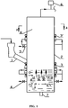
FIG. 1 shows a schematic diagram of a fixed bed gasifier of biomass and a flow chart of a gasification method using the same according to one embodiment of the invention. -
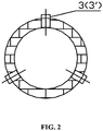
FIG. 2 is a sectional view taken from Line A-A ofFIG. 1 . - In the drawings, the following reference numbers are used: 1. Feeder; 2. Furnace body; 3. Microwave plasma generator; 4. Lower oxygen/vapor nozzle; 5. Upper oxygen/vapor nozzle; 6. Monitoring unit; 7. Slag outlet; 8. Clearance zone of gasifier.
- For further illustrating the invention, experiments detailing a gasifier and a method for gasifying biomass and solid wastes to synthesize high quality syngas are described below. It should be noted that the following examples are intended to describe and not to limit the invention.
- A
furnace body 2 is a vertically disposed cylinder, aclearance zone 8 is disposed at the uppermost of the furnace body, and a fixed bed zone receiving microwave plasma is disposed at the lowermost of the furnace body. A verticaldownward slag outlet 7 is disposed at a bottom of the furnace body. An upper oxygen/vapor nozzle 5 is disposed in theclearance zone 8 of the furnace body, and a lower oxygen/vapor nozzle 4 is disposed in the fixed bed zone of the furnace body. Both the nozzles can be controlled by switches to regulate the flow rate. Thefurnace body 2 is cylindrical, or a combination of a cone and a cylinder. - A
feeder 1 is disposed in the middle of thefurnace body 2 and communicates with thefurnace body 2 via an inclined feeding chute. The feeding mode can optionally be screw feeding, without the need of the inclined feeding chute. - The number of the microwave plasma generator is determined by the content of moisture and volatile components in the biomass fuel. As the biomass fuel contains high content of moisture (about 20%) and low caloric value, in this example, the first microwave plasma generating device comprises two or three layers of microwave plasma generators 3 (in
FIG. 1 , there are two layers of microwave plasma generators), which are centrally disposed below thefeeder 1 and slightly higher than the bed material position in the fixed bed, and each layer of the microwave plasma generators comprises three or four evenly distributed working gas inlets. The similar arrangement of the microwave plasma generators such as being disposed above the feeder is also acceptable. The second microwave plasma generating device is disposed in the clearance zone which is above thefeeder 1, and comprises one or two layers of microwave plasma generators, each layer of the microwave plasma generators comprises three or four evenly distributed working gas inlets (inFIG. 2 , there are three working gas inlets). - The first
microwave plasma generator 3 has large power and small electrode gap, and produces high temperature of plasma; the second microwave plasma generator 3' has large electrode gap, strong plasma activity, and wide volume range, which is configured to crack the tars in the syngas, and to convert hydrocarbons such as methane in the syngas. Finally, the tar content in the syngas is reduced to meet the direct usage level in industry, and the hydrocarbon content is also reduced, which is conducive to the subsequent carbon removal. - The microwave power source of the microwave plasma generators has a basic frequency of 2.45 GHz, and a power of a single microwave plasma generator is within 200 kW.
- The total power of the second microwave plasma generator meets the requirement for supplying thermal energy for the reaction equilibrium.
- A
monitoring unit 6 is disposed close to the syngas outlet at the top of thefurnace body 2 to monitor in real time the temperature and components of the syngas to maintain process parameters within a preset range. - The biomass fuel and waste are fed into the
furnace body 2 via thefeeder 1 and gasified quickly in the fixed bed zone of the gasifier. Firstly, the fuel particles are pyrolyzed under high temperature to yield a large amount of volatile components and semi-coke residues. The volatile components react with oxygen and vapor in the presence of high activity of plasma generated by the microwave plasma generator. To regulate the temperature of the fixed bed zone can ensure the smooth operation of the gasification process. If the furnace temperature is too low, the working gas such as oxygen should be complemented in large, and meanwhile the microwave power of themicrowave plasma generator 3 and the flow rate of the working gas are adjusted accordingly, vice versa. The vapor sprayed from the lower oxygen/vapor nozzle 4 operates to increase the vapor concentration, thereby prompting the reaction between the carbon residues and the vapor, improving the yield of H2, inhibiting the formation of the tars in the reaction zone, and enhancing the quality of the syngas. - With the feeding and gasification of the biomass fuel, the syngas flows upwards to the clearance zone and is cracked. The coke residues fall downwards to the fixed bed zone and release heat energy to maintain the temperature therein. The resulting slag is discharged from the
slag outlet 7. In theclearance zone 8, the syngas is further cracked in the presence of high degree of ionization and high activity of plasma generated by the second microwave plasma generator. Appropriate high temperature vapour is sprayed from the upper oxygen/vapor nozzle 5 for further cracking the tars in the syngas. Thus, the tar content is greatly reduced, which is conducive to the subsequent application. - The gasification temperature is between 700 and 1600°C; and the temperature of the syngas is within 1200°C. The gasification temperature is between 750 and 950°C.
- To achieve the optimal working conditions and satisfy the overall performance requirement of the gasification, the key is to control the temperature of the entrained flow bed, and to regulate the oxygen flow rate, vapor flow rate, and microwave power. The monitoring unit disposed close to the syngas outlet can monitor the above parameters in real time, thereby controlling the gasification process by chain and by full automation and maintaining the operation stability of the gasifier.
- While particular embodiments of the invention have been shown and described, it will be obvious to those skilled in the art that changes and modifications may be made without departing from the invention in its broader aspects, and therefore, the aim in the appended claims is to cover all such changes and modifications as fall within the true spirit and scope of the invention.
Claims (9)
- A microwave plasma based fixed bed gasifier of biomass, comprising a vertically disposed furnace body (2), a monitoring unit (6), and a microwave plasma generating device (3), the furnace body (2) comprising a material and fuel inlet, a syngas outlet, an oxygen/vapor inlet (4,5), and a slag outlet (7), wherein the furnace body (2) comprises a clearance zone (8) in an upper part thereof and a fixed bed zone in a lower part thereof; the slag outlet (7) is disposed at a bottom of the furnace body (2); the monitoring unit (6) is disposed close to the syngas outlet; at least one microwave plasma generating device (3) is disposed on the furnace body (2), a first microwave plasma generating device (3) is disposed between the fixed bed zone in the lower part of the furnace body (2) and the material and fuel inlet, and a second microwave plasma generating device (3') is disposed in the clearance zone (8) in the upper part of the furnace body (2).
- The gasifier of claim 1, characterized in that the first microwave plasma generating device (3) comprises two or three layers of microwave plasma generators, the second microwave plasma generating device (3') comprises one or two layers of microwave plasma generators, and each layer of the microwave plasma generators comprises three or four evenly distributed working gas inlets.
- The gasifier of claim 2, characterized in that the first microwave plasma generator (3) has large power and small electrode gap, and produces high temperature of plasma; the second microwave plasma generator (3') has large electrode gap, strong plasma activity, and wide volume range.
- The gasifier of claim 3, characterized in that a microwave power source of the microwave plasma generators (3, 3') has a basic frequency of 2.45 GHz, and a power of a single microwave plasma generator is within 200 kW.
- The gasifier of any one of claims 1-4, characterized in that an upper oxygen/vapor nozzle (5) is disposed in the clearance zone (8) of the furnace body (2), and a lower oxygen/vapor nozzle (4) is disposed in the fixed bed zone of the furnace body (2).
- A method of gasification using the gasifier of any one of preceding claims, the method comprising:1) feeding biomass fuel and waste into the furnace body (2) via a feeder, allowing the biomass fuel and waste to be combusted and gasified in the fixed bed zone to yield high temperature flue gas, allowing the flue gas to flow upward to exchange heat with newly-fed biomass fuel and waste in a feeding zone of the gasifier, and meanwhile allowing the flue gas to react with vapor sprayed from the lower oxygen/vapor nozzle (4, 5) and with a plasma oxidizer generated by the first microwave plasma generator (3) to yield syngas, of which a chemical equation being: 2C + O2 = 2CO, C + H2O = CO + H2, a gasification temperature being between 700 and 1600°C;2) allowing the syngas to flow upward to the clearance zone (8), where tars in the syngas are cracked and hydrocarbons in the syngas are converted in the presence of plasma generated by the second microwave plasma generator (3');3) allowing coke residues to fall downward to the fixed bed zone and release thermal energy to maintain the temperature of the fixed bed zone, and discharging slags from the slag outlet (7); and4) monitoring in real time a temperature and components of the syngas by the monitoring unit (6) disposed close to the syngas outlet to maintain process parameters within a preset range.
- The method of claim 6, characterized in that in step 1), the gasification temperature is between 700 and 1600°C; and in step 4), the temperature of the syngas is within 1200°C.
- The method of claim 7, characterized in that in step 1), the gasification temperature is between 750 and 950°C.
- The method of claim 7 or 8, characterized in that in step 1), the vapor sprayed from the lower oxygen/vapor nozzle (4) operates to increase the vapor concentration thereby prompting the reaction between the carbon residues and the vapor; in step 2), a total power of the second microwave plasma generator (3') meets the requirement for supplying thermal energy for the reaction equilibrium; the appropriate high temperature vapor is sprayed from the upper oxygen/vapor nozzle (5) to prompt the cracking reaction of the tars.
Applications Claiming Priority (2)
| Application Number | Priority Date | Filing Date | Title |
|---|---|---|---|
| CN201110449459.6A CN102559273B (en) | 2011-12-29 | 2011-12-29 | A microwave plasma biomass gasification fixed-bed gasifier and its process |
| PCT/CN2012/083569 WO2013097534A1 (en) | 2011-12-29 | 2012-10-26 | Microwave plasma biomass gasifying fixed bed gasifier and process |
Publications (3)
| Publication Number | Publication Date |
|---|---|
| EP2799521A1 EP2799521A1 (en) | 2014-11-05 |
| EP2799521A4 EP2799521A4 (en) | 2015-09-16 |
| EP2799521B1 true EP2799521B1 (en) | 2018-12-12 |
Family
ID=46405899
Family Applications (1)
| Application Number | Title | Priority Date | Filing Date |
|---|---|---|---|
| EP12863868.1A Not-in-force EP2799521B1 (en) | 2011-12-29 | 2012-10-26 | Microwave plasma biomass gasifying fixed bed gasifier and process |
Country Status (16)
| Country | Link |
|---|---|
| US (1) | US10336955B2 (en) |
| EP (1) | EP2799521B1 (en) |
| JP (1) | JP5959027B2 (en) |
| KR (1) | KR101625152B1 (en) |
| CN (1) | CN102559273B (en) |
| AP (1) | AP2014007830A0 (en) |
| AU (1) | AU2012362085B2 (en) |
| BR (1) | BR112014016168B1 (en) |
| CA (1) | CA2861814A1 (en) |
| DK (1) | DK2799521T3 (en) |
| IN (1) | IN2014MN01477A (en) |
| MX (1) | MX358425B (en) |
| MY (1) | MY167884A (en) |
| SG (1) | SG11201403665YA (en) |
| WO (1) | WO2013097534A1 (en) |
| ZA (1) | ZA201405494B (en) |
Families Citing this family (24)
| Publication number | Priority date | Publication date | Assignee | Title |
|---|---|---|---|---|
| CN102559273B (en) * | 2011-12-29 | 2014-03-05 | 武汉凯迪工程技术研究总院有限公司 | A microwave plasma biomass gasification fixed-bed gasifier and its process |
| CN102530859B (en) * | 2011-12-29 | 2013-11-06 | 武汉凯迪工程技术研究总院有限公司 | External-heating-type microwave plasma gasification furnace and synthesis gas production method |
| CN102963866B (en) * | 2012-11-30 | 2015-01-21 | 安徽理工大学 | Method for preparing hydrogen-rich synthesis gas via biomass pyrolysis |
| CN103194263B (en) * | 2013-04-15 | 2015-12-09 | 西安市宝润实业发展有限公司 | A kind of device and method utilizing high temperature alternating current arc to prepare biomass synthesis gas |
| CN103666580B (en) * | 2013-11-29 | 2015-07-22 | 武汉凯迪工程技术研究总院有限公司 | Coupled biomass pressurized pyrolysis process and system |
| CN103666573B (en) * | 2013-12-06 | 2015-10-21 | 中国五环工程有限公司 | Pressurized gasification process and system for gasifying solid waste through plasma fixed bed |
| CN105586091B (en) * | 2014-10-22 | 2018-02-09 | 中国石油化工股份有限公司大连石油化工研究院 | A kind of biomass pyrogenation gasification method |
| AT518753A2 (en) * | 2016-06-13 | 2017-12-15 | Gs Gruber-Schmidt Gmbh | Gasification of biogenic substances in a shaft reactor using microwave plasma |
| IT201600100814A1 (en) * | 2016-10-07 | 2018-04-07 | Processi Innovativi S R L | Process and plant for the production of waste syngas, preferably industrial or municipal waste and related associated products. |
| KR101893802B1 (en) * | 2016-11-16 | 2018-08-31 | 한국에너지기술연구원 | Microwave Ignitor for Fixed Bed Gasifier |
| CN107185949A (en) * | 2017-06-14 | 2017-09-22 | 安徽华东光电技术研究所 | A kind of microwave plasma refuse disposal installation and its processing method |
| CN108410503B (en) * | 2018-04-03 | 2023-06-27 | 内蒙古科技大学 | Reflux type high-temperature fixed bed gasifier and process method thereof |
| CN108329951B (en) * | 2018-04-11 | 2023-10-03 | 西安嘉士源新能源有限公司 | Anaerobic feeder |
| CN109442422B (en) * | 2018-11-05 | 2019-12-13 | 安徽航天环境工程有限公司 | High-temperature microwave plasma generator and waste treatment system |
| CN110677973B (en) * | 2019-11-07 | 2025-03-07 | 成都智合芯电科技开发有限公司 | Microwave plasma waste solid cracking device |
| CN111701984A (en) * | 2020-06-27 | 2020-09-25 | 商洛市海蓝科技有限公司 | Oil field solid waste microwave degradation processing apparatus |
| CN115448560A (en) * | 2021-06-09 | 2022-12-09 | 陕西青朗万城环保科技有限公司 | Microwave combustion-supporting treatment method and control system thereof |
| CN115448561A (en) * | 2021-06-09 | 2022-12-09 | 陕西青朗万城环保科技有限公司 | Microwave pyrolysis treatment method and control system thereof |
| CN115466030B (en) * | 2021-06-11 | 2025-03-07 | 陕西青朗万城环保科技有限公司 | A microwave-enhanced rotary kiln oily sludge treatment system |
| CN113483329A (en) * | 2021-07-08 | 2021-10-08 | 陕西青朗万城环保科技有限公司 | Solid waste combustion treatment method and control system thereof |
| CN113483332A (en) * | 2021-07-09 | 2021-10-08 | 陕西青朗万城环保科技有限公司 | Method for treating electronic garbage through microwave pyrolysis and control system thereof |
| CN115681990A (en) * | 2021-07-28 | 2023-02-03 | 陕西青朗万城环保科技有限公司 | Microwave plasma solid waste treatment method and equipment |
| US11339337B1 (en) * | 2021-08-19 | 2022-05-24 | Aries Clean Technologies Llc | Elimination of poly- and perfluoro alkyl substances (PFAS) in a wastewater biosolids gasification process using a thermal oxidizer and hydrated lime injection |
| CN115851321A (en) * | 2022-12-27 | 2023-03-28 | 东北大学 | Direct-current electrode type fixed bed coal gasification electric energy storage system and method |
Family Cites Families (29)
| Publication number | Priority date | Publication date | Assignee | Title |
|---|---|---|---|---|
| US3948645A (en) * | 1973-04-30 | 1976-04-06 | Boliden Aktiebolag | Method of carrying out heat-requiring chemical and/or physical processes in a fluidized bed |
| FR2555392B1 (en) * | 1983-11-17 | 1986-08-22 | Air Liquide | PROCESS FOR HEAT TREATMENT, ESPECIALLY CUTTING, WITH A PLASMA JET |
| JPS63146400A (en) * | 1986-12-08 | 1988-06-18 | バブコツク日立株式会社 | Plasma torch |
| US5280757A (en) * | 1992-04-13 | 1994-01-25 | Carter George W | Municipal solid waste disposal process |
| JPH08236293A (en) * | 1994-10-26 | 1996-09-13 | Matsushita Electric Ind Co Ltd | Microwave plasma torch and plasma generation method |
| US7090707B1 (en) * | 1999-11-02 | 2006-08-15 | Barot Devendra T | Combustion chamber design for a quench gasifier |
| US9481584B2 (en) * | 2001-07-16 | 2016-11-01 | Foret Plasma Labs, Llc | System, method and apparatus for treating liquids with wave energy from plasma |
| JP2003147373A (en) * | 2001-11-13 | 2003-05-21 | Eco Technos:Kk | Gasification method of organic matter by plasma |
| US7279655B2 (en) * | 2003-06-11 | 2007-10-09 | Plasmet Corporation | Inductively coupled plasma/partial oxidation reformation of carbonaceous compounds to produce fuel for energy production |
| WO2006081661A1 (en) * | 2005-02-04 | 2006-08-10 | Plasco Energy Group Inc. | Coal gasification process and apparatus |
| RU2007146272A (en) * | 2005-06-03 | 2009-06-20 | Пласко Энерджи Групп Инк., (CA) | SYSTEM FOR PROCESSING COAL IN GAS OF A SPECIFIC COMPOSITION |
| JP2008545840A (en) * | 2005-06-03 | 2008-12-18 | プラスコ エナジー グループ インコーポレイテッド | A system for converting carbonaceous feedstock to gas of specific composition |
| MX2008014199A (en) * | 2006-05-05 | 2009-09-07 | Plasco Energy Ip Holdings S L | A gas reformulating system using plasma torch heat. |
| NZ573217A (en) * | 2006-05-05 | 2011-11-25 | Plascoenergy Ip Holdings S L Bilbao Schaffhausen Branch | A facility for conversion of carbonaceous feedstock into a reformulated syngas containing CO and H2 |
| BRPI0711325A2 (en) * | 2006-05-05 | 2011-08-30 | Plascoenergy Ip Holdings S L Bilbao Schaffhausen Branch | control system for converting a carbonaceous feedstock into gas |
| US7752983B2 (en) * | 2006-06-16 | 2010-07-13 | Plasma Waste Recycling, Inc. | Method and apparatus for plasma gasification of waste materials |
| JP5547659B2 (en) * | 2007-02-27 | 2014-07-16 | プラスコエナジー アイピー ホールディングス、エス.エル.、ビルバオ、シャフハウゼン ブランチ | Gasification system with processing raw material / char conversion and gas reforming |
| US20080277265A1 (en) * | 2007-05-11 | 2008-11-13 | Plasco Energy Group, Inc. | Gas reformulation system comprising means to optimize the effectiveness of gas conversion |
| MX2007008317A (en) * | 2007-07-06 | 2009-02-26 | Aba Res Sa De Cv | Microwave gasification device. |
| US9074152B2 (en) * | 2007-09-12 | 2015-07-07 | General Electric Company | Plasma-assisted waste gasification system |
| EP2247347A4 (en) * | 2008-02-08 | 2013-08-14 | Peat International Inc | Method and apparatus of treating waste |
| CN201218507Y (en) * | 2008-05-29 | 2009-04-08 | 周开根 | Plasma and calcium oxide cooperation-gasified rubbish biomass gasification equipment |
| CN201530806U (en) * | 2009-08-24 | 2010-07-21 | 武汉凯迪控股投资有限公司 | Dual-cavity biomass gasification furnace |
| CN201530809U (en) * | 2009-09-22 | 2010-07-21 | 武汉凯迪控股投资有限公司 | Two-stage-plasma high temperature gasification equipment |
| CN101671578B (en) * | 2009-09-22 | 2012-11-21 | 武汉凯迪控股投资有限公司 | Combustible material plasma high-temperature gasification technique and equipment thereof |
| US20110290637A1 (en) * | 2010-05-28 | 2011-12-01 | General Electric Company | Sensing and control for plasma-assisted waste gasification |
| CN101906325B (en) * | 2010-07-20 | 2013-09-04 | 阳光凯迪新能源集团有限公司 | Process and apparatus thereof for low-temperature cracking and high-temperature gasification of biomass |
| CN202465606U (en) * | 2011-12-29 | 2012-10-03 | 武汉凯迪工程技术研究总院有限公司 | Microwave plasma biomass gasification fixed bed gasifier |
| CN102559273B (en) * | 2011-12-29 | 2014-03-05 | 武汉凯迪工程技术研究总院有限公司 | A microwave plasma biomass gasification fixed-bed gasifier and its process |
-
2011
- 2011-12-29 CN CN201110449459.6A patent/CN102559273B/en not_active Expired - Fee Related
-
2012
- 2012-10-26 EP EP12863868.1A patent/EP2799521B1/en not_active Not-in-force
- 2012-10-26 IN IN1477MUN2014 patent/IN2014MN01477A/en unknown
- 2012-10-26 SG SG11201403665YA patent/SG11201403665YA/en unknown
- 2012-10-26 KR KR1020147020553A patent/KR101625152B1/en not_active Expired - Fee Related
- 2012-10-26 WO PCT/CN2012/083569 patent/WO2013097534A1/en not_active Ceased
- 2012-10-26 BR BR112014016168A patent/BR112014016168B1/en not_active IP Right Cessation
- 2012-10-26 AP AP2014007830A patent/AP2014007830A0/en unknown
- 2012-10-26 JP JP2014549318A patent/JP5959027B2/en not_active Expired - Fee Related
- 2012-10-26 MY MYPI2014001928A patent/MY167884A/en unknown
- 2012-10-26 AU AU2012362085A patent/AU2012362085B2/en not_active Ceased
- 2012-10-26 MX MX2014007805A patent/MX358425B/en active IP Right Grant
- 2012-10-26 CA CA2861814A patent/CA2861814A1/en not_active Abandoned
- 2012-10-26 DK DK12863868.1T patent/DK2799521T3/en active
-
2014
- 2014-06-25 US US14/315,313 patent/US10336955B2/en active Active
- 2014-07-25 ZA ZA2014/05494A patent/ZA201405494B/en unknown
Non-Patent Citations (1)
| Title |
|---|
| CONRADS H ET AL: "Plasma generation and plasma sources", PLASMA SOURCES SCIENCE AND TECHNOLOGY, INSTITUTE OF PHYSICS PUBLISHING, BRISTOL, GB, vol. 9, no. 4, 1 November 2000 (2000-11-01), pages 441 - 454, XP020069829, ISSN: 0963-0252, DOI: 10.1088/0963-0252/9/4/301 * |
Also Published As
| Publication number | Publication date |
|---|---|
| RU2014131269A (en) | 2016-02-20 |
| BR112014016168A2 (en) | 2017-07-04 |
| IN2014MN01477A (en) | 2015-04-17 |
| CN102559273B (en) | 2014-03-05 |
| JP2015511966A (en) | 2015-04-23 |
| EP2799521A1 (en) | 2014-11-05 |
| EP2799521A4 (en) | 2015-09-16 |
| SG11201403665YA (en) | 2014-10-30 |
| CN102559273A (en) | 2012-07-11 |
| DK2799521T3 (en) | 2019-04-01 |
| MY167884A (en) | 2018-09-26 |
| AP2014007830A0 (en) | 2014-07-31 |
| US20140306161A1 (en) | 2014-10-16 |
| MX358425B (en) | 2018-08-17 |
| WO2013097534A1 (en) | 2013-07-04 |
| JP5959027B2 (en) | 2016-08-02 |
| BR112014016168B1 (en) | 2020-01-21 |
| US10336955B2 (en) | 2019-07-02 |
| MX2014007805A (en) | 2015-03-20 |
| ZA201405494B (en) | 2015-10-28 |
| AU2012362085A1 (en) | 2014-08-21 |
| CA2861814A1 (en) | 2013-07-04 |
| KR101625152B1 (en) | 2016-05-27 |
| KR20140120311A (en) | 2014-10-13 |
| AU2012362085B2 (en) | 2016-06-16 |
Similar Documents
| Publication | Publication Date | Title |
|---|---|---|
| AU2012362085B2 (en) | Microwave plasma biomass gasifying fixed bed gasifier and process | |
| EP2799523B1 (en) | Externally heated microwave plasma gasifier and synthesis gas production method | |
| AU2012362083B2 (en) | Microwave plasma biomass entrained flow gasifier and process | |
| CZ2017802A3 (en) | A method of converting a carbonaceous material to a low tar synthesis gas | |
| WO2011063579A1 (en) | Biomass three-stage entrained flow bed using exhausted heat and gasification method | |
| Cheng et al. | Allothermal gasification of biomass using micron size biomass as external heat source | |
| CN202465606U (en) | Microwave plasma biomass gasification fixed bed gasifier | |
| RU2588211C2 (en) | Microwave plasma biomass gasifier with fixed layer and gasification method | |
| Çakan et al. | Evaluation of sugar beet waste in the production of hydrogen-rich gas | |
| CN202465607U (en) | External heating type microwave plasma gasification furnace | |
| CN113881462A (en) | Organic solid waste semi-in-situ carbon fixation gasification device and application thereof | |
| Lahijani et al. | Air gasification of palm empty fruit bunch in a fluidized bed gasifier using various bed materials | |
| CA3172343C (en) | Waste processing system | |
| JP2025508265A (en) | Fixed-bed gasifier |
Legal Events
| Date | Code | Title | Description |
|---|---|---|---|
| PUAI | Public reference made under article 153(3) epc to a published international application that has entered the european phase |
Free format text: ORIGINAL CODE: 0009012 |
|
| 17P | Request for examination filed |
Effective date: 20140729 |
|
| AK | Designated contracting states |
Kind code of ref document: A1 Designated state(s): AL AT BE BG CH CY CZ DE DK EE ES FI FR GB GR HR HU IE IS IT LI LT LU LV MC MK MT NL NO PL PT RO RS SE SI SK SM TR |
|
| DAX | Request for extension of the european patent (deleted) | ||
| RA4 | Supplementary search report drawn up and despatched (corrected) |
Effective date: 20150817 |
|
| RIC1 | Information provided on ipc code assigned before grant |
Ipc: C10J 3/06 20060101ALI20150811BHEP Ipc: C10J 3/18 20060101AFI20150811BHEP Ipc: C10J 3/20 20060101ALI20150811BHEP Ipc: C10J 3/26 20060101ALI20150811BHEP Ipc: C10J 3/72 20060101ALI20150811BHEP |
|
| STAA | Information on the status of an ep patent application or granted ep patent |
Free format text: STATUS: EXAMINATION IS IN PROGRESS |
|
| 17Q | First examination report despatched |
Effective date: 20170323 |
|
| GRAP | Despatch of communication of intention to grant a patent |
Free format text: ORIGINAL CODE: EPIDOSNIGR1 |
|
| STAA | Information on the status of an ep patent application or granted ep patent |
Free format text: STATUS: GRANT OF PATENT IS INTENDED |
|
| INTG | Intention to grant announced |
Effective date: 20180530 |
|
| GRAS | Grant fee paid |
Free format text: ORIGINAL CODE: EPIDOSNIGR3 |
|
| GRAA | (expected) grant |
Free format text: ORIGINAL CODE: 0009210 |
|
| STAA | Information on the status of an ep patent application or granted ep patent |
Free format text: STATUS: THE PATENT HAS BEEN GRANTED |
|
| AK | Designated contracting states |
Kind code of ref document: B1 Designated state(s): AL AT BE BG CH CY CZ DE DK EE ES FI FR GB GR HR HU IE IS IT LI LT LU LV MC MK MT NL NO PL PT RO RS SE SI SK SM TR |
|
| REG | Reference to a national code |
Ref country code: GB Ref legal event code: FG4D |
|
| REG | Reference to a national code |
Ref country code: CH Ref legal event code: EP |
|
| REG | Reference to a national code |
Ref country code: AT Ref legal event code: REF Ref document number: 1075959 Country of ref document: AT Kind code of ref document: T Effective date: 20181215 |
|
| REG | Reference to a national code |
Ref country code: DE Ref legal event code: R096 Ref document number: 602012054720 Country of ref document: DE |
|
| REG | Reference to a national code |
Ref country code: IE Ref legal event code: FG4D |
|
| REG | Reference to a national code |
Ref country code: CH Ref legal event code: NV Representative=s name: RENTSCH PARTNER AG, CH |
|
| REG | Reference to a national code |
Ref country code: DK Ref legal event code: T3 Effective date: 20190325 |
|
| REG | Reference to a national code |
Ref country code: SE Ref legal event code: TRGR |
|
| REG | Reference to a national code |
Ref country code: NL Ref legal event code: MP Effective date: 20181212 |
|
| REG | Reference to a national code |
Ref country code: LT Ref legal event code: MG4D |
|
| PG25 | Lapsed in a contracting state [announced via postgrant information from national office to epo] |
Ref country code: ES Free format text: LAPSE BECAUSE OF FAILURE TO SUBMIT A TRANSLATION OF THE DESCRIPTION OR TO PAY THE FEE WITHIN THE PRESCRIBED TIME-LIMIT Effective date: 20181212 Ref country code: LT Free format text: LAPSE BECAUSE OF FAILURE TO SUBMIT A TRANSLATION OF THE DESCRIPTION OR TO PAY THE FEE WITHIN THE PRESCRIBED TIME-LIMIT Effective date: 20181212 Ref country code: BG Free format text: LAPSE BECAUSE OF FAILURE TO SUBMIT A TRANSLATION OF THE DESCRIPTION OR TO PAY THE FEE WITHIN THE PRESCRIBED TIME-LIMIT Effective date: 20190312 Ref country code: NO Free format text: LAPSE BECAUSE OF FAILURE TO SUBMIT A TRANSLATION OF THE DESCRIPTION OR TO PAY THE FEE WITHIN THE PRESCRIBED TIME-LIMIT Effective date: 20190312 Ref country code: LV Free format text: LAPSE BECAUSE OF FAILURE TO SUBMIT A TRANSLATION OF THE DESCRIPTION OR TO PAY THE FEE WITHIN THE PRESCRIBED TIME-LIMIT Effective date: 20181212 Ref country code: HR Free format text: LAPSE BECAUSE OF FAILURE TO SUBMIT A TRANSLATION OF THE DESCRIPTION OR TO PAY THE FEE WITHIN THE PRESCRIBED TIME-LIMIT Effective date: 20181212 |
|
| REG | Reference to a national code |
Ref country code: AT Ref legal event code: MK05 Ref document number: 1075959 Country of ref document: AT Kind code of ref document: T Effective date: 20181212 |
|
| PG25 | Lapsed in a contracting state [announced via postgrant information from national office to epo] |
Ref country code: AL Free format text: LAPSE BECAUSE OF FAILURE TO SUBMIT A TRANSLATION OF THE DESCRIPTION OR TO PAY THE FEE WITHIN THE PRESCRIBED TIME-LIMIT Effective date: 20181212 Ref country code: GR Free format text: LAPSE BECAUSE OF FAILURE TO SUBMIT A TRANSLATION OF THE DESCRIPTION OR TO PAY THE FEE WITHIN THE PRESCRIBED TIME-LIMIT Effective date: 20190313 Ref country code: RS Free format text: LAPSE BECAUSE OF FAILURE TO SUBMIT A TRANSLATION OF THE DESCRIPTION OR TO PAY THE FEE WITHIN THE PRESCRIBED TIME-LIMIT Effective date: 20181212 |
|
| PG25 | Lapsed in a contracting state [announced via postgrant information from national office to epo] |
Ref country code: NL Free format text: LAPSE BECAUSE OF FAILURE TO SUBMIT A TRANSLATION OF THE DESCRIPTION OR TO PAY THE FEE WITHIN THE PRESCRIBED TIME-LIMIT Effective date: 20181212 |
|
| PG25 | Lapsed in a contracting state [announced via postgrant information from national office to epo] |
Ref country code: PT Free format text: LAPSE BECAUSE OF FAILURE TO SUBMIT A TRANSLATION OF THE DESCRIPTION OR TO PAY THE FEE WITHIN THE PRESCRIBED TIME-LIMIT Effective date: 20190412 Ref country code: CZ Free format text: LAPSE BECAUSE OF FAILURE TO SUBMIT A TRANSLATION OF THE DESCRIPTION OR TO PAY THE FEE WITHIN THE PRESCRIBED TIME-LIMIT Effective date: 20181212 Ref country code: PL Free format text: LAPSE BECAUSE OF FAILURE TO SUBMIT A TRANSLATION OF THE DESCRIPTION OR TO PAY THE FEE WITHIN THE PRESCRIBED TIME-LIMIT Effective date: 20181212 Ref country code: IT Free format text: LAPSE BECAUSE OF FAILURE TO SUBMIT A TRANSLATION OF THE DESCRIPTION OR TO PAY THE FEE WITHIN THE PRESCRIBED TIME-LIMIT Effective date: 20181212 |
|
| PG25 | Lapsed in a contracting state [announced via postgrant information from national office to epo] |
Ref country code: SM Free format text: LAPSE BECAUSE OF FAILURE TO SUBMIT A TRANSLATION OF THE DESCRIPTION OR TO PAY THE FEE WITHIN THE PRESCRIBED TIME-LIMIT Effective date: 20181212 Ref country code: IS Free format text: LAPSE BECAUSE OF FAILURE TO SUBMIT A TRANSLATION OF THE DESCRIPTION OR TO PAY THE FEE WITHIN THE PRESCRIBED TIME-LIMIT Effective date: 20190412 Ref country code: RO Free format text: LAPSE BECAUSE OF FAILURE TO SUBMIT A TRANSLATION OF THE DESCRIPTION OR TO PAY THE FEE WITHIN THE PRESCRIBED TIME-LIMIT Effective date: 20181212 Ref country code: EE Free format text: LAPSE BECAUSE OF FAILURE TO SUBMIT A TRANSLATION OF THE DESCRIPTION OR TO PAY THE FEE WITHIN THE PRESCRIBED TIME-LIMIT Effective date: 20181212 Ref country code: SK Free format text: LAPSE BECAUSE OF FAILURE TO SUBMIT A TRANSLATION OF THE DESCRIPTION OR TO PAY THE FEE WITHIN THE PRESCRIBED TIME-LIMIT Effective date: 20181212 |
|
| REG | Reference to a national code |
Ref country code: DE Ref legal event code: R097 Ref document number: 602012054720 Country of ref document: DE |
|
| PLBE | No opposition filed within time limit |
Free format text: ORIGINAL CODE: 0009261 |
|
| STAA | Information on the status of an ep patent application or granted ep patent |
Free format text: STATUS: NO OPPOSITION FILED WITHIN TIME LIMIT |
|
| PG25 | Lapsed in a contracting state [announced via postgrant information from national office to epo] |
Ref country code: AT Free format text: LAPSE BECAUSE OF FAILURE TO SUBMIT A TRANSLATION OF THE DESCRIPTION OR TO PAY THE FEE WITHIN THE PRESCRIBED TIME-LIMIT Effective date: 20181212 Ref country code: SI Free format text: LAPSE BECAUSE OF FAILURE TO SUBMIT A TRANSLATION OF THE DESCRIPTION OR TO PAY THE FEE WITHIN THE PRESCRIBED TIME-LIMIT Effective date: 20181212 |
|
| 26N | No opposition filed |
Effective date: 20190913 |
|
| PG25 | Lapsed in a contracting state [announced via postgrant information from national office to epo] |
Ref country code: TR Free format text: LAPSE BECAUSE OF FAILURE TO SUBMIT A TRANSLATION OF THE DESCRIPTION OR TO PAY THE FEE WITHIN THE PRESCRIBED TIME-LIMIT Effective date: 20181212 |
|
| REG | Reference to a national code |
Ref country code: DE Ref legal event code: R119 Ref document number: 602012054720 Country of ref document: DE |
|
| REG | Reference to a national code |
Ref country code: FI Ref legal event code: MAE |
|
| REG | Reference to a national code |
Ref country code: DK Ref legal event code: EBP Effective date: 20191031 |
|
| PG25 | Lapsed in a contracting state [announced via postgrant information from national office to epo] |
Ref country code: MC Free format text: LAPSE BECAUSE OF FAILURE TO SUBMIT A TRANSLATION OF THE DESCRIPTION OR TO PAY THE FEE WITHIN THE PRESCRIBED TIME-LIMIT Effective date: 20181212 |
|
| REG | Reference to a national code |
Ref country code: CH Ref legal event code: PL |
|
| PG25 | Lapsed in a contracting state [announced via postgrant information from national office to epo] |
Ref country code: LI Free format text: LAPSE BECAUSE OF NON-PAYMENT OF DUE FEES Effective date: 20191031 Ref country code: CH Free format text: LAPSE BECAUSE OF NON-PAYMENT OF DUE FEES Effective date: 20191031 Ref country code: LU Free format text: LAPSE BECAUSE OF NON-PAYMENT OF DUE FEES Effective date: 20191026 Ref country code: FI Free format text: LAPSE BECAUSE OF NON-PAYMENT OF DUE FEES Effective date: 20191026 Ref country code: DE Free format text: LAPSE BECAUSE OF NON-PAYMENT OF DUE FEES Effective date: 20200501 |
|
| REG | Reference to a national code |
Ref country code: BE Ref legal event code: MM Effective date: 20191031 |
|
| PG25 | Lapsed in a contracting state [announced via postgrant information from national office to epo] |
Ref country code: BE Free format text: LAPSE BECAUSE OF NON-PAYMENT OF DUE FEES Effective date: 20191031 Ref country code: SE Free format text: LAPSE BECAUSE OF NON-PAYMENT OF DUE FEES Effective date: 20191027 |
|
| GBPC | Gb: european patent ceased through non-payment of renewal fee |
Effective date: 20191026 |
|
| PG25 | Lapsed in a contracting state [announced via postgrant information from national office to epo] |
Ref country code: GB Free format text: LAPSE BECAUSE OF NON-PAYMENT OF DUE FEES Effective date: 20191026 Ref country code: FR Free format text: LAPSE BECAUSE OF NON-PAYMENT OF DUE FEES Effective date: 20191031 Ref country code: IE Free format text: LAPSE BECAUSE OF NON-PAYMENT OF DUE FEES Effective date: 20191026 Ref country code: DK Free format text: LAPSE BECAUSE OF NON-PAYMENT OF DUE FEES Effective date: 20191031 |
|
| PG25 | Lapsed in a contracting state [announced via postgrant information from national office to epo] |
Ref country code: CY Free format text: LAPSE BECAUSE OF FAILURE TO SUBMIT A TRANSLATION OF THE DESCRIPTION OR TO PAY THE FEE WITHIN THE PRESCRIBED TIME-LIMIT Effective date: 20181212 |
|
| PG25 | Lapsed in a contracting state [announced via postgrant information from national office to epo] |
Ref country code: HU Free format text: LAPSE BECAUSE OF FAILURE TO SUBMIT A TRANSLATION OF THE DESCRIPTION OR TO PAY THE FEE WITHIN THE PRESCRIBED TIME-LIMIT; INVALID AB INITIO Effective date: 20121026 Ref country code: MT Free format text: LAPSE BECAUSE OF FAILURE TO SUBMIT A TRANSLATION OF THE DESCRIPTION OR TO PAY THE FEE WITHIN THE PRESCRIBED TIME-LIMIT Effective date: 20181212 |
|
| PG25 | Lapsed in a contracting state [announced via postgrant information from national office to epo] |
Ref country code: MK Free format text: LAPSE BECAUSE OF FAILURE TO SUBMIT A TRANSLATION OF THE DESCRIPTION OR TO PAY THE FEE WITHIN THE PRESCRIBED TIME-LIMIT Effective date: 20181212 |