EP2798989A1 - Beverage preparation device with means for milk heating and operating procedure - Google Patents
Beverage preparation device with means for milk heating and operating procedure Download PDFInfo
- Publication number
- EP2798989A1 EP2798989A1 EP14166502.6A EP14166502A EP2798989A1 EP 2798989 A1 EP2798989 A1 EP 2798989A1 EP 14166502 A EP14166502 A EP 14166502A EP 2798989 A1 EP2798989 A1 EP 2798989A1
- Authority
- EP
- European Patent Office
- Prior art keywords
- milk
- steam
- line
- outlet opening
- phase
- Prior art date
- Legal status (The legal status is an assumption and is not a legal conclusion. Google has not performed a legal analysis and makes no representation as to the accuracy of the status listed.)
- Granted
Links
- 239000008267 milk Substances 0.000 title claims abstract description 179
- 210000004080 milk Anatomy 0.000 title claims abstract description 179
- 235000013336 milk Nutrition 0.000 title claims abstract description 179
- 238000010438 heat treatment Methods 0.000 title claims abstract description 39
- 238000002360 preparation method Methods 0.000 title claims abstract description 34
- 235000013361 beverage Nutrition 0.000 title claims abstract description 31
- 238000011017 operating method Methods 0.000 title 1
- XLYOFNOQVPJJNP-UHFFFAOYSA-N water Chemical compound O XLYOFNOQVPJJNP-UHFFFAOYSA-N 0.000 claims abstract description 80
- 239000012530 fluid Substances 0.000 claims abstract description 33
- 235000013353 coffee beverage Nutrition 0.000 claims abstract description 25
- 238000002386 leaching Methods 0.000 claims abstract description 4
- 239000008236 heating water Substances 0.000 claims abstract description 3
- 238000000034 method Methods 0.000 claims description 13
- 238000004140 cleaning Methods 0.000 claims description 11
- 238000005187 foaming Methods 0.000 claims description 6
- 239000000919 ceramic Substances 0.000 claims description 4
- 239000006260 foam Substances 0.000 claims description 3
- 238000009826 distribution Methods 0.000 claims description 2
- 238000010926 purge Methods 0.000 claims 1
- 238000004519 manufacturing process Methods 0.000 description 4
- 238000011161 development Methods 0.000 description 3
- 230000018109 developmental process Effects 0.000 description 3
- 238000009835 boiling Methods 0.000 description 2
- 239000008400 supply water Substances 0.000 description 2
- 238000007664 blowing Methods 0.000 description 1
- 235000015116 cappuccino Nutrition 0.000 description 1
- 238000010276 construction Methods 0.000 description 1
- 230000000694 effects Effects 0.000 description 1
- 239000000446 fuel Substances 0.000 description 1
- JEGUKCSWCFPDGT-UHFFFAOYSA-N h2o hydrate Chemical compound O.O JEGUKCSWCFPDGT-UHFFFAOYSA-N 0.000 description 1
- 235000020307 latte macchiato Nutrition 0.000 description 1
- 238000011144 upstream manufacturing Methods 0.000 description 1
Images


Classifications
-
- A—HUMAN NECESSITIES
- A47—FURNITURE; DOMESTIC ARTICLES OR APPLIANCES; COFFEE MILLS; SPICE MILLS; SUCTION CLEANERS IN GENERAL
- A47J—KITCHEN EQUIPMENT; COFFEE MILLS; SPICE MILLS; APPARATUS FOR MAKING BEVERAGES
- A47J31/00—Apparatus for making beverages
- A47J31/44—Parts or details or accessories of beverage-making apparatus
- A47J31/4485—Nozzles dispensing heated and foamed milk, i.e. milk is sucked from a milk container, heated and foamed inside the device, and subsequently dispensed from the nozzle
Definitions
- the invention relates to a beverage preparation device according to the preamble of claim 1, in particular in the form of a brewing unit comprising a coffee machine, with means for heating milk by means of steam, comprising a heater for heating water to form water vapor, with a via a motive steam line with vapor or For supplying steam generated fluid supplyable drive nozzle for generating negative pressure and thereby sucking milk through a milk line, wherein steam for heating the milk through an outlet opening of the motive nozzle in the sucked milk can be introduced bar. Furthermore, the invention relates to a method for operating a beverage preparation device according to the preamble of claim 11.
- a device for dispensing milk froth or heated milk wherein by means of a steam generator steam is generated, which can be fed to the milk flow exclusively alternatively via a steam line to a nozzle opening into a frothing chamber or a separate nozzle spaced therefrom.
- steam can be generated, which can be fed to the milk flow exclusively alternatively via a steam line to a nozzle opening into a frothing chamber or a separate nozzle spaced therefrom.
- the setting for supplying the opening into the foaming chamber nozzle is selected with steam, milk foam can be produced with the known device. If the steam supply path is selected via the alternative nozzle, non-foamed milk is heated by the steam.
- the known device has two water vapor channels, which are brought together before a position at which the water vapor is supplied to the milk. In other words, the steam supply into the milk takes place at a single position.
- the present invention seeks to further develop a generic beverage preparation device, in particular a coffee machine comprising a brewing unit for leaching coffee grounds that with this the milk temperature to a higher temperature level, in particular of about 50 ° C. can be heated, preferably without a larger one or to have to provide an additional heating device for heating the milk and preferably without having to accept a significant milk flow velocity. Furthermore, the object is to provide a correspondingly improved method for operating a beverage device with which higher milk temperatures than previously can be generated.
- the invention is based on the idea to bring the milk temperature thereby to a higher temperature level, that water vapor is fed not only through the, in particular single, outlet opening of the motive nozzle into the milk, but at the same time at least one further position in the flow direction of the milk before or after this outlet opening of the motive nozzle.
- the milk temperature can be increased surprisingly significantly, in particular to temperatures of more than 50 ° C., very particularly preferably above 55 ° C, even more preferably above 60 ° C, and most preferably to a temperature within a temperature range between about 58 ° C and 75 ° C.
- At least one additional steam line must be provided for this purpose, in addition to the fuel line supplying steam to the outlet opening of the motive nozzle, via which water vapor can be supplied to the milk.
- the motive nozzle has two outlet openings for steam, in which case the additional steam line would be formed by a section of the motive nozzle.
- the at least one additional steam line is adjacent, preferably spaced from the drive nozzle and adjacent to this, in particular spaced from this opens, in particular in the flow direction before or after the, in particular single, outlet opening of the motive nozzle.
- the additional steam line preferably has a restrictor (constriction point) at which fluid heated above the boiling temperature at atmospheric pressure can relax to steam.
- motive steam line and additional steam line are understood to be conveyed via these, in particular at the same time, vaporous or steam-generating fluid.
- the fluid in a possible embodiment within the motive steam line due to an overpressure (not yet) must be non-vaporous, but only a temperature must have, in particular of over 100 ° C, which ensures that from the heated fluid after a corresponding relaxation, in particular at a throttle, water vapor is formed.
- water vapor is transported directly through the motive steam line and / or at least one additional line.
- the outlet opening of the motive nozzle is followed by a chamber into which the milk drawn in through the milk line is mixed with the water vapor flowing out through the outlet opening of the motive nozzle.
- This chamber is used in a further development of the invention in a different from a Nursingerhitzungs GmbH sosShGrasSh for foaming the milk. During this AufMum AnlagensShes the milk, in particular in contrast to the pure Nursingerhitzungs Anlagensschreib no air is supplied via a possibly provided air supply line.
- the chamber preferably has an inner diameter which corresponds to a multiple inner diameter of the milk line.
- the beverage preparation device according to the invention is a beverage preparation device for domestic use, which usually no means, in particular proportional valves or ram devices or the like.
- the heating device dividing means in particular comprising a steam line branch (eg one, preferably via a manually or motor-driven valve openable or closable connection line or branch line between the motive steam line or an upstream common fluid line and the additional steam line) with which the fluid provided by the heater (water vapor or water heated above the boiling point at atmospheric pressure) can be divided into the motive steam line and the at least one additional steam line.
- a steam line branch eg one, preferably via a manually or motor-driven valve openable or closable connection line or branch line between the motive steam line or an upstream common fluid line and the additional steam line
- the fluid provided by the heater water vapor or water heated above the boiling point at atmospheric pressure
- the distribution of the fluid makes it possible to make better use of the amount of heat energy provided or adjustable by the heating device than is possible in the prior art.
- a significantly higher than in the past practice milk temperature can be achieved.
- the speed with which the milk is conveyed is obviously only slightly reduced or not at all reduced in comparison to a design with a steam feed line at the drive nozzle. Therefore, the further development solution has advantages against a conceivable variant in which a temperature increase is achieved by artificially lowering the milk rate at which the milk flows relative to the motive nozzle, in order to increase the amount of steam and thus the energy input per milk volume unit.
- the additional steam line is in an (optional) foaming operating state of the beverage preparation device in which (optional) the Outlet opening of the motive nozzle downstream chamber milk is frothable to milk froth, an air line through which air is supplied during the AufMum remplisShes the milk before it enters the chamber. It is particularly useful if this air line includes a throttle.
- the beverage preparation device in which the heating device is arranged downstream of a preferably ceramic, in particular electromotive, controllable multiway valve, by which the fluid provided by the heating device of at least one functional unit, in particular to the milk heating means, even more preferably can flow to the motive nozzle.
- the multi-way valve is connected such that with this the supply of a functional unit of beverage preparation device in a different Nursingerhitzungs Scsschreib operating state with air, especially for milk frothing and / or cleaning water and / or cleaning water vapor (cleaning mode) is controllable ,
- the above-mentioned multi-way valve is designed such that with this the provided by the heater fluid flow is divisible on the one leading to the motive nozzle motive steam line and on the other at least one additional steam line through the water vapor at the different from the outlet opening of the motive nozzle Position of the milk can be supplied.
- a valve separate from the multi-way valve may be provided for dividing this fluid.
- valve means of the dividing means which may optionally comprise the above-described multi-way valve and / or at least one additional (separate from a multi-way valve) or alternative valve, are manually or automatically operable such that during the milk heating process in a first phase Water vapor is fed exclusively via the motive steam line and thus via the outlet opening of the motive nozzle of the milk and in a second phase subsequent to this first phase additionally steam is fed via the at least one additional steam line of the milk.
- steam can additionally be supplied to the milk stream via the at least one additional steam line or, according to the alternative embodiment, the steam volume flow through the additional steam line can be increased.
- valve means it is particularly preferred, in particular for reasons of cost and to simplify the construction, to dispense with means for continuous adjustment of the fluid volume flow of the steam provided by the heating device or for the purpose of generating steam. In this case, it is then only possible to open or close a steam line by means of valve means, i. there are only two valve states - open, closed.
- the invention also leads to a method for operating a beverage preparation device, in particular for operating a coffee machine, in particular a coffee machine, the coffee machine then comprises a brewing unit for leaching coffee grounds.
- the device operated by the method according to the invention is preferably a beverage preparation device designed according to the concept of the invention.
- steam is supplied at at least two different positions of the milk, it being particularly preferred if the whole, which in the Milk introduced steam comes from a heater and is only divided accordingly. It is essential that a position through which water vapor is supplied to the milk, an outlet opening of a motive nozzle, by means of which milk is sucked through a milk pipe according to the Venturi principle.
- the at least one further position at which the milk is supplied with steam may be located in the flow direction of the milk in front of and / or behind the outlet opening of the motive nozzle.
- Milk can be sucked in from an external milk container, for example a milk bottle or a milk carton, or alternatively from a milk container, which can be permanently integrated into the beverage preparation device or can be detachably arranged thereon via the milk line.
- Last variant has the advantage that the corresponding Device without means for continuous adjustment or stepped adjustment of the steam flow rate through a pipe manages. That is, the embodiment can be realized with a beverage preparation device, in which the lines or valves can only be adjusted between two states, namely open or closed.
- the beverage preparation device is adjustable between two different operating modes, namely a normal temperature mode, during which water vapor is supplied to the milk exclusively via the outlet opening of the motive nozzle and a high temperature mode, while the milk according to the invention at least one of the outlet opening of the motive nozzle different position Milk is fed.
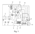
- Fig. 1 is a fluid system of a as a brewing unit 1 having coffee maker, here a coffee machine automatic beverage preparation device 2 shown.
- the beverage preparation device 2 comprises a water tank 3, from which water can be conveyed to a heating device 5 by means of a feed pump 4, the amount of water being detected by means of a flow meter 6.
- a pressure relief valve 7 is followed by which water is conveyed to brew coffee in the direction of a brewing unit 1 in which ground coffee is leached out by means of a coffee grinder, not shown, in particular integrated in the device 2.
- a drainage valve 10 controls the fluid flow.
- the pressure relief valve 7 ie by the pressure relief valve 7 promoted water can be used alternatively to bothmehlauslaugung or discharged in the direction of a drainage 8, which leads to a drip tray 9.
- the pressure relief valve 7 also serves to reduce an impermissible overpressure in the region of the heating device 5, in which this overpressure is discharged via the drainage valve 10 and the drainage 8 can. Leached ground coffee gets in the form of pomace cake 21 in a pulp container 22nd
- a fluid line 11 leads from the heater 5 to an automatically operable multi-way valve designed as a ceramic valve via which, depending on the operating mode, a hot water line 14 can be supplied with hot water, or a motive steam line 15 alternatively with steam or with water heated above 100 ° C. or a line 16 with air for frothing milk.
- the line 16 can, as will be explained later, depending on the operating mode so be an air line or an additional steam line through which steam or alternatively heated over 100 ° C water to generate water vapor can be promoted after the relaxation. Also, the line 16 can be used by a corresponding valve position of the multi-way valve 12 as a cleaning line for rinsing a milk line 17 with hot water or steam. In line 16, a throttle 18 is provided.
- heating device dividing means 19 are assigned. These include a branch or connecting line 20, with which the water vapor flowing through the fluid line 11 or the water heated above 100 ° C. for steam generation can be divided between the motive steam line 15 and the line 16 which then functions as an additional steam line.
- valve means 23 in the form of a manually or alternatively motor-operated valve 30, via which the connecting line 20 can be opened or closed to divide the water vapor or the very hot water or exclusively via the motive steam line 15 to supply a motive nozzle 24, which operates on the Venturi principle, and which generates a negative pressure, due to which milk is sucked via the milk line 17 from a milk container 25.
- the water vapor flowing out of the motive nozzle 24 is mixed with the milk, which is heated in this way and can thus flow down. In this way, the milk can be heated to about 40 ° C.
- valve means 23 are opened (second phase), so that the vapor flowing through the fluid conduit 11 or provided for generating steam is split between the fluid conduit 15 and the additional steam conduit 16, so that the milk steam at two different
- increased milk temperatures preferably 60 ° C and more can be achieved in a single heating device 5 for steam generation without increasing the same power of the same.
- valve means 23 may be part of this multi-way valve in an alternative embodiment of the multi-way valve 12, in which case can be dispensed with the valve 30.
- a section of milk heating means 26 is shown.
- the motive nozzle 24 in the steam or for the production of steam provided that is supplied according to heated hot water via the motive steam line 15.
- Water vapor exits at an outlet opening 27 of the propulsion nozzle operating according to the Venturi principle into a chamber 28 arranged downstream of the motive nozzle 24, which chamber is used in a frothing operating mode for frothing milk.
- the chamber 28 is followed by a discharge pipe 29 for heated milk.
- the chamber 28 opens a milk line 17 through which milk is sucked from a milk container, not shown, due to the Venturi effect when water vapor flows out of the outlet opening 27.
- the line 17 opens the line 16, through which in a AufMum cleansemodus air of the milk is supplied and is swirled in the chamber 28 with water vapor, so that the milk foams.
- water vapor then flows through the line 16, which serves as an additional steam line, into the milk line, in the direction of flow of the milk in front of the outlet opening 27 of the drive nozzle.
- steam may be introduced into the chamber 28 through a steam line (not shown) and / or into the outlet line 29, at least at least one position different from the outlet opening 27, in particular spaced therefrom.
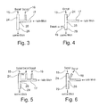
- Fig. 3 is the arrangement according to Fig. 2 shown in a very schematic way. Shown is a mode of operation hot milk production. Water vapor is supplied through the motive steam line 15 to the motive nozzle 24 and at the same time via the additional steam line 16 into the milk line 17 in the flow direction in front of the motive nozzle outlet. Cold milk is sucked in via the milk line 17 and thus heated at two different points and can flow out through the outlet line 29 in this strongly heated state.
- Fig. 5 shows an exemplary example that steam can also be supplied to more than two places.
- two additional steam lines 16 which open into the milk line 17, wherein at least one of the additional steam lines can be fed to the milk flow elsewhere.
- Fig. 6 shows an alternative embodiment in which water vapor is introduced via the additional steam line 16 into the chamber 28 and at the same time water vapor flows through the motive nozzle 24.
- Fig. 7 an operating state "milk standard temperature heating” is shown, in which water vapor is supplied exclusively via the motive nozzle 24 of the milk.
- the additional line 16 or this associated valve means 23 are closed.
- the illustrated fluid scheme may also be a representation of a first phase of hot milk production, namely a start-up phase in which water vapor is initially supplied exclusively via the drive nozzle 24 before valve means 23 release the additional steam line 16.
- Fig. 8 now corresponds to the second phase of the hot milk production mode.
- the representation corresponds Fig. 3 .
- Fig. 9 2 there is shown a foaming operation mode in which water vapor is supplied to the milk exclusively via the motive steam line 15 and the motive nozzle 24 into the chamber 28. Milk is sucked in via the milk line 17, as well as air via the line 16.
- Fig. 10 is one compared to Fig. 1 slightly modified fluid system of a coffee machine with brewing unit 1 shown. To avoid repetition, the following is only on the (essential) differences according to the embodiment according to Fig. 1 received. With regard to the similarities will be on Fig. 1 with associated figure description referenced.
- the fluid system comprises a water tank 3 from which water can be conveyed to a heating device 5 by means of a feed pump 4. From the heater 5 passes to over 100 ° C heated water and / or steam via a fluid line 11 to a multi-way valve 12, which in accordance with the fluid system in accordance with Fig. 1 tasks described.
- the fluid (hot water and / or steam) flowing in via the fluid line 11 can be divided into a motive steam line 15, which conveys the fluid to the motive nozzle, from which steam for generating a negative pressure can flow out and an additional steam line 16, which opens in the embodiment shown adjacent to the motive nozzle, so that via the additional line steam at a different from the outlet opening of the motive nozzle position of the milk can be supplied.
- the additional steam line does not correspond to an air line through which air can be supplied for milk frothing in a corresponding state of the milk.
- the line 31 which serves in the illustrated embodiment as an air and cleaning line in addition to the motive steam line heated to over 100 ° C water or steam so that then the water vapor is divided by the multi-way valve 12 by way of example on the lines 15 and 31.
Landscapes
- Engineering & Computer Science (AREA)
- Food Science & Technology (AREA)
- Apparatus For Making Beverages (AREA)
Abstract
Die Erfindung betrifft Getränkezubereitungsvorrichtung, insbesondere Kaf-feemaschine mit einer Brüheinheit (1) um Auslaugen von Kaffeemehl, mit Mitteln zum Erhitzen von Milch mit Wasserdampf, umfassend eine Heizeinrichtung (5) zum Erhitzen von Wasser zur Bildung von Wasserdampf, mit einer über eine Treibdampfleitung (15) mit dampfförmigen oder zur Dampferzeugung vorgesehenen Fluid versorgbare Treibdüse (24) zum Erzeugen von Unterdruck und dadurch Ansaugen von Milch durch eine Milchleitung (17), wobei Wasserdampf zum Erhitzen der Milch durch eine Auslassöffnung (27) der Treibdüse (24) in die angesaugte Milch einleitbar ist, wobei mindestens eine zusätzliche Dampfleitung (16) vorgesehen ist, durch die Wasserdampf an einer von der Auslassöffnung (27) der Treibdüse (24) unterschiedlichen Position der Milch zuführbar ist. Erfindungsgemäß ist vorgesehen, dass Wasserdampf durch die zusätzliche Dampfleitung (16) der Milch gleichzeitig mit der Einleitung von Wasserdampf durch die Auslassöffnung (27 der Treibdüse (24) zuführbar ist.The invention relates to beverage preparation apparatus, in particular coffee machine with a brewing unit (1) for leaching coffee grounds, with means for heating milk with steam, comprising a heating device (5) for heating water to form water vapor, with a via a motive steam line ( 15) provided with vaporous or for generating steam fluid provided motive nozzle (24) for generating negative pressure and thereby sucking milk through a milk line (17), wherein steam for heating the milk through an outlet opening (27) of the motive nozzle (24) sucked into the Milk is introduced, wherein at least one additional steam line (16) is provided, through which water vapor at one of the outlet opening (27) of the drive nozzle (24) different position of the milk can be fed. According to the invention, it is provided that water vapor can be supplied to the milk through the additional steam line (16) simultaneously with the introduction of water vapor through the outlet opening (27) of the motive nozzle (24).
Description
Die Erfindung betrifft eine Getränkezubereitungsvorrichtung gemäß dem Oberbegriff des Anspruchs 1, insbesondere in Form einer eine Brüheinheit umfassenden Kaffeemaschine, mit Mitteln zum Erhitzen von Milch mittels Wasserdampf, umfassend eine Heizeinrichtung zum Erhitzen von Wasser zur Bildung von Wasserdampf, mit einer über eine Treibdampfleitung mit dampfförmigem oder zur Dampferzeugung vorgesehenem Fluid versorgbare Treibdüse zum Erzeugen von Unterdruck und dadurch Ansaugen von Milch durch eine Milchleitung, wobei Wasserdampf zum Erhitzen der Milch durch eine Auslassöffnung der Treibdüse in die angesaugte Milch einleit-bar ist. Ferner betrifft die Erfindung ein Verfahren zum Betreiben einer Getränkezubereitungsvorrichtung gemäß dem Oberbegriff des Anspruchs 11.The invention relates to a beverage preparation device according to the preamble of claim 1, in particular in the form of a brewing unit comprising a coffee machine, with means for heating milk by means of steam, comprising a heater for heating water to form water vapor, with a via a motive steam line with vapor or For supplying steam generated fluid supplyable drive nozzle for generating negative pressure and thereby sucking milk through a milk line, wherein steam for heating the milk through an outlet opening of the motive nozzle in the sucked milk can be introduced bar. Furthermore, the invention relates to a method for operating a beverage preparation device according to the preamble of
Bei bekannten Kaffeevollautomaten für den Hausgebrauch sind, insbesondere bei hochpreisigeren Geräten, Mittel zum Erhitzen von Milch mittels Wasserdampf vorgesehen, wobei Wasserdampf durch eine sogenannte Treibdüse geleitet wird, um in der Art einer Strahlpumpe nach dem Venturiprinzip Milch durch eine Milchleitung anzusaugen. Dabei gelangt der Wasserdampf, der zur Erzeugung des Ansaug-, d.h. Unterdruckes genutzt wird in die Milch und erhitzt diese. In der Praxis reicht die über den Dampf zugeführte Energiemenge jedoch bei gegebener Flussgeschwindigkeit lediglich dazu aus, die Milch auf etwa 40°C zu erhitzen, welches von einigen Verbrauchern für bestimmte Kaffeeprodukte, wie beispielsweise Cappuccino oder Latte Macchiato als eine zu geringe Temperatur empfunden wird, da der Milchanteil bei derartigen Getränken vergleichsweise hoch und in der Folge die resultierende Mischtemperatur mit Kaffee bei nur 40°C warmer Milch zu gering ist.In known coffee machines for household use, means for heating milk by means of steam are provided, in particular in higher priced devices, wherein water vapor is passed through a so-called motive nozzle to suck in the manner of a jet pump according to the Venturi principle milk through a milk line. In this case, the water vapor, which is used to generate the intake, ie negative pressure, enters the milk and heats it. However, in practice, the amount of energy supplied through the steam at a given flow rate is merely sufficient to heat the milk to about 40 ° C, which is perceived by some consumers to be too low for certain coffee products, such as cappuccino or latte macchiato. since the milk content in such drinks is comparatively high and consequently the resulting mixing temperature with coffee at only 40 ° C warm milk is too low.
Aus der
Aus der
Zum weiteren Stand der Technik wird auf die
Ausgehend von dem zuvor beschriebenen Stand der Technik liegt der Erfindung die Aufgabe zugrunde, eine gattungsgemäße Getränkezubereitungsvorrichtung, insbesondere eine eine Brüheinheit zum Auslaugen von Kaffeemehl umfassende Kaffeemaschine so weiter zu bilden, dass mit dieser die Milchtemperatur auf ein höheres Temperaturniveau, insbesondere von über 50°C erhitzt werden kann, bevorzugt ohne eine größere oder eine zusätzliche Heizeinrichtung zum Erhitzen der Milch vorsehen zu müssen und bevorzugt ohne eine erhebliche Milchflussgeschwindigkeit hinnehmen zu müssen. Ferner besteht die Aufgabe darin, ein entsprechend verbessertes Verfahren zum Betreiben einer Getränkevorrichtung anzugeben, mit welcher höhere Milchtemperaturen als bisher erzeugt werden können.Based on the above-described prior art, the present invention seeks to further develop a generic beverage preparation device, in particular a coffee machine comprising a brewing unit for leaching coffee grounds that with this the milk temperature to a higher temperature level, in particular of about 50 ° C. can be heated, preferably without a larger one or to have to provide an additional heating device for heating the milk and preferably without having to accept a significant milk flow velocity. Furthermore, the object is to provide a correspondingly improved method for operating a beverage device with which higher milk temperatures than previously can be generated.
Diese Aufgabe wird hinsichtlich der Getränkezubereitungsvorrichtung mit den Merkmalen des Anspruchs 1 und hinsichtlich des Verfahrens mit den Merkmalen des Anspruchs 11 gelöst. Vorteilhafte Weiterbildungen der Erfindung sind in den Unteransprüchen angegeben. In den Rahmen der Erfindung fallen sämtliche Kombinationen aus zumindest zwei von in der Beschreibung, den Ansprüchen und/oder den Figuren offenbarten Merkmalen.This object is achieved with regard to the beverage preparation device having the features of claim 1 and with regard to the method having the features of
Zur Vermeidung von Wiederholungen sollen vorrichtungsgemäß offenbarte Merkmale als verfahrensgemäß offenbart gelten und beanspruchbar sein. Ebenso sollen verfahrensgemäß offenbarte Merkmale als vorrichtungsgemäß offenbart gelten und beanspruchbar sein.In order to avoid repetition, features disclosed according to the device should be regarded as disclosed according to the method and be able to be claimed. Likewise, according to the method disclosed features should be considered as device disclosed and claimed claimable.
Der Erfindung liegt der Gedanke zugrunde, die Milchtemperatur dadurch auf ein höheres Temperaturniveau zu bringen, dass Wasserdampf nicht nur durch die, insbesondere einzige, Auslassöffnung der Treibdüse hindurch in die Milch eingespeist wird, sondern gleichzeitig an mindestens einer weiteren Position in Strömungsrichtung der Milch vor oder nach dieser Auslassöffnung der Treibdüse.The invention is based on the idea to bring the milk temperature thereby to a higher temperature level, that water vapor is fed not only through the, in particular single, outlet opening of the motive nozzle into the milk, but at the same time at least one further position in the flow direction of the milk before or after this outlet opening of the motive nozzle.
Durch die Zuleitung von Wasserdampf in die Milch an mindestens zwei, insbesondere in Strömungsrichtung der Milch beabstandeten Positionen kann die Milchtemperatur überraschend deutlich erhöht werden, insbesondere auf Temperaturen von über 50°C, ganz besonders bevorzugt über 55°C, noch weiter bevorzugt über 60°C und ganz besonders bevorzugt auf eine Temperatur aus einem Temperaturbereich zwischen etwa 58°C und 75°C.By supplying water vapor into the milk at at least two positions, in particular in the direction of flow of the milk, the milk temperature can be increased surprisingly significantly, in particular to temperatures of more than 50 ° C., very particularly preferably above 55 ° C, even more preferably above 60 ° C, and most preferably to a temperature within a temperature range between about 58 ° C and 75 ° C.
Bei einer erfindungsgemäßen Getränkezubereitungsvorrichtung muss also zu diesem Zweck zusätzlich zu der die Auslassöffnung der Treibdüse mit Wasserdampf versorgenden Treibleitung mindestens eine zusätzliche Dampfleitung vorgesehen werden, über die Wasserdampf der Milch zugeführt werden kann. Im einfachsten Fall könnte dies dadurch realisiert werden, dass die Treibdüse zwei Auslassöffnungen für Dampf aufweist, wobei in diesem Fall die zusätzliche Dampfleitung von einem Abschnitt der Treibdüse gebildet wäre. Bevorzugt ist jedoch eine Ausführungsform, bei welcher die mindestens eines zusätzliche Dampfleitung benachbart, vorzugsweise mit Abstand zu der Treibdüse angeordnet ist und benachbart zu dieser, insbesondere beabstandet von dieser ausmündet, insbesondere in Strömungsrichtung vor oder nach der, insbesondere einzigen, Auslassöffnung der Treibdüse. Wie erwähnt, ist es grundsätzlich möglich mehr als eine zusätzliche Dampfleitung vorzusehen, um dann der Milch Wasserdampf an mehr als zwei unterschiedlichen Positionen zuzuführen, wobei die Zuführung von Wasserdampf in Strömungsrichtung der Milch vor und/oder nach der, insbesondere einzigen, Auslassöffnung der Treibdüse möglich ist. Bevorzugt weist die zusätzliche Dampfleitung eine Drossel (Verengungsstelle) auf, an welcher über die Siedetemperatur bei Atmosphärendruck erhitztes Fluid zu Wasserdampf entspannen kann.In the case of a beverage preparation device according to the invention, therefore, at least one additional steam line must be provided for this purpose, in addition to the fuel line supplying steam to the outlet opening of the motive nozzle, via which water vapor can be supplied to the milk. In the simplest case, this could be realized in that the motive nozzle has two outlet openings for steam, in which case the additional steam line would be formed by a section of the motive nozzle. However, an embodiment in which the at least one additional steam line is adjacent, preferably spaced from the drive nozzle and adjacent to this, in particular spaced from this opens, in particular in the flow direction before or after the, in particular single, outlet opening of the motive nozzle. As mentioned, it is in principle possible to provide more than one additional steam line in order to supply water to the milk at more than two different positions, the supply of water vapor in the direction of flow of the milk before and / or after the, in particular single, outlet opening of the motive nozzle possible is. The additional steam line preferably has a restrictor (constriction point) at which fluid heated above the boiling temperature at atmospheric pressure can relax to steam.
Im Rahmen der Anmeldung werden die Begriffe Treibdampfleitung und zusätzliche Dampfleitung so verstanden, dass über diese, insbesondere gleichzeitig, dampfförmiges oder zur Dampferzeugung vorgesehenes Fluid gefördert wird. Dies bedeutet, dass das Fluid bei einer möglichen Ausführungsform innerhalb der Treibdampfleitung aufgrund eines Überdrucks (noch) nicht dampfförmig sein muss, sondern lediglich eine Temperatur aufweisen muss, insbesondere von über 100°C, die gewährleistet, dass aus dem erhitzten Fluid nach einer entsprechenden Entspannung, insbesondere an einer Drossel, Wasserdampf entsteht. Bevorzugt wird zumindest abschnittsweise durch die Treibdampfleitung und/oder mindestens eine zusätzliche Leitung unmittelbar Wasserdampf transportiert.In the context of the application, the terms motive steam line and additional steam line are understood to be conveyed via these, in particular at the same time, vaporous or steam-generating fluid. This means that the fluid in a possible embodiment within the motive steam line due to an overpressure (not yet) must be non-vaporous, but only a temperature must have, in particular of over 100 ° C, which ensures that from the heated fluid after a corresponding relaxation, in particular at a throttle, water vapor is formed. Preferably, at least in sections, water vapor is transported directly through the motive steam line and / or at least one additional line.
Wie später noch erläutert werden wird, ist es besonders bevorzugt, wenn der Auslassöffnung der Treibdüse eine Kammer nachgeordnet ist, in welche die durch die Milchleitung angesaugte Milch mit dem durch die Auslassöffnung der Treibdüse ausströmenden Wasserdampf vermischt wird. Diese Kammer dient in Weiterbildung der Erfindung in einem von einem Milcherhitzungsbetriebszustand unterschiedlichen Aufschäumbetriebszustand zur Aufschäumung der Milch. Während dieses Aufschäumbetriebszustandes wird der Milch, insbesondere im Gegensatz zu dem reinen Milcherhitzungsbetriebszustand keine Luft über eine möglicherweise vorgesehene Luftzuleitung zugeführt. Die Kammer hat bevorzugt einen Innendurchmesser der einem mehrfachen Innendurchmesser der Milchleitung entspricht.As will be explained later, it is particularly preferred if the outlet opening of the motive nozzle is followed by a chamber into which the milk drawn in through the milk line is mixed with the water vapor flowing out through the outlet opening of the motive nozzle. This chamber is used in a further development of the invention in a different from a Milcherhitzungsbetriebszustand Aufschäumbetriebszustand for foaming the milk. During this Aufschäumbetriebszustandes the milk, in particular in contrast to the pure Milcherhitzungsbetriebszustand no air is supplied via a possibly provided air supply line. The chamber preferably has an inner diameter which corresponds to a multiple inner diameter of the milk line.
Besonders bevorzugt handelt es sich bei der erfindungsgemäßen Getränkezubereitungsvorrichtung um eine Getränkezubereitungsvorrichtung für den Hausgebrauch, die üblicherweise keine Mittel, insbesondere Proportionalventile oder Stößeleinrichtungen od.dgl. Verstellmechanismus zur stufenlosen oder gestuften Einstellung des Dampfvolumenstroms aufweistParticularly preferably, the beverage preparation device according to the invention is a beverage preparation device for domestic use, which usually no means, in particular proportional valves or ram devices or the like. Has adjustment mechanism for stepless or stepped adjustment of the steam flow rate
Ganz besonders bevorzugt ist eine Ausführungsvariante der Getränkezubereitungsvorrichtung, bei welcher der Heizeinrichtung Aufteilmittel, insbesondere umfassend eine Dampfleitungsverzweigung (z.B. eine, bevorzugt über ein manuell oder motorisch antreibbares Ventil öffnenbare oder verschließbare Verbindungsleitung bzw. Verzweigungsleitung zwischen der Treibdampfleitung oder einer vorgeordneten gemeinsamen Fluidleitung und der zusätzlichen Dampfleitung) vorgesehen sind, mit welchen das von der Heizeinrichtung bereitgestellte Fluid (Wasserdampf oder über den Siedepunkt bei Atmosphärendruck erhitztes Wasser) aufteilbar ist auf die Treibdampfleitung und die mindestens eine zusätzliche Dampfleitung. Mit anderen Worten ist weiterbildungsgemäß vorgesehen, Wasserdampf, der an mindestens zwei unterschiedlichen Positionen der Milch gleichzeitig zugeführt wird, mit einer einzigen Heizeinrichtung zu erzeugen, wodurch auf zusätzliche Heizeinrichtungen zur Erzeugung von Wasserdampf mit dem Ziel der Milcherhitzung verzichtet werden kann. Überraschenderweise kann durch die Aufteilung des Fluids die von der Heizeinrichtung zur Verfügung gestellte bzw. stellbare Wärmeenergiemenge besser ausgenutzt werden, als dies im Stand der Technik möglich ist. Auf diese Weise kann bei gleich groß wie bisher dimensionierten Heizeinrichtungen durch das Vorsehen der Möglichkeit der Einspeisung von Wasserdampf an einer weiteren bzw. zusätzlichen Position eine im Vergleich zur bisherigen Praxis deutlich erhöhte Milchtemperatur erzielt werden. Dabei wird überraschend die Geschwindigkeit, mit welcher die Milch gefördert wird im Vergleich zu einer Ausführung mit einer Wasserdampfzuleitung an der Treibdüse offensichtlich nur geringförmig bis gar nicht reduziert. Daher hat die weiterbildungsgemäße Lösung Vorteile gegen eine denkbarer Variante, bei welcher eine Temperaturerhöhung dadurch erzielt wird, dass künstlich die Milchgeschwindigkeit, mit der die Milch relativ zur Treibdüse strömt, herabgesetzt wird, um die Dampfmenge und damit den Energieeintrag pro Milchvolumeneinheit zu erhöhen.Especially preferred is a variant of the beverage preparation device, in which the heating device dividing means, in particular comprising a steam line branch (eg one, preferably via a manually or motor-driven valve openable or closable connection line or branch line between the motive steam line or an upstream common fluid line and the additional steam line) with which the fluid provided by the heater (water vapor or water heated above the boiling point at atmospheric pressure) can be divided into the motive steam line and the at least one additional steam line. In other words, according to the invention, provision is made for water vapor which is supplied simultaneously to at least two different positions of the milk to be produced with a single heating device, which makes it possible to dispense with additional heating devices for producing steam with the aim of milk heating. Surprisingly, the distribution of the fluid makes it possible to make better use of the amount of heat energy provided or adjustable by the heating device than is possible in the prior art. In this way, with the same size as previously dimensioned heaters by the provision of the possibility of feeding steam at a further or additional position, a significantly higher than in the past practice milk temperature can be achieved. Surprisingly, the speed with which the milk is conveyed is obviously only slightly reduced or not at all reduced in comparison to a design with a steam feed line at the drive nozzle. Therefore, the further development solution has advantages against a conceivable variant in which a temperature increase is achieved by artificially lowering the milk rate at which the milk flows relative to the motive nozzle, in order to increase the amount of steam and thus the energy input per milk volume unit.
Ganz besonders vorteilhaft hat es sich herausgestellt, mindestens eine zusätzliche Dampfleitung in die Milchleitung in Strömungsrichtung der Milch vor der Auslassöffnung der Treibdüse einmünden zu lassen. Konstruktiv besonders bevorzugt ist dabei eine Variante, bei welcher die zusätzliche Dampfleitung in einem (fakultativen) Aufschäumbetriebszustand der Getränkezubereitungsvorrichtung, in welchem in der (fakultativen) der Auslassöffnung der Treibdüse nachgeordneten Kammer Milch zu Milchschaum aufschäumbar ist, eine Luftleitung ist, durch die während des Aufschäumbetriebszustandes der Milch vor dem Eintreffen in die Kammer Luft zugeleitet wird. Besonders zweckmäßig ist es dabei, wenn diese Luftleitung eine Drossel beinhaltet.It has been found to be particularly advantageous to allow at least one additional steam line to open into the milk line in the direction of flow of the milk in front of the outlet opening of the motive nozzle. In a structurally particularly preferred embodiment, the additional steam line is in an (optional) foaming operating state of the beverage preparation device in which (optional) the Outlet opening of the motive nozzle downstream chamber milk is frothable to milk froth, an air line through which air is supplied during the Aufschäumbetriebszustandes the milk before it enters the chamber. It is particularly useful if this air line includes a throttle.
Von ganz besonderem Vorteil ist es, wenn die Dampfleitung neben der Luftleitungsfunktion in einem Aufschäumbetriebszustand noch die Funktion einer Reinigungsleitung erfüllt, durch die hindurch während eines Reinigungsbetriebszustandes Heißwasser und/oder Wasserdampf gefördert wird, um die Milchleitung von Anhaftungen zu befreien.It is of very particular advantage if the steam line in addition to the air line function in a Aufschäumbetriebszustand still fulfilling the function of a cleaning line through which during a cleaning operating state hot water and / or steam is promoted to rid the milk line of buildup.
Zusätzlich oder alternativ zu einer Einleitung von Wasserdampf in die Milchleitung ist es denkbar eine zusätzlich Dampfleitung in eine der Auslassöffnung der Treibdüse nachgeodnete (auch fakultative) Kammer einmünden zu lassen und auf diese Weise der Milch beabstandet zur Auslassöffnung der Treibdüse Wasserdampf zuzuführen.In addition or as an alternative to introducing steam into the milk line, it is conceivable to allow an additional steam line to open into a chamber (also optional) which is nachgeodnete in the outlet opening of the motive nozzle and in this way to supply water vapor to the outlet opening of the motive nozzle spaced from the milk.
Zusätzlich oder alternativ zu den zuvor beschriebenen Einleitpositionen für Wasserdampf ist es möglich eine zusätzliche Dampfleitung in eine Auslassleitung für erhitzte Milch einmünden zu lassen, durch die Milch einem Milchauslass der Getränkezubereitungsvorrichtung zuführbar ist, wobei die Auslassleitung bevorzugt einer der Auslassöffnung oder Treibdüse nachgeordneten (fakultativen) Kammer, insbesondere Aufschäumkammer nachgeordnet ist.In addition or as an alternative to the previously described steam vapor introduction positions, it is possible to open an additional steam line into a heated milk outlet line through which milk can be fed to a milk outlet of the beverage preparation device, the outlet line preferably being a chamber (optional) downstream of the outlet opening or drive nozzle , in particular foaming chamber is arranged downstream.
Besonders zweckmäßig ist eine Ausführungsform der Getränkezubereitungsvorrichtung, bei welcher der Heizeinrichtung ein, bevorzugt keramisches, insbesondere elektromotorisch, ansteuerbares Mehrwegeventil nachgeordnet ist, durch welches das von der Heizeinrichtung bereitgestellte Fluid zumindest einer Funktionseinheit, insbesondere zu den Milcherhitzungsmitteln, noch weiter bevorzugt zu der Treibdüse strömen kann. Dabei ist es weiter bevorzugt, wenn das Mehrwegeventil derart angeschlossen ist, dass mit diesem die Versorgung einer Funktionseinheit der Getränkezubereitungsvorrichtung in einem von einem Milcherhitzungsbetriebszustand unterschiedlichen Betriebszustand mit Luft, insbesondere zur Milchaufschäumung und/oder mit Reinigungswasser und/oder mit Reinigungswasserdampf (Reinigungsbetriebsmodus) steuerbar ist. Gemäß einer besonders bevorzugten Ausführungsform ist vorgenanntes Mehrwegeventil derart ausgebildet, dass mit diesem der von der Heizeinrichtung bereitgestellte Fluidstrom aufteilbar ist zum einen auf die zur Treibdüse führende Treibdampfleitung und zum anderen auf mindestens eine zusätzliche Dampfleitung, durch die Wasserdampf an der von der Auslassöffnung der Treibdüse unterschiedlichen Position der Milch zuführbar ist. Bei einer alternativen Ausführungsform kann, wie unten erläutert, zur Aufteilung dieses Fluids ein von dem Mehrwegeventil separates Ventil vorgesehen sein.Particularly expedient is an embodiment of the beverage preparation device in which the heating device is arranged downstream of a preferably ceramic, in particular electromotive, controllable multiway valve, by which the fluid provided by the heating device of at least one functional unit, in particular to the milk heating means, even more preferably can flow to the motive nozzle. It is further preferred if the multi-way valve is connected such that with this the supply of a functional unit of beverage preparation device in a different Milcherhitzungsbetriebszustand operating state with air, especially for milk frothing and / or cleaning water and / or cleaning water vapor (cleaning mode) is controllable , According to a particularly preferred embodiment, the above-mentioned multi-way valve is designed such that with this the provided by the heater fluid flow is divisible on the one leading to the motive nozzle motive steam line and on the other at least one additional steam line through the water vapor at the different from the outlet opening of the motive nozzle Position of the milk can be supplied. In an alternative embodiment, as explained below, a valve separate from the multi-way valve may be provided for dividing this fluid.
Besonders bevorzugt ist es, wenn Ventilmittel der Aufteilmittel, welche ggf. das zuvor erläuterte Mehrwegeventil und/oder mindestens ein zusätzliches (von einem Mehrwegeventil separates) oder alternatives Ventil umfassen können, derart manuell oder automatisch betätigbar sind, dass während des Milcherhitzungsvorgangs in einer ersten Phase Wasserdampf ausschließlich über die Treibdampfleitung und damit über die Auslassöffnung der Treibdüse der Milch zugeführt wird und in einer auf diese erste Phase nachfolgenden zweiten Phase zusätzlich Wasserdampf über die mindestens eine zusätzliche Dampfleitung der Milch zugeleitet wird. Bei einer alternativen Ausführungsvariante, bei welcher Mittel zur stufenlosen oder gestuften Einstellung eines Dampfvolumenstroms vorgesehen sind, insbesondere in Form mindestens eines Proportionalventils (auf die bzw. das bevorzugt verzichtet wird) ist es möglich in der ersten Phase Dampf über die Treibdampfleitung und gleichzeitig über die mindestens eine zusätzliche Dampfleitung der Milch zuzuleiten und in der zweiten auf die erste Phase folgenden Phase der Dampfvolumenstrom, der durch die zusätzliche Dampfleitung zugeführt wird im Vergleich zur ersten Phase erhöht wird.It is particularly preferred if valve means of the dividing means, which may optionally comprise the above-described multi-way valve and / or at least one additional (separate from a multi-way valve) or alternative valve, are manually or automatically operable such that during the milk heating process in a first phase Water vapor is fed exclusively via the motive steam line and thus via the outlet opening of the motive nozzle of the milk and in a second phase subsequent to this first phase additionally steam is fed via the at least one additional steam line of the milk. In an alternative embodiment, in which means are provided for continuous or stepped adjustment of a steam volume flow, in particular in the form of at least one proportional valve (which is preferably omitted), it is possible in the first phase steam over the motive steam line and at the same time over the at least to supply an additional steam line to the milk and in the second phase following the first phase the vapor volume flow supplied through the additional steam line is increased compared to the first phase.
Durch vorstehende Maßnahmen soll sichergestellt werden, dass die Treibdüse mit ausreichend Wasserdampf versorgt wird um einen ausreichenden Unterdruck erzeugen zu können, um hiermit ein störungsfreies Anlaufen des Ansaugvorgangs sicherzustellen. Nachdem dann die Milch strömt kann zusätzlich Dampf über die mindestens eine zusätzliche Dampfleitung dem Milchstrom zugeführt werden oder gemäß der alternativen Ausführungsform der Dampfvolumenstrom durch die zusätzliche Dampfleitung erhöht werden.The above measures are intended to ensure that the motive nozzle is supplied with sufficient water vapor in order to be able to generate a sufficient negative pressure in order to ensure trouble-free start-up of the intake process. After the milk then flows, steam can additionally be supplied to the milk stream via the at least one additional steam line or, according to the alternative embodiment, the steam volume flow through the additional steam line can be increased.
Wie eingangs erwähnt ist es besonders bevorzugt, insbesondere aus Kostengründen und zur Vereinfachung der Konstruktion auf Mittel zum stufenlosen Einstellen des Fluidvolumenstroms des von der Heizeinrichtung zur Verfügung gestellten dampfförmigen oder zur Dampferzeugung vorgesehenen Fluids zu verzichten. In diesem Fall ist es dann nur möglich eine Dampfleitung mit Hilfe von Ventilmitteln zu öffnen oder zu schließen, d.h. es gibt nur zwei Ventilzustände - offen, geschlossen.As mentioned above, it is particularly preferred, in particular for reasons of cost and to simplify the construction, to dispense with means for continuous adjustment of the fluid volume flow of the steam provided by the heating device or for the purpose of generating steam. In this case, it is then only possible to open or close a steam line by means of valve means, i. there are only two valve states - open, closed.
Die Erfindung führt auch auf ein Verfahren zum Betreiben einer Getränkezubereitungsvorrichtung, insbesondere zum Betreiben einer Kaffeemaschine, insbesondere eines Kaffeevollautomaten, wobei die Kaffeemaschine dann eine Brüheinheit zum Auslaugen von Kaffeemehl umfasst. Bevorzugt handelt es sich bei der nach dem erfindungsgemäßen Verfahren betriebenen Vorrichtung um eine nach dem Konzept der Erfindung ausgebildete Getränkezubereitungsvorrichtung. Erfindungsgemäß wird Wasserdampf an mindestens zwei unterschiedlichen Positionen der Milch zugeführt, wobei es besonders bevorzugt ist, wenn der gesamte, der in die Milch eingeleitete Wasserdampf von einer Heizeinrichtung stammt und lediglich entsprechend aufgeteilt wird. Wesentlich ist, dass eine Position, durch die Wasserdampf der Milch zugeführt wird, eine Auslassöffnung einer Treibdüse ist, mittels derer Milch durch eine Milchleitung nach dem Venturiprinzip angesaugt wird. Die mindestens eine weitere Position, an der der Milch Wasserdampf zugeführt wird, kann sich in Strömungsrichtung der Milch vor und/oder hinter der Auslassöffnung der Treibdüse befinden. Über die Milchleitung kann mittels der Treibdüse nach dem Venturiprinzip Milch aus einem externen Milchgefäß, beispielsweise einer Milchflasche oder eine Milchtüte angesaugt werden oder alternativ aus einem Milchbehälter, welcher fest in die Getränkezubereitungsvorrichtung integriert oder lösbar an dieser anordnenbar sein kann.The invention also leads to a method for operating a beverage preparation device, in particular for operating a coffee machine, in particular a coffee machine, the coffee machine then comprises a brewing unit for leaching coffee grounds. The device operated by the method according to the invention is preferably a beverage preparation device designed according to the concept of the invention. According to the invention, steam is supplied at at least two different positions of the milk, it being particularly preferred if the whole, which in the Milk introduced steam comes from a heater and is only divided accordingly. It is essential that a position through which water vapor is supplied to the milk, an outlet opening of a motive nozzle, by means of which milk is sucked through a milk pipe according to the Venturi principle. The at least one further position at which the milk is supplied with steam may be located in the flow direction of the milk in front of and / or behind the outlet opening of the motive nozzle. Milk can be sucked in from an external milk container, for example a milk bottle or a milk carton, or alternatively from a milk container, which can be permanently integrated into the beverage preparation device or can be detachably arranged thereon via the milk line.
Ganz besonders zweckmäßig ist es, wenn zur Gewährleistung eines störungsfreien Anlaufens des Milchflusses aus der Milchleitung während einer ersten Phase eines Milcherhitzungsvorgangs Dampf ausschließlich über die Auslassöffnung der Treibdüse der Milch zugeführt wird und in einer nachfolgenden zweiten Phase zusätzlich an der von der Auslassöffnung unterschiedlichen Position der Milch zugeführt wird. Alternativ ist es möglich während einer ersten Phase Dampf nicht nur durch die Auslassöffnung der Treibdüse der Milch zuzuführen, sondern gleichzeitig an mindestens einer unterschiedlichen Position, wobei dann bevorzugt während der zweiten Phase der Dampfvolumenstrom des Wasserdampfes, der an der von der Auslassöffnung unterschiedlichen Position der Milch zugeführt wird, im Vergleich zur ersten Phase erhöht wird. Dies kann beispielsweise dadurch realisiert werden, dass der freie Leitungsquerschnitt einer zusätzlichen Leitung in der zweiten Phase im Vergleich zu einer ersten Phase, beispielsweise mittels eines Proportionalventils vergrößert wird oder dadurch, dass in der zweiten Phase Wasserdampf durch mehr zusätzliche Dampfleitungen, d.h. an mehr zusätzlichen Positionen der Milch zugeführt wird als in der ersten Phase. Letzte Variante hat den Vorteil, dass die entsprechende Vorrichtung ohne Mittel zum stufenlosen Einstellen oder gestuften Einstellen des Dampfvolumenstroms durch eine Leitung auskommt. D.h., die Ausführungsform ist mit einer Getränkezubereitungsvorrichtung realisierbar, bei welcher die Leitungen bzw. Ventile nur zwischen zwei Zuständen, nämlich geöffnet oder geschlossen verstellt werden können.It is particularly expedient if steam is supplied exclusively via the outlet opening of the motive nozzle of the milk during a first phase of a milk heating process to ensure a trouble-free startup of the milk flow and in a subsequent second phase additionally at the position of the milk different from the outlet opening is supplied. Alternatively, it is possible to supply steam not only through the outlet opening of the motive nozzle of the milk during a first phase, but at the same time at at least one different position, then preferably during the second phase of the vapor flow of the water vapor at the different from the outlet opening of the milk is increased compared to the first phase is increased. This can be achieved, for example, by increasing the free line cross section of an additional line in the second phase compared to a first phase, for example by means of a proportional valve, or by virtue of the fact that in the second phase, water vapor is replaced by more additional steam lines, ie at more additional positions the milk is supplied as in the first phase. Last variant has the advantage that the corresponding Device without means for continuous adjustment or stepped adjustment of the steam flow rate through a pipe manages. That is, the embodiment can be realized with a beverage preparation device, in which the lines or valves can only be adjusted between two states, namely open or closed.
Besonders bevorzugt ist es, wenn die Getränkezubereitungsvorrichtung zwischen zwei unterschiedlichen Betriebsmodi verstellbar ist, nämlich einem Normaltemperaturmodus, währenddessen Wasserdampf der Milch ausschließlich über die Auslassöffnung der Treibdüse zugeführt wird und einem Hochtemperaturmodus, währenddessen die Milch erfindungsgemäß an mindestens einer von der Auslassöffnung der Treibdüse unterschiedlichen Position der Milch zugeleitet wird.It is particularly preferred if the beverage preparation device is adjustable between two different operating modes, namely a normal temperature mode, during which water vapor is supplied to the milk exclusively via the outlet opening of the motive nozzle and a high temperature mode, while the milk according to the invention at least one of the outlet opening of the motive nozzle different position Milk is fed.
Weitere Vorteile, Merkmale und Einzelheiten der Erfindung ergeben sich aus der nachfolgenden Beschreibung bevorzugter Ausführungsbeispiele sowie anhand der Zeichnungen.Further advantages, features and details of the invention will become apparent from the following description of preferred embodiments and from the drawings.
Diese zeigen in:
- Fig. 1:
- ein Fluidschema einer als Kaffeemaschine ausgebildeten Getränkezubereitungsvorrichtung,
- Fig. 2:
- eine Detaildarstellung einer möglichen Ausführungsform von Teilen von Milcherhitzungsmitteln,
- Fig. 3 bis Fig. 6:
- schematische Darstellung von unterschiedlichen Ausführungsvarianten der Wasserdampfzuführung,
- Fig. 7:
- einen Betriebsmodus Milcherhitzung "Normaltemperatur",
- Fig. 8:
- einen Betriebszustand Milcherhitzung erhöhte Temperatur,
- Fig. 9:
- einen möglichen Betriebszustand Milchaufschäumung, und
- Fig. 10:
- ein von
Fig. 1 unterschiedliches Fluidschema einer als Kaffeemaschine ausgebildeten Getränkezubereitungsvorrichtung.
- Fig. 1:
- a fluid scheme of a coffee maker designed as a coffee maker,
- Fig. 2:
- a detailed representation of a possible embodiment of parts of Milcherhitzungsmitteln,
- 3 to 6:
- schematic representation of different embodiments of the steam supply,
- Fig. 7:
- a mode of operation milk heating "normal temperature",
- Fig. 8:
- an operating condition milk heating elevated temperature,
- Fig. 9:
- a possible operating state milk frothing, and
- Fig. 10:
- one of
Fig. 1 different fluid scheme of a trained as a coffee maker beverage preparation device.
In den Figuren sind gleiche Elemente und Elemente mit der gleichen Funktion mit den gleichen Bezugszeichen gekennzeichnet.In the figures, like elements and elements having the same function are denoted by the same reference numerals.
In
Eine Fluidleitung 11 führt von der Heizeinrichtung 5 zu einem als Keramikventil ausgebildeten automatisiert betätigbaren Mehrwegeventil, über welches je nach Betriebsmodus eine Heißwasserleitung 14 mit heißem Wasser versorgt werden kann, oder eine Treibdampfleitung 15 alternativ mit Dampf oder mit über 100°C erhitztem Wasser oder eine Leitung 16 mit Luft zum Aufschäumen von Milch.A
Die Leitung 16 kann, wie später noch erläutert werden wird, je nach Betriebsmodus also eine Luftleitung sein oder eine zusätzliche Dampfleitung, durch welche Wasserdampf oder alternativ über 100°C erhitztes Wasser zur Generierung von Wasserdampf nach der Entspannung gefördert werden kann. Auch kann die Leitung 16 durch eine entsprechende Ventilstellung des Mehrwegeventils 12 als Reinigungsleitung zum Spülen einer Milchleitung 17 mit Heißwasser oder Dampf genutzt werden. In der Leitung 16 ist eine Drossel 18 vorgesehen.The
In dem konkreten Ausführungsbeispiel sind der Heizeinrichtung Aufteilmittel 19 zugeordnet. Diese umfassen eine Abzweig- bzw. Verbindungsleitung 20, mit der der durch die Fluidleitung 11 strömende Wasserdampf oder das über 100°C erhitzte Wasser zur Dampferzeugung aufgeteilt werden kann auf die Treibdampfleitung 15 und die dann als zusätzliche Dampfleitung fungierende Leitung 16.In the specific embodiment of the heating device dividing means 19 are assigned. These include a branch or connecting
In der Verbindungsleitung 20 befinden sich zusätzlich zu dem Mehrwegeventil 12 Ventilmittel 23 in Form eines manuell oder alternativ motorisch betätigbaren Ventils 30, über welches die Verbindungsleitung 20 geöffnet oder geschlossen werden kann, um den Wasserdampf bzw. das sehr heiße Wasser aufzuteilen oder ausschließlich über die Treibdampfleitung 15 einer Treibdüse 24 zuzuführen, die nach dem Venturiprinzip arbeitet, und die einen Unterdruck erzeugt, aufgrund dessen Milch über die Milchleitung 17 aus einem Milchbehälter 25 angesaugt wird. Der aus der Treibdüse 24 ausströmende Wasserdampf wird mit der Milch vermischt, die auf diese Weise erhitzt wird und so nach unten ausströmen kann. Auf diese Weise kann die Milch auf etwa 40°C erhitzt werden. Nach einem erfolgreichen Anlaufen des Milchstroms werden die Ventilmittel 23 geöffnet (zweite Phase), so dass das durch die Fluidleitung 11 strömende dampfförmige oder zur Dampferzeugung vorgesehene Fluid aufgeteilt wird auf die Fluidleitung 15 und die zusätzliche Dampfleitung 16, so dass der Milch Wasserdampf an zwei unterschiedlichen Stellen zugeführt wird, nämlich im Bereich des Auslasses der Treibdüse und vorgelagert an der Einmündung der Leitung 16 in die Milchleitung 17. Durch diese Maßnahme können bei einer einzigen Heizeinrichtung 5 zur Wasserdampferzeugung ohne Leistungserhöhung derselben erhöhte Milchtemperaturen von bevorzugt 60°C und mehr erreicht werden.In the connecting
Die Ventilmittel 23 können bei alternativer Ausgestaltung des Mehrwegeventils 12 aus Teil dieses Mehrwegeventils sein, wobei dann auf das Ventil 30 verzichtet werden kann.The valve means 23 may be part of this multi-way valve in an alternative embodiment of the
In
In die Kammer 28 mündet eine Milchleitung 17, durch welche aus einem nicht dargestellten Milchbehältnis aufgrund des Venturieffektes Milch angesaugt wird, wenn Wasserdampf aus der Auslassöffnung 27 ausströmt. In die Milchleitung 17 mündet die Leitung 16, durch welche in einem Aufschäumbetriebmodus Luft der Milch zugeführt wird und in der Kammer 28 mit Wasserdampf verwirbelt wird, so dass die Milch aufschäumt. Während eines Heißmilchbetriebsmodus strömt durch die dann als zusätzliche Dampfleitung dienende Leitung 16 Wasserdampf in die Milchleitung, und zwar in Fließrichtung der Milch vor der Auslassöffnung 27 der Treibdüse. Zusätzlich oder alternativ kann durch eine Dampfleitung (nicht gezeigt) Dampf in die Kammer 28 eingeleitet werden und/oder in die Auslassleitung 29, jedenfalls an mindestens einer von der Auslassöffnung 27 unterschiedlichen, insbesondere von dieser beabstandeten Position.In the
In
Bei dem Ausführungsbeispiel gemäß
In
In
In
Das Fluidsystem umfasst einen Wassertank 3 aus dem mittels einer Förderpumpe 4 Wasser zu einer Heizeinrichtung 5 gefördert werden kann. Von der Heizeinrichtung 5 gelangt auf über 100°C erhitztes Wasser und/oder Dampf über eine Fluidleitung 11 zu einem Mehrwegeventil 12, welches die im Zusammenhang mit dem Fluidsystem gemäß
Auch ist eine Aufteilung gleichzeitig auf alle drei Leitungen 15, 16, 31 bei entsprechender Ausgestaltung des Mehrwegeventils 12 realisierbar, so dass dann der Milch Dampf an zwei unterschiedlichen Stellen zugeführt wird. Bei dem Ausführungsbeispiel des Fludisystems gemäß
- 11
- Brüheinheitinfuser
- 22
- GetränkezubereitungsvorrichtungThe beverage maker
- 33
- Wassertankwater tank
- 44
- Förderpumpefeed pump
- 55
- Heizeinrichtungheater
- 66
- DurchflussmesserFlowmeter
- 77
- ÜberdruckventilPressure relief valve
- 88th
- Drainage (Leitung)Drainage (pipe)
- 99
- Tropfschaledrip tray
- 1010
- Drainageventildrainage valve
- 1111
- Fluidleitungfluid line
- 1212
- MehrwegeventilMulti-way valve
- 1414
- HeißwasserleitungHot water line
- 1515
- TreibdampfleitungBlowing steam line
- 1616
- Leitung (zusätzliche Dampfleitung), oder Luftleitung, oder Reinigungsleitung)Line (additional steam line), or air line, or cleaning line)
- 1717
- Milchleitungmilk line
- 1818
- Drosselthrottle
- 1919
- Aufteilmittelsplitting means
- 2020
- Verbindungsleitungconnecting line
- 2121
- Tresterkuchenpomace cake
- 2222
- Tresterbehälterpulp container
- 2323
- Ventilmittelvalve means
- 2424
- Treibdüsepropelling nozzle
- 2525
- Milchbehältermilk container
- 2626
- MilcherhitzungsmittelMilk heating means
- 2727
- Auslassöffnungoutlet
- 2828
- Kammerchamber
- 2929
- Auslassleitungoutlet pipe
- 3030
- VentilValve
- 3131
- Leitungmanagement
Claims (15)
dadurch gekennzeichnet,
dass der Milch Wasserdampf durch die zusätzliche Dampfleitung (16) gleichzeitig mit der Einleitung von Wasserdampf in die Milch durch die Auslassöffnung (27) der Treibdüse (24) zuführbar ist.Drinks preparation device, in particular coffee machine with a brewing unit (1) for leaching coffee grounds, with means for heating milk with water vapor, comprising a heating device (5) for heating water to form water vapor, with a steam or vapor traction line (15) for generating steam provided fluid supplyable drive nozzle (24) for generating negative pressure and thereby sucking milk through a milk line (17), wherein steam for heating the milk through an outlet opening (27) of the drive nozzle (24) is introduced into the sucked milk, wherein at least one additional steam line (16) is provided, through which water vapor can be fed to one of the outlet opening (27) of the drive nozzle (24) different position of the milk,
characterized,
in that the milk of water vapor can be fed through the additional steam line (16) simultaneously with the introduction of steam into the milk through the outlet opening (27) of the motive nozzle (24).
dadurch gekennzeichnet,
dass der Heizeinrichtung (5) Aufteilmittel (19), insbesondere Ventilmittel (23) und/oder eine Verzweigungsleitung, zugeordnet sind, mit denen das von der Heizeinrichtung (5) bereitgestellte Fluid aufteilbar ist auf die Treibdampfleitung (15) und die mindestens eine zusätzliche Dampfleitung (16).Drink preparation device according to claim 1,
characterized,
in that the heating device (5) has distribution means (19), in particular valve means (23) and / or a branch line, with which the fluid provided by the heating device (5) can be divided into the motive steam line (15) and the at least one additional steam line (16).
dadurch gekennzeichnet,
dass die zusätzliche Dampfleitung (16) in die Milchleitung (17) in Strömungsrichtung der Milch vor der der Auslassöffnung (27) der Treibdüse (24) mündet.Beverage preparation device according to one of claims 1 or 2,
characterized,
in that the additional steam line (16) opens into the milk line (17) in the flow direction of the milk in front of the outlet opening (27) of the motive nozzle (24).
dadurch gekennzeichnet,
dass die zusätzlich Dampfleitung (16) in einem Aufschäumbetriebszustand, in welchem in einer der Auslassöffnung (27) der Treibdüse (24) nachgeordneten Kammer (28) Milch zu Milchschaum aufschäumbar ist, eine, vorzugsweise eine Drossel (18) beinhaltende, Luftleitung (16) ist, durch die die der Kammer (28) zugeleitete Milch mit Luft versorgbar ist.Drink preparation device according to claim 3,
characterized,
in that the additional steam line (16) in a foaming operating state, in which milk to milk foam can be foamed in a chamber (28) arranged downstream of the outlet nozzle (27) of the motive nozzle (24), comprises an air line (16), preferably including a throttle (18). is, by which the chamber (28) supplied milk is supplied with air.
dadurch gekennzeichnet,
dass die zusätzliche Luftleitung (16) in einem Reinigungsbetriebszustand, in welchem die Milchleitung (17) reinigbar ist eine Reinigungsleitung (16) ist, durch die der Milchleitung (17) Heißwasser und/oder Heißdampf zuführbar ist.Drink preparation device according to one of claims 3 or 4,
characterized,
that the additional air line (16) in a cleaning mode, in which the milk line (17) is cleaned is a purge line (16) through which the milk line (17) Hot water and / or hot steam can be fed.
dadurch gekennzeichnet,
dass die zusätzliche Dampfleitung (16) in eine der Auslassöffnung (27) der Treibdüse (24) nachgeordnete Kammer (28) mündet.Beverage preparation device according to one of the preceding claims,
characterized,
in that the additional steam line (16) opens into a chamber (28) arranged downstream of the outlet opening (27) of the motive nozzle (24).
dadurch gekennzeichnet,
dass die zusätzliche Dampfleitung (16) in eine Auslassleitung (29) für erhitze Milch mündet, durch die Milch einem Milchauslass zuführbar ist, und dass die Auslassleitung (29) einer der Auslassöffnung (27) der Treibdüse (24) nachgeordneten Kammer (28) nachgeordnet ist.Beverage preparation device according to one of the preceding claims,
characterized,
in that the additional steam line (16) opens into a heated milk outlet line (29) through which milk can be fed to a milk outlet, and in that the outlet line (29) is arranged downstream of one of the outlet openings (27) of the downstream nozzle (24) is.
dadurch gekennzeichnet,
dass die Ventilmittel (23) ein, bevorzugt keramisches, insbesondere elektromotorisch ansteuerbares Mehrwegeventil (12) umfassen, mittels dessen neben der Dampfversorgung oder Wasserversorgung zur Dampferzeugung auch eine Heißwasserversorgung und/oder eine Luftversorgung und/oder eine Reinigungswasserversorgung und/oder eine Reinigungsdampfversorgung von Funktionseinheiten der Getränkezubereitungsvorrichtung (2) steuerbar ist.Beverage preparation device according to one of the preceding claims,
characterized,
in that the valve means (23) comprise a preferably ceramic, in particular electromotively activatable, multiway valve (12), by means of which, in addition to the steam supply or water supply for steam generation, also a hot water supply and / or an air supply and / or a cleaning water supply and / or a cleaning steam supply of functional units Beverage preparation device (2) is controllable.
dadurch gekennzeichnet,
dass die, bevorzugt einer Verzweigungsleitung und/oder der mindestens einen zusätzlichen Dampfleitung (16) zugeordneten Ventilmittel (23) derart manuell oder automatisch betätigbar sind, dass in einer ersten Phase eines Milcherhitzungsvorgangs Dampf ausschließlich über die er Treibdampfleitung (15) der Milch zugeführt und in einer nachfolgenden zweiten Phase zusätzlich über die mindestens eine zusätzliche Dampfleitung (16) oder dass während der ersten Phase Dampf über die Treibdampfleitung (15) und die mindestens eine zusätzliche Dampfleitung (16) der Milch zugeleitet wird, und dass in der zweiten Phase der Dampfvolumenstrom, der über die zusätzliche Dampfleitung (16) zugeführt wird im Vergleich zu ersten Phase erhöht wird und/oder dass in der zweiten Phase Wasserdampf über mehr zusätzliche Dampfleitungen (16) der Milch zugeführt wird als in der ersten Phase.Beverage preparation device according to one of the preceding claims,
characterized,
in that the valve means (23) assigned to a branching line and / or the at least one additional steam line (16) are manually or automatically operable such that in a first phase of a milk heating operation steam is supplied exclusively to the milk via the motive steam line (15) and into a subsequent second phase additionally via the at least one additional steam line (16) or that during the first phase steam via the motive steam line (15) and the at least one additional steam line (16) is fed to the milk, and that in the second phase the steam volume flow supplied via the additional steam line (16) is increased compared to the first phase and / or that in the second phase water vapor is added over more Steam lines (16) is supplied to the milk than in the first phase.
dadurch gekennzeichnet,
dass die, bevorzugt eine Verzweigungsleitung und/oder der mindestens einen zusätzlichen Dampfleitung zugeordneten Ventilmittel (23) ein von einem, bevorzugt keramischen, noch weiter bevorzugt elektromotorisch ansteuerbaren Mehrwegeventil 12 separates Ventil 30 ausgebildet sind.Drink preparation device (2) according to claim 9,
characterized,
in that the valve means (23), preferably associated with a branch line and / or the valve means (23) associated with at least one additional steam line, are formed by a separate valve 30, which is preferably ceramic, more preferably an electric motor-controlled multi-way valve 12.
dadurch gekennzeichnet,
dass der Milch gleichzeitig mit der Zuleitung von Wasserdampf durch die Auslassöffnung (27) der Treibdüse (24) in die Milch zusätzlich Wasserdampf an mindestens einer von der Auslassöffnung (27) der Treibdüse (24) unterschiedlichen Position zugeleitet wird.A method of operating a beverage preparation device (2), in particular according to one of the preceding claims, wherein water is heated to generate steam and water vapor through an outlet opening (27) of a motive nozzle (24) fed to the milk and thereby sucked milk from a milk line (17) and heated,
characterized,
that the milk additional steam into the milk at least one of the outlet opening (27) of the drive nozzle (24) of different position is supplied simultaneously with the supply of water vapor through the outlet opening (27) of the drive nozzle (24).
dadurch gekennzeichnet,
dass von einer Heizeinrichtung (5) bereitgestelltes, dampfförmiges oder zur Dampferzeugung vorgesehenes Fluid aufgeteilt wird und ein Teil über die Auslassöffnung (27) der Milch zugeleitet wird und ein anderer Teil an der von der Auslassöffnung (27) unterschiedlichen Position.Method according to claim 11,
characterized,
in that a vapor or vapor generating fluid provided by a heating device (5) is divided and a part is supplied to the milk via the outlet opening (27) and another part at the position different from the outlet opening (27).
dadurch gekennzeichnet,
dass während einer ersten Phase eines Milcherhitzungsvorgangs Dampf ausschließlich über die Auslassöffnung (27) der Treibdüse (24) der Milch zugeführt und in einer nachfolgenden zweiten Phase zusätzlich an der von der Auslassöffnung (27) unterschiedlichen Position, oder dass während der ersten Phase Dampf durch die Auslassöffnung (27) und an der von der Auslassöffnung (27) unterschiedlichen Position der Milch zugeleitet wird und dass in der zweiten Phase der Dampfvolumenstrom, der an der von der Auslassöffnung (27) unterschiedlichen Position der Milch zugeführt wird, im Vergleich zu ersten Phase erhöht wird und/oder dass in der zweiten Phase Wasserdampf über mehr zusätzliche Dampfleitungen (16) der Milch zugeführt wird als in der ersten Phase.Method according to one of claims 11 or 12,
characterized,
that supplied during a first phase of milk heating process steam exclusively via the outlet opening (27) of the drive nozzle (24) of the milk and also different in a subsequent second phase of the of the outlet opening (27) position, or that during the first phase of steam through the Outlet opening (27) and is supplied at the different from the outlet port (27) position of the milk and that in the second phase, the vapor flow rate, which is supplied at the different from the outlet port (27) position of the milk, compared to the first phase increases is and / or that in the second phase water vapor is supplied via more additional steam lines (16) of the milk than in the first phase.
dadurch gekennzeichnet,
dass in einem Normaltemperaturmodus Dampf der Milch ausschließlich über die Auslassöffnung (27) der Treibdüse (24) zugeführt wird und in einem Hochtemperaturmodus zusätzlich an der von der Auslassöffnung (27) unterschiedlichen Position.Method according to one of claims 11 to 13,
characterized,
that only via the outlet opening (27) of the drive nozzle (24) is supplied in a normal temperature mode steam milk and additionally different in a high temperature mode on the from the outlet port (27) position.
dadurch gekennzeichnet,
dass die Milch durch das gleichzeitige, zusätzliche Zuleiten von Dampf an der von der Auslassöffnung (27) der Treibdüse (24) unterschiedlichen Position, ohne Luftzufuhr über eine Luftleitung (16), auf eine Temperatur von über 55°C, insbesondere von über 60°C, insbesondere auf eine Temperatur aus einem Temperaturbereich zwischen 58°C und 75°C erhitzt wird.Method according to one of the preceding claims,
characterized,
in that the milk is heated to a temperature of more than 55 ° C, in particular more than 60 ° C, by the simultaneous, additional supply of steam at the position different from the outlet opening (27) of the motive nozzle (24), without air supply via an air line (16) C, in particular to a temperature from a temperature range between 58 ° C and 75 ° C is heated.
Applications Claiming Priority (1)
| Application Number | Priority Date | Filing Date | Title |
|---|---|---|---|
| DE102013104408.5A DE102013104408A1 (en) | 2013-04-30 | 2013-04-30 | Beverage preparation device with means for milk heating and operating method |
Publications (2)
| Publication Number | Publication Date |
|---|---|
| EP2798989A1 true EP2798989A1 (en) | 2014-11-05 |
| EP2798989B1 EP2798989B1 (en) | 2018-09-26 |
Family
ID=50624478
Family Applications (1)
| Application Number | Title | Priority Date | Filing Date |
|---|---|---|---|
| EP14166502.6A Active EP2798989B1 (en) | 2013-04-30 | 2014-04-30 | Beverage preparation device with means for milk heating and operating procedure |
Country Status (2)
| Country | Link |
|---|---|
| EP (1) | EP2798989B1 (en) |
| DE (1) | DE102013104408A1 (en) |
Cited By (8)
| Publication number | Priority date | Publication date | Assignee | Title |
|---|---|---|---|---|
| EP3023038A1 (en) * | 2014-11-19 | 2016-05-25 | Capitani S.r.l. | Machine for making milk-based drinks |
| EP3045092A1 (en) * | 2015-01-14 | 2016-07-20 | Eugster/Frismag AG | Beverage preparation device and method of operation |
| EP3045091A1 (en) * | 2015-01-14 | 2016-07-20 | Eugster/Frismag AG | Beverage preparation device and method of operation |
| CN106859345A (en) * | 2017-03-28 | 2017-06-20 | 宁波美侬咖啡机有限公司 | Pipe-line system and method that a kind of coffee machine milk road is cleaned automatically |
| WO2018052329A1 (en) * | 2016-09-13 | 2018-03-22 | Novadelta - Comércio E Indústria De Cafés, S.A. | Compact beverage dispensing device and beverage preparation machine with said beverage dispensing device |
| EP3332679A1 (en) * | 2016-12-07 | 2018-06-13 | Steiner AG Weggis | Device for heating milk or milk foam |
| CN113116140A (en) * | 2021-03-25 | 2021-07-16 | 广东纯米电器科技有限公司 | Water outlet control method, device, equipment and medium |
| US11582980B2 (en) | 2018-11-12 | 2023-02-21 | Steiner Ag Weggis | Method for heating milk or milk foam |
Families Citing this family (1)
| Publication number | Priority date | Publication date | Assignee | Title |
|---|---|---|---|---|
| DE102021206911A1 (en) | 2021-07-01 | 2023-01-05 | BSH Hausgeräte GmbH | Hot drink preparation device with controllable milk frother |
Citations (5)
| Publication number | Priority date | Publication date | Assignee | Title |
|---|---|---|---|---|
| EP1312292A1 (en) | 2001-11-14 | 2003-05-21 | Cafina AG | Device for creating milk-froth and for heating milk |
| DE60205290T2 (en) | 2001-02-23 | 2006-03-30 | Simatelex Manufactory Co. Ltd. | Device for dispensing milk froth or heated milk |
| EP1707090A1 (en) * | 2005-03-29 | 2006-10-04 | Cafina AG | Apparatus for the production of milk foam and/or for heating milk |
| DE102008058139A1 (en) * | 2008-11-20 | 2010-05-27 | Spengler Gmbh & Co. Kg | Arrangement for frothing milk and frothing unit for use in such an arrangement |
| DE102010007143A1 (en) | 2010-02-05 | 2011-08-11 | Eugster/Frismag Ag | Coffee machine with a foaming device and means for cleaning the foaming device and a milk suction line and method for rinsing the milk suction line |
-
2013
- 2013-04-30 DE DE102013104408.5A patent/DE102013104408A1/en not_active Withdrawn
-
2014
- 2014-04-30 EP EP14166502.6A patent/EP2798989B1/en active Active
Patent Citations (5)
| Publication number | Priority date | Publication date | Assignee | Title |
|---|---|---|---|---|
| DE60205290T2 (en) | 2001-02-23 | 2006-03-30 | Simatelex Manufactory Co. Ltd. | Device for dispensing milk froth or heated milk |
| EP1312292A1 (en) | 2001-11-14 | 2003-05-21 | Cafina AG | Device for creating milk-froth and for heating milk |
| EP1707090A1 (en) * | 2005-03-29 | 2006-10-04 | Cafina AG | Apparatus for the production of milk foam and/or for heating milk |
| DE102008058139A1 (en) * | 2008-11-20 | 2010-05-27 | Spengler Gmbh & Co. Kg | Arrangement for frothing milk and frothing unit for use in such an arrangement |
| DE102010007143A1 (en) | 2010-02-05 | 2011-08-11 | Eugster/Frismag Ag | Coffee machine with a foaming device and means for cleaning the foaming device and a milk suction line and method for rinsing the milk suction line |
Cited By (15)
| Publication number | Priority date | Publication date | Assignee | Title |
|---|---|---|---|---|
| EP3023038A1 (en) * | 2014-11-19 | 2016-05-25 | Capitani S.r.l. | Machine for making milk-based drinks |
| EP3045092A1 (en) * | 2015-01-14 | 2016-07-20 | Eugster/Frismag AG | Beverage preparation device and method of operation |
| EP3045091A1 (en) * | 2015-01-14 | 2016-07-20 | Eugster/Frismag AG | Beverage preparation device and method of operation |
| WO2018052329A1 (en) * | 2016-09-13 | 2018-03-22 | Novadelta - Comércio E Indústria De Cafés, S.A. | Compact beverage dispensing device and beverage preparation machine with said beverage dispensing device |
| CN109688881A (en) * | 2016-09-13 | 2019-04-26 | 诺威德尔塔咖啡贸易工业有限公司 | Compact beverage device for transferring and beverage preparation machine with the beverage device for transferring |
| US11178998B2 (en) | 2016-09-13 | 2021-11-23 | Novadelta—Comércio E Indústria De Cafés S.A. | Compact beverage discharge disposition and beverage preparation machine with said beverage discharge disposition |
| CN110312452B (en) * | 2016-12-07 | 2022-09-02 | 韦吉斯斯坦纳股份公司 | Device for heating milk or milk foam |
| EP3332679A1 (en) * | 2016-12-07 | 2018-06-13 | Steiner AG Weggis | Device for heating milk or milk foam |
| WO2018103972A1 (en) * | 2016-12-07 | 2018-06-14 | Steiner Ag Weggis | Device for heating milk or milk foam |
| CN110312452A (en) * | 2016-12-07 | 2019-10-08 | 韦吉斯斯坦纳股份公司 | For heating milk or the device of milk foam |
| US11666175B2 (en) | 2016-12-07 | 2023-06-06 | Steiner Ag Weggis | Device for heating milk or milk foam |
| CN106859345A (en) * | 2017-03-28 | 2017-06-20 | 宁波美侬咖啡机有限公司 | Pipe-line system and method that a kind of coffee machine milk road is cleaned automatically |
| US11582980B2 (en) | 2018-11-12 | 2023-02-21 | Steiner Ag Weggis | Method for heating milk or milk foam |
| CN113116140B (en) * | 2021-03-25 | 2023-04-07 | 广东纯米电器科技有限公司 | Water outlet control method, device, equipment and medium |
| CN113116140A (en) * | 2021-03-25 | 2021-07-16 | 广东纯米电器科技有限公司 | Water outlet control method, device, equipment and medium |
Also Published As
| Publication number | Publication date |
|---|---|
| EP2798989B1 (en) | 2018-09-26 |
| DE102013104408A1 (en) | 2014-12-31 |
Similar Documents
| Publication | Publication Date | Title |
|---|---|---|
| EP2798989B1 (en) | Beverage preparation device with means for milk heating and operating procedure | |
| EP2011421B1 (en) | Device for issuing milk-based drinks | |
| EP2294952B1 (en) | Device for dispensing milk and/or milk foam | |
| DE602005004558T2 (en) | Automatic device for heating and frothing milk | |
| EP2229851B1 (en) | Foaming device | |
| EP2220973B1 (en) | Output device for milk and/or milk foam and a coffee machine with such an output device | |
| EP2225976B1 (en) | Device for producing milk foam | |
| EP2329749B1 (en) | Coffee machine | |
| EP3079538B1 (en) | Milk frothing device, beverage preparation system and machine for preparing beverages | |
| DE102011102734A1 (en) | Device for frothing milk, beverage preparation with this device and method for frothing milk | |
| EP3079536B1 (en) | Milk foaming device, beverage preparation system and beverage preparation machine | |
| EP2987435A1 (en) | Device and method for foaming liquid food, in particular milk | |
| EP2534986A1 (en) | Device for heating and foaming a beverage | |
| EP2368467B1 (en) | Electric drink preparation machine | |
| DE102011084901A1 (en) | Device for dispensing milk and method for heating milk | |
| DE202009007945U1 (en) | Apparatus suitable for use in whipping milk | |
| EP2215942A1 (en) | Device for transporting milk | |
| EP2897507B1 (en) | Device for preparing hot or cold milk froth | |
| EP2263502A1 (en) | Device for heating and foaming milk | |
| EP3210505A1 (en) | Boiler unit for a device for heating and/or frothing of milk | |
| EP3042592B1 (en) | Method for producing milk froth and use of a hot beverage machine for producing a mixed coffee-milk beverage | |
| EP2988635B1 (en) | Method for preparing a mixed beverage, and automatic beverage machine for carrying out the method | |
| EP2143360B1 (en) | Coffee machine for producing and dispensing coffee drinks, in particular espresso coffee machine | |
| CH698188B1 (en) | Apparatus for heating and frothing liquids. | |
| EP3628193B1 (en) | Beverage preparation device with jet ejectors |
Legal Events
| Date | Code | Title | Description |
|---|---|---|---|
| PUAI | Public reference made under article 153(3) epc to a published international application that has entered the european phase |
Free format text: ORIGINAL CODE: 0009012 |
|
| 17P | Request for examination filed |
Effective date: 20140430 |
|
| AK | Designated contracting states |
Kind code of ref document: A1 Designated state(s): AL AT BE BG CH CY CZ DE DK EE ES FI FR GB GR HR HU IE IS IT LI LT LU LV MC MK MT NL NO PL PT RO RS SE SI SK SM TR |
|
| AX | Request for extension of the european patent |
Extension state: BA ME |
|
| R17P | Request for examination filed (corrected) |
Effective date: 20150504 |
|
| RBV | Designated contracting states (corrected) |
Designated state(s): AL AT BE BG CH CY CZ DE DK EE ES FI FR GB GR HR HU IE IS IT LI LT LU LV MC MK MT NL NO PL PT RO RS SE SI SK SM TR |
|
| GRAP | Despatch of communication of intention to grant a patent |
Free format text: ORIGINAL CODE: EPIDOSNIGR1 |
|
| STAA | Information on the status of an ep patent application or granted ep patent |
Free format text: STATUS: GRANT OF PATENT IS INTENDED |
|
| RIC1 | Information provided on ipc code assigned before grant |
Ipc: A47J 31/44 20060101AFI20180320BHEP |
|
| INTG | Intention to grant announced |
Effective date: 20180417 |
|
| GRAS | Grant fee paid |
Free format text: ORIGINAL CODE: EPIDOSNIGR3 |
|
| GRAA | (expected) grant |
Free format text: ORIGINAL CODE: 0009210 |
|
| STAA | Information on the status of an ep patent application or granted ep patent |
Free format text: STATUS: THE PATENT HAS BEEN GRANTED |
|
| AK | Designated contracting states |
Kind code of ref document: B1 Designated state(s): AL AT BE BG CH CY CZ DE DK EE ES FI FR GB GR HR HU IE IS IT LI LT LU LV MC MK MT NL NO PL PT RO RS SE SI SK SM TR |
|
| REG | Reference to a national code |
Ref country code: GB Ref legal event code: FG4D Free format text: NOT ENGLISH |
|
| REG | Reference to a national code |
Ref country code: CH Ref legal event code: EP |
|
| REG | Reference to a national code |
Ref country code: AT Ref legal event code: REF Ref document number: 1045014 Country of ref document: AT Kind code of ref document: T Effective date: 20181015 |
|
| REG | Reference to a national code |
Ref country code: IE Ref legal event code: FG4D Free format text: LANGUAGE OF EP DOCUMENT: GERMAN |
|
| REG | Reference to a national code |
Ref country code: DE Ref legal event code: R096 Ref document number: 502014009550 Country of ref document: DE |
|
| REG | Reference to a national code |
Ref country code: CH Ref legal event code: NV Representative=s name: BODENSEEPATENT PATENTANWAELTE BEHRMANN WAGNER , CH |
|
| REG | Reference to a national code |
Ref country code: NL Ref legal event code: FP |
|
| PG25 | Lapsed in a contracting state [announced via postgrant information from national office to epo] |
Ref country code: SE Free format text: LAPSE BECAUSE OF FAILURE TO SUBMIT A TRANSLATION OF THE DESCRIPTION OR TO PAY THE FEE WITHIN THE PRESCRIBED TIME-LIMIT Effective date: 20180926 Ref country code: RS Free format text: LAPSE BECAUSE OF FAILURE TO SUBMIT A TRANSLATION OF THE DESCRIPTION OR TO PAY THE FEE WITHIN THE PRESCRIBED TIME-LIMIT Effective date: 20180926 Ref country code: LT Free format text: LAPSE BECAUSE OF FAILURE TO SUBMIT A TRANSLATION OF THE DESCRIPTION OR TO PAY THE FEE WITHIN THE PRESCRIBED TIME-LIMIT Effective date: 20180926 Ref country code: BG Free format text: LAPSE BECAUSE OF FAILURE TO SUBMIT A TRANSLATION OF THE DESCRIPTION OR TO PAY THE FEE WITHIN THE PRESCRIBED TIME-LIMIT Effective date: 20181226 Ref country code: FI Free format text: LAPSE BECAUSE OF FAILURE TO SUBMIT A TRANSLATION OF THE DESCRIPTION OR TO PAY THE FEE WITHIN THE PRESCRIBED TIME-LIMIT Effective date: 20180926 Ref country code: GR Free format text: LAPSE BECAUSE OF FAILURE TO SUBMIT A TRANSLATION OF THE DESCRIPTION OR TO PAY THE FEE WITHIN THE PRESCRIBED TIME-LIMIT Effective date: 20181227 Ref country code: NO Free format text: LAPSE BECAUSE OF FAILURE TO SUBMIT A TRANSLATION OF THE DESCRIPTION OR TO PAY THE FEE WITHIN THE PRESCRIBED TIME-LIMIT Effective date: 20181226 |
|
| REG | Reference to a national code |
Ref country code: LT Ref legal event code: MG4D |
|
| PG25 | Lapsed in a contracting state [announced via postgrant information from national office to epo] |
Ref country code: LV Free format text: LAPSE BECAUSE OF FAILURE TO SUBMIT A TRANSLATION OF THE DESCRIPTION OR TO PAY THE FEE WITHIN THE PRESCRIBED TIME-LIMIT Effective date: 20180926 Ref country code: HR Free format text: LAPSE BECAUSE OF FAILURE TO SUBMIT A TRANSLATION OF THE DESCRIPTION OR TO PAY THE FEE WITHIN THE PRESCRIBED TIME-LIMIT Effective date: 20180926 Ref country code: AL Free format text: LAPSE BECAUSE OF FAILURE TO SUBMIT A TRANSLATION OF THE DESCRIPTION OR TO PAY THE FEE WITHIN THE PRESCRIBED TIME-LIMIT Effective date: 20180926 |
|
| PG25 | Lapsed in a contracting state [announced via postgrant information from national office to epo] |
Ref country code: RO Free format text: LAPSE BECAUSE OF FAILURE TO SUBMIT A TRANSLATION OF THE DESCRIPTION OR TO PAY THE FEE WITHIN THE PRESCRIBED TIME-LIMIT Effective date: 20180926 Ref country code: CZ Free format text: LAPSE BECAUSE OF FAILURE TO SUBMIT A TRANSLATION OF THE DESCRIPTION OR TO PAY THE FEE WITHIN THE PRESCRIBED TIME-LIMIT Effective date: 20180926 Ref country code: PL Free format text: LAPSE BECAUSE OF FAILURE TO SUBMIT A TRANSLATION OF THE DESCRIPTION OR TO PAY THE FEE WITHIN THE PRESCRIBED TIME-LIMIT Effective date: 20180926 Ref country code: IS Free format text: LAPSE BECAUSE OF FAILURE TO SUBMIT A TRANSLATION OF THE DESCRIPTION OR TO PAY THE FEE WITHIN THE PRESCRIBED TIME-LIMIT Effective date: 20190126 Ref country code: ES Free format text: LAPSE BECAUSE OF FAILURE TO SUBMIT A TRANSLATION OF THE DESCRIPTION OR TO PAY THE FEE WITHIN THE PRESCRIBED TIME-LIMIT Effective date: 20180926 Ref country code: EE Free format text: LAPSE BECAUSE OF FAILURE TO SUBMIT A TRANSLATION OF THE DESCRIPTION OR TO PAY THE FEE WITHIN THE PRESCRIBED TIME-LIMIT Effective date: 20180926 |
|
| PG25 | Lapsed in a contracting state [announced via postgrant information from national office to epo] |
Ref country code: SM Free format text: LAPSE BECAUSE OF FAILURE TO SUBMIT A TRANSLATION OF THE DESCRIPTION OR TO PAY THE FEE WITHIN THE PRESCRIBED TIME-LIMIT Effective date: 20180926 Ref country code: SK Free format text: LAPSE BECAUSE OF FAILURE TO SUBMIT A TRANSLATION OF THE DESCRIPTION OR TO PAY THE FEE WITHIN THE PRESCRIBED TIME-LIMIT Effective date: 20180926 Ref country code: PT Free format text: LAPSE BECAUSE OF FAILURE TO SUBMIT A TRANSLATION OF THE DESCRIPTION OR TO PAY THE FEE WITHIN THE PRESCRIBED TIME-LIMIT Effective date: 20190126 |
|
| REG | Reference to a national code |
Ref country code: DE Ref legal event code: R097 Ref document number: 502014009550 Country of ref document: DE |
|
| PG25 | Lapsed in a contracting state [announced via postgrant information from national office to epo] |
Ref country code: DK Free format text: LAPSE BECAUSE OF FAILURE TO SUBMIT A TRANSLATION OF THE DESCRIPTION OR TO PAY THE FEE WITHIN THE PRESCRIBED TIME-LIMIT Effective date: 20180926 |
|
| PLBE | No opposition filed within time limit |
Free format text: ORIGINAL CODE: 0009261 |
|
| STAA | Information on the status of an ep patent application or granted ep patent |
Free format text: STATUS: NO OPPOSITION FILED WITHIN TIME LIMIT |
|
| 26N | No opposition filed |
Effective date: 20190627 |
|
| PG25 | Lapsed in a contracting state [announced via postgrant information from national office to epo] |
Ref country code: SI Free format text: LAPSE BECAUSE OF FAILURE TO SUBMIT A TRANSLATION OF THE DESCRIPTION OR TO PAY THE FEE WITHIN THE PRESCRIBED TIME-LIMIT Effective date: 20180926 |
|
| REG | Reference to a national code |
Ref country code: BE Ref legal event code: MM Effective date: 20190430 |
|
| PG25 | Lapsed in a contracting state [announced via postgrant information from national office to epo] |
Ref country code: MC Free format text: LAPSE BECAUSE OF FAILURE TO SUBMIT A TRANSLATION OF THE DESCRIPTION OR TO PAY THE FEE WITHIN THE PRESCRIBED TIME-LIMIT Effective date: 20180926 Ref country code: LU Free format text: LAPSE BECAUSE OF NON-PAYMENT OF DUE FEES Effective date: 20190430 |
|
| PG25 | Lapsed in a contracting state [announced via postgrant information from national office to epo] |
Ref country code: BE Free format text: LAPSE BECAUSE OF NON-PAYMENT OF DUE FEES Effective date: 20190430 |
|
| PG25 | Lapsed in a contracting state [announced via postgrant information from national office to epo] |
Ref country code: TR Free format text: LAPSE BECAUSE OF FAILURE TO SUBMIT A TRANSLATION OF THE DESCRIPTION OR TO PAY THE FEE WITHIN THE PRESCRIBED TIME-LIMIT Effective date: 20180926 |
|
| PG25 | Lapsed in a contracting state [announced via postgrant information from national office to epo] |
Ref country code: IE Free format text: LAPSE BECAUSE OF NON-PAYMENT OF DUE FEES Effective date: 20190430 |
|
| REG | Reference to a national code |
Ref country code: AT Ref legal event code: MM01 Ref document number: 1045014 Country of ref document: AT Kind code of ref document: T Effective date: 20190430 |
|
| PG25 | Lapsed in a contracting state [announced via postgrant information from national office to epo] |
Ref country code: AT Free format text: LAPSE BECAUSE OF NON-PAYMENT OF DUE FEES Effective date: 20190430 |
|
| REG | Reference to a national code |
Ref country code: CH Ref legal event code: PFA Owner name: EUGSTER/FRISMAG AG, CH Free format text: FORMER OWNER: EUGSTER/FRISMAG AG, CH |
|
| PG25 | Lapsed in a contracting state [announced via postgrant information from national office to epo] |
Ref country code: CY Free format text: LAPSE BECAUSE OF FAILURE TO SUBMIT A TRANSLATION OF THE DESCRIPTION OR TO PAY THE FEE WITHIN THE PRESCRIBED TIME-LIMIT Effective date: 20180926 |
|
| PG25 | Lapsed in a contracting state [announced via postgrant information from national office to epo] |
Ref country code: MT Free format text: LAPSE BECAUSE OF FAILURE TO SUBMIT A TRANSLATION OF THE DESCRIPTION OR TO PAY THE FEE WITHIN THE PRESCRIBED TIME-LIMIT Effective date: 20180926 Ref country code: HU Free format text: LAPSE BECAUSE OF FAILURE TO SUBMIT A TRANSLATION OF THE DESCRIPTION OR TO PAY THE FEE WITHIN THE PRESCRIBED TIME-LIMIT; INVALID AB INITIO Effective date: 20140430 |
|
| PG25 | Lapsed in a contracting state [announced via postgrant information from national office to epo] |
Ref country code: MK Free format text: LAPSE BECAUSE OF FAILURE TO SUBMIT A TRANSLATION OF THE DESCRIPTION OR TO PAY THE FEE WITHIN THE PRESCRIBED TIME-LIMIT Effective date: 20180926 |
|
| PGFP | Annual fee paid to national office [announced via postgrant information from national office to epo] |
Ref country code: NL Payment date: 20240422 Year of fee payment: 11 |
|
| PGFP | Annual fee paid to national office [announced via postgrant information from national office to epo] |
Ref country code: GB Payment date: 20240423 Year of fee payment: 11 |
|
| PGFP | Annual fee paid to national office [announced via postgrant information from national office to epo] |
Ref country code: DE Payment date: 20240424 Year of fee payment: 11 |
|
| PGFP | Annual fee paid to national office [announced via postgrant information from national office to epo] |
Ref country code: CH Payment date: 20240501 Year of fee payment: 11 |
|
| PGFP | Annual fee paid to national office [announced via postgrant information from national office to epo] |
Ref country code: IT Payment date: 20240430 Year of fee payment: 11 Ref country code: FR Payment date: 20240417 Year of fee payment: 11 |