EP2797848B1 - Verfahren zur beschichtung von optischen wellenleitern - Google Patents
Verfahren zur beschichtung von optischen wellenleitern Download PDFInfo
- Publication number
- EP2797848B1 EP2797848B1 EP12818514.7A EP12818514A EP2797848B1 EP 2797848 B1 EP2797848 B1 EP 2797848B1 EP 12818514 A EP12818514 A EP 12818514A EP 2797848 B1 EP2797848 B1 EP 2797848B1
- Authority
- EP
- European Patent Office
- Prior art keywords
- waveguide
- coating
- target
- coating material
- laser
- Prior art date
- Legal status (The legal status is an assumption and is not a legal conclusion. Google has not performed a legal analysis and makes no representation as to the accuracy of the status listed.)
- Active
Links
Images
Classifications
-
- G—PHYSICS
- G02—OPTICS
- G02B—OPTICAL ELEMENTS, SYSTEMS OR APPARATUS
- G02B6/00—Light guides; Structural details of arrangements comprising light guides and other optical elements, e.g. couplings
- G02B6/24—Coupling light guides
- G02B6/26—Optical coupling means
- G02B6/27—Optical coupling means with polarisation selective and adjusting means
- G02B6/2726—Optical coupling means with polarisation selective and adjusting means in or on light guides, e.g. polarisation means assembled in a light guide
-
- B—PERFORMING OPERATIONS; TRANSPORTING
- B23—MACHINE TOOLS; METAL-WORKING NOT OTHERWISE PROVIDED FOR
- B23K—SOLDERING OR UNSOLDERING; WELDING; CLADDING OR PLATING BY SOLDERING OR WELDING; CUTTING BY APPLYING HEAT LOCALLY, e.g. FLAME CUTTING; WORKING BY LASER BEAM
- B23K26/00—Working by laser beam, e.g. welding, cutting or boring
- B23K26/02—Positioning or observing the workpiece, e.g. with respect to the point of impact; Aligning, aiming or focusing the laser beam
- B23K26/06—Shaping the laser beam, e.g. by masks or multi-focusing
- B23K26/062—Shaping the laser beam, e.g. by masks or multi-focusing by direct control of the laser beam
- B23K26/0622—Shaping the laser beam, e.g. by masks or multi-focusing by direct control of the laser beam by shaping pulses
-
- B—PERFORMING OPERATIONS; TRANSPORTING
- B23—MACHINE TOOLS; METAL-WORKING NOT OTHERWISE PROVIDED FOR
- B23K—SOLDERING OR UNSOLDERING; WELDING; CLADDING OR PLATING BY SOLDERING OR WELDING; CUTTING BY APPLYING HEAT LOCALLY, e.g. FLAME CUTTING; WORKING BY LASER BEAM
- B23K26/00—Working by laser beam, e.g. welding, cutting or boring
- B23K26/02—Positioning or observing the workpiece, e.g. with respect to the point of impact; Aligning, aiming or focusing the laser beam
- B23K26/06—Shaping the laser beam, e.g. by masks or multi-focusing
- B23K26/073—Shaping the laser spot
- B23K26/0734—Shaping the laser spot into an annular shape
-
- B—PERFORMING OPERATIONS; TRANSPORTING
- B23—MACHINE TOOLS; METAL-WORKING NOT OTHERWISE PROVIDED FOR
- B23K—SOLDERING OR UNSOLDERING; WELDING; CLADDING OR PLATING BY SOLDERING OR WELDING; CUTTING BY APPLYING HEAT LOCALLY, e.g. FLAME CUTTING; WORKING BY LASER BEAM
- B23K26/00—Working by laser beam, e.g. welding, cutting or boring
- B23K26/12—Working by laser beam, e.g. welding, cutting or boring in a special environment or atmosphere, e.g. in an enclosure
- B23K26/127—Working by laser beam, e.g. welding, cutting or boring in a special environment or atmosphere, e.g. in an enclosure in an enclosure
-
- B—PERFORMING OPERATIONS; TRANSPORTING
- B23—MACHINE TOOLS; METAL-WORKING NOT OTHERWISE PROVIDED FOR
- B23K—SOLDERING OR UNSOLDERING; WELDING; CLADDING OR PLATING BY SOLDERING OR WELDING; CUTTING BY APPLYING HEAT LOCALLY, e.g. FLAME CUTTING; WORKING BY LASER BEAM
- B23K26/00—Working by laser beam, e.g. welding, cutting or boring
- B23K26/20—Bonding
- B23K26/32—Bonding taking account of the properties of the material involved
-
- B—PERFORMING OPERATIONS; TRANSPORTING
- B23—MACHINE TOOLS; METAL-WORKING NOT OTHERWISE PROVIDED FOR
- B23K—SOLDERING OR UNSOLDERING; WELDING; CLADDING OR PLATING BY SOLDERING OR WELDING; CUTTING BY APPLYING HEAT LOCALLY, e.g. FLAME CUTTING; WORKING BY LASER BEAM
- B23K26/00—Working by laser beam, e.g. welding, cutting or boring
- B23K26/34—Laser welding for purposes other than joining
-
- C—CHEMISTRY; METALLURGY
- C03—GLASS; MINERAL OR SLAG WOOL
- C03C—CHEMICAL COMPOSITION OF GLASSES, GLAZES OR VITREOUS ENAMELS; SURFACE TREATMENT OF GLASS; SURFACE TREATMENT OF FIBRES OR FILAMENTS MADE FROM GLASS, MINERALS OR SLAGS; JOINING GLASS TO GLASS OR OTHER MATERIALS
- C03C25/00—Surface treatment of fibres or filaments made from glass, minerals or slags
- C03C25/10—Coating
- C03C25/104—Coating to obtain optical fibres
- C03C25/106—Single coatings
- C03C25/1061—Inorganic coatings
-
- C—CHEMISTRY; METALLURGY
- C03—GLASS; MINERAL OR SLAG WOOL
- C03C—CHEMICAL COMPOSITION OF GLASSES, GLAZES OR VITREOUS ENAMELS; SURFACE TREATMENT OF GLASS; SURFACE TREATMENT OF FIBRES OR FILAMENTS MADE FROM GLASS, MINERALS OR SLAGS; JOINING GLASS TO GLASS OR OTHER MATERIALS
- C03C25/00—Surface treatment of fibres or filaments made from glass, minerals or slags
- C03C25/10—Coating
- C03C25/12—General methods of coating; Devices therefor
- C03C25/22—Deposition from the vapour phase
-
- G—PHYSICS
- G02—OPTICS
- G02B—OPTICAL ELEMENTS, SYSTEMS OR APPARATUS
- G02B6/00—Light guides; Structural details of arrangements comprising light guides and other optical elements, e.g. couplings
- G02B6/02—Optical fibres with cladding with or without a coating
- G02B6/02395—Glass optical fibre with a protective coating, e.g. two layer polymer coating deposited directly on a silica cladding surface during fibre manufacture
-
- G—PHYSICS
- G02—OPTICS
- G02B—OPTICAL ELEMENTS, SYSTEMS OR APPARATUS
- G02B6/00—Light guides; Structural details of arrangements comprising light guides and other optical elements, e.g. couplings
- G02B6/02—Optical fibres with cladding with or without a coating
- G02B6/036—Optical fibres with cladding with or without a coating core or cladding comprising multiple layers
- G02B6/03694—Multiple layers differing in properties other than the refractive index, e.g. attenuation, diffusion, stress properties
-
- G—PHYSICS
- G02—OPTICS
- G02B—OPTICAL ELEMENTS, SYSTEMS OR APPARATUS
- G02B6/00—Light guides; Structural details of arrangements comprising light guides and other optical elements, e.g. couplings
- G02B6/10—Light guides; Structural details of arrangements comprising light guides and other optical elements, e.g. couplings of the optical waveguide type
- G02B6/12—Light guides; Structural details of arrangements comprising light guides and other optical elements, e.g. couplings of the optical waveguide type of the integrated circuit kind
-
- B—PERFORMING OPERATIONS; TRANSPORTING
- B23—MACHINE TOOLS; METAL-WORKING NOT OTHERWISE PROVIDED FOR
- B23K—SOLDERING OR UNSOLDERING; WELDING; CLADDING OR PLATING BY SOLDERING OR WELDING; CUTTING BY APPLYING HEAT LOCALLY, e.g. FLAME CUTTING; WORKING BY LASER BEAM
- B23K2103/00—Materials to be soldered, welded or cut
- B23K2103/50—Inorganic materials other than metals or composite materials
-
- Y—GENERAL TAGGING OF NEW TECHNOLOGICAL DEVELOPMENTS; GENERAL TAGGING OF CROSS-SECTIONAL TECHNOLOGIES SPANNING OVER SEVERAL SECTIONS OF THE IPC; TECHNICAL SUBJECTS COVERED BY FORMER USPC CROSS-REFERENCE ART COLLECTIONS [XRACs] AND DIGESTS
- Y10—TECHNICAL SUBJECTS COVERED BY FORMER USPC
- Y10T—TECHNICAL SUBJECTS COVERED BY FORMER US CLASSIFICATION
- Y10T156/00—Adhesive bonding and miscellaneous chemical manufacture
- Y10T156/10—Methods of surface bonding and/or assembly therefor
Definitions
- the invention relates to a method for producing an optical waveguide whose surface is at least partially coated with a coating material, wherein the coating material contained in a target is ablated by means of laser radiation of a process laser or transferred to another state of aggregation, after which the coating material on the surface of the Waveguide deposits and there forms a light guide modifying coating, which is reflected by the target or transmitted through the target laser radiation heats the waveguide, wherein the laser radiation is polarized and incident at a predetermined angle between 10 ° and 80 ° relative to the surface normal to the target.
- Optical waveguides such as optical fibers, are used for the generation and / or transport of high power electromagnetic radiation.
- part of the radiation is always guided in undesired regions (for example in the fiber cladding of an optical fiber), or a portion of the electromagnetic radiation guided at a certain angle into the optical waveguide is undesirable for subsequent optical components.
- the corresponding portion of the electromagnetic radiation even if its power makes up only a few percent of the total performed in the optical waveguide power, with correspondingly high total power to the destruction of the waveguide or adjacent components (for example, fiber connector) lead.
- the waveguide With comparatively low optical powers, it is possible to embed the waveguide in a highly transparent medium (e.g., adhesive) adapted to the refractive index.
- the refractive index must be greater than or equal to that of the waveguide so that light emerges from the waveguide.
- the light carried by the adhesive can then be absorbed in a suitable medium and converted to heat. The resulting heat is dissipated in a suitable form.
- One problem is the residual absorption occurring in the medium, which at high powers can lead to excessive heating up to destruction.
- Another way to dissipate unwanted electromagnetic radiation is to scan the surface of the waveguide, i.
- the outer surface of the fiber cladding of an optical fiber to roughen or chemically etch.
- the roughened or etched surface causes total reflection at the interface with the medium surrounding the optical waveguide to be avoided by local scattering.
- dilute hydrofluoric acid for chemical etching of the surface of a glass fiber is usually used dilute hydrofluoric acid.
- a disadvantage of this procedure is that the mechanical strength of the optical waveguide is weakened. The resulting fragility complicates the further use of the optical waveguide, such as for incorporation into a fiber connector. As a result, the production of corresponding optical arrangements is complicated and therefore expensive.
- Another problem is that dealing with dilute hydrofluoric acid is highly dangerous and harmful to the environment.
- the invention starting from a method of the type described above in that the waveguide is reflected by the target or transmitted through the target, the laser radiation being polarized and at a predetermined angle between 10 ° and 80 ° relative to the surface normal the target impinges and that in the method of the invention the process laser initially emit continuously at lower power to heat the waveguide, after which the process laser is pulsed at higher power to remove the coating material from the target which then settles on the heated surface of the waveguide jacket deposits.
- laser-based deposition of the coating material on the optical waveguide modifies its surface with respect to the light pipe to the adjacent medium in such a way that unwanted electromagnetic radiation is prevented from propagating in the optical waveguide.
- the deposited by laser deposition coating adheres firmly to the surface of the optical waveguide.
- the mechanical strength of the waveguide is not appreciably reduced by the light-scattering coating.
- the modified according to the invention optical waveguide can be used without the disadvantages described above, for example, for installation in fiber connectors or the construction of fiber lasers.
- a further advantage is that the production method according to the invention is compatible with splicing, cleaving and tapering processes, which can likewise be carried out on the same production line in a laser-based manner. This ensures a continuous and efficient assembly of optical waveguides.
- electromagnetic radiation creates an effective protection by the According to the invention applied light-scattering coating.
- This is advantageous for applications in which the electromagnetic radiation guided through the optical waveguide is used to process reflective materials (for example steel), for example for cutting or welding.
- reflected electromagnetic radiation is often coupled into the cladding of the optical waveguide and leads to the destruction of the optical waveguide itself and / or adjacent components.
- An advantage of the method according to the invention is also that the handling of hazardous hydrofluoric acid for etching the mantle surface of the optical waveguide can be omitted.
- the target is arranged in the manner (e.g., near, i.e., sufficiently far from, the waveguide) such that laser radiation reflected from the target or transmitted through the target heats the waveguide.
- the waveguide it is beneficial to heat the waveguide before the coating material is deposited thereon.
- polarized laser radiation is used, which impinges on the target at a predetermined angle between 10 degrees and 80 degrees relative to the surface normal. By the angle of incidence of the polarized radiation, the proportion of the radiation reflected on the optical waveguide and thus the heating of the optical waveguide can be controlled.
- the coating material for a light propagating in the optical waveguide at an application wavelength is largely transparent.
- the transparency of the coating applied according to the invention provides excellent high performance stability.
- the unwanted electromagnetic radiation dissipated by scattering from the optical waveguide is not absorbed in the coating and thus can not cause damage to the optical waveguide and the coating.
- the by the coating Scattered electromagnetic radiation can otherwise be converted into heat by suitable absorbers and thereby destroyed.
- the coating material should at least partially absorb the radiation of the process laser used to make the coating.
- the process laser heats the coating material contained in the target, thus converting it into the vapor phase, so that the coating material then deposits from the vapor phase on the mantle surface of the optical waveguide.
- a CO 2 laser As a process laser for the inventive method, for example, a CO 2 laser is suitable. Powerful CO 2 lasers are commercially available as extremely reliable standard components.
- doped or undoped silica glass is suitable as coating material.
- Silica glass is particularly heat-stable. This has the consequence that even with a warming due to low residual absorption of radiation no damage is to be feared.
- the silica glass is highly transparent at wavelengths that are relevant for many applications.
- silica glass absorbs the infrared radiation of a CO 2 laser, so that silica glass can be evaporated as a coating material by means of a CO 2 laser for the purpose of producing the light-scattering coating.
- the waveguide can be rotated about its longitudinal axis during the formation of the coating, so that the coating is deposited uniformly from all sides on the surface of the waveguide.
- the target encloses the waveguide (completely or partially) annularly.
- the target is irradiated by the process laser as far as possible in a ring zone which completely or partially encloses the waveguide.
- the light-scattering coating is deposited evenly from all sides on the surface of the waveguide.
- the waveguide can be moved continuously or intermittently relative to the target in the direction of its longitudinal axis.
- the coating may be formed on a surface portion of predetermined elongation (e.g., over several centimeters).
- a glass capillary can be collapsed onto the optical waveguide so as to produce a protective coating.
- a significant advantage of the invention is further that the formation of the coating can be carried out under normal atmosphere (i.e., e.g., air). A e.g. evacuable or fillable with process gas chamber is then not required for the inventive method. Thus, the coating can be produced according to the invention at a particularly low cost.
- the outer diameter of the optical waveguide according to the invention including coating can be 100 microns to 10 mm.
- the method according to the invention can be carried out repeatedly so that the coating material is deposited on the surface of the waveguide in several layers in succession.
- the waveguide can be performed several times along the target.
- the waveguide is excellently suited for packaging for a fiber connector.
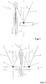
- the method according to the invention serves to produce an optical waveguide, for example an optical fiber 1, which consists of a fiber core 2 and a fiber cladding 3.
- an optical waveguide for example an optical fiber 1, which consists of a fiber core 2 and a fiber cladding 3.
- the outer surface of the fiber cladding 3 is partially coated with a coating material.
- the coating material is contained in a target 4, which in the in FIG. 1 illustrated embodiment is arranged laterally adjacent to the fiber 1 at a small distance.
- the target 4 surrounds the optical fiber 1 in an annular manner.
- the annular target 4 has according to FIG. 2 a central opening 5 through which the fiber 1 is passed.
- the laser radiation 6 is polarized and impinges on the target 4 at an adjustable angle ⁇ .
- angle ⁇ can be adjusted, how large the proportion of the reflected laser radiation 7, which impinges on the fiber cladding 3.
- the laser beam 6 is irradiated continuously (cw operation), whereby a certain temperature of the fiber cladding 3 is adjusted.
- the laser beam 6 is pulsed irradiated, for example, with a pulse duration in the range of about 100 microseconds to 100 ms, to remove the coating material from the target 4 (for example, by evaporation).
- the coating material then deposits on the heated fiber 1 and adheres to it stably.
- the coating material deposited from the target 4 on the fiber 1 can be pure or doped silica glass or else another transparent material which has a sufficiently good absorption in the range of the wavelength of the laser radiation 6.
- the fiber 1 is rotated about its longitudinal axis. At the same time, the fiber 1 is advanced continuously or intermittently in the direction of the arrow along its longitudinal axis.
- the laser beam 6 can be deflected either continuously, or it is an annular or ring segment-shaped laser beam 6 formed by suitable optics.
- the coating material deposits from all sides over the entire circumference of the fiber 1 on the jacket 3 from.
- the material deposited on the fiber 1 of the coating material is highly transparent at a given application wavelength, as the fiber material itself. Therefore, no significant absorption of the radiation propagating in the waveguide takes place in the coating applied according to the invention.
- the Coating is used only for light scattering in order to eliminate that portion of the radiation propagating in the fiber cladding 3, which is undesirable for the relevant application.
Landscapes
- Physics & Mathematics (AREA)
- Optics & Photonics (AREA)
- Engineering & Computer Science (AREA)
- Plasma & Fusion (AREA)
- Chemical & Material Sciences (AREA)
- Mechanical Engineering (AREA)
- Life Sciences & Earth Sciences (AREA)
- General Physics & Mathematics (AREA)
- Geochemistry & Mineralogy (AREA)
- Materials Engineering (AREA)
- Organic Chemistry (AREA)
- General Life Sciences & Earth Sciences (AREA)
- General Chemical & Material Sciences (AREA)
- Chemical Kinetics & Catalysis (AREA)
- Inorganic Chemistry (AREA)
- Microelectronics & Electronic Packaging (AREA)
- Optical Integrated Circuits (AREA)
Description
- Die Erfindung betrifft Verfahren zur Herstellung eines optischen Wellenleiters, dessen Oberfläche zumindest teilweise mit einem Beschichtungsstoff überzogen ist, wobei der in einem Target enthaltene Beschichtungsstoff mit Hilfe von Laserstrahlung eines Prozesslasers abgetragen oder in einen anderen Aggregatszustand überführt wird, wonach sich der Beschichtungsstoff auf der Oberfläche des Wellenleiters ablagert und dort einen die Lichtführung modifizierenden Überzug bildet, wobei von dem Target reflektierte oder durch das Target transmittierte Laserstrahlung den Wellenleiter erwärmt, wobei die Laserstrahlung polarisiert ist und unter einem vorgegebenen Winkel zwischen 10° und 80° relativ zur Oberflächennormalen auf das Target auftrifft.
- Optische Wellenleiter, wie zum Beispiel optische Fasern, werden für die Erzeugung und/oder den Transport elektromagnetischer Strahlung hoher Leistung verwendet. Dabei wird stets ein Teil der Strahlung auch in unerwünschten Bereichen (zum Beispiel im Fasermantel einer optischen Faser) geführt, oder ein unter einem bestimmten Winkel in den optischen Wellenleiter geführter Teil der elektromagnetischen Strahlung ist für nachfolgende optische Komponenten unerwünscht. Der entsprechende Anteil der elektromagnetischen Strahlung kann, auch wenn dessen Leistung nur wenige Prozent der insgesamt in dem optischen Wellenleiter geführten Leistung ausmacht, bei entsprechend hoher Gesamtleistung zur Zerstörung des Wellenleiters oder angrenzender Bauteile (zum Beispiel Faserstecker) führen.
- Bei vergleichsweise geringen optischen Leistungen besteht die Möglichkeit, den Wellenleiter in ein hochtransparentes Medium (z.B. Klebstoff) einzubetten, der hinsichtlich des Brechungsindex angepasst ist. Der Brechungsindex muss dabei größer oder gleich demjenigen des Wellenleiters sein, so dass Licht aus dem Wellenleiter austritt. Das durch den Klebstoff transportierte Licht kann dann in einem geeigneten Medium absorbiert und in Wärme umgewandelt werden. Die entstehende Wärme wird in geeigneter Form abgeführt. Ein Problem ist die in dem Medium auftretende Restabsorption, die bei hohen Leistungen zu starker Erwärmung bis zur Zerstörung führen kann.
- Eine weitere Möglichkeit, unerwünschte elektromagnetische Strahlung abzuführen besteht darin, die Oberfläche des Wellenleiters, d.h. zum Beispiel die äußere Oberfläche des Fasermantels einer optischen Faser, anzurauen oder chemisch anzuätzen. Die angeraute oder angeätzte Oberfläche bewirkt, dass Totalreflektion an der Grenzfläche zu dem den optischen Wellenleiter umgebenden Medium durch lokale Streuung vermieden wird. Zum chemischen Anätzen der Oberfläche einer Glasfaser verwendet man üblicherweise verdünnte Flusssäure. Nachteilig ist bei diesem Vorgehen, dass die mechanische Festigkeit des optischen Wellenleiters geschwächt wird. Die resultierende Fragilität erschwert die weitere Verwendung des optischen Wellenleiters, wie zum Beispiel zum Einbau in einen Faserstecker. Dadurch wird die Herstellung entsprechender optischer Anordnungen aufwendig und damit teuer. Problematisch ist weiterhin, dass der Umgang mit verdünnter Flusssäure hochgefährlich und umweltschädlich ist.
- Andere aus dem Stand der Technik bekannte Verfahren, bei denen direkt (teil-) absorbierende Materialien auf der Oberfläche des optischen Wellenleiters angebracht werden, sind wegen des hohen Wärmeeintrags für hohe Leistungen der zu erzeugenden oder zu führenden elektromagnetischen Strahlung nicht geeignet. Ein Verfahren nach dem Oberbegriff des Anspruchs 1 ist aus der Veröffentlichung "Pulsed laser deposited ZnO film on side-polished fiber as a gas sensing element"; Anna Og. Dikosvska et al., APPLIED OPTICS, OPTICAL SOCIETY OF AMERICA, WASHINGTON, DC; US, Bd. 46, Nr. 13, 1. Mai 2007 (2007-05-01), Seiten 2481-2485; bekannt.
- Somit ist es Aufgabe der Erfindung, ein gegenüber dem Stand der Technik verbessertes Verfahren zur Herstellung von optischen Wellenleitern bereitzustellen, bei denen die Führung unerwünschter elektromagnetischer Strahlung bzw. die Führung von Strahlung in unerwünschten Bereichen des Wellenleiters vermieden wird. Aufgabe ist es somit, anders ausgedrückt, optische Wellenleiter bereitzustellen, die hochleistungsstabil sind und eine verbesserte Strahlqualität liefern.
- Diese Aufgabe löst die Erfindung ausgehend von einem Verfahren der eingangs angegeben Art dadurch, dass von dem Target reflektierte oder durch das Target transmittierte Laserstrahlung den Wellenleiter erwärmt, wobei die Laserstrahlung polarisiert ist und unter einem vorgegebenen Winkel zwischen 10° und 80° relativ zur Oberflächennormalen auf das Target auftrifft und daß der Prozesslaser bei dem erfindungsgemäßen Verfahren zunächst kontinuierlich bei niedrigerer Leistung emittiert, um den Wellenleiter zu erwärmen, wonach der Prozesslaser dann gepulst bei höherer Leistung betrieben wird, um den Beschichtungsstoff von dem Target abzutragen, der sich dann auf der erwärmten Oberfläche des Wellenleitermantels ablagert.
- Gemäß der Erfindung wird durch laserbasierte Deposition des Beschichtungsstoffs auf dem optischen Wellenleiter dessen Oberfläche hinsichtlich der Lichtleitung zum angrenzenden Medium in der Weise modifiziert, dass unerwünschte elektromagnetische Strahlung an der Propagation in dem optischen Wellenleiter gehindert wird. Die durch Laserdeposition abgelagerte Beschichtung haftet fest auf der Oberfläche des optischen Wellenleiters. Die mechanische Festigkeit des Wellenleiters wird durch den lichtstreuenden Überzug nicht nennenswert gemindert. Der gemäß der Erfindung modifizierte optische Wellenleiter kann ohne die oben beschriebenen Nachteile verwendet werden, zum Beispiel für den Einbau in Faserstecker oder den Aufbau von Faserlasern.
- Ein weiterer Vorteil ist, dass das erfindungsgemäße Herstellungsverfahren kompatibel zu Spleiß-, Cleave- und Taperprozessen ist, die ebenfalls laserbasiert auf der gleichen Herstellungsanlage durchgeführt werden können. Dies gewährleistet eine kontinuierliche und effiziente Konfektionierung von optischen Wellenleitern.
- Schließlich wird durch die erfindungsgemäß herbeigeführte Entfernung unerwünschter elektromagnetischer Strahlung eine Verbesserung der Strahlqualität der aus dem optischen Wellenleiter austretenden Strahlung erreicht. Dadurch ergeben sich weitere Anwendungsfelder.
- Auch für gegebenenfalls in den optischen Wellenleiter zurücklaufende elektromagnetische Strahlung entsteht ein wirksamer Schutz durch den erfindungsgemäß aufgebrachten lichtstreuenden Überzug. Dies ist vorteilhaft für Anwendungen, bei denen die durch den optischen Wellenleiter geführte elektromagnetische Strahlung zur Bearbeitung reflektierender Werkstoffe (zum Beispiel Stahl), beispielsweise zum Schneiden oder Schweißen, verwendet wird. Bei derartigen Anwendungen wird reflektierte elektromagnetische Strahlung häufig in den Mantel des optischen Wellenleiters eingekoppelt und führt zur Zerstörung des optischen Wellenleiters selbst und/oder angrenzender Bauteile. Diese Probleme können durch den erfindungsgemäß hergestellten optischen Wellenleiter vermieden werden.
- Ein Vorteil des erfindungsgemäßen Verfahrens ist außerdem, dass der Umgang mit gefährlicher Flusssäure zum Anätzen der Manteloberfläche des optischen Wellenleiters unterbleiben kann.
- Gemäß der Erfindung ist das Target in der Weise (z.B. in der Nähe, d.h. in hinreichend geringem Abstand zum Wellenleiter) angeordnet, so dass von dem Target reflektierte oder durch das Target transmittierte Laserstrahlung den Wellenleiter erwärmt. Es zeigt sich, dass es zur Herstellung eines qualitativ guten und gut anhaftenden lichtstreuenden Überzugs von Vorteil ist, den Wellenleiter zu erwärmen, bevor der Beschichtungsstoff darauf abgelagert wird. Dabei wird zum Abtragen des Beschichtungsstoffes polarisierte Laserstrahlung verwendet, die unter einem vorgegebenen Winkel zwischen 10 Grad und 80 Grad relativ zur Oberflächennormalen auf das Target auftrifft. Durch den Auftreffwinkel der polarisierten Strahlung kann der Anteil der auf den optischen Wellenleiter reflektierten Strahlung und damit die Erwärmung des optischen Wellenleiters kontrolliert werden.
- Bei einer bevorzugten Ausgestaltung des erfindungsgemäßen Verfahrens ist der Beschichtungsstoff für ein in dem optischen Wellenleiter bei einer Applikationswellenlänge propagierendes Licht weitgehend transparent. Die Transparenz des gemäß der Erfindung aufgebrachten Überzugs sorgt für eine ausgezeichnete Hochleistungsstabilität. Die aus dem optischen Wellenleiter durch Streuung abgeführte unerwünschte elektromagnetische Strahlung wird in dem Überzug nicht absorbiert und kann somit nicht zu Beschädigungen des optischen Wellenleiters und des Überzugs führen. Die durch den Überzug gestreute elektromagnetische Strahlung kann anderweitig durch geeignete Absorber in Wärme umgewandelt und dadurch vernichtet werden.
- Andererseits sollte der Beschichtungsstoff die Strahlung des für die Herstellung des Überzugs verwendeten Prozesslasers zumindest teilweise absorbieren. Auf diese Weise erhitzt der Prozesslaser den in dem Target enthaltenden Beschichtungsstoff, überführt ihn so in die Dampfphase, so dass sich der Beschichtungsstoff dann aus der Dampfphase auf der Manteloberfläche des optischen Wellenleiters ablagert.
- Als Prozesslaser für das erfindungsgemäße Verfahren eignet sich zum Beispiel ein CO2-Laser. Leistungsstarke CO2-Laser sind als äußerst zuverlässige Standardkomponenten kommerziell erhältlich.
- Als Beschichtungsstoff eignet sich bei einer bevorzugten Ausgestaltung des erfindungsgemäßen Verfahrens dotiertes oder undotiertes Kieselglas, oder ein anderes zum Material des Wellenleiters chemisch äquivalentes Material. Kieselglas ist besonders wärmestabil. Das hat zur Folge, dass selbst bei einer Erwärmung auf Grund geringer Restabsorption von Strahlung keine Beschädigung zu befürchten ist. Das Kieselglas ist bei für viele Applikationen relevanten Wellenlängen hochtransparent. Andererseits absorbiert Kieselglas die Infrarotstrahlung eines CO2-Lasers, so dass Kieselglas als Beschichtungsstoff mittels eines CO2-Lasers zum Zwecke der Erzeugung des lichtstreuenden Überzugs verdampft werden kann.
- Bei dem erfindungsgemäßen Verfahren kann der Wellenleiter während der Bildung des Überzugs um seine Längsachse gedreht werden, so dass die Beschichtung gleichmäßig von allen Seiten auf der Oberfläche des Wellenleiters abgeschieden wird.
- Besonders bevorzugt ist eine Ausgestaltung des erfindungsgemäßen Verfahrens, bei der das Target den Wellenleiter (ganz oder teilweise) ringförmig umschließt. Dabei wird das Target von dem Prozesslaser möglichst in einer den Wellenleiter ganz oder teilweise umschließenden Ringzone bestrahlt. Bei diesem Vorgehen wird der lichtstreuende Überzug gleichmäßig von allen Seiten auf der Oberfläche des Wellenleiters abgelagert.
- Während der erfindungsgemäßen Ablagerung des Beschichtungsstoffes auf der Oberfläche des Wellenleiters kann der Wellenleiter in Richtung seiner Längsachse kontinuierlich oder intermittierend relativ zu dem Target bewegt werden. Auf diese Weise kann der Überzug auf einem Oberflächenabschnitt mit vorgebbarer Längsausdehnung (z.B. über mehrere Zentimeter) gebildet werden.
- Bei dem erfindungsgemäßen Verfahren kann nach der Bildung des Überzugs eine Glaskapillare auf den optischen Wellenleiter aufkollabiert werden, um so eine schützende Umhüllung zu erzeugen.
- Ein wesentlicher Vorteil der Erfindung ist weiterhin, dass die Bildung des Überzugs unter Normalatmosphäre (d.h. z.B. Luft) erfolgen kann. Eine z.B. evakuierbare oder mit Prozessgas befüllbare Kammer ist für das erfindungsgemäße Verfahren dann nicht erforderlich. Somit kann der Überzug erfindungsgemäß zu besonders niedrigen Kosten erzeugt werden.
- Der äußere Durchmesser des erfindungsgemäß hergestellten optischen Wellenleiters einschließlich Überzug kann 100 µm bis 10 mm betragen.
- Das erfindungsgemäße Verfahren kann bei einer bevorzugten Ausgestaltung wiederholt durchgeführt werden, so dass der Beschichtungsstoff auf der Oberfläche des Wellenleiters in mehreren Schichten nacheinander abgelagert wird. Hierzu kann z.B. der Wellenleiter mehrfach an dem Target entlang geführt werden.
- Aufgrund der Hochleistungstauglichkeit des erfindungsgemäß hergestellten optischen Wellenleiters eignet dieser sich gut für den Aufbau von leistungsstarken Faserlasern.
- Da bei dem erfindungsgemäß hergestellten optischen Wellenleiter unerwünschte Strahlungsanteile effektiv unterdrückt werden, eignet sich der Wellenleiter hervorragend zur Konfektionierung für einen Faserstecker.
- Ausführungsbeispiele der Erfindung werden im Folgenden anhand der Zeichnungen erläutert. Es zeigen:
- Figur 1
- Schematische Darstellung des erfindungsgemäßen Verfahrens mit einem neben einer optischen Faser angeordneten Beschichtungsstoff-Target;
- Figur 2
- Ausführungsbeispiel der Erfindung, bei dem das Target die optische Faser ringförmig umschließt.
- Das erfindungsgemäße Verfahren dient, wie oben ausgeführt, zur Herstellung eines optischen Wellenleiters, beispielsweise einer optischen Faser 1, die aus einem Faserkern 2 und einem Fasermantel 3 besteht. Durch das erfindungsgemäße Verfahren wird die äußere Oberfläche des Fasermantels 3 teilweise mit einem Beschichtungsstoff überzogen. Der Beschichtungsstoff ist in einem Target 4 enthalten, das in dem in
Figur 1 dargestellten Ausführungsbeispiel seitlich neben der Faser 1 in geringem Abstand angeordnet ist. Bei dem Ausführungsbeispiel gemäßFigur 2 umschließt das Target 4 die optische Faser 1 ringförmig. Das ringförmige Target 4 weist gemäßFigur 2 eine zentrale Öffnung 5 auf, durch welche die Faser 1 hindurchgeführt wird. Ein Laserstrahl 6, beispielsweise eines CO2-Lasers, trifft auf das Target 4 auf. - Die Laserstrahlung 6 ist polarisiert und trifft unter einem einstellbaren Winkel α auf das Target 4 auf. Durch den Winkel α kann eingestellt werden, wie groß der Anteil der reflektierten Laserstrahlung 7 ist, die auf den Fasermantel 3 auftrifft.
- Zunächst wird der Laserstrahl 6 kontinuierlich (cw-Betrieb) eingestrahlt, wodurch eine bestimmte Temperatur des Fasermantels 3 eingestellt wird. Unmittelbar nach diesem Aufheizvorgang wird der Laserstrahl 6 gepulst eingestrahlt, beispielsweise mit einer Pulsdauer im Bereich von ca. 100 µs bis 100 ms, um den Beschichtungsstoff von dem Target 4 abzutragen (zum Beispiel durch Verdampfen). Der Beschichtungsstoff schlägt sich dann auf der erhitzten Faser 1 nieder und haftet dort stabil an.
- Der aus dem Target 4 auf der Faser 1 abgelagerte Beschichtungsstoff kann reines oder dotiertes Kieselglas oder auch ein anderes transparentes Material sein, das eine hinreichend gute Absorption im Bereich der Wellenlänge der Laserstrahlung 6 aufweist.
- Um ein gleichmäßiges Ablagern des Beschichtungsstoffs auf der Oberfläche des Fasermantels 3 über den gesamten Faserumfang und über eine bestimmte Längserstreckung der Faser zu gewährleisten, wird bei dem Ausführungsbeispiel gemäß
Figur 1 die Faser 1 um ihre Längsachse gedreht. Gleichzeitig wird die Faser 1 entlang ihrer Längsachse kontinuierlich oder intermittierend in Pfeilrichtung vorgeschoben. - Bei dem in
Figur 2 dargestellten Ausführungsbeispiel beleuchtet der Laserstrahl 6 eine Ringzone 8 auf dem ringförmigen Target 4. Hierzu kann der Laserstrahl 6 entweder kontinuierlich abgelenkt werden, oder es wird ein ringförmiger oder ringsegmentförmiger Laserstrahl 6 durch geeignete Optik geformt. Der Beschichtungsstoff lagert sich dabei von allen Seiten über den gesamten Umfang der Faser 1 auf deren Mantel 3 ab. - Das auf der Faser 1 abgelagerte Material des Beschichtungsstoffs ist bei einer vorgegebenen Applikationswellenlänge hochtransparent, wie das Fasermaterial selbst. Daher erfolgt in dem erfindungsgemäß aufgebrachten Überzug keine signifikante Absorption der in dem Wellenleiter propagierenden Strahlung. Der Überzug dient nur der Lichtstreuung, um denjenigen Anteil der im Fasermantel 3 propagierenden Strahlung zu eliminieren, der für die betreffende Applikation unerwünscht ist.
Claims (15)
- Verfahren zur Herstellung eines optischen Wellenleiters (1), dessen Oberfläche zumindest teilweise mit einem Beschichtungsstoff überzogen ist, wobei der in einem Target (4) enthaltene Beschichtungsstoff mit Hilfe von Laserstrahlung (6) eines Prozesslasers abgetragen oder in einen anderen Aggregatszustand überführt wird, wonach sich der Beschichtungsstoff auf der Oberfläche des Wellenleiters (1) ablagert und dort einen die Lichtführung modifizierenden Überzug bildet, wobei von dem Target (4) reflektierte oder durch das Target transmittierte Laserstrahlung (7) den Wellenleiter (1) erwärmt, wobei die Laserstrahlung (6) polarisiert ist und unter einem vorgegebenen Winkel (α) zwischen 10° und 80° relativ zur Oberflächennormalen auf das Target (4) auftrifft,
dadurch gekennzeichnet, dass der Prozesslaser zunächst kontinuierlich bei niedrigerer Leistung emittiert, um den Wellenleiter (1) zu erwärmen, wonach der Prozesslaser gepulst bei höherer Leistung emittiert, um den Beschichtungsstoff abzutragen oder in einen anderen Aggregatszustand zu überführen. - Verfahren nach Anspruch 1, dadurch gekennzeichnet, dass der Beschichtungsstoff für ein in dem optischen Wellenleiter (1) bei einer Applikationswellenlänge propagierendes Licht transparent ist.
- Verfahren nach Anspruch 1 oder 2, dadurch gekennzeichnet, dass der Beschichtungsstoff die Laserstrahlung des Prozesslasers zumindest teilweise absorbiert.
- Verfahren nach einem der Ansprüche 1 bis 3, dadurch gekennzeichnet, dass der Prozesslaser ein CO2-Laser ist.
- Verfahren nach einem der Ansprüche 1 bis 4, dadurch gekennzeichnet, dass der Beschichtungsstoff dotiertes oder undotiertes Kieselglas ist.
- Verfahren nach einem der Ansprüche 1 bis 5, dadurch gekennzeichnet, dass der Wellenleiter (1) während der Bildung des Überzugs um seine Längsachse gedreht wird.
- Verfahren nach einem der Ansprüche 1 bis 6, dadurch gekennzeichnet, dass das Target (4) den Wellenleiter (1) ganz oder teilweise ringförmig umschließt.
- Verfahren nach Anspruch 7, dadurch gekennzeichnet, dass das Target (4) von dem Prozesslaser in einer den Wellenleiter (1) ganz oder teilweise umschließenden Ringzone (8) bestrahlt wird.
- Verfahren nach einem das Ansprüche 1 bis 8, dadurch gekennzeichnet, dass der Wellenleiter (1) in Richtung seiner Längsachse kontinuierlich oder intermittierend relativ zu dem Target (4) bewegt wird, so dass der Überzug auf einem Mantelabschnitt mit vorgebbarer Längserstreckung gebildet wird.
- Verfahren nach einem der Ansprüche 1 bis 9, dadurch gekennzeichnet, dass der optische Wellenleiter (1) eine optische Faser ist.
- Verfahren nach einem der Ansprüche 1 bis 10, dadurch gekennzeichnet, dass nach der Bildung des Überzugs eine Glaskapillare auf den optischen Wellenleiter (1) aufkollabiert wird und so eine schützende Umhüllung bildet.
- Verfahren nach einem der Ansprüche 1 bis 11, dadurch gekennzeichnet, dass die Bildung des Überzugs unter Normalatmosphäre erfolgt.
- Verfahren nach einem der Ansprüche 1 bis 12, dadurch gekennzeichnet, dass der Überzug über mehrere Zentimeter entlang der Längserstreckung des optischen Wellenleiters (1) gebildet wird.
- Verfahren nach einem der Ansprüche 1 bis 13, dadurch gekennzeichnet, dass der Durchmesser des optischen Wellenleiters (1) einschließlich Überzug 125 µm bis 10 mm beträgt.
- Verfahren nach einem der Ansprüche 1 bis 14, dadurch gekennzeichnet, dass der Beschichtungsstoff auf der Oberfläche (3) des Wellenleiters (1) in mehreren Schichten nacheinander abgelagert wird.
Applications Claiming Priority (2)
| Application Number | Priority Date | Filing Date | Title |
|---|---|---|---|
| DE102011122510A DE102011122510A1 (de) | 2011-12-29 | 2011-12-29 | Beschichtung von optischen Wellenleitern |
| PCT/EP2012/076803 WO2013098269A1 (de) | 2011-12-29 | 2012-12-21 | Beschichtung von optischen wellenleitern |
Publications (2)
| Publication Number | Publication Date |
|---|---|
| EP2797848A1 EP2797848A1 (de) | 2014-11-05 |
| EP2797848B1 true EP2797848B1 (de) | 2019-09-04 |
Family
ID=47603555
Family Applications (1)
| Application Number | Title | Priority Date | Filing Date |
|---|---|---|---|
| EP12818514.7A Active EP2797848B1 (de) | 2011-12-29 | 2012-12-21 | Verfahren zur beschichtung von optischen wellenleitern |
Country Status (4)
| Country | Link |
|---|---|
| US (1) | US10436985B2 (de) |
| EP (1) | EP2797848B1 (de) |
| DE (1) | DE102011122510A1 (de) |
| WO (1) | WO2013098269A1 (de) |
Family Cites Families (19)
| Publication number | Priority date | Publication date | Assignee | Title |
|---|---|---|---|---|
| NL165134B (nl) * | 1974-04-24 | 1980-10-15 | Nippon Telegraph & Telephone | Werkwijze voor de vervaardiging van een staaf als tussenprodukt voor de vervaardiging van een optische vezel en werkwijze voor de vervaardiging van een optische vezel uit zulk een tussenprodukt. |
| US4227907A (en) * | 1979-10-22 | 1980-10-14 | The United States Of America As Represented By The Secretary Of The Army | Laser photochemical synthesis coating of optical fiber |
| US4575181A (en) * | 1983-04-26 | 1986-03-11 | Tokyo Shibaura Denki Kabushiki Kaisha | Optical fiber assembly with cladding light scattering means |
| GB2150858B (en) * | 1983-12-06 | 1986-11-26 | Standard Telephones Cables Ltd | Optical fibres |
| US5154945A (en) * | 1990-03-05 | 1992-10-13 | Iowa Laser Technology, Inc. | Methods using lasers to produce deposition of diamond thin films on substrates |
| JP3255469B2 (ja) * | 1992-11-30 | 2002-02-12 | 三菱電機株式会社 | レーザ薄膜形成装置 |
| USH1461H (en) | 1993-05-10 | 1995-07-04 | The United States Of America As Represented By The Secretary Of The Army | Abrasion resistant diamond like coating for optical fiber and method of forming the coating |
| US5453325A (en) * | 1993-12-09 | 1995-09-26 | Eastman Kodak Company | Nonlinear optical waveguide multilayer structure |
| JPH07157338A (ja) * | 1993-12-10 | 1995-06-20 | Matsushita Electric Works Ltd | 光ファイバ及び光ファイバ端面のコーティング方法 |
| GB9822477D0 (en) * | 1998-10-16 | 1998-12-09 | Reekie Laurence | A coated optical fibre |
| JP4345180B2 (ja) * | 2000-03-10 | 2009-10-14 | 住友電気工業株式会社 | 光ファイバ母材製造方法、光ファイバ母材および光ファイバ製造方法 |
| US7022382B1 (en) * | 2000-06-16 | 2006-04-04 | Alcatel | UV-cure of coatings for an optical fiber with a laser |
| US20030161601A1 (en) * | 2002-02-28 | 2003-08-28 | Ouyang Mike X. | Thin film coating process and thin film coated optical components |
| FR2847276B1 (fr) * | 2002-11-18 | 2005-01-28 | Cit Alcatel | Procede de revetement d'une fibre optique |
| US6941052B2 (en) * | 2002-12-19 | 2005-09-06 | 3M Innovative Properties Company | Sensitized optical fiber method and article |
| EP1993779A2 (de) * | 2006-02-23 | 2008-11-26 | Picodeon Ltd OY | Beschichtung auf einem metallsubstrat und beschichtetes metallprodukt |
| FI20060177L (fi) * | 2006-02-23 | 2007-08-24 | Picodeon Ltd Oy | Menetelmä tuottaa hyvälaatuisia pintoja ja hyvälaatuisen pinnan omaava tuote |
| FI20060178A7 (fi) * | 2006-02-23 | 2007-08-24 | Picodeon Ltd Oy | Pinnoitusmenetelmä |
| WO2011000357A2 (de) * | 2009-06-30 | 2011-01-06 | Vascotec Gmbh | Verfahren und vorrichtung zur deposition dünner schichten, insbesondere zur herstellung von multilayerschichten, nanoschichten, nanostrukturen und nanokompositen |
-
2011
- 2011-12-29 DE DE102011122510A patent/DE102011122510A1/de not_active Ceased
-
2012
- 2012-12-21 EP EP12818514.7A patent/EP2797848B1/de active Active
- 2012-12-21 WO PCT/EP2012/076803 patent/WO2013098269A1/de not_active Ceased
- 2012-12-21 US US14/369,879 patent/US10436985B2/en not_active Expired - Fee Related
Non-Patent Citations (1)
| Title |
|---|
| None * |
Also Published As
| Publication number | Publication date |
|---|---|
| US10436985B2 (en) | 2019-10-08 |
| DE102011122510A1 (de) | 2013-07-04 |
| US20140369640A1 (en) | 2014-12-18 |
| WO2013098269A1 (de) | 2013-07-04 |
| EP2797848A1 (de) | 2014-11-05 |
Similar Documents
| Publication | Publication Date | Title |
|---|---|---|
| DE69800008T2 (de) | Optisches Übertragungssystem mit durch die Umhüllung gepumptem Faserlaser | |
| DE10352590A1 (de) | Verfahren zum Herstellen einer optischen Faser mit einer Auskoppelstelle für Streulicht, Verwendung einer optischen Faser und Vorrichtung zum Überwachen von in einer optischen Faser geführter Lichtleistung | |
| DE3835325C1 (de) | ||
| DE69835486T2 (de) | Optisches Faser-Gitter und sein Herstellungsverfahren | |
| DE69015927T2 (de) | Vorrichtung und Verfahren für die Herstellung von permanenten faseroptischen Spleissen niedriger Dämpfung. | |
| EP2228674A1 (de) | Glasfaserleiter und verfahren zu seiner herstellung | |
| DE4320341C2 (de) | Verfahren zum Abtragen von Deckschichten auf Glasbauteilen mit Laserstrahlung, Vorrichtung zur Durchführung des Verfahrens und mit dem Verfahren hergestellte Glasbauteile | |
| DE112008000872T5 (de) | Vorrichtung und Verfahren zur Laserbearbeitung | |
| DE102014213775A1 (de) | Verfahren und Vorrichtung zum laserbasierten Bearbeiten von flächigen, kristallinen Substraten, insbesondere von Halbleitersubstraten | |
| EP1770417B1 (de) | Optische Faser und Verfahren zu ihrer Herstellung | |
| DE9202296U1 (de) | Lichtleitfaser | |
| EP0393322A2 (de) | Optische Stufenindexfaser zur Übertragung von Laserstrahlung mit hoher Leistung | |
| EP0483477B1 (de) | Flexibles, optisches Bauteil für die Übertragung von Licht und die Verwendung des Bauteils | |
| EP4291825A1 (de) | Hohlkernfaser zur übertragung von laserlicht | |
| US20040120643A1 (en) | Sensitized optical fiber method and article | |
| EP0589902B1 (de) | Integriert optische schaltung | |
| EP1906220A2 (de) | Verfahren zum Strukturieren von lichtleitenden Fasern entlang deren Längsachse (longitudinale Strukturierung) basierend auf der nicht-linearen Absorption von Laserstrahlung | |
| WO2013098269A1 (de) | Beschichtung von optischen wellenleitern | |
| WO2025162935A1 (de) | Optische anordnung und verfahren zu ihrer herstellung | |
| EP4217776A1 (de) | Optisches wellenleiterbauelement und verfahren zu dessen herstellung | |
| EP3668678B1 (de) | Laserbearbeitungsköpfe mit einem optischen element zum herausfiltern von uv-prozessstrahlung, und zugehöriges laserbearbeitungsverfahren | |
| EP2929381A1 (de) | Verfahren und vorrichtung zur herstellung von zumindest einem faser-bragg-gitter | |
| DE3718402C2 (de) | ||
| DE2358881C2 (de) | Verfahren zur Herstellung einer Ankopplungsoptik an einem Lichtwellenleiter | |
| DE10231463A1 (de) | Verfahren zur Mikrostrukturierung von Lichtwellenleitern zur Erzeugung von optischen Funktionselementen |
Legal Events
| Date | Code | Title | Description |
|---|---|---|---|
| PUAI | Public reference made under article 153(3) epc to a published international application that has entered the european phase |
Free format text: ORIGINAL CODE: 0009012 |
|
| 17P | Request for examination filed |
Effective date: 20140729 |
|
| AK | Designated contracting states |
Kind code of ref document: A1 Designated state(s): AL AT BE BG CH CY CZ DE DK EE ES FI FR GB GR HR HU IE IS IT LI LT LU LV MC MK MT NL NO PL PT RO RS SE SI SK SM TR |
|
| DAX | Request for extension of the european patent (deleted) | ||
| STAA | Information on the status of an ep patent application or granted ep patent |
Free format text: STATUS: EXAMINATION IS IN PROGRESS |
|
| 17Q | First examination report despatched |
Effective date: 20170526 |
|
| R17P | Request for examination filed (corrected) |
Effective date: 20140729 |
|
| RBV | Designated contracting states (corrected) |
Designated state(s): AL AT BE BG CH CY CZ DE DK EE ES FI FR GB GR HR HU IE IS IT LI LT LU LV MC MK MT NL NO PL PT RO RS SE SI SK SM TR |
|
| GRAP | Despatch of communication of intention to grant a patent |
Free format text: ORIGINAL CODE: EPIDOSNIGR1 |
|
| STAA | Information on the status of an ep patent application or granted ep patent |
Free format text: STATUS: GRANT OF PATENT IS INTENDED |
|
| INTG | Intention to grant announced |
Effective date: 20190312 |
|
| GRAS | Grant fee paid |
Free format text: ORIGINAL CODE: EPIDOSNIGR3 |
|
| GRAA | (expected) grant |
Free format text: ORIGINAL CODE: 0009210 |
|
| STAA | Information on the status of an ep patent application or granted ep patent |
Free format text: STATUS: THE PATENT HAS BEEN GRANTED |
|
| AK | Designated contracting states |
Kind code of ref document: B1 Designated state(s): AL AT BE BG CH CY CZ DE DK EE ES FI FR GB GR HR HU IE IS IT LI LT LU LV MC MK MT NL NO PL PT RO RS SE SI SK SM TR |
|
| REG | Reference to a national code |
Ref country code: GB Ref legal event code: FG4D Free format text: NOT ENGLISH |
|
| REG | Reference to a national code |
Ref country code: CH Ref legal event code: EP |
|
| REG | Reference to a national code |
Ref country code: AT Ref legal event code: REF Ref document number: 1175089 Country of ref document: AT Kind code of ref document: T Effective date: 20190915 |
|
| REG | Reference to a national code |
Ref country code: DE Ref legal event code: R096 Ref document number: 502012015263 Country of ref document: DE |
|
| REG | Reference to a national code |
Ref country code: IE Ref legal event code: FG4D Free format text: LANGUAGE OF EP DOCUMENT: GERMAN |
|
| REG | Reference to a national code |
Ref country code: NL Ref legal event code: MP Effective date: 20190904 |
|
| REG | Reference to a national code |
Ref country code: LT Ref legal event code: MG4D |
|
| PG25 | Lapsed in a contracting state [announced via postgrant information from national office to epo] |
Ref country code: SE Free format text: LAPSE BECAUSE OF FAILURE TO SUBMIT A TRANSLATION OF THE DESCRIPTION OR TO PAY THE FEE WITHIN THE PRESCRIBED TIME-LIMIT Effective date: 20190904 Ref country code: HR Free format text: LAPSE BECAUSE OF FAILURE TO SUBMIT A TRANSLATION OF THE DESCRIPTION OR TO PAY THE FEE WITHIN THE PRESCRIBED TIME-LIMIT Effective date: 20190904 Ref country code: LT Free format text: LAPSE BECAUSE OF FAILURE TO SUBMIT A TRANSLATION OF THE DESCRIPTION OR TO PAY THE FEE WITHIN THE PRESCRIBED TIME-LIMIT Effective date: 20190904 Ref country code: FI Free format text: LAPSE BECAUSE OF FAILURE TO SUBMIT A TRANSLATION OF THE DESCRIPTION OR TO PAY THE FEE WITHIN THE PRESCRIBED TIME-LIMIT Effective date: 20190904 Ref country code: BG Free format text: LAPSE BECAUSE OF FAILURE TO SUBMIT A TRANSLATION OF THE DESCRIPTION OR TO PAY THE FEE WITHIN THE PRESCRIBED TIME-LIMIT Effective date: 20191204 Ref country code: NO Free format text: LAPSE BECAUSE OF FAILURE TO SUBMIT A TRANSLATION OF THE DESCRIPTION OR TO PAY THE FEE WITHIN THE PRESCRIBED TIME-LIMIT Effective date: 20191204 |
|
| PG25 | Lapsed in a contracting state [announced via postgrant information from national office to epo] |
Ref country code: ES Free format text: LAPSE BECAUSE OF FAILURE TO SUBMIT A TRANSLATION OF THE DESCRIPTION OR TO PAY THE FEE WITHIN THE PRESCRIBED TIME-LIMIT Effective date: 20190904 Ref country code: RS Free format text: LAPSE BECAUSE OF FAILURE TO SUBMIT A TRANSLATION OF THE DESCRIPTION OR TO PAY THE FEE WITHIN THE PRESCRIBED TIME-LIMIT Effective date: 20190904 Ref country code: GR Free format text: LAPSE BECAUSE OF FAILURE TO SUBMIT A TRANSLATION OF THE DESCRIPTION OR TO PAY THE FEE WITHIN THE PRESCRIBED TIME-LIMIT Effective date: 20191205 Ref country code: LV Free format text: LAPSE BECAUSE OF FAILURE TO SUBMIT A TRANSLATION OF THE DESCRIPTION OR TO PAY THE FEE WITHIN THE PRESCRIBED TIME-LIMIT Effective date: 20190904 Ref country code: AL Free format text: LAPSE BECAUSE OF FAILURE TO SUBMIT A TRANSLATION OF THE DESCRIPTION OR TO PAY THE FEE WITHIN THE PRESCRIBED TIME-LIMIT Effective date: 20190904 |
|
| PG25 | Lapsed in a contracting state [announced via postgrant information from national office to epo] |
Ref country code: PT Free format text: LAPSE BECAUSE OF FAILURE TO SUBMIT A TRANSLATION OF THE DESCRIPTION OR TO PAY THE FEE WITHIN THE PRESCRIBED TIME-LIMIT Effective date: 20200106 Ref country code: IT Free format text: LAPSE BECAUSE OF FAILURE TO SUBMIT A TRANSLATION OF THE DESCRIPTION OR TO PAY THE FEE WITHIN THE PRESCRIBED TIME-LIMIT Effective date: 20190904 Ref country code: RO Free format text: LAPSE BECAUSE OF FAILURE TO SUBMIT A TRANSLATION OF THE DESCRIPTION OR TO PAY THE FEE WITHIN THE PRESCRIBED TIME-LIMIT Effective date: 20190904 Ref country code: NL Free format text: LAPSE BECAUSE OF FAILURE TO SUBMIT A TRANSLATION OF THE DESCRIPTION OR TO PAY THE FEE WITHIN THE PRESCRIBED TIME-LIMIT Effective date: 20190904 Ref country code: EE Free format text: LAPSE BECAUSE OF FAILURE TO SUBMIT A TRANSLATION OF THE DESCRIPTION OR TO PAY THE FEE WITHIN THE PRESCRIBED TIME-LIMIT Effective date: 20190904 Ref country code: PL Free format text: LAPSE BECAUSE OF FAILURE TO SUBMIT A TRANSLATION OF THE DESCRIPTION OR TO PAY THE FEE WITHIN THE PRESCRIBED TIME-LIMIT Effective date: 20190904 |
|
| PG25 | Lapsed in a contracting state [announced via postgrant information from national office to epo] |
Ref country code: IS Free format text: LAPSE BECAUSE OF FAILURE TO SUBMIT A TRANSLATION OF THE DESCRIPTION OR TO PAY THE FEE WITHIN THE PRESCRIBED TIME-LIMIT Effective date: 20200224 Ref country code: SK Free format text: LAPSE BECAUSE OF FAILURE TO SUBMIT A TRANSLATION OF THE DESCRIPTION OR TO PAY THE FEE WITHIN THE PRESCRIBED TIME-LIMIT Effective date: 20190904 Ref country code: SM Free format text: LAPSE BECAUSE OF FAILURE TO SUBMIT A TRANSLATION OF THE DESCRIPTION OR TO PAY THE FEE WITHIN THE PRESCRIBED TIME-LIMIT Effective date: 20190904 Ref country code: CZ Free format text: LAPSE BECAUSE OF FAILURE TO SUBMIT A TRANSLATION OF THE DESCRIPTION OR TO PAY THE FEE WITHIN THE PRESCRIBED TIME-LIMIT Effective date: 20190904 |
|
| REG | Reference to a national code |
Ref country code: DE Ref legal event code: R097 Ref document number: 502012015263 Country of ref document: DE |
|
| PLBE | No opposition filed within time limit |
Free format text: ORIGINAL CODE: 0009261 |
|
| STAA | Information on the status of an ep patent application or granted ep patent |
Free format text: STATUS: NO OPPOSITION FILED WITHIN TIME LIMIT |
|
| PG2D | Information on lapse in contracting state deleted |
Ref country code: IS |
|
| PG25 | Lapsed in a contracting state [announced via postgrant information from national office to epo] |
Ref country code: DK Free format text: LAPSE BECAUSE OF FAILURE TO SUBMIT A TRANSLATION OF THE DESCRIPTION OR TO PAY THE FEE WITHIN THE PRESCRIBED TIME-LIMIT Effective date: 20190904 Ref country code: IS Free format text: LAPSE BECAUSE OF FAILURE TO SUBMIT A TRANSLATION OF THE DESCRIPTION OR TO PAY THE FEE WITHIN THE PRESCRIBED TIME-LIMIT Effective date: 20200105 |
|
| REG | Reference to a national code |
Ref country code: CH Ref legal event code: PL |
|
| 26N | No opposition filed |
Effective date: 20200605 |
|
| REG | Reference to a national code |
Ref country code: BE Ref legal event code: MM Effective date: 20191231 |
|
| PG25 | Lapsed in a contracting state [announced via postgrant information from national office to epo] |
Ref country code: MC Free format text: LAPSE BECAUSE OF FAILURE TO SUBMIT A TRANSLATION OF THE DESCRIPTION OR TO PAY THE FEE WITHIN THE PRESCRIBED TIME-LIMIT Effective date: 20190904 Ref country code: SI Free format text: LAPSE BECAUSE OF FAILURE TO SUBMIT A TRANSLATION OF THE DESCRIPTION OR TO PAY THE FEE WITHIN THE PRESCRIBED TIME-LIMIT Effective date: 20190904 |
|
| PG25 | Lapsed in a contracting state [announced via postgrant information from national office to epo] |
Ref country code: LU Free format text: LAPSE BECAUSE OF NON-PAYMENT OF DUE FEES Effective date: 20191221 Ref country code: IE Free format text: LAPSE BECAUSE OF NON-PAYMENT OF DUE FEES Effective date: 20191221 |
|
| PG25 | Lapsed in a contracting state [announced via postgrant information from national office to epo] |
Ref country code: CH Free format text: LAPSE BECAUSE OF NON-PAYMENT OF DUE FEES Effective date: 20191231 Ref country code: BE Free format text: LAPSE BECAUSE OF NON-PAYMENT OF DUE FEES Effective date: 20191231 Ref country code: LI Free format text: LAPSE BECAUSE OF NON-PAYMENT OF DUE FEES Effective date: 20191231 |
|
| REG | Reference to a national code |
Ref country code: AT Ref legal event code: MM01 Ref document number: 1175089 Country of ref document: AT Kind code of ref document: T Effective date: 20191221 |
|
| PG25 | Lapsed in a contracting state [announced via postgrant information from national office to epo] |
Ref country code: CY Free format text: LAPSE BECAUSE OF FAILURE TO SUBMIT A TRANSLATION OF THE DESCRIPTION OR TO PAY THE FEE WITHIN THE PRESCRIBED TIME-LIMIT Effective date: 20190904 Ref country code: AT Free format text: LAPSE BECAUSE OF NON-PAYMENT OF DUE FEES Effective date: 20191221 |
|
| PG25 | Lapsed in a contracting state [announced via postgrant information from national office to epo] |
Ref country code: HU Free format text: LAPSE BECAUSE OF FAILURE TO SUBMIT A TRANSLATION OF THE DESCRIPTION OR TO PAY THE FEE WITHIN THE PRESCRIBED TIME-LIMIT; INVALID AB INITIO Effective date: 20121221 Ref country code: MT Free format text: LAPSE BECAUSE OF FAILURE TO SUBMIT A TRANSLATION OF THE DESCRIPTION OR TO PAY THE FEE WITHIN THE PRESCRIBED TIME-LIMIT Effective date: 20190904 |
|
| PGFP | Annual fee paid to national office [announced via postgrant information from national office to epo] |
Ref country code: FR Payment date: 20211220 Year of fee payment: 10 Ref country code: GB Payment date: 20211222 Year of fee payment: 10 |
|
| PG25 | Lapsed in a contracting state [announced via postgrant information from national office to epo] |
Ref country code: TR Free format text: LAPSE BECAUSE OF FAILURE TO SUBMIT A TRANSLATION OF THE DESCRIPTION OR TO PAY THE FEE WITHIN THE PRESCRIBED TIME-LIMIT Effective date: 20190904 |
|
| PG25 | Lapsed in a contracting state [announced via postgrant information from national office to epo] |
Ref country code: MK Free format text: LAPSE BECAUSE OF FAILURE TO SUBMIT A TRANSLATION OF THE DESCRIPTION OR TO PAY THE FEE WITHIN THE PRESCRIBED TIME-LIMIT Effective date: 20190904 |
|
| P01 | Opt-out of the competence of the unified patent court (upc) registered |
Effective date: 20230524 |
|
| GBPC | Gb: european patent ceased through non-payment of renewal fee |
Effective date: 20221221 |
|
| PG25 | Lapsed in a contracting state [announced via postgrant information from national office to epo] |
Ref country code: GB Free format text: LAPSE BECAUSE OF NON-PAYMENT OF DUE FEES Effective date: 20221221 |
|
| PG25 | Lapsed in a contracting state [announced via postgrant information from national office to epo] |
Ref country code: FR Free format text: LAPSE BECAUSE OF NON-PAYMENT OF DUE FEES Effective date: 20221231 |
|
| PGFP | Annual fee paid to national office [announced via postgrant information from national office to epo] |
Ref country code: DE Payment date: 20251222 Year of fee payment: 14 |