EP2795052B1 - Système de production pour produire des hydrocarbures à partir d'un puits - Google Patents
Système de production pour produire des hydrocarbures à partir d'un puits Download PDFInfo
- Publication number
- EP2795052B1 EP2795052B1 EP12806485.4A EP12806485A EP2795052B1 EP 2795052 B1 EP2795052 B1 EP 2795052B1 EP 12806485 A EP12806485 A EP 12806485A EP 2795052 B1 EP2795052 B1 EP 2795052B1
- Authority
- EP
- European Patent Office
- Prior art keywords
- inflow
- sleeve
- openings
- production
- well
- Prior art date
- Legal status (The legal status is an assumption and is not a legal conclusion. Google has not performed a legal analysis and makes no representation as to the accuracy of the status listed.)
- Not-in-force
Links
- 238000004519 manufacturing process Methods 0.000 title claims description 104
- 229930195733 hydrocarbon Natural products 0.000 title claims description 10
- 150000002430 hydrocarbons Chemical class 0.000 title claims description 10
- 239000012530 fluid Substances 0.000 claims description 71
- 230000004888 barrier function Effects 0.000 claims description 24
- XLYOFNOQVPJJNP-UHFFFAOYSA-N water Substances O XLYOFNOQVPJJNP-UHFFFAOYSA-N 0.000 claims description 22
- 238000012544 monitoring process Methods 0.000 claims description 14
- 238000000034 method Methods 0.000 claims description 4
- 239000003921 oil Substances 0.000 description 16
- 239000007789 gas Substances 0.000 description 11
- 238000010586 diagram Methods 0.000 description 4
- VNWKTOKETHGBQD-UHFFFAOYSA-N methane Chemical compound C VNWKTOKETHGBQD-UHFFFAOYSA-N 0.000 description 4
- 239000000126 substance Substances 0.000 description 4
- 239000002184 metal Substances 0.000 description 3
- 239000000919 ceramic Substances 0.000 description 2
- 239000010779 crude oil Substances 0.000 description 2
- 239000000203 mixture Substances 0.000 description 2
- 239000003345 natural gas Substances 0.000 description 2
- 230000003068 static effect Effects 0.000 description 2
- 238000004891 communication Methods 0.000 description 1
- 239000002131 composite material Substances 0.000 description 1
- 239000011499 joint compound Substances 0.000 description 1
- 238000012986 modification Methods 0.000 description 1
- 230000004048 modification Effects 0.000 description 1
- 238000009931 pascalization Methods 0.000 description 1
- 229920000642 polymer Polymers 0.000 description 1
- 238000007789 sealing Methods 0.000 description 1
Images


Classifications
-
- E—FIXED CONSTRUCTIONS
- E21—EARTH OR ROCK DRILLING; MINING
- E21B—EARTH OR ROCK DRILLING; OBTAINING OIL, GAS, WATER, SOLUBLE OR MELTABLE MATERIALS OR A SLURRY OF MINERALS FROM WELLS
- E21B43/00—Methods or apparatus for obtaining oil, gas, water, soluble or meltable materials or a slurry of minerals from wells
- E21B43/14—Obtaining from a multiple-zone well
-
- E—FIXED CONSTRUCTIONS
- E21—EARTH OR ROCK DRILLING; MINING
- E21B—EARTH OR ROCK DRILLING; OBTAINING OIL, GAS, WATER, SOLUBLE OR MELTABLE MATERIALS OR A SLURRY OF MINERALS FROM WELLS
- E21B33/00—Sealing or packing boreholes or wells
- E21B33/10—Sealing or packing boreholes or wells in the borehole
- E21B33/12—Packers; Plugs
- E21B33/124—Units with longitudinally-spaced plugs for isolating the intermediate space
- E21B33/1243—Units with longitudinally-spaced plugs for isolating the intermediate space with inflatable sleeves
-
- E—FIXED CONSTRUCTIONS
- E21—EARTH OR ROCK DRILLING; MINING
- E21B—EARTH OR ROCK DRILLING; OBTAINING OIL, GAS, WATER, SOLUBLE OR MELTABLE MATERIALS OR A SLURRY OF MINERALS FROM WELLS
- E21B34/00—Valve arrangements for boreholes or wells
- E21B34/06—Valve arrangements for boreholes or wells in wells
- E21B34/14—Valve arrangements for boreholes or wells in wells operated by movement of tools, e.g. sleeve valves operated by pistons or wire line tools
-
- E—FIXED CONSTRUCTIONS
- E21—EARTH OR ROCK DRILLING; MINING
- E21B—EARTH OR ROCK DRILLING; OBTAINING OIL, GAS, WATER, SOLUBLE OR MELTABLE MATERIALS OR A SLURRY OF MINERALS FROM WELLS
- E21B43/00—Methods or apparatus for obtaining oil, gas, water, soluble or meltable materials or a slurry of minerals from wells
- E21B43/12—Methods or apparatus for controlling the flow of the obtained fluid to or in wells
-
- E—FIXED CONSTRUCTIONS
- E21—EARTH OR ROCK DRILLING; MINING
- E21B—EARTH OR ROCK DRILLING; OBTAINING OIL, GAS, WATER, SOLUBLE OR MELTABLE MATERIALS OR A SLURRY OF MINERALS FROM WELLS
- E21B43/00—Methods or apparatus for obtaining oil, gas, water, soluble or meltable materials or a slurry of minerals from wells
- E21B43/16—Enhanced recovery methods for obtaining hydrocarbons
Definitions
- the present invention relates to a production system for producing hydrocarbons from a well. Furthermore, the present invention relates to a well completion comprising the production system according to the invention as well as to a production method for the production of hydrocarbons from a well.
- the pump may be used to boost the pressure or perhaps restart a dead well.
- the pump sets a plug or seal in the well and pumps well fluid from one side of the plug to the other to overcome the static pressure of the well fluid above the pump.
- a production system for producing hydrocarbons from a well comprising:
- the inflow device comprises a first outer sleeve and a second inner sleeve movable in relation to each other, the first outer sleeve having outer inflow openings arranged in rows with a different number of openings in each row, and the second inner sleeve having inner openings, whereby the inflow area of the inflow device is adjustable in that the inner openings of the second inner sleeve can be moved and aligned in relation to the outer openings of the first sleeve.
- Said inflow openings may be arranged in rows along the inflow device.
- the inner openings may be arranged with a distance between them in relation to the outer openings, whereby the inflow area of the inflow device is adjustable in that the inner openings of the second inner sleeve can be moved and aligned in relation to the outer openings of the first sleeve.
- the inner openings of the inner sleeve may be arranged with predetermined circumferenctial distances between them so that each row of outer inflow openings can optionally be opened or closed by moving the inner sleeve.
- the second inner sleeve may be rotatably movable in relation to the first outer sleeve.
- the inflow device may have an axial extension, and the inner sleeve may be slidable in relation to the outer sleeve along the axial extension.
- outer sleeve may have a recess in which the inner sleeve slides along the axial extension.
- the second sleeve may comprise recesses for engaging with a key tool for adjusting the inflow device.
- the inner sleeve may be slidably movable in relation to the outer sleeve.
- the production system as described above may further comprise a monitoring unit adapted to measure a production outcome of the well.
- the monitoring unit may be adapted to measure a water content of the production outcome so that the inflow devices may be adjusted to obtain an optimum between production outcome and water content.
- the monitoring unit may be adapted to measure a volume rate of the production outcome and/or a pressure at the top of the well so that the inflow devices may be adjusted based on the volume rate and/or pressure measured at the top of the well.
- the inflow devices may be manually adjustable.
- the inflow devices may be remotely adjustable.
- the inflow device may be operated by a magnetic source.
- the reservoir zones may be separated by annular barriers.
- the system may comprise a plurality of reservoir zones.
- a plurality of inflow devices may be arranged in the system and/or in each reservoir zone.
- Said plurality of inflow devices may be arranged in the system and/or in each reservoir zone.
- the first fluid may be oil and the second fluid may be water or gas.
- a valve may be arranged in one or more of the openings.
- a screen may be arranged outside the openings.
- the inflow device may comprise a first packer, the second sleeve may be arranged in a recess of the first sleeve, and the first packer may be arranged between the first sleeve and the second sleeve.
- the packer may extend around the inner circumferential recess and have an inner diameter which is substantially the same as that of the second sleeve.
- the packer may have a number of through-going packer channels for being aligned with first axial channels in the first sleeve.
- the packer may be made of ceramics.
- the production casing may comprise annular barriers, each annular barrier being adapted for being expanded in an annulus between the production casing and an inside wall of a borehole downhole, and each annular barrier comprising:
- the expandable sleeve may be made of metal.
- the present invention also relates to a well completion comprising the production system as described above and a well head.
- the well completion may further comprise a control unit arranged in the well head for adjusting the inflow devices.
- the well completion may further comprise a key tool connected with a downhole tractor for adjusting the inflow devices.
- the present invention relates to a production method for production of hydrocarbons from a well, comprising the steps of:
- the monitoring step may comprise one or more of the steps of:
- the step of adjusting the first and second inflow devices may further comprise adjustment of at least one of the inflow devices based on the measured pressure, volume rate and/or water content at the top of the well.
- step of step of adjusting the first and second inflow devices may be performed manually, e.g. by a key tool connected with a downhole tractor.
- the step of adjusting the first and second inflow devices further may be performed remotely from the top of the well.
- the step of adjusting the first and second inflow devices further may be performed wirelessly.
- Fig. 1 shows a production system 1 for producing hydrocarbons from a well 2.
- the production system 1 comprises a production casing 3 extending along the well 2.
- the production system 1 furthermore comprises a monitoring unit 4 adapted to measure a production outcome of the well 2.
- the monitoring unit is positioned at the top of the well 2, i.e. at the well head 5.
- the monitoring unit may comprise a flow measuring device, a pressure sensor, a water cut measuring device or a combination thereof.
- the production system 1 also comprises a first reservoir zone 6 comprising at least a first fluid 10, extending along and outside the production casing 3, and a second reservoir zone 7 comprising at least a second fluid 11, extending along and outside the production casing. Furthermore, a first inflow device 8 is arranged in the first reservoir zone 6, having a first inflow area and being adapted to let the first fluid 10 into the production casing 3 at a first volume rate V1, and a second inflow device 9 is arranged in the second reservoir zone 7, having a second inflow area and being adapted to let the second fluid 11 into the production casing 3 at a second volume rate V2.
- the first and second inflow areas of the inflow devices 8, 9 are adjustable, whereby the first and second inflow devices 8, 9 can be adjusted based on the production outcome so that the first volume rate V1 is equal to or higher than the second volume rate V2.
- the production of hydrocarbons from the well 2 may be optimised by adjusting the inflow volume rates of the inflow devices 8, 9 to the instantaneous requirement based on either the volume rate of the production outcome, the pressure at the top of the well 2, the water content of the production outcome, or a combination thereof.
- the first fluid 10 comprises more water or gas
- it may be used for driving the second and heavier fluid 11, and thus, artificial lift higher up the well may be avoided.
- the second fluid may have a higher content of water which is normally shut off by hindering its inflow into the casing, however, the second fluid may be useful for mixing with the first fluid to ease the flow of the well of the first fluid.
- the first and second reservoir zones 6, 7 are adjacent zones, and they are separated from each other by expandable annular barriers 12.
- the first fluid 10 in the first reservoir zone 6 is essentially oil and the second fluid 11 in the second reservoir zone 7 is essentially water.
- the first and second reservoir zones 6, 7 each has a reservoir pressure of 300 bar.
- the first inflow device 8 of the first reservoir zone 6 is adjusted to let in the first fluid 10, i.e. oil, so that there is a pressure of 200 bar in the production casing 3. Thereby, there is a pressure difference of 100 bar between the reservoir and the casing.
- the second inflow device 9 of the second reservoir zone 7 is adjusted to let in the second fluid 11, i.e.
- the energy in the reservoir is utilised for lifting the well instead of using secondary means, such as artificial lift, by means of gas, or adding chemicals, for providing lift.
- the production system has five reservoir zones 6, 7, 13, 14, 15 mutually separated by expandable annular barriers 12.
- the first and second reservoir zones 6, 7 are separated by another reservoir zone 14 having a third fluid 10b with a lower oil content than the first fluid 10.
- one or more of the additional inflow devices 16, 17, 18 arranged in the other reservoir zones 13, 14, 15, respectively may also be adjusted to let fluid at certain volume rates into the production casing to enhance the lift in the well and provide an optimum production outcome.
- the production system 1 may function in the same manner as described in relation to Fig. 1 .
- Fig. 3 shows a diagram disclosing different relationships between volume rate of the production outcome and pressure.
- the diagram has three different curves 19, 20, 21 each representing varying volume rates at a certain pressure.
- the first inflow device is positioned at a high volume rate at a pressure lower than that of the second inflow device, and the fluid there-through would therefore follow curve 20.
- the second device is positioned at a lower volume rate but at a higher pressure, and the fluid there-through will therefore be positioned on curve 21 but not at a volume rate as high as that of the fluid through the first inflow device. From the diagram, it is deducible that a high pressure and a high volume rate, cf. curve 21, provide a high production outcome.
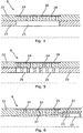
- Fig. 4 shows a cross-sectional view of the inflow device 8 along an axial extension of the inflow device 8 being concentric with the axial extension of the casing.
- the inflow device 8 comprises an outer sleeve 22 and an inner sleeve 23, and the inner sleeve 23 may be movable in relation to the outer sleeve 22.
- the cross-sectional view is taken along a row of inflow openings 24 arranged in the extension of the inflow device 8. In this row, there are seven inflow openings 24.
- the inflow area of the inflow device is inter alia constituted by these inflow openings 24 each having an opening area.
- the inflow device 8 has several rows of inflow openings, the total opening area of all these rows provides the total available inflow area of the inflow device.
- the inflow openings 24 are in fluid connection with the inner opening 25 of the second inner sleeve 23 so that fluid from the reservoir may flow in through the inflow device 8.
- the inner opening 25 is shown as a through-going groove extending in the axial extension of the inflow device 8.
- the inner opening 25 has a larger extension than the inflow openings 24 to ensure that the inner opening 25, when being aligned with the inflow openings, does not prevent the fluid from flowing.
- a screen 26 or filter is arranged on the outside of the inflow openings.
- FIG. 5 Another embodiment of the inflow device 8 is shown in Fig. 5 in a cross-sectional view along an axial extension of the inflow device 8.
- the inflow device 8 also comprises the outer sleeve 22 and the inner sleeve 23 which are movable in relation to each other.
- the inflow openings 24 are in fluid connection with the inner openings 25 of the second inner sleeve 23 to allow fluid from the reservoir to flow in through the inflow device 8.
- the inner openings 25 are shown as seven through-going holes being aligned with the inflow openings 24 of the outer sleeve.
- the inner openings 25 have a larger extension than each of the inflow openings 24 so they do not prevent the fluid from flowing.
- a screen 26 or filter is arranged on the outside of the inflow openings 24.
- FIG. 6 An additional embodiment of the inflow device 8 is shown in Fig. 6 in a cross-sectional view along a row of inflow openings 24 arranged in the extension of the inflow device 8.
- the inflow openings 24 terminate in an axially extending channel 27 arranged in the wall of the outer sleeve 22.
- the axial channel 27 abuts an axial channel 55 arranged in the inner sleeve 23, whereby the inflow openings 24 are in fluid communication with the inner opening 25 via the two axial channels 27, 55, respectively.
- a screen 26 or filter is arranged on the outside of the inflow openings 24.
- the embodiment of the inflow device 8 shown in Fig. 6 will be described further in connection with Fig. 9 below.
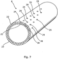
- the inflow device 8 of Fig. 4 is shown in perspective in Fig. 7 .
- the inflow device 8 comprises the outer sleeve 22 and the inner sleeve 23, wherein the inner sleeve 23 is movable in relation to the outer sleeve 22 by rotation.
- Four rows of inflow openings 24, 28, 29, 30 are arranged adjacent to each other and along the axial extension of the inflow device 8.
- the first row has seven inflow openings 24, as shown in the cross-sectional view in Fig. 4 .
- the second row has six inflow openings 28.
- the third row has four inflow openings 29, and the fourth row has two inflow openings 30.
- the inflow openings 24, 28, 29, 30 of the four rows constitute the inflow area of the inflow device 8.
- the inflow device may have a different number of rows and a different number of inflow openings in each row.
- the embodiment shown in Fig. 7 is one configuration of the inflow device 8.
- the inner sleeve 23 is shown in Fig. 7 with four inner openings 25 visible in cross-section, and the openings 25 are each aligned with an inflow opening in the row of inflow openings 24 arranged in the outer sleeve 22.
- the inflow device 8 may have a different number of inner openings and different positions along the periphery of the inner sleeve.
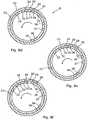
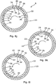
- Figs. 8a to 8o show a sequence of different adjustments to different positions of the inflow device in relation to the desired inflow volume rate of the inflow device 8.
- the inflow device 8 comprises an inner sleeve 23 or tubular which is rotatable within the outer sleeve 22 or tubular.
- the inflow device 8 is shown in a cross-sectional view of a radial extension of the inflow device 8.
- the outer sleeve 22 has four rows of inflow openings 24, 28, 29, 30. In the first row 24, there are seven inflow openings, as shown in Fig. 7 , in the second row 28, there are six openings, in the third row 29, there are four openings, and in the fourth row, there are two openings. In Fig.
- the inner sleeve 23 has ten inner openings 25, 31, 32, 33, 34, 35, 36, 37, 38, 39 in the form of grooves, the grooves being shown in Fig. 4 , and the openings are arranged along the periphery of the inner sleeve 23.
- the inner openings 25, 31, 32, 33, 34, 35, 36, 37, 38, 39 are arranged with predetermined distances between them so that each row of outer inflow openings 24 can optionally be opened or closed by rotating the inner sleeve 23, which will be further described below.
- Fig. 8b the inner sleeve 23 is rotated slightly to the right, whereby the inner opening 25 is aligned with the first row of inflow openings 24, the inner opening 31 is aligned with the row of inflow openings 29, and the inner opening 32 is aligned with the row of inflow openings 30.
- the rows of inflow openings 24, 29, 30 are open and the row of inflow openings 28 is closed, resulting in thirteen openings being open.
- Fig. 8c the inner sleeve 23 is rotated slightly to the left, whereby the inner opening 31 is aligned with the row of inflow openings 28, the inner opening 32 is aligned with the row of inflow openings 29, and the inner opening 33 is aligned with the row of inflow openings 30.
- the rows of inflow openings 28, 29, 30 are open and the row of inflow openings 24 is closed, resulting in twelve openings being open.
- Fig. 8d the inner sleeve 23 is rotated slightly to the left in relation to the adjustment of Fig. 8c , whereby the inner opening 32 is aligned with the row of inflow openings 24, the inner opening 33 is aligned with the row of inflow openings 28, and the inner opening 34 is aligned with the row of inflow openings 29.
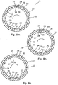
- the rows of inflow openings 24, 28, 29 are open and the row of inflow openings 30 is closed, resulting in seventeen openings being open.
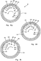
- Fig. 8e the inner sleeve 23 is rotated slightly to the left in relation to the adjustment of Fig. 8d , whereby the inner opening 33 is aligned with the row of inflow openings 24, the inner opening 34 is aligned with the row of inflow openings 28, and the inner opening 35 is aligned with the row of inflow openings 30.
- the rows of inflow openings 24, 28, 30 are open and the row of inflow openings 29 is closed, resulting in fifteen openings being open.
- Fig. 8h the inner sleeve 23 is rotated slightly to the left in relation to the adjustment of Fig. 8g , whereby the inner opening 35 is aligned with the row of inflow openings 24 and the inner opening 36 is aligned with the row of inflow openings 30.
- the rows of inflow openings 24, 30 are open and the rows of inflow openings 28, 29 are closed, resulting in nine openings being open.
- Fig. 8i the inner sleeve 23 is rotated slightly to the left in relation to the adjustment of Fig. 8h , whereby the inner opening 36 is aligned with the row of inflow openings 28 and the inner opening 37 is aligned with the row of inflow openings 30.
- the rows of inflow openings 28, 30 are open and the rows of inflow openings 24, 29 are closed, resulting in eight openings being open.
- Fig. 8j the inner sleeve 23 is rotated slightly to the left in relation to the adjustment of Fig. 8i , whereby the inner opening 36 is aligned with the row of inflow openings 24 and the inner opening 37 is aligned with the row of inflow openings 29.
- the rows of inflow openings 24, 29 are open and the rows of inflow openings 28, 30 are closed, and this adjustment thus results in the same position as in Fig. 8f .
- Figs. 8a-8o shows different flow capacities of the inflow device 8, resulting in fourteen different volume rates. Even though some possible adjustments of the inflow device 8 are not shown in Figs. 8a-8o , it is evident for the skilled person that the configuration of the inflow device 8 makes it possible to open and close all rows of inflow openings independently of each other by rotating the inner sleeve into the intended position.
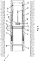
- Fig. 9 shows a longitudinal cross-sectional view of another embodiment of an inflow device 8.
- the inflow device 8 comprises a first sleeve or tubular 40 having twelve inflow openings 24 in a first wall 41 and twelve first axial channels 27 extending in the first wall 41 from the inflow openings 24 to an outlet 53.
- axial channels is meant that the channels extend in an axial direction in relation to the inflow device 8.
- the inflow device also comprises a second sleeve 42 or tubular having a first end 43 near the outlet 53 and a second end 44 and, in this view, six inner openings 25. Even though the second sleeve 42 or tubular only shows six inner openings 25, the number of inner openings is actually the same as in the first sleeve 40 or tubular, i.e. 12 inner openings.
- the second sleeve 42 or tubular is rotatable within the first sleeve 40 or tubular, and the second sleeve 42 has a second wall 45 having twelve second axial channels (not shown) extending in the second wall 45 from the first end 43 to the inner opening 25.
- each inner opening 25 has its own second axial channel.
- the second sleeve 42 or tubular is arranged in an inner circumferential recess 46 in the first wall 41 of the first sleeve 40 or tubular, meaning that when the second sleeve 42 or tubular is arranged in the recess, the second sleeve 42 or tubular will not decrease the overall inner diameter of the inflow device and thereby of the production casing.
- the second sleeve 42 or tubular is rotatable in relation to the first sleeve 40 or tubular at least between a first position, in which the first channel 27 and second channel (not shown) are aligned to allow fluid to flow from the reservoir into the production casing via the first end 43 of the second sleeve 42 or tubular, and a second position (the position shown in Fig. 9 ), in which the first channel 27 and second channel (not shown) are not aligned, meaning that fluid is prevented from flowing into the production casing.
- the inflow device 8 also comprises a first packer 47 which is arranged between the first sleeve 40 or tubular and the first end 43 of the second sleeve 42 or tubular.
- the packer 47 extends around the inner circumferential recess 46 and has an inner diameter which is substantially the same as that of the second sleeve or tubular.
- the packer 47 has a number of through-going packer channels 48 corresponding to the number of first axial channels, i.e. in this embodiment twelve, the packer channels 48 being aligned with the first axial channels 27.
- the packer is fixedly connected with the first sleeve or tubular so that the packer channels 48 are fluidly connected with first axial channels.
- the packer is ringshaped, and the through-going packer channels 48 extend through the packer along the axial extension of the first sleeve or tubular.
- the packer 47 is preferably made of ceramics, whereby it is possible to make the contact surfaces of the packer 47 smooth, which enhances the sealing properties of the packer 47, since the smooth contact surface may be pressed closer to the opposite surface which is the first end 43 of the second sleeve 42 or tubular.
- the packer may be made of metal, composites, polymers or the like.
- a second packer 49 is arranged between the first sleeve 40 or tubular and the second end 44 of the second sleeve 42 or tubular.
- the second packer is omitted, whereby the second end 44 of the second sleeve 42 or tubular faces the first wall of the first sleeve 40 or tubular.
- a first spring element 50 is arranged between the first packer 47 and the first sleeve 40 or tubular. The spring element 50 thus forces the first packer against the second sleeve 42 to provide a seal therebetween.
- the second sleeve 42 or tubular may comprise at least one recess 51 accessible from within, the recess 51 being adapted to receive a key tool (not shown) for rotating the second sleeve 42 or tubular in relation to the first sleeve 40 or tubular.
- the adjustment of the inflow devices 8, 9 may be performed manually, e.g. by inserting a downhole tool having a key tool into the production casing and moving the downhole tool to the inflow device which needs to be adjusted.
- the inflow devices 8, 9 may also be operated by a magnetic source.
- the inflow device 8 of Fig. 7 has an inner sleeve 23 rotating in relation to an outer sleeve 22, and in Fig. 10 , the inner sleeve 23 slides axially in relation to the outer sleeve 22.
- the inner sleeve 23 slides in a recess in the outer sleeve 22, as shown in Fig. 11 where the inner sleeve covers three of the four rows shown in
- the first row comprises eight inflow openings 24, the second row comprises six inflow openings 24, the third row comprises four inflow openings 24, and the fourth row comprises two inflow openings 24.
- the number of inflow openings 24 which the fluid may flow through may be varied in the same manner as in the embodiment of the inflow device 8 shown in Fig. 7 .
- the inflow device may have a different number of rows and a different number of inflow openings in each row.
- the embodiment shown in Figs. 9 and 10 is only one configuration of the inflow device 8.
- Fig. 1 shows the production casing comprising annular barriers, each annular barrier being adapted for expansion in an annulus 52 between a production casing and an inside wall 54 of a borehole 55 downhole.
- Each annular barrier comprises a tubular part 57 for mounting as part of the production casing and an expandable sleeve 58 surrounding the tubular part.
- Each end 59, 60 of the expandable sleeve is fastened to the tubular part by means of a connection part 72. At least one end is slidably connected with the tubular part.
- the expandable sleeve surrounds the tubular part and defines an annular barrier space 73 between the tubular part and the expandable sleeve.
- the annular barrier further comprises an aperture 71 in the tubular part for letting fluid into the annular barrier space to expand the sleeve.
- the annular barriers are arranged separating the first reservoir zone 6 and the second reservoir zone 7 so that three annular barriers provide two reservoir zones.
- the expandable sleeve, the tubular part and the connection parts are made of metal.
- the inflow devices may be remotely adjustable, e.g. by wireline or wireless control.
- the inflow device 8 is adapted to be inserted and form part of the production casing 3, thus forming a cased completion (not shown). Accordingly, the ends of the inflow device 8 are adapted to be connected with another casing element by conventional connection means, for instance by means of a threaded connection.
- the outer openings are shown as openings per se.
- the outer openings may comprise flow restrictors, throttles or valves, such as inflow control valves (not shown).
- the inner sleeve may be slidably movable in relation to the outer sleeve.
- fluid or well fluid any kind of fluid that may be present in oil or gas wells downhole, such as natural gas, oil, oil mud, crude oil, water, etc.
- gas is meant any kind of gas composition present in a well, completion, or open hole
- oil is meant any kind of oil composition, such as crude oil, an oil-containing fluid, etc.
- Gas, oil, and water fluids may thus all comprise other elements or substances than gas, oil, and/or water, respectively.
- a casing any kind of pipe, tubing, tubular, liner, string etc. used downhole in relation to oil or natural gas production.
- a downhole tractor can be used to push the tools all the way into position in the well.
- a downhole tractor is any kind of driving tool capable of pushing or pulling tools in a well downhole, such as a Well Tractor®.
Landscapes
- Geology (AREA)
- Life Sciences & Earth Sciences (AREA)
- Engineering & Computer Science (AREA)
- Mining & Mineral Resources (AREA)
- Environmental & Geological Engineering (AREA)
- Fluid Mechanics (AREA)
- Physics & Mathematics (AREA)
- General Life Sciences & Earth Sciences (AREA)
- Geochemistry & Mineralogy (AREA)
- Physical Or Chemical Processes And Apparatus (AREA)
- Organic Low-Molecular-Weight Compounds And Preparation Thereof (AREA)
- Production Of Liquid Hydrocarbon Mixture For Refining Petroleum (AREA)
- Measuring Volume Flow (AREA)
- Feeding, Discharge, Calcimining, Fusing, And Gas-Generation Devices (AREA)
Claims (15)
- Système de production (1) pour produire des hydrocarbures à partir d'un puits (2), comprenant :- un tubage de production (3),- une première zone de réservoir (6) comprenant au moins un premier fluide (10) s'étendant le long et à l'extérieur d'une partie du tubage de production (3),- une seconde zone de réservoir (7) comprenant au moins un second fluide (11), s'étendant le long et à l'extérieur d'une autre partie du tubage de production (3),- un premier dispositif d'entrée (8) agencé dans la première zone de réservoir (6) ayant une première zone d'entrée et étant adapté pour laisser le premier fluide (10) dans le tubage de production (3) à une première vitesse en volume (V1), et- un second dispositif d'entrée (9) agencé dans la seconde zone de réservoir (7), ayant une seconde zone d'entrée et étant adapté pour laisser le second fluide (11) dans le tubage de production (3) à une seconde vitesse en volume (V2),dans lequel les première et seconde zones d'entrée des dispositifs d'entrée (8, 9) sont ajustables, moyennant quoi les premier et second dispositifs d'entrée (8, 9) peuvent être ajustés de sorte que la première vitesse en volume (V1) est égale ou supérieure à la seconde vitesse en volume (V2), et dans lequel le dispositif d'entrée (8, 9) comprend un premier manchon externe (22) et un second manchon interne (23) mobiles l'un par rapport à l'autre, caractérisé en ce que le premier manchon externe (22) a des ouvertures d'entrée externes (24, 28, 29, 30) agencées en rangées avec un nombre différent d'ouvertures dans chaque rangée, et en ce que le second manchon interne (23) a des ouvertures internes (25, 31, 32, 33, 34, 35, 36, 37, 38, 39), moyennant quoi la zone d'entrée du dispositif d'entrée (8, 9) est ajustable en ce que les ouvertures internes (25, 31, 32, 33, 34, 35, 36, 37, 38, 39) du second manchon interne (23) peuvent être déplacées et alignées par rapport aux ouvertures externes (24, 28, 29, 30) du premier manchon (22).
- Système de production (1) selon la revendication 1, dans lequel les ouvertures internes sont agencées avec une distance entre elles qui est différente d'une distance entre les ouvertures externes (24, 28, 29, 30), moyennant quoi la zone d'entrée du dispositif d'entrée (8, 9) est ajustable en ce que les ouvertures internes (25, 31, 32, 33, 34, 35, 36, 37, 38, 39) du second manchon interne (23) peuvent être déplacées et alignées par rapport aux ouvertures externes (24, 28, 29, 30) du premier manchon (22).
- Système de production (1) selon la revendication 1 ou 2, dans lequel les ouvertures internes du manchon interne peuvent être agencées avec des distances circonférentielles prédéterminées entre elles de sorte que chaque rangée d'ouvertures d'entrée externes peut facultativement être ouverte ou fermée en déplaçant le manchon interne.
- Système de production (1) selon l'une quelconque des revendications précédentes, comprenant en outre une unité de surveillance (4) adaptée pour mesurer un résultat de production du puits (2).
- Système de production (1) selon la revendication 4, dans lequel l'unité de surveillance (4) est adaptée pour mesurer une teneur en eau du résultat de production de sorte que les dispositifs d'entrée (8, 9) peuvent être ajustés pour obtenir un optimum entre le résultat de production et la teneur en eau.
- Système de production (1) selon la revendication 4 ou 5, dans lequel l'unité de surveillance (4) est adaptée pour mesurer une vitesse en volume du résultat de production et/ou une pression au sommet du puits (2) de sorte que les dispositifs d'entrée (8, 9) peuvent être ajustés en fonction de la vitesse en volume et/ou de la pression mesurée au sommet du puits (2).
- Système de production (1) selon l'une quelconque des revendications précédentes, dans lequel les zones de réservoirs (6, 7) sont séparées par des barrières annulaires (12).
- Système de production (1) selon l'une quelconque des revendications précédentes, dans lequel le premier fluide (10) est du pétrole et le second fluide (11) est de l'eau ou du gaz.
- Système de production (1) selon l'une quelconque des revendications précédentes, dans lequel le dispositif d'entrée comprend une première garniture d'étanchéité (47), le second manchon est agencé dans un évidement (46) du premier manchon, et la première garniture d'étanchéité est agencée entre le premier manchon et le second manchon.
- Système de production (1) selon la revendication 9, dans lequel la garniture d'étanchéité s'étend autour de l'évidement circonférentiel interne (46) et a un diamètre interne qui est sensiblement identique à celui du second manchon.
- Système de production (1) selon l'une quelconque des revendications précédentes, dans lequel le tubage de production comprend des barrières annulaires, chaque barrière annulaire étant adaptée pour être expansée dans un espace annulaire (52) entre le tubage de production et une paroi interne (54) d'un sondage (55) de fond de trou, et chaque barrière annulaire comprenant :- une partie tubulaire (57) destinée à être montée comme faisant partie du tubage de production,- un manchon expansible (58) entourant la partie tubulaire, chaque extrémité (59, 60) du manchon expansible étant fixée à la partie tubulaire au moyen d'une partie de raccordement (72),- un espace de barrière annulaire (73) entre la partie tubulaire et le manchon expansible, et- une ouverture (71) dans la partie tubulaire pour laisser le fluide dans l'espace de barrière annulaire pour expanser le manchon,dans lequel les barrières annulaires sont agencées, séparant la première zone de réservoir (6) et la seconde zone de réservoir (7).
- Complétion de puits comprenant le système de production (1) selon l'une quelconque des revendications 1 à 11 et une tête de puits (5).
- Procédé de production pour produire des hydrocarbures à partir d'un puits (2) au moyen du système de production selon l'une quelconque des revendications 1 à 11, comprenant les étapes consistant à :- identifier une première zone de réservoir (6) comprenant au moins un premier fluide (10),- identifier une seconde zone de réservoir (7) comprenant au moins un second fluide (11),- ouvrir un premier dispositif d'entrée (8) dans la première zone (6) pour laisser le au moins un premier fluide (10) dans un tubage de production (3) à une première vitesse en volume (V1),- ouvrir un second dispositif d'entrée (9) dans la seconde zone (7) pour laisser le au moins un second fluide (11) dans le tubage de production (3) à une seconde vitesse en volume (V2),- surveiller un résultat de production du puits (2), et- ajuster les premier et second dispositifs d'entrée (8, 9) basés sur le résultat de production de sorte que la première vitesse en volume (V1) est égale ou supérieure à la seconde vitesse en volume (V2) ou de sorte que la seconde vitesse en volume est supérieure à la première vitesse en volume.
- Procédé selon la revendication 13, dans lequel l'étape de surveillance comprend une ou plusieurs étapes consistant à :- mesurer une pression au sommet du puits,- mesurer une vitesse en volume du résultat de production au sommet du puits, et/ou- mesurer une teneur en eau du résultat de production au sommet du puits.
- Procédé selon la revendication 13 ou 14, dans lequel l'étape consistant à ajuster les premier et second dispositifs d'entrée comprend en outre l'étape consistant à ajuster au moins l'un des dispositifs d'entrée (8, 9) en fonction de la pression mesurée, de la vitesse en volume et/ou de la teneur en eau au sommet du puits.
Priority Applications (1)
| Application Number | Priority Date | Filing Date | Title |
|---|---|---|---|
| EP12806485.4A EP2795052B1 (fr) | 2011-12-23 | 2012-12-21 | Système de production pour produire des hydrocarbures à partir d'un puits |
Applications Claiming Priority (3)
| Application Number | Priority Date | Filing Date | Title |
|---|---|---|---|
| EP11195580.3A EP2607616A1 (fr) | 2011-12-23 | 2011-12-23 | Système de production permettant de produire des hydrocarbures à partir d'un puits |
| PCT/EP2012/076541 WO2013092945A1 (fr) | 2011-12-23 | 2012-12-21 | Système de production pour produire des hydrocarbures à partir d'un puits |
| EP12806485.4A EP2795052B1 (fr) | 2011-12-23 | 2012-12-21 | Système de production pour produire des hydrocarbures à partir d'un puits |
Publications (2)
| Publication Number | Publication Date |
|---|---|
| EP2795052A1 EP2795052A1 (fr) | 2014-10-29 |
| EP2795052B1 true EP2795052B1 (fr) | 2016-07-20 |
Family
ID=47435990
Family Applications (2)
| Application Number | Title | Priority Date | Filing Date |
|---|---|---|---|
| EP11195580.3A Withdrawn EP2607616A1 (fr) | 2011-12-23 | 2011-12-23 | Système de production permettant de produire des hydrocarbures à partir d'un puits |
| EP12806485.4A Not-in-force EP2795052B1 (fr) | 2011-12-23 | 2012-12-21 | Système de production pour produire des hydrocarbures à partir d'un puits |
Family Applications Before (1)
| Application Number | Title | Priority Date | Filing Date |
|---|---|---|---|
| EP11195580.3A Withdrawn EP2607616A1 (fr) | 2011-12-23 | 2011-12-23 | Système de production permettant de produire des hydrocarbures à partir d'un puits |
Country Status (10)
| Country | Link |
|---|---|
| US (1) | US20140352956A1 (fr) |
| EP (2) | EP2607616A1 (fr) |
| CN (1) | CN104254664A (fr) |
| AU (1) | AU2012356949B2 (fr) |
| BR (1) | BR112014013982A2 (fr) |
| CA (1) | CA2858643A1 (fr) |
| DK (1) | DK2795052T3 (fr) |
| MX (1) | MX342054B (fr) |
| RU (1) | RU2014127616A (fr) |
| WO (1) | WO2013092945A1 (fr) |
Families Citing this family (10)
| Publication number | Priority date | Publication date | Assignee | Title |
|---|---|---|---|---|
| CA2810266C (fr) | 2010-09-09 | 2016-05-03 | National Oilwell Varco, L.P. | Appareil de forage rotatif de fond de trou comportant des elements en interface avec les formations et systeme de commande |
| US8869916B2 (en) | 2010-09-09 | 2014-10-28 | National Oilwell Varco, L.P. | Rotary steerable push-the-bit drilling apparatus with self-cleaning fluid filter |
| BR112017017200B1 (pt) * | 2015-03-24 | 2022-06-28 | Halliburton Energy Services, Inc. | Conjunto de controle de fluxo, sistema de poço e método |
| JP6618813B2 (ja) * | 2016-01-21 | 2019-12-11 | 株式会社大阪防水建設社 | 地下水サンプリング方法 |
| US10619474B2 (en) | 2017-11-14 | 2020-04-14 | Saudi Arabian Oil Company | Remotely operated inflow control valve |
| RU179815U1 (ru) * | 2018-01-10 | 2018-05-24 | Владимир Александрович Чигряй | Устройство регулирования притока флюида |
| RU178922U1 (ru) * | 2018-01-10 | 2018-04-23 | Владимир Александрович Чигряй | Устройство регулирования притока флюида |
| DE102020117596A1 (de) | 2020-07-03 | 2022-01-05 | Fraunhofer-Gesellschaft zur Förderung der angewandten Forschung eingetragener Verein | Siebfilter für Geotechnikanlagen |
| US11788380B2 (en) * | 2021-10-20 | 2023-10-17 | Saudi Arabian Oil Company | Installation of sliding sleeve with shifting profile in passive inflow control devices |
| CN114645543B (zh) * | 2022-04-27 | 2023-01-24 | 中国矿业大学 | 一种岩溶地区桩孔定点注浆方法和定点注浆装置 |
Family Cites Families (14)
| Publication number | Priority date | Publication date | Assignee | Title |
|---|---|---|---|---|
| US3993130A (en) * | 1975-05-14 | 1976-11-23 | Texaco Inc. | Method and apparatus for controlling the injection profile of a borehole |
| US4691778A (en) * | 1987-02-09 | 1987-09-08 | Pyne R David G | Downhole water flow controller for aquifer storage recovery wells |
| US4858691A (en) * | 1988-06-13 | 1989-08-22 | Baker Hughes Incorporated | Gravel packing apparatus and method |
| GB9025230D0 (en) * | 1990-11-20 | 1991-01-02 | Framo Dev Ltd | Well completion system |
| US5664628A (en) * | 1993-05-25 | 1997-09-09 | Pall Corporation | Filter for subterranean wells |
| US5642781A (en) * | 1994-10-07 | 1997-07-01 | Baker Hughes Incorporated | Multi-passage sand control screen |
| US5624560A (en) * | 1995-04-07 | 1997-04-29 | Baker Hughes Incorporated | Wire mesh filter including a protective jacket |
| US6873267B1 (en) * | 1999-09-29 | 2005-03-29 | Weatherford/Lamb, Inc. | Methods and apparatus for monitoring and controlling oil and gas production wells from a remote location |
| US6644406B1 (en) * | 2000-07-31 | 2003-11-11 | Mobil Oil Corporation | Fracturing different levels within a completion interval of a well |
| US6978840B2 (en) * | 2003-02-05 | 2005-12-27 | Halliburton Energy Services, Inc. | Well screen assembly and system with controllable variable flow area and method of using same for oil well fluid production |
| BRPI0713396B1 (pt) * | 2006-07-03 | 2017-12-26 | Bj Services Company | Catraca steering mechanism |
| US7832473B2 (en) * | 2007-01-15 | 2010-11-16 | Schlumberger Technology Corporation | Method for controlling the flow of fluid between a downhole formation and a base pipe |
| US8210258B2 (en) * | 2009-12-22 | 2012-07-03 | Baker Hughes Incorporated | Wireline-adjustable downhole flow control devices and methods for using same |
| GB2495504B (en) * | 2011-10-11 | 2018-05-23 | Halliburton Mfg & Services Limited | Downhole valve assembly |
-
2011
- 2011-12-23 EP EP11195580.3A patent/EP2607616A1/fr not_active Withdrawn
-
2012
- 2012-12-21 WO PCT/EP2012/076541 patent/WO2013092945A1/fr active Application Filing
- 2012-12-21 DK DK12806485.4T patent/DK2795052T3/en active
- 2012-12-21 CA CA2858643A patent/CA2858643A1/fr not_active Abandoned
- 2012-12-21 AU AU2012356949A patent/AU2012356949B2/en not_active Ceased
- 2012-12-21 MX MX2014006957A patent/MX342054B/es active IP Right Grant
- 2012-12-21 CN CN201280060532.3A patent/CN104254664A/zh active Pending
- 2012-12-21 BR BR112014013982A patent/BR112014013982A2/pt not_active IP Right Cessation
- 2012-12-21 EP EP12806485.4A patent/EP2795052B1/fr not_active Not-in-force
- 2012-12-21 US US14/363,880 patent/US20140352956A1/en not_active Abandoned
- 2012-12-21 RU RU2014127616A patent/RU2014127616A/ru not_active Application Discontinuation
Also Published As
| Publication number | Publication date |
|---|---|
| AU2012356949A1 (en) | 2014-07-24 |
| WO2013092945A1 (fr) | 2013-06-27 |
| DK2795052T3 (en) | 2016-11-14 |
| MX2014006957A (es) | 2014-09-01 |
| MX342054B (es) | 2016-09-12 |
| US20140352956A1 (en) | 2014-12-04 |
| BR112014013982A2 (pt) | 2017-06-13 |
| RU2014127616A (ru) | 2016-02-10 |
| CN104254664A (zh) | 2014-12-31 |
| EP2795052A1 (fr) | 2014-10-29 |
| EP2607616A1 (fr) | 2013-06-26 |
| CA2858643A1 (fr) | 2013-06-27 |
| AU2012356949B2 (en) | 2015-09-03 |
Similar Documents
| Publication | Publication Date | Title |
|---|---|---|
| EP2795052B1 (fr) | Système de production pour produire des hydrocarbures à partir d'un puits | |
| CA2501839C (fr) | Manchon coulissant actionne par une soupape hydraulique d'entrainement pas a pas | |
| US8931557B2 (en) | Wellbore servicing assemblies and methods of using the same | |
| US20050034875A1 (en) | Valves for Use in Wells | |
| US20060201677A1 (en) | Multilateral production apparatus and method | |
| US8668018B2 (en) | Selective dart system for actuating downhole tools and methods of using same | |
| US10443347B2 (en) | Downhole completion tool | |
| AU2011384179A1 (en) | Unequal load collet and method of use | |
| WO2013101715A2 (fr) | Outil de fond comprenant une section pouvant être pompée | |
| US9650864B2 (en) | Remotely operated production valve and method | |
| US20180266218A1 (en) | Annular flow rings for sand control screen assemblies | |
| US9163493B2 (en) | Wellbore servicing assemblies and methods of using the same | |
| EP2815067B1 (fr) | Dérivation de fluide pour un tube de dispositif de régulation de débit entrant | |
| EP2245258B1 (fr) | Section améliorée de colonne de production | |
| US7992637B2 (en) | Reverse flow in-flow control device | |
| WO2014200469A1 (fr) | Joint etanche aux fluides a haute pression et haute temperature utilisant une serie de bagues annulaires | |
| RU2728626C1 (ru) | Устройство с узлом перекрестного потока для управления потоком внутри скважины | |
| US20130255962A1 (en) | Downhole Circulating Valve Having a Metal-To-Metal Seal and Method for Operating Same | |
| CA2613115C (fr) | Systeme pour commander le debit du fluide dans un puits | |
| WO2014004561A2 (fr) | Procédé et appareil pour injecter un gaz dans un réservoir | |
| US8763707B2 (en) | Downhole circulating valve having a metal-to-metal seal | |
| WO2013151534A1 (fr) | Vanne circulante de fond de puits comprenant un joint métal-métal et procédé de fonctionnement |
Legal Events
| Date | Code | Title | Description |
|---|---|---|---|
| PUAI | Public reference made under article 153(3) epc to a published international application that has entered the european phase |
Free format text: ORIGINAL CODE: 0009012 |
|
| 17P | Request for examination filed |
Effective date: 20140702 |
|
| AK | Designated contracting states |
Kind code of ref document: A1 Designated state(s): AL AT BE BG CH CY CZ DE DK EE ES FI FR GB GR HR HU IE IS IT LI LT LU LV MC MK MT NL NO PL PT RO RS SE SI SK SM TR |
|
| DAX | Request for extension of the european patent (deleted) | ||
| GRAP | Despatch of communication of intention to grant a patent |
Free format text: ORIGINAL CODE: EPIDOSNIGR1 |
|
| INTG | Intention to grant announced |
Effective date: 20151012 |
|
| GRAS | Grant fee paid |
Free format text: ORIGINAL CODE: EPIDOSNIGR3 |
|
| INTG | Intention to grant announced |
Effective date: 20160216 |
|
| GRAA | (expected) grant |
Free format text: ORIGINAL CODE: 0009210 |
|
| AK | Designated contracting states |
Kind code of ref document: B1 Designated state(s): AL AT BE BG CH CY CZ DE DK EE ES FI FR GB GR HR HU IE IS IT LI LT LU LV MC MK MT NL NO PL PT RO RS SE SI SK SM TR |
|
| REG | Reference to a national code |
Ref country code: GB Ref legal event code: FG4D |
|
| REG | Reference to a national code |
Ref country code: CH Ref legal event code: EP |
|
| REG | Reference to a national code |
Ref country code: IE Ref legal event code: FG4D |
|
| REG | Reference to a national code |
Ref country code: AT Ref legal event code: REF Ref document number: 814264 Country of ref document: AT Kind code of ref document: T Effective date: 20160815 |
|
| REG | Reference to a national code |
Ref country code: DE Ref legal event code: R096 Ref document number: 602012020814 Country of ref document: DE |
|
| REG | Reference to a national code |
Ref country code: NL Ref legal event code: FP |
|
| REG | Reference to a national code |
Ref country code: LT Ref legal event code: MG4D |
|
| REG | Reference to a national code |
Ref country code: NO Ref legal event code: T2 Effective date: 20160720 Ref country code: DK Ref legal event code: T3 Effective date: 20161110 |
|
| REG | Reference to a national code |
Ref country code: FR Ref legal event code: PLFP Year of fee payment: 5 |
|
| REG | Reference to a national code |
Ref country code: AT Ref legal event code: MK05 Ref document number: 814264 Country of ref document: AT Kind code of ref document: T Effective date: 20160720 |
|
| PG25 | Lapsed in a contracting state [announced via postgrant information from national office to epo] |
Ref country code: FI Free format text: LAPSE BECAUSE OF FAILURE TO SUBMIT A TRANSLATION OF THE DESCRIPTION OR TO PAY THE FEE WITHIN THE PRESCRIBED TIME-LIMIT Effective date: 20160720 Ref country code: HR Free format text: LAPSE BECAUSE OF FAILURE TO SUBMIT A TRANSLATION OF THE DESCRIPTION OR TO PAY THE FEE WITHIN THE PRESCRIBED TIME-LIMIT Effective date: 20160720 Ref country code: RS Free format text: LAPSE BECAUSE OF FAILURE TO SUBMIT A TRANSLATION OF THE DESCRIPTION OR TO PAY THE FEE WITHIN THE PRESCRIBED TIME-LIMIT Effective date: 20160720 Ref country code: IT Free format text: LAPSE BECAUSE OF FAILURE TO SUBMIT A TRANSLATION OF THE DESCRIPTION OR TO PAY THE FEE WITHIN THE PRESCRIBED TIME-LIMIT Effective date: 20160720 Ref country code: IS Free format text: LAPSE BECAUSE OF FAILURE TO SUBMIT A TRANSLATION OF THE DESCRIPTION OR TO PAY THE FEE WITHIN THE PRESCRIBED TIME-LIMIT Effective date: 20161120 Ref country code: LT Free format text: LAPSE BECAUSE OF FAILURE TO SUBMIT A TRANSLATION OF THE DESCRIPTION OR TO PAY THE FEE WITHIN THE PRESCRIBED TIME-LIMIT Effective date: 20160720 |
|
| PGFP | Annual fee paid to national office [announced via postgrant information from national office to epo] |
Ref country code: NL Payment date: 20161215 Year of fee payment: 5 Ref country code: NO Payment date: 20161215 Year of fee payment: 5 Ref country code: GB Payment date: 20161220 Year of fee payment: 5 Ref country code: DK Payment date: 20161222 Year of fee payment: 5 |
|
| PG25 | Lapsed in a contracting state [announced via postgrant information from national office to epo] |
Ref country code: LV Free format text: LAPSE BECAUSE OF FAILURE TO SUBMIT A TRANSLATION OF THE DESCRIPTION OR TO PAY THE FEE WITHIN THE PRESCRIBED TIME-LIMIT Effective date: 20160720 Ref country code: SE Free format text: LAPSE BECAUSE OF FAILURE TO SUBMIT A TRANSLATION OF THE DESCRIPTION OR TO PAY THE FEE WITHIN THE PRESCRIBED TIME-LIMIT Effective date: 20160720 Ref country code: AT Free format text: LAPSE BECAUSE OF FAILURE TO SUBMIT A TRANSLATION OF THE DESCRIPTION OR TO PAY THE FEE WITHIN THE PRESCRIBED TIME-LIMIT Effective date: 20160720 Ref country code: PT Free format text: LAPSE BECAUSE OF FAILURE TO SUBMIT A TRANSLATION OF THE DESCRIPTION OR TO PAY THE FEE WITHIN THE PRESCRIBED TIME-LIMIT Effective date: 20161121 Ref country code: BE Free format text: LAPSE BECAUSE OF FAILURE TO SUBMIT A TRANSLATION OF THE DESCRIPTION OR TO PAY THE FEE WITHIN THE PRESCRIBED TIME-LIMIT Effective date: 20160720 Ref country code: PL Free format text: LAPSE BECAUSE OF FAILURE TO SUBMIT A TRANSLATION OF THE DESCRIPTION OR TO PAY THE FEE WITHIN THE PRESCRIBED TIME-LIMIT Effective date: 20160720 Ref country code: GR Free format text: LAPSE BECAUSE OF FAILURE TO SUBMIT A TRANSLATION OF THE DESCRIPTION OR TO PAY THE FEE WITHIN THE PRESCRIBED TIME-LIMIT Effective date: 20161021 Ref country code: ES Free format text: LAPSE BECAUSE OF FAILURE TO SUBMIT A TRANSLATION OF THE DESCRIPTION OR TO PAY THE FEE WITHIN THE PRESCRIBED TIME-LIMIT Effective date: 20160720 |
|
| PGFP | Annual fee paid to national office [announced via postgrant information from national office to epo] |
Ref country code: FR Payment date: 20161213 Year of fee payment: 5 |
|
| REG | Reference to a national code |
Ref country code: DE Ref legal event code: R097 Ref document number: 602012020814 Country of ref document: DE |
|
| PG25 | Lapsed in a contracting state [announced via postgrant information from national office to epo] |
Ref country code: RO Free format text: LAPSE BECAUSE OF FAILURE TO SUBMIT A TRANSLATION OF THE DESCRIPTION OR TO PAY THE FEE WITHIN THE PRESCRIBED TIME-LIMIT Effective date: 20160720 Ref country code: EE Free format text: LAPSE BECAUSE OF FAILURE TO SUBMIT A TRANSLATION OF THE DESCRIPTION OR TO PAY THE FEE WITHIN THE PRESCRIBED TIME-LIMIT Effective date: 20160720 |
|
| PGFP | Annual fee paid to national office [announced via postgrant information from national office to epo] |
Ref country code: DE Payment date: 20161222 Year of fee payment: 5 |
|
| PLBE | No opposition filed within time limit |
Free format text: ORIGINAL CODE: 0009261 |
|
| STAA | Information on the status of an ep patent application or granted ep patent |
Free format text: STATUS: NO OPPOSITION FILED WITHIN TIME LIMIT |
|
| PG25 | Lapsed in a contracting state [announced via postgrant information from national office to epo] |
Ref country code: BG Free format text: LAPSE BECAUSE OF FAILURE TO SUBMIT A TRANSLATION OF THE DESCRIPTION OR TO PAY THE FEE WITHIN THE PRESCRIBED TIME-LIMIT Effective date: 20161020 Ref country code: SK Free format text: LAPSE BECAUSE OF FAILURE TO SUBMIT A TRANSLATION OF THE DESCRIPTION OR TO PAY THE FEE WITHIN THE PRESCRIBED TIME-LIMIT Effective date: 20160720 Ref country code: CZ Free format text: LAPSE BECAUSE OF FAILURE TO SUBMIT A TRANSLATION OF THE DESCRIPTION OR TO PAY THE FEE WITHIN THE PRESCRIBED TIME-LIMIT Effective date: 20160720 Ref country code: SM Free format text: LAPSE BECAUSE OF FAILURE TO SUBMIT A TRANSLATION OF THE DESCRIPTION OR TO PAY THE FEE WITHIN THE PRESCRIBED TIME-LIMIT Effective date: 20160720 |
|
| 26N | No opposition filed |
Effective date: 20170421 |
|
| REG | Reference to a national code |
Ref country code: CH Ref legal event code: PL |
|
| PG25 | Lapsed in a contracting state [announced via postgrant information from national office to epo] |
Ref country code: SI Free format text: LAPSE BECAUSE OF FAILURE TO SUBMIT A TRANSLATION OF THE DESCRIPTION OR TO PAY THE FEE WITHIN THE PRESCRIBED TIME-LIMIT Effective date: 20160720 |
|
| PG25 | Lapsed in a contracting state [announced via postgrant information from national office to epo] |
Ref country code: MC Free format text: LAPSE BECAUSE OF FAILURE TO SUBMIT A TRANSLATION OF THE DESCRIPTION OR TO PAY THE FEE WITHIN THE PRESCRIBED TIME-LIMIT Effective date: 20160720 |
|
| REG | Reference to a national code |
Ref country code: IE Ref legal event code: MM4A |
|
| PG25 | Lapsed in a contracting state [announced via postgrant information from national office to epo] |
Ref country code: CH Free format text: LAPSE BECAUSE OF NON-PAYMENT OF DUE FEES Effective date: 20161231 Ref country code: LU Free format text: LAPSE BECAUSE OF NON-PAYMENT OF DUE FEES Effective date: 20161221 Ref country code: LI Free format text: LAPSE BECAUSE OF NON-PAYMENT OF DUE FEES Effective date: 20161231 |
|
| PG25 | Lapsed in a contracting state [announced via postgrant information from national office to epo] |
Ref country code: IE Free format text: LAPSE BECAUSE OF NON-PAYMENT OF DUE FEES Effective date: 20161221 |
|
| PG25 | Lapsed in a contracting state [announced via postgrant information from national office to epo] |
Ref country code: HU Free format text: LAPSE BECAUSE OF FAILURE TO SUBMIT A TRANSLATION OF THE DESCRIPTION OR TO PAY THE FEE WITHIN THE PRESCRIBED TIME-LIMIT; INVALID AB INITIO Effective date: 20121221 |
|
| PG25 | Lapsed in a contracting state [announced via postgrant information from national office to epo] |
Ref country code: MK Free format text: LAPSE BECAUSE OF FAILURE TO SUBMIT A TRANSLATION OF THE DESCRIPTION OR TO PAY THE FEE WITHIN THE PRESCRIBED TIME-LIMIT Effective date: 20160720 Ref country code: CY Free format text: LAPSE BECAUSE OF FAILURE TO SUBMIT A TRANSLATION OF THE DESCRIPTION OR TO PAY THE FEE WITHIN THE PRESCRIBED TIME-LIMIT Effective date: 20160720 |
|
| REG | Reference to a national code |
Ref country code: DE Ref legal event code: R119 Ref document number: 602012020814 Country of ref document: DE |
|
| REG | Reference to a national code |
Ref country code: NO Ref legal event code: MMEP |
|
| REG | Reference to a national code |
Ref country code: DK Ref legal event code: EBP Effective date: 20171231 |
|
| REG | Reference to a national code |
Ref country code: NL Ref legal event code: MM Effective date: 20180101 |
|
| GBPC | Gb: european patent ceased through non-payment of renewal fee |
Effective date: 20171221 |
|
| PG25 | Lapsed in a contracting state [announced via postgrant information from national office to epo] |
Ref country code: NL Free format text: LAPSE BECAUSE OF NON-PAYMENT OF DUE FEES Effective date: 20180101 Ref country code: MT Free format text: LAPSE BECAUSE OF NON-PAYMENT OF DUE FEES Effective date: 20161221 |
|
| REG | Reference to a national code |
Ref country code: FR Ref legal event code: ST Effective date: 20180831 |
|
| PG25 | Lapsed in a contracting state [announced via postgrant information from national office to epo] |
Ref country code: DE Free format text: LAPSE BECAUSE OF NON-PAYMENT OF DUE FEES Effective date: 20180703 Ref country code: FR Free format text: LAPSE BECAUSE OF NON-PAYMENT OF DUE FEES Effective date: 20180102 Ref country code: TR Free format text: LAPSE BECAUSE OF FAILURE TO SUBMIT A TRANSLATION OF THE DESCRIPTION OR TO PAY THE FEE WITHIN THE PRESCRIBED TIME-LIMIT Effective date: 20160720 Ref country code: AL Free format text: LAPSE BECAUSE OF FAILURE TO SUBMIT A TRANSLATION OF THE DESCRIPTION OR TO PAY THE FEE WITHIN THE PRESCRIBED TIME-LIMIT Effective date: 20160720 Ref country code: NO Free format text: LAPSE BECAUSE OF NON-PAYMENT OF DUE FEES Effective date: 20171231 |
|
| PG25 | Lapsed in a contracting state [announced via postgrant information from national office to epo] |
Ref country code: GB Free format text: LAPSE BECAUSE OF NON-PAYMENT OF DUE FEES Effective date: 20171221 |
|
| PG25 | Lapsed in a contracting state [announced via postgrant information from national office to epo] |
Ref country code: DK Free format text: LAPSE BECAUSE OF NON-PAYMENT OF DUE FEES Effective date: 20171231 |