EP2795052B1 - Production system for producing hydrocarbons from a well - Google Patents
Production system for producing hydrocarbons from a well Download PDFInfo
- Publication number
- EP2795052B1 EP2795052B1 EP12806485.4A EP12806485A EP2795052B1 EP 2795052 B1 EP2795052 B1 EP 2795052B1 EP 12806485 A EP12806485 A EP 12806485A EP 2795052 B1 EP2795052 B1 EP 2795052B1
- Authority
- EP
- European Patent Office
- Prior art keywords
- inflow
- sleeve
- openings
- production
- well
- Prior art date
- Legal status (The legal status is an assumption and is not a legal conclusion. Google has not performed a legal analysis and makes no representation as to the accuracy of the status listed.)
- Not-in-force
Links
- 238000004519 manufacturing process Methods 0.000 title claims description 104
- 229930195733 hydrocarbon Natural products 0.000 title claims description 10
- 150000002430 hydrocarbons Chemical class 0.000 title claims description 10
- 239000012530 fluid Substances 0.000 claims description 71
- 230000004888 barrier function Effects 0.000 claims description 24
- XLYOFNOQVPJJNP-UHFFFAOYSA-N water Substances O XLYOFNOQVPJJNP-UHFFFAOYSA-N 0.000 claims description 22
- 238000012544 monitoring process Methods 0.000 claims description 14
- 238000000034 method Methods 0.000 claims description 4
- 239000003921 oil Substances 0.000 description 16
- 239000007789 gas Substances 0.000 description 11
- 238000010586 diagram Methods 0.000 description 4
- VNWKTOKETHGBQD-UHFFFAOYSA-N methane Chemical compound C VNWKTOKETHGBQD-UHFFFAOYSA-N 0.000 description 4
- 239000000126 substance Substances 0.000 description 4
- 239000002184 metal Substances 0.000 description 3
- 239000000919 ceramic Substances 0.000 description 2
- 239000010779 crude oil Substances 0.000 description 2
- 239000000203 mixture Substances 0.000 description 2
- 239000003345 natural gas Substances 0.000 description 2
- 230000003068 static effect Effects 0.000 description 2
- 238000004891 communication Methods 0.000 description 1
- 239000002131 composite material Substances 0.000 description 1
- 239000011499 joint compound Substances 0.000 description 1
- 238000012986 modification Methods 0.000 description 1
- 230000004048 modification Effects 0.000 description 1
- 238000009931 pascalization Methods 0.000 description 1
- 229920000642 polymer Polymers 0.000 description 1
- 238000007789 sealing Methods 0.000 description 1
Images


Classifications
-
- E—FIXED CONSTRUCTIONS
- E21—EARTH DRILLING; MINING
- E21B—EARTH DRILLING, e.g. DEEP DRILLING; OBTAINING OIL, GAS, WATER, SOLUBLE OR MELTABLE MATERIALS OR A SLURRY OF MINERALS FROM WELLS
- E21B43/00—Methods or apparatus for obtaining oil, gas, water, soluble or meltable materials or a slurry of minerals from wells
- E21B43/14—Obtaining from a multiple-zone well
-
- E—FIXED CONSTRUCTIONS
- E21—EARTH DRILLING; MINING
- E21B—EARTH DRILLING, e.g. DEEP DRILLING; OBTAINING OIL, GAS, WATER, SOLUBLE OR MELTABLE MATERIALS OR A SLURRY OF MINERALS FROM WELLS
- E21B33/00—Sealing or packing boreholes or wells
- E21B33/10—Sealing or packing boreholes or wells in the borehole
- E21B33/12—Packers; Plugs
- E21B33/124—Units with longitudinally-spaced plugs for isolating the intermediate space
- E21B33/1243—Units with longitudinally-spaced plugs for isolating the intermediate space with inflatable sleeves
-
- E—FIXED CONSTRUCTIONS
- E21—EARTH DRILLING; MINING
- E21B—EARTH DRILLING, e.g. DEEP DRILLING; OBTAINING OIL, GAS, WATER, SOLUBLE OR MELTABLE MATERIALS OR A SLURRY OF MINERALS FROM WELLS
- E21B34/00—Valve arrangements for boreholes or wells
- E21B34/06—Valve arrangements for boreholes or wells in wells
- E21B34/14—Valve arrangements for boreholes or wells in wells operated by movement of tools, e.g. sleeve valves operated by pistons or wire line tools
-
- E—FIXED CONSTRUCTIONS
- E21—EARTH DRILLING; MINING
- E21B—EARTH DRILLING, e.g. DEEP DRILLING; OBTAINING OIL, GAS, WATER, SOLUBLE OR MELTABLE MATERIALS OR A SLURRY OF MINERALS FROM WELLS
- E21B43/00—Methods or apparatus for obtaining oil, gas, water, soluble or meltable materials or a slurry of minerals from wells
- E21B43/12—Methods or apparatus for controlling the flow of the obtained fluid to or in wells
-
- E—FIXED CONSTRUCTIONS
- E21—EARTH DRILLING; MINING
- E21B—EARTH DRILLING, e.g. DEEP DRILLING; OBTAINING OIL, GAS, WATER, SOLUBLE OR MELTABLE MATERIALS OR A SLURRY OF MINERALS FROM WELLS
- E21B43/00—Methods or apparatus for obtaining oil, gas, water, soluble or meltable materials or a slurry of minerals from wells
- E21B43/16—Enhanced recovery methods for obtaining hydrocarbons
Landscapes
- Geology (AREA)
- Life Sciences & Earth Sciences (AREA)
- Engineering & Computer Science (AREA)
- Mining & Mineral Resources (AREA)
- Environmental & Geological Engineering (AREA)
- Fluid Mechanics (AREA)
- Physics & Mathematics (AREA)
- General Life Sciences & Earth Sciences (AREA)
- Geochemistry & Mineralogy (AREA)
- Physical Or Chemical Processes And Apparatus (AREA)
- Production Of Liquid Hydrocarbon Mixture For Refining Petroleum (AREA)
- Organic Low-Molecular-Weight Compounds And Preparation Thereof (AREA)
- Feeding, Discharge, Calcimining, Fusing, And Gas-Generation Devices (AREA)
- Measuring Volume Flow (AREA)
Description
- The present invention relates to a production system for producing hydrocarbons from a well. Furthermore, the present invention relates to a well completion comprising the production system according to the invention as well as to a production method for the production of hydrocarbons from a well.
- During oil and gas production, it is sometimes necessary to assist the production in a well due to a high hydro-static pressure. If the well itself is not capable of generating the adequate pressure to drive oil or gas to the surface, or the well has been deliberately killed, artificial lift may be used to lift the well fluid at the upper part of the well.
- By submerging a pump into a well, the pump may be used to boost the pressure or perhaps restart a dead well. The pump sets a plug or seal in the well and pumps well fluid from one side of the plug to the other to overcome the static pressure of the well fluid above the pump.
- Other methods of artificial lifting use chemicals or gasses to provide the lift required to ensure an acceptable production outcome from the well. However, the known solutions overcoming the static pressure of the well fluid use external energy sources. One example can be found in the document
US 2004/149435 A1 which is considered the closest prior art. - It is an object of the present invention to wholly or partly overcome the above disadvantages and drawbacks of the prior art. More specifically, it is an object to provide an improved production system for producing hydrocarbons from a well without using an artificial lift system, such as a pump, gas or chemicals.
- The above objects, together with numerous other objects, advantages, and features, which will become evident from the below description, are accomplished by a solution in accordance with the present invention by a production system for producing hydrocarbons from a well, comprising:
- a production casing,
- a monitoring unit adapted to measure a production outcome of the well,
- a first reservoir zone comprising at least a first fluid, extending along and outside part of the production casing,
- a second reservoir zone comprising at least a second fluid, extending along and outside another part of the production casing,
- a first inflow device arranged in the first reservoir zone, having a first inflow area and being adapted to let the first fluid into the production casing at a first volume rate, and
- a second inflow device arranged in the second reservoir zone, having a second inflow area and being adapted to let the second fluid into the production casing at a second volume rate,
- Hereby, a production system is obtained wherein the energy in the reservoir and well is used for lifting the well fluid out of the well, substantially without using external energy sources.
- In an embodiment, the inflow device comprises a first outer sleeve and a second inner sleeve movable in relation to each other, the first outer sleeve having outer inflow openings arranged in rows with a different number of openings in each row, and the second inner sleeve having inner openings, whereby the inflow area of the inflow device is adjustable in that the inner openings of the second inner sleeve can be moved and aligned in relation to the outer openings of the first sleeve.
- Said inflow openings may be arranged in rows along the inflow device.
- Furthermore, the inner openings may be arranged with a distance between them in relation to the outer openings, whereby the inflow area of the inflow device is adjustable in that the inner openings of the second inner sleeve can be moved and aligned in relation to the outer openings of the first sleeve.
- Moreover, the inner openings of the inner sleeve may be arranged with predetermined circumferenctial distances between them so that each row of outer inflow openings can optionally be opened or closed by moving the inner sleeve.
- In one embodiment, the second inner sleeve may be rotatably movable in relation to the first outer sleeve.
- In another embodiment, the inflow device may have an axial extension, and the inner sleeve may be slidable in relation to the outer sleeve along the axial extension.
- Furthermore, the outer sleeve may have a recess in which the inner sleeve slides along the axial extension.
- In yet another embodiment, the second sleeve may comprise recesses for engaging with a key tool for adjusting the inflow device.
- In yet another embodiment, the inner sleeve may be slidably movable in relation to the outer sleeve.
- In addition, the production system as described above may further comprise a monitoring unit adapted to measure a production outcome of the well.
- Moreover, the monitoring unit may be adapted to measure a water content of the production outcome so that the inflow devices may be adjusted to obtain an optimum between production outcome and water content.
- Also, the monitoring unit may be adapted to measure a volume rate of the production outcome and/or a pressure at the top of the well so that the inflow devices may be adjusted based on the volume rate and/or pressure measured at the top of the well.
- In one embodiment, the inflow devices may be manually adjustable.
- In another embodiment, the inflow devices may be remotely adjustable.
- Furthermore, the inflow device may be operated by a magnetic source.
- Moreover, the reservoir zones may be separated by annular barriers.
- In an embodiment, the system may comprise a plurality of reservoir zones.
- Further, a plurality of inflow devices may be arranged in the system and/or in each reservoir zone.
- Said plurality of inflow devices may be arranged in the system and/or in each reservoir zone.
- Also, the first fluid may be oil and the second fluid may be water or gas.
- In addition, a valve may be arranged in one or more of the openings.
- Furthermore, a screen may be arranged outside the openings.
- In one embodiment, the inflow device may comprise a first packer, the second sleeve may be arranged in a recess of the first sleeve, and the first packer may be arranged between the first sleeve and the second sleeve.
- Furthermore, the packer may extend around the inner circumferential recess and have an inner diameter which is substantially the same as that of the second sleeve.
- Moreover, the packer may have a number of through-going packer channels for being aligned with first axial channels in the first sleeve.
- In addition, the packer may be made of ceramics.
- In an embodiment, the production casing may comprise annular barriers, each annular barrier being adapted for being expanded in an annulus between the production casing and an inside wall of a borehole downhole, and each annular barrier comprising:
- a tubular part for mounting as part of the production casing,
- an expandable sleeve surrounding the tubular part, each end of the expandable sleeve being fastened to the tubular part by means of a connection part,
- an annular barrier space between the tubular part and the expandable sleeve, and
- an aperture in the tubular part for letting fluid into the annular barrier space to expand the sleeve,
- Furthermore, the expandable sleeve may be made of metal.
- The present invention also relates to a well completion comprising the production system as described above and a well head.
- The well completion may further comprise a control unit arranged in the well head for adjusting the inflow devices.
- In addition, the well completion may further comprise a key tool connected with a downhole tractor for adjusting the inflow devices.
- Further, the present invention relates to a production method for production of hydrocarbons from a well, comprising the steps of:
- determining a first reservoir zone comprising at least a first fluid,
- determining a second reservoir zone comprising at least a second fluid,
- opening a first inflow device in the first zone to let the at least first fluid into a production casing at a first volume rate,
- opening a second inflow device in the second zone to let the at least second fluid into the production casing at a second volume rate,
- monitoring a production outcome of the well, and
- adjusting the first and second inflow devices based on the production outcome so that the first volume rate is equal to or higher than the second volume rate or so that the second volume rate is higher than the first volume rate.
- In said method, the monitoring step may comprise one or more of the steps of:
- measuring a pressure at the top of the well,
- measuring a volume rate of the production outcome at the top of the well, and/or
- measuring a water content of the production outcome at the top of the well.
- Also, the step of adjusting the first and second inflow devices may further comprise adjustment of at least one of the inflow devices based on the measured pressure, volume rate and/or water content at the top of the well.
- Moreover, the step of step of adjusting the first and second inflow devices may be performed manually, e.g. by a key tool connected with a downhole tractor.
- Additionally, the step of adjusting the first and second inflow devices further may be performed remotely from the top of the well.
- Finally, the step of adjusting the first and second inflow devices further may be performed wirelessly.
- The invention and its many advantages will be described in more detail below with reference to the accompanying schematic drawings, which for the purpose of illustration show some non-limiting embodiments and in which
-
Fig. 1 shows a production system according to one embodiment of the invention, -
Fig. 2 shows another embodiment of the production system having a plurality of reservoir zones, -
Fig. 3 shows a diagram of volume rate in relation to pressure, -
Fig. 4 shows a cross-sectional view of an embodiment of an inflow device, -
Fig. 5 shows a cross-sectional view of another embodiment of an inflow device, -
Fig. 6 shows a cross-sectional view of an additional embodiment of an inflow device, -
Fig. 7 shows, in a partly cross-sectional view and partly in perspective, the inflow device ofFig. 4 , -
Figs. 8a-8o show cross-sectional views of different positions of the inflow device ofFigs. 4 and7 in relation to the volume rate, -
Fig. 9 shows a cross-sectional view of the inflow device ofFig. 6 , -
Fig. 10 shows, in a partly cross-sectional view and partly in perspective, another embodiment of the inflow device having an axially sliding inner sleeve, and -
Fig. 11 shows a cross-sectional view of the inflow device ofFig. 10 along the axial extension. - All the figures are highly schematic and not necessarily to scale, and they show only those parts which are necessary in order to elucidate the invention, other parts being omitted or merely suggested.
-
Fig. 1 shows aproduction system 1 for producing hydrocarbons from awell 2. Theproduction system 1 comprises aproduction casing 3 extending along thewell 2. Theproduction system 1 furthermore comprises amonitoring unit 4 adapted to measure a production outcome of thewell 2. In this embodiment, the monitoring unit is positioned at the top of thewell 2, i.e. at thewell head 5. The monitoring unit may comprise a flow measuring device, a pressure sensor, a water cut measuring device or a combination thereof. - The
production system 1 also comprises afirst reservoir zone 6 comprising at least a first fluid 10, extending along and outside theproduction casing 3, and asecond reservoir zone 7 comprising at least asecond fluid 11, extending along and outside the production casing. Furthermore, afirst inflow device 8 is arranged in thefirst reservoir zone 6, having a first inflow area and being adapted to let the first fluid 10 into theproduction casing 3 at a first volume rate V1, and asecond inflow device 9 is arranged in thesecond reservoir zone 7, having a second inflow area and being adapted to let thesecond fluid 11 into theproduction casing 3 at a second volume rate V2. The first and second inflow areas of theinflow devices second inflow devices well 2 may be optimised by adjusting the inflow volume rates of theinflow devices well 2, the water content of the production outcome, or a combination thereof. Thus, by means of the present system, it is possible to create lift of the fluids in the well by adjusting the inflow volume rates of the fluids and thereby avoid using artificial lift or at least substantially reduce the use of artificial lift. - In the event that the first fluid 10 comprises more water or gas, it may be used for driving the second and
heavier fluid 11, and thus, artificial lift higher up the well may be avoided. Similarly, the second fluid may have a higher content of water which is normally shut off by hindering its inflow into the casing, however, the second fluid may be useful for mixing with the first fluid to ease the flow of the well of the first fluid. - In the
production system 1 shown inFig. 1 , the first andsecond reservoir zones annular barriers 12. InFig. 1 , the first fluid 10 in thefirst reservoir zone 6 is essentially oil and thesecond fluid 11 in thesecond reservoir zone 7 is essentially water. The first andsecond reservoir zones first inflow device 8 of thefirst reservoir zone 6 is adjusted to let in the first fluid 10, i.e. oil, so that there is a pressure of 200 bar in theproduction casing 3. Thereby, there is a pressure difference of 100 bar between the reservoir and the casing. Thesecond inflow device 9 of thesecond reservoir zone 7 is adjusted to let in thesecond fluid 11, i.e. water, so that there is a pressure of 250 bar in theproduction casing 3, i.e. the 200 bar from the first zone and 50 bar from the second zone. Thereby, there is a pressure difference of 50 bar between the reservoir at the second zone and the production casing. By letting in thesecond fluid 11, i.e. water, a higher water content is obtained in the production outcome. However, at the same time, a higher volume rate of the production outcome and enhanced lift to the well are achieved. In fact, the energy in the reservoir is utilised for lifting the well instead of using secondary means, such as artificial lift, by means of gas, or adding chemicals, for providing lift. - In
Fig. 2 , the production system has fivereservoir zones annular barriers 12. InFig. 2 , the first andsecond reservoir zones reservoir zone 14 having athird fluid 10b with a lower oil content than the first fluid 10. Below thefirst zone 6 furthest away from thewell head 5, there is anotherreservoir zone 13 having a fourth fluid 10a which also has a lower oil content than the first fluid 10. Furthermore, above thesecond zone 7, there is afifth zone 15 having afourth fluid 11a with a lower water content than thesecond fluid 11. Furthermore, one or more of theadditional inflow devices other reservoir zones production system 1 may function in the same manner as described in relation toFig. 1 . -
Fig. 3 shows a diagram disclosing different relationships between volume rate of the production outcome and pressure. As an example, the diagram has threedifferent curves Fig. 1 , the first inflow device is positioned at a high volume rate at a pressure lower than that of the second inflow device, and the fluid there-through would therefore followcurve 20. The second device is positioned at a lower volume rate but at a higher pressure, and the fluid there-through will therefore be positioned oncurve 21 but not at a volume rate as high as that of the fluid through the first inflow device. From the diagram, it is deducible that a high pressure and a high volume rate, cf.curve 21, provide a high production outcome. -
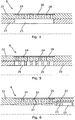
Fig. 4 shows a cross-sectional view of theinflow device 8 along an axial extension of theinflow device 8 being concentric with the axial extension of the casing. In this embodiment, theinflow device 8 comprises anouter sleeve 22 and aninner sleeve 23, and theinner sleeve 23 may be movable in relation to theouter sleeve 22. The cross-sectional view is taken along a row ofinflow openings 24 arranged in the extension of theinflow device 8. In this row, there are seveninflow openings 24. The inflow area of the inflow device is inter alia constituted by theseinflow openings 24 each having an opening area. If theinflow device 8 has several rows of inflow openings, the total opening area of all these rows provides the total available inflow area of the inflow device. Theinflow openings 24 are in fluid connection with theinner opening 25 of the secondinner sleeve 23 so that fluid from the reservoir may flow in through theinflow device 8. In this embodiment, theinner opening 25 is shown as a through-going groove extending in the axial extension of theinflow device 8. Theinner opening 25 has a larger extension than theinflow openings 24 to ensure that theinner opening 25, when being aligned with the inflow openings, does not prevent the fluid from flowing. Ascreen 26 or filter is arranged on the outside of the inflow openings. - Another embodiment of the
inflow device 8 is shown inFig. 5 in a cross-sectional view along an axial extension of theinflow device 8. Theinflow device 8 also comprises theouter sleeve 22 and theinner sleeve 23 which are movable in relation to each other. Theinflow openings 24 are in fluid connection with theinner openings 25 of the secondinner sleeve 23 to allow fluid from the reservoir to flow in through theinflow device 8. In this embodiment, theinner openings 25 are shown as seven through-going holes being aligned with theinflow openings 24 of the outer sleeve. Theinner openings 25 have a larger extension than each of theinflow openings 24 so they do not prevent the fluid from flowing. Again, ascreen 26 or filter is arranged on the outside of theinflow openings 24. - An additional embodiment of the
inflow device 8 is shown inFig. 6 in a cross-sectional view along a row ofinflow openings 24 arranged in the extension of theinflow device 8. Theinflow openings 24 terminate in anaxially extending channel 27 arranged in the wall of theouter sleeve 22. Theaxial channel 27 abuts anaxial channel 55 arranged in theinner sleeve 23, whereby theinflow openings 24 are in fluid communication with theinner opening 25 via the twoaxial channels screen 26 or filter is arranged on the outside of theinflow openings 24. The embodiment of theinflow device 8 shown inFig. 6 will be described further in connection withFig. 9 below. - The
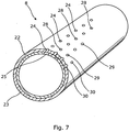
inflow device 8 ofFig. 4 is shown in perspective inFig. 7 . Theinflow device 8 comprises theouter sleeve 22 and theinner sleeve 23, wherein theinner sleeve 23 is movable in relation to theouter sleeve 22 by rotation. Four rows ofinflow openings inflow device 8. The first row has seveninflow openings 24, as shown in the cross-sectional view inFig. 4 . The second row has sixinflow openings 28. The third row has fourinflow openings 29, and the fourth row has twoinflow openings 30. Theinflow openings inflow device 8. - In other embodiments, the inflow device may have a different number of rows and a different number of inflow openings in each row. Thus, the embodiment shown in
Fig. 7 is one configuration of theinflow device 8. - The
inner sleeve 23 is shown inFig. 7 with fourinner openings 25 visible in cross-section, and theopenings 25 are each aligned with an inflow opening in the row ofinflow openings 24 arranged in theouter sleeve 22. Also, theinflow device 8 may have a different number of inner openings and different positions along the periphery of the inner sleeve. -
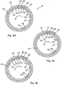
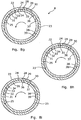
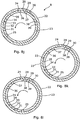
Figs. 8a to 8o show a sequence of different adjustments to different positions of the inflow device in relation to the desired inflow volume rate of theinflow device 8. - In the same manner as described above, the
inflow device 8 comprises aninner sleeve 23 or tubular which is rotatable within theouter sleeve 22 or tubular. Theinflow device 8 is shown in a cross-sectional view of a radial extension of theinflow device 8. Theouter sleeve 22 has four rows ofinflow openings first row 24, there are seven inflow openings, as shown inFig. 7 , in thesecond row 28, there are six openings, in thethird row 29, there are four openings, and in the fourth row, there are two openings. InFig. 8a , theinner sleeve 23 has teninner openings Fig. 4 , and the openings are arranged along the periphery of theinner sleeve 23. Theinner openings outer inflow openings 24 can optionally be opened or closed by rotating theinner sleeve 23, which will be further described below. - In
Fig. 8a , the rows ofinflow openings inner openings inner sleeve 23. Thus, inFig. 8a , allinflow openings inflow device 8 are open, whereby fluid may flow through all nineteen openings. This is the maximum flow capacity of theinflow device 8. - In
Fig. 8b , theinner sleeve 23 is rotated slightly to the right, whereby theinner opening 25 is aligned with the first row ofinflow openings 24, theinner opening 31 is aligned with the row ofinflow openings 29, and theinner opening 32 is aligned with the row ofinflow openings 30. Thus, by this adjustment of theinflow device 8, the rows ofinflow openings inflow openings 28 is closed, resulting in thirteen openings being open. By rotating the inner sleeve even further so that theinner opening 25 is aligned with the third row ofinflow openings 29, four openings are open, and by rotating the inner sleeve even further so that theinner opening 25 is aligned with the fourth row ofinflow openings 30, two openings are open. - In
Fig. 8c , theinner sleeve 23 is rotated slightly to the left, whereby theinner opening 31 is aligned with the row ofinflow openings 28, theinner opening 32 is aligned with the row ofinflow openings 29, and theinner opening 33 is aligned with the row ofinflow openings 30. Thus, by this adjustment of theinflow device 8, the rows ofinflow openings inflow openings 24 is closed, resulting in twelve openings being open. - In
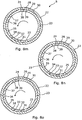
Fig. 8d , theinner sleeve 23 is rotated slightly to the left in relation to the adjustment ofFig. 8c , whereby theinner opening 32 is aligned with the row ofinflow openings 24, theinner opening 33 is aligned with the row ofinflow openings 28, and theinner opening 34 is aligned with the row ofinflow openings 29. Thus, by this adjustment of theinflow device 8, the rows ofinflow openings inflow openings 30 is closed, resulting in seventeen openings being open. - In
Fig. 8e , theinner sleeve 23 is rotated slightly to the left in relation to the adjustment ofFig. 8d , whereby theinner opening 33 is aligned with the row ofinflow openings 24, theinner opening 34 is aligned with the row ofinflow openings 28, and theinner opening 35 is aligned with the row ofinflow openings 30. Thus, by this adjustment of theinflow device 8, the rows ofinflow openings inflow openings 29 is closed, resulting in fifteen openings being open. - In
Fig. 8f , theinner sleeve 23 is rotated slightly to the left in relation to the adjustment ofFig. 8e , whereby theinner opening 34 is aligned with the row ofinflow openings 24 and theinner opening 35 is aligned with the row ofinflow openings 29. Thus, by this adjustment of theinflow device 8, the rows ofinflow openings inflow openings - In
Fig. 8g , theinner sleeve 23 is rotated slightly to the left in relation to the adjustment ofFig. 8f , whereby theinner opening 35 is aligned with the row ofinflow openings 28. Thus, by this adjustment of theinflow device 8, the row ofinflow openings 28 are open and the rows ofinflow openings - In
Fig. 8h , theinner sleeve 23 is rotated slightly to the left in relation to the adjustment ofFig. 8g , whereby theinner opening 35 is aligned with the row ofinflow openings 24 and theinner opening 36 is aligned with the row ofinflow openings 30. Thus, by this adjustment of theinflow device 8, the rows ofinflow openings inflow openings - In
Fig. 8i , theinner sleeve 23 is rotated slightly to the left in relation to the adjustment ofFig. 8h , whereby theinner opening 36 is aligned with the row ofinflow openings 28 and theinner opening 37 is aligned with the row ofinflow openings 30. Thus, by this adjustment of theinflow device 8, the rows ofinflow openings inflow openings - In
Fig. 8j , theinner sleeve 23 is rotated slightly to the left in relation to the adjustment ofFig. 8i , whereby theinner opening 36 is aligned with the row ofinflow openings 24 and theinner opening 37 is aligned with the row ofinflow openings 29. Thus, by this adjustment of theinflow device 8, the rows ofinflow openings inflow openings Fig. 8f . - In
Fig. 8k , theinner sleeve 23 is rotated slightly to the left in relation to the adjustment ofFig. 8j , whereby theinner opening 38 is aligned with the row ofinflow openings 29 and theinner opening 39 is aligned with the row ofinflow openings 30. Thus, by this adjustment of theinflow device 8, the rows ofinflow openings inflow openings - In
Fig. 8l , theinner sleeve 23 is rotated slightly to the left in relation to the adjustment ofFig. 8k , whereby theinner opening 38 is aligned with the row ofinflow openings 28 and theinner opening 39 is aligned with the row ofinflow openings 29. Thus, by this adjustment of theinflow device 8, the rows ofinflow openings inflow openings - In
Fig. 8m , theinner sleeve 23 is rotated slightly to the left in relation to the adjustment ofFig. 8l , whereby theinner opening 38 is aligned with the row ofinflow openings 24 and theinner opening 39 is aligned with the row ofinflow openings 28. Thus, in this adjustment of theinflow device 8, the rows ofinflow openings inflow openings - In
Fig. 8n , theinner sleeve 23 is rotated slightly to the left in relation to the adjustment ofFig. 8m , whereby theinner opening 39 is aligned with the row ofinflow openings 24. Thus, by this adjustment of theinflow device 8, the rows ofinflow openings 24 are open and the rows ofinflow openings - In
Fig. 8o , theinner sleeve 23 is rotated slightly to the left in relation to the adjustment ofFig. 8n , whereby all rows ofinflow openings inflow device 8 is closed. - The sequence of adjustments shown in
Figs. 8a-8o shows different flow capacities of theinflow device 8, resulting in fourteen different volume rates. Even though some possible adjustments of theinflow device 8 are not shown inFigs. 8a-8o , it is evident for the skilled person that the configuration of theinflow device 8 makes it possible to open and close all rows of inflow openings independently of each other by rotating the inner sleeve into the intended position. -
Fig. 9 shows a longitudinal cross-sectional view of another embodiment of aninflow device 8. Theinflow device 8 comprises a first sleeve or tubular 40 having twelveinflow openings 24 in afirst wall 41 and twelve firstaxial channels 27 extending in thefirst wall 41 from theinflow openings 24 to anoutlet 53. By axial channels is meant that the channels extend in an axial direction in relation to theinflow device 8. - The inflow device also comprises a
second sleeve 42 or tubular having afirst end 43 near theoutlet 53 and asecond end 44 and, in this view, sixinner openings 25. Even though thesecond sleeve 42 or tubular only shows sixinner openings 25, the number of inner openings is actually the same as in thefirst sleeve 40 or tubular, i.e. 12 inner openings. - Furthermore, the
second sleeve 42 or tubular is rotatable within thefirst sleeve 40 or tubular, and thesecond sleeve 42 has asecond wall 45 having twelve second axial channels (not shown) extending in thesecond wall 45 from thefirst end 43 to theinner opening 25. Thus, eachinner opening 25 has its own second axial channel. - The
second sleeve 42 or tubular is arranged in an innercircumferential recess 46 in thefirst wall 41 of thefirst sleeve 40 or tubular, meaning that when thesecond sleeve 42 or tubular is arranged in the recess, thesecond sleeve 42 or tubular will not decrease the overall inner diameter of the inflow device and thereby of the production casing. - The
second sleeve 42 or tubular is rotatable in relation to thefirst sleeve 40 or tubular at least between a first position, in which thefirst channel 27 and second channel (not shown) are aligned to allow fluid to flow from the reservoir into the production casing via thefirst end 43 of thesecond sleeve 42 or tubular, and a second position (the position shown inFig. 9 ), in which thefirst channel 27 and second channel (not shown) are not aligned, meaning that fluid is prevented from flowing into the production casing. - The
inflow device 8 also comprises afirst packer 47 which is arranged between thefirst sleeve 40 or tubular and thefirst end 43 of thesecond sleeve 42 or tubular. Thepacker 47 extends around the innercircumferential recess 46 and has an inner diameter which is substantially the same as that of the second sleeve or tubular. Thepacker 47 has a number of through-goingpacker channels 48 corresponding to the number of first axial channels, i.e. in this embodiment twelve, thepacker channels 48 being aligned with the firstaxial channels 27. The packer is fixedly connected with the first sleeve or tubular so that thepacker channels 48 are fluidly connected with first axial channels. The packer is ringshaped, and the through-goingpacker channels 48 extend through the packer along the axial extension of the first sleeve or tubular. - The
packer 47 is preferably made of ceramics, whereby it is possible to make the contact surfaces of thepacker 47 smooth, which enhances the sealing properties of thepacker 47, since the smooth contact surface may be pressed closer to the opposite surface which is thefirst end 43 of thesecond sleeve 42 or tubular. However, in other embodiments, the packer may be made of metal, composites, polymers or the like. - Furthermore, a
second packer 49 is arranged between thefirst sleeve 40 or tubular and thesecond end 44 of thesecond sleeve 42 or tubular. However, in another embodiment, the second packer is omitted, whereby thesecond end 44 of thesecond sleeve 42 or tubular faces the first wall of thefirst sleeve 40 or tubular. - In
Fig. 9 , afirst spring element 50 is arranged between thefirst packer 47 and thefirst sleeve 40 or tubular. Thespring element 50 thus forces the first packer against thesecond sleeve 42 to provide a seal therebetween. - Furthermore, the
second sleeve 42 or tubular may comprise at least onerecess 51 accessible from within, therecess 51 being adapted to receive a key tool (not shown) for rotating thesecond sleeve 42 or tubular in relation to thefirst sleeve 40 or tubular. - The adjustment of the
inflow devices inflow devices - The
inflow device 8 ofFig. 7 has aninner sleeve 23 rotating in relation to anouter sleeve 22, and inFig. 10 , theinner sleeve 23 slides axially in relation to theouter sleeve 22. Theinner sleeve 23 slides in a recess in theouter sleeve 22, as shown inFig. 11 where the inner sleeve covers three of the four rows shown in -
Fig. 10 , and thus, all theinflow openings 24 except two are covered. The first row comprises eightinflow openings 24, the second row comprises sixinflow openings 24, the third row comprises fourinflow openings 24, and the fourth row comprises twoinflow openings 24. By sliding the sleeve back and forth in the recess along the inner surface of the outer sleeve, the number ofinflow openings 24 which the fluid may flow through may be varied in the same manner as in the embodiment of theinflow device 8 shown inFig. 7 . In other embodiments of an inflow device having an axially slidable inner sleeve, the inflow device may have a different number of rows and a different number of inflow openings in each row. Thus, the embodiment shown inFigs. 9 and10 is only one configuration of theinflow device 8. -
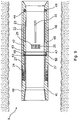
Fig. 1 shows the production casing comprising annular barriers, each annular barrier being adapted for expansion in anannulus 52 between a production casing and aninside wall 54 of a borehole 55 downhole. Each annular barrier comprises atubular part 57 for mounting as part of the production casing and anexpandable sleeve 58 surrounding the tubular part. Each end 59, 60 of the expandable sleeve is fastened to the tubular part by means of aconnection part 72. At least one end is slidably connected with the tubular part. The expandable sleeve surrounds the tubular part and defines anannular barrier space 73 between the tubular part and the expandable sleeve. The annular barrier further comprises anaperture 71 in the tubular part for letting fluid into the annular barrier space to expand the sleeve. The annular barriers are arranged separating thefirst reservoir zone 6 and thesecond reservoir zone 7 so that three annular barriers provide two reservoir zones. The expandable sleeve, the tubular part and the connection parts are made of metal. - In other embodiments, the inflow devices may be remotely adjustable, e.g. by wireline or wireless control.
- The
inflow device 8 is adapted to be inserted and form part of theproduction casing 3, thus forming a cased completion (not shown). Accordingly, the ends of theinflow device 8 are adapted to be connected with another casing element by conventional connection means, for instance by means of a threaded connection. - In the embodiments described above, the outer openings are shown as openings per se. However, the outer openings may comprise flow restrictors, throttles or valves, such as inflow control valves (not shown).
- Even though the above-mentioned embodiments have been described primarily in relation to rotatable movement of the inner sleeve in relation to the outer sleeve, the inner sleeve may be slidably movable in relation to the outer sleeve.
- By fluid or well fluid is meant any kind of fluid that may be present in oil or gas wells downhole, such as natural gas, oil, oil mud, crude oil, water, etc. By gas is meant any kind of gas composition present in a well, completion, or open hole, and by oil is meant any kind of oil composition, such as crude oil, an oil-containing fluid, etc. Gas, oil, and water fluids may thus all comprise other elements or substances than gas, oil, and/or water, respectively.
- By a casing is meant any kind of pipe, tubing, tubular, liner, string etc. used downhole in relation to oil or natural gas production.
- In the event that the tools are not submergible all the way into the casing, a downhole tractor can be used to push the tools all the way into position in the well. A downhole tractor is any kind of driving tool capable of pushing or pulling tools in a well downhole, such as a Well Tractor®.
- Although the invention has been described in the above in connection with preferred embodiments of the invention, it will be evident for a person skilled in the art that several modifications are conceivable without departing from the invention as defined by the following claims.
Claims (15)
- A production system (1) for producing hydrocarbons from a well (2), comprising:- a production casing (3),- a first reservoir zone (6) comprising at least a first fluid (10), extending along and outside a part of the production casing (3),- a second reservoir zone (7) comprising at least a second fluid (11), extending along and outside another part of the production casing (3),- a first inflow device (8) arranged in the first reservoir zone (6), having a first inflow area and being adapted to let the first fluid (10) into the production casing (3) at a first volume rate (V1), and- a second inflow device (9) arranged in the second reservoir zone (7), having a second inflow area and being adapted to let the second fluid (11) into the production casing (3) at a second volume rate (V2),wherein the first and second inflow areas of the inflow devices (8, 9) are adjustable, whereby the first and second inflow devices (8, 9) can be adjusted so that the first volume rate (V1) is equal to or higher than the second volume rate (V2), and wherein the inflow device (8, 9) comprises a first outer sleeve (22) and a second inner sleeve (23) movable in relation to each other, characterised in that the first outer sleeve (22) has outer inflow openings (24, 28, 29, 30) arranged in rows with a different number of openings in each row, and in that the second inner sleeve (23) has inner openings (25, 31, 32, 33, 34, 35, 36, 37, 38, 39), whereby the inflow area of the inflow device (8, 9) is adjustable in that the inner openings (25, 31, 32, 33, 34, 35, 36, 37, 38, 39) of the second inner sleeve (23) can be moved and aligned in relation to the outer openings (24, 28, 29, 30) of the first sleeve (22).
- A production system (1) according to claim 1, wherein the inner openings are arranged with a distance between them which is different from a distance between the outer openings (24, 28, 29, 30), whereby the inflow area of the inflow device (8, 9) is adjustable in that the inner openings (25, 31, 32, 33, 34, 35, 36, 37, 38, 39) of the second inner sleeve (23) can be moved and aligned in relation to the outer openings (24, 28, 29, 30) of the first sleeve (22).
- A production system (1) according to claim 1 or 2, wherein the inner openings of the inner sleeve may be arranged with predetermined circumferenctial distances between them so that each row of outer inflow openings can optionally be opened or closed by moving the inner sleeve.
- A production system (1) according to any of the preceding claims, further comprising a monitoring unit (4) adapted to measure a production outcome of the well (2).
- A production system (1) according to claim 4, wherein the monitoring unit (4) is adapted to measure a water content of the production outcome so that the inflow devices (8, 9) may be adjusted to obtain an optimum between production outcome and water content.
- A production system (1) according to claim 4 or 5, wherein the monitoring unit (4) is adapted to measure a volume rate of the production outcome and/or a pressure at the top of the well (2) so that the inflow devices (8, 9) may be adjusted based on of the volume rate and/or pressure measured at the top of the well (2).
- A production system (1) according to any of the preceding claims, wherein the reservoir zones (6, 7) are separated by annular barriers (12).
- A production system (1) according to any of the preceding claims, wherein the first fluid (10) is oil and the second fluid (11) is water or gas.
- A production system (1) according to any of the preceding claims, wherein the inflow device comprises a first packer (47), the second sleeve is arranged in a recess (46) of the first sleeve, and the first packer is arranged between the first sleeve and the second sleeve.
- A production system (1) according to claim 9, wherein the packer extends around the inner circumferential recess (46) and has an inner diameter which is substantially the same as that of the second sleeve.
- A production system (1) according to any of the preceding claims, wherein the production casing comprises annular barriers, each annular barrier being adapted for being expanded in an annulus (52) between the production casing and an inside wall (54) of a borehole (55) downhole, and each annular barrier comprising:- a tubular part (57) for mounting as part of the production casing,- an expandable sleeve (58) surrounding the tubular part, each end (59, 60) of the expandable sleeve being fastened to the tubular part by means of a connection part (72),- an annular barrier space (73) between the tubular part and the expandable sleeve, and- an aperture (71) in the tubular part for letting fluid into the annular barrier space to expand the sleeve,wherein annular barriers are arranged, separating the first reservoir zone (6) and the second reservoir zone (7).
- A well completion comprising the production system (1) according to any of claims 1 to 11 and a well head (5).
- A production method for production of hydrocarbons from a well (2) by means of the production system according to any of claims 1-11, comprising the steps of:- identifying a first reservoir zone (6) comprising at least a first fluid (10),- identifying a second reservoir zone (7) comprising at least a second fluid (11),- opening a first inflow device (8) in the first zone (6) to let the at least first fluid (10) into a production casing (3) at a first volume rate (V1),- opening a second inflow device (9) in the second zone (7) to let the at least second fluid (11) into the production casing (3) at a second volume rate (V2),- monitoring a production outcome of the well (2), and- adjusting the first and second inflow devices (8, 9) based on the production outcome so that the first volume rate (V1) is equal to or higher than the second volume rate (V2) or so that the second volume rate is higher than the first volume rate.
- A method according to claim 13, wherein the monitoring step comprises one or more of the steps of:- measuring a pressure at the top of the well,- measuring a volume rate of the production outcome at the top of the well, and/or- measuring a water content of the production outcome at the top of the well.
- A method according to claim 13 or 14, wherein the step of adjusting the first and second inflow devices further comprises adjustment of at least one of the inflow devices (8, 9) based on the measured pressure, volume rate and/or water content at the top of the well.
Priority Applications (1)
| Application Number | Priority Date | Filing Date | Title |
|---|---|---|---|
| EP12806485.4A EP2795052B1 (en) | 2011-12-23 | 2012-12-21 | Production system for producing hydrocarbons from a well |
Applications Claiming Priority (3)
| Application Number | Priority Date | Filing Date | Title |
|---|---|---|---|
| EP11195580.3A EP2607616A1 (en) | 2011-12-23 | 2011-12-23 | Production system for producing hydrocarbons from a well |
| EP12806485.4A EP2795052B1 (en) | 2011-12-23 | 2012-12-21 | Production system for producing hydrocarbons from a well |
| PCT/EP2012/076541 WO2013092945A1 (en) | 2011-12-23 | 2012-12-21 | Production system for producing hydrocarbons from a well |
Publications (2)
| Publication Number | Publication Date |
|---|---|
| EP2795052A1 EP2795052A1 (en) | 2014-10-29 |
| EP2795052B1 true EP2795052B1 (en) | 2016-07-20 |
Family
ID=47435990
Family Applications (2)
| Application Number | Title | Priority Date | Filing Date |
|---|---|---|---|
| EP11195580.3A Withdrawn EP2607616A1 (en) | 2011-12-23 | 2011-12-23 | Production system for producing hydrocarbons from a well |
| EP12806485.4A Not-in-force EP2795052B1 (en) | 2011-12-23 | 2012-12-21 | Production system for producing hydrocarbons from a well |
Family Applications Before (1)
| Application Number | Title | Priority Date | Filing Date |
|---|---|---|---|
| EP11195580.3A Withdrawn EP2607616A1 (en) | 2011-12-23 | 2011-12-23 | Production system for producing hydrocarbons from a well |
Country Status (10)
| Country | Link |
|---|---|
| US (1) | US20140352956A1 (en) |
| EP (2) | EP2607616A1 (en) |
| CN (1) | CN104254664A (en) |
| AU (1) | AU2012356949B2 (en) |
| BR (1) | BR112014013982A2 (en) |
| CA (1) | CA2858643A1 (en) |
| DK (1) | DK2795052T3 (en) |
| MX (1) | MX342054B (en) |
| RU (1) | RU2014127616A (en) |
| WO (1) | WO2013092945A1 (en) |
Families Citing this family (10)
| Publication number | Priority date | Publication date | Assignee | Title |
|---|---|---|---|---|
| AU2011301169B2 (en) | 2010-09-09 | 2016-11-10 | National Oilwell Varco, L.P. | Downhole rotary drilling apparatus with formation-interfacing members and control system |
| US8869916B2 (en) | 2010-09-09 | 2014-10-28 | National Oilwell Varco, L.P. | Rotary steerable push-the-bit drilling apparatus with self-cleaning fluid filter |
| US9816348B2 (en) * | 2015-03-24 | 2017-11-14 | Halliburton Energy Services, Inc. | Downhole flow control assemblies and methods of use |
| JP6618813B2 (en) * | 2016-01-21 | 2019-12-11 | 株式会社大阪防水建設社 | Groundwater sampling method |
| US10619474B2 (en) | 2017-11-14 | 2020-04-14 | Saudi Arabian Oil Company | Remotely operated inflow control valve |
| RU179815U1 (en) * | 2018-01-10 | 2018-05-24 | Владимир Александрович Чигряй | FLUID FLOW CONTROL DEVICE |
| RU178922U1 (en) * | 2018-01-10 | 2018-04-23 | Владимир Александрович Чигряй | FLUID FLOW CONTROL DEVICE |
| DE102020117596A1 (en) | 2020-07-03 | 2022-01-05 | Fraunhofer-Gesellschaft zur Förderung der angewandten Forschung eingetragener Verein | Sieve filters for geotechnical systems |
| US11788380B2 (en) * | 2021-10-20 | 2023-10-17 | Saudi Arabian Oil Company | Installation of sliding sleeve with shifting profile in passive inflow control devices |
| CN114645543B (en) * | 2022-04-27 | 2023-01-24 | 中国矿业大学 | Fixed-point grouting method and fixed-point grouting device for pile hole in karst area |
Family Cites Families (14)
| Publication number | Priority date | Publication date | Assignee | Title |
|---|---|---|---|---|
| US3993130A (en) * | 1975-05-14 | 1976-11-23 | Texaco Inc. | Method and apparatus for controlling the injection profile of a borehole |
| US4691778A (en) * | 1987-02-09 | 1987-09-08 | Pyne R David G | Downhole water flow controller for aquifer storage recovery wells |
| US4858691A (en) * | 1988-06-13 | 1989-08-22 | Baker Hughes Incorporated | Gravel packing apparatus and method |
| GB9025230D0 (en) * | 1990-11-20 | 1991-01-02 | Framo Dev Ltd | Well completion system |
| US5664628A (en) * | 1993-05-25 | 1997-09-09 | Pall Corporation | Filter for subterranean wells |
| US5624560A (en) * | 1995-04-07 | 1997-04-29 | Baker Hughes Incorporated | Wire mesh filter including a protective jacket |
| US5642781A (en) * | 1994-10-07 | 1997-07-01 | Baker Hughes Incorporated | Multi-passage sand control screen |
| US6873267B1 (en) * | 1999-09-29 | 2005-03-29 | Weatherford/Lamb, Inc. | Methods and apparatus for monitoring and controlling oil and gas production wells from a remote location |
| US6644406B1 (en) * | 2000-07-31 | 2003-11-11 | Mobil Oil Corporation | Fracturing different levels within a completion interval of a well |
| US6978840B2 (en) * | 2003-02-05 | 2005-12-27 | Halliburton Energy Services, Inc. | Well screen assembly and system with controllable variable flow area and method of using same for oil well fluid production |
| US7448591B2 (en) * | 2006-07-03 | 2008-11-11 | Bj Services Company | Step ratchet mechanism |
| US7832473B2 (en) * | 2007-01-15 | 2010-11-16 | Schlumberger Technology Corporation | Method for controlling the flow of fluid between a downhole formation and a base pipe |
| US8210258B2 (en) * | 2009-12-22 | 2012-07-03 | Baker Hughes Incorporated | Wireline-adjustable downhole flow control devices and methods for using same |
| GB2495504B (en) * | 2011-10-11 | 2018-05-23 | Halliburton Mfg & Services Limited | Downhole valve assembly |
-
2011
- 2011-12-23 EP EP11195580.3A patent/EP2607616A1/en not_active Withdrawn
-
2012
- 2012-12-21 BR BR112014013982A patent/BR112014013982A2/en not_active IP Right Cessation
- 2012-12-21 CN CN201280060532.3A patent/CN104254664A/en active Pending
- 2012-12-21 WO PCT/EP2012/076541 patent/WO2013092945A1/en active Application Filing
- 2012-12-21 CA CA2858643A patent/CA2858643A1/en not_active Abandoned
- 2012-12-21 US US14/363,880 patent/US20140352956A1/en not_active Abandoned
- 2012-12-21 AU AU2012356949A patent/AU2012356949B2/en not_active Ceased
- 2012-12-21 MX MX2014006957A patent/MX342054B/en active IP Right Grant
- 2012-12-21 RU RU2014127616A patent/RU2014127616A/en not_active Application Discontinuation
- 2012-12-21 DK DK12806485.4T patent/DK2795052T3/en active
- 2012-12-21 EP EP12806485.4A patent/EP2795052B1/en not_active Not-in-force
Also Published As
| Publication number | Publication date |
|---|---|
| MX342054B (en) | 2016-09-12 |
| EP2607616A1 (en) | 2013-06-26 |
| CA2858643A1 (en) | 2013-06-27 |
| DK2795052T3 (en) | 2016-11-14 |
| CN104254664A (en) | 2014-12-31 |
| BR112014013982A2 (en) | 2017-06-13 |
| MX2014006957A (en) | 2014-09-01 |
| WO2013092945A1 (en) | 2013-06-27 |
| US20140352956A1 (en) | 2014-12-04 |
| AU2012356949B2 (en) | 2015-09-03 |
| RU2014127616A (en) | 2016-02-10 |
| AU2012356949A1 (en) | 2014-07-24 |
| EP2795052A1 (en) | 2014-10-29 |
Similar Documents
| Publication | Publication Date | Title |
|---|---|---|
| EP2795052B1 (en) | Production system for producing hydrocarbons from a well | |
| CA2501839C (en) | Hydraulic stepping valve actuated sliding sleeve | |
| US8931557B2 (en) | Wellbore servicing assemblies and methods of using the same | |
| US20050034875A1 (en) | Valves for Use in Wells | |
| US20060201677A1 (en) | Multilateral production apparatus and method | |
| US8668018B2 (en) | Selective dart system for actuating downhole tools and methods of using same | |
| US10443347B2 (en) | Downhole completion tool | |
| AU2011384179A1 (en) | Unequal load collet and method of use | |
| WO2013101715A2 (en) | Downhole tool with pumpable section | |
| US9650864B2 (en) | Remotely operated production valve and method | |
| US20180266218A1 (en) | Annular flow rings for sand control screen assemblies | |
| US9163493B2 (en) | Wellbore servicing assemblies and methods of using the same | |
| EP2815067B1 (en) | Fluid bypass for inflow control device tube | |
| EP2245258B1 (en) | Improved tubing section | |
| US7992637B2 (en) | Reverse flow in-flow control device | |
| WO2014200469A1 (en) | High-temperature, high-pressure, fluid-tight seal using a series of annular rings | |
| RU2728626C1 (en) | Device with cross flow assembly for flow control inside well | |
| US20130255962A1 (en) | Downhole Circulating Valve Having a Metal-To-Metal Seal and Method for Operating Same | |
| CA2613115C (en) | System for controlling the flow of well fluid | |
| WO2014004561A2 (en) | Method and apparatus for injecting gas into a reservoir | |
| US8763707B2 (en) | Downhole circulating valve having a metal-to-metal seal | |
| WO2013151534A1 (en) | Downhole circulating valve having a metal-to-metal seal and method for operating same |
Legal Events
| Date | Code | Title | Description |
|---|---|---|---|
| PUAI | Public reference made under article 153(3) epc to a published international application that has entered the european phase |
Free format text: ORIGINAL CODE: 0009012 |
|
| 17P | Request for examination filed |
Effective date: 20140702 |
|
| AK | Designated contracting states |
Kind code of ref document: A1 Designated state(s): AL AT BE BG CH CY CZ DE DK EE ES FI FR GB GR HR HU IE IS IT LI LT LU LV MC MK MT NL NO PL PT RO RS SE SI SK SM TR |
|
| DAX | Request for extension of the european patent (deleted) | ||
| GRAP | Despatch of communication of intention to grant a patent |
Free format text: ORIGINAL CODE: EPIDOSNIGR1 |
|
| INTG | Intention to grant announced |
Effective date: 20151012 |
|
| GRAS | Grant fee paid |
Free format text: ORIGINAL CODE: EPIDOSNIGR3 |
|
| INTG | Intention to grant announced |
Effective date: 20160216 |
|
| GRAA | (expected) grant |
Free format text: ORIGINAL CODE: 0009210 |
|
| AK | Designated contracting states |
Kind code of ref document: B1 Designated state(s): AL AT BE BG CH CY CZ DE DK EE ES FI FR GB GR HR HU IE IS IT LI LT LU LV MC MK MT NL NO PL PT RO RS SE SI SK SM TR |
|
| REG | Reference to a national code |
Ref country code: GB Ref legal event code: FG4D |
|
| REG | Reference to a national code |
Ref country code: CH Ref legal event code: EP |
|
| REG | Reference to a national code |
Ref country code: IE Ref legal event code: FG4D |
|
| REG | Reference to a national code |
Ref country code: AT Ref legal event code: REF Ref document number: 814264 Country of ref document: AT Kind code of ref document: T Effective date: 20160815 |
|
| REG | Reference to a national code |
Ref country code: DE Ref legal event code: R096 Ref document number: 602012020814 Country of ref document: DE |
|
| REG | Reference to a national code |
Ref country code: NL Ref legal event code: FP |
|
| REG | Reference to a national code |
Ref country code: LT Ref legal event code: MG4D |
|
| REG | Reference to a national code |
Ref country code: NO Ref legal event code: T2 Effective date: 20160720 Ref country code: DK Ref legal event code: T3 Effective date: 20161110 |
|
| REG | Reference to a national code |
Ref country code: FR Ref legal event code: PLFP Year of fee payment: 5 |
|
| REG | Reference to a national code |
Ref country code: AT Ref legal event code: MK05 Ref document number: 814264 Country of ref document: AT Kind code of ref document: T Effective date: 20160720 |
|
| PG25 | Lapsed in a contracting state [announced via postgrant information from national office to epo] |
Ref country code: FI Free format text: LAPSE BECAUSE OF FAILURE TO SUBMIT A TRANSLATION OF THE DESCRIPTION OR TO PAY THE FEE WITHIN THE PRESCRIBED TIME-LIMIT Effective date: 20160720 Ref country code: HR Free format text: LAPSE BECAUSE OF FAILURE TO SUBMIT A TRANSLATION OF THE DESCRIPTION OR TO PAY THE FEE WITHIN THE PRESCRIBED TIME-LIMIT Effective date: 20160720 Ref country code: RS Free format text: LAPSE BECAUSE OF FAILURE TO SUBMIT A TRANSLATION OF THE DESCRIPTION OR TO PAY THE FEE WITHIN THE PRESCRIBED TIME-LIMIT Effective date: 20160720 Ref country code: IT Free format text: LAPSE BECAUSE OF FAILURE TO SUBMIT A TRANSLATION OF THE DESCRIPTION OR TO PAY THE FEE WITHIN THE PRESCRIBED TIME-LIMIT Effective date: 20160720 Ref country code: IS Free format text: LAPSE BECAUSE OF FAILURE TO SUBMIT A TRANSLATION OF THE DESCRIPTION OR TO PAY THE FEE WITHIN THE PRESCRIBED TIME-LIMIT Effective date: 20161120 Ref country code: LT Free format text: LAPSE BECAUSE OF FAILURE TO SUBMIT A TRANSLATION OF THE DESCRIPTION OR TO PAY THE FEE WITHIN THE PRESCRIBED TIME-LIMIT Effective date: 20160720 |
|
| PGFP | Annual fee paid to national office [announced via postgrant information from national office to epo] |
Ref country code: NL Payment date: 20161215 Year of fee payment: 5 Ref country code: NO Payment date: 20161215 Year of fee payment: 5 Ref country code: GB Payment date: 20161220 Year of fee payment: 5 Ref country code: DK Payment date: 20161222 Year of fee payment: 5 |
|
| PG25 | Lapsed in a contracting state [announced via postgrant information from national office to epo] |
Ref country code: LV Free format text: LAPSE BECAUSE OF FAILURE TO SUBMIT A TRANSLATION OF THE DESCRIPTION OR TO PAY THE FEE WITHIN THE PRESCRIBED TIME-LIMIT Effective date: 20160720 Ref country code: SE Free format text: LAPSE BECAUSE OF FAILURE TO SUBMIT A TRANSLATION OF THE DESCRIPTION OR TO PAY THE FEE WITHIN THE PRESCRIBED TIME-LIMIT Effective date: 20160720 Ref country code: AT Free format text: LAPSE BECAUSE OF FAILURE TO SUBMIT A TRANSLATION OF THE DESCRIPTION OR TO PAY THE FEE WITHIN THE PRESCRIBED TIME-LIMIT Effective date: 20160720 Ref country code: PT Free format text: LAPSE BECAUSE OF FAILURE TO SUBMIT A TRANSLATION OF THE DESCRIPTION OR TO PAY THE FEE WITHIN THE PRESCRIBED TIME-LIMIT Effective date: 20161121 Ref country code: BE Free format text: LAPSE BECAUSE OF FAILURE TO SUBMIT A TRANSLATION OF THE DESCRIPTION OR TO PAY THE FEE WITHIN THE PRESCRIBED TIME-LIMIT Effective date: 20160720 Ref country code: PL Free format text: LAPSE BECAUSE OF FAILURE TO SUBMIT A TRANSLATION OF THE DESCRIPTION OR TO PAY THE FEE WITHIN THE PRESCRIBED TIME-LIMIT Effective date: 20160720 Ref country code: GR Free format text: LAPSE BECAUSE OF FAILURE TO SUBMIT A TRANSLATION OF THE DESCRIPTION OR TO PAY THE FEE WITHIN THE PRESCRIBED TIME-LIMIT Effective date: 20161021 Ref country code: ES Free format text: LAPSE BECAUSE OF FAILURE TO SUBMIT A TRANSLATION OF THE DESCRIPTION OR TO PAY THE FEE WITHIN THE PRESCRIBED TIME-LIMIT Effective date: 20160720 |
|
| PGFP | Annual fee paid to national office [announced via postgrant information from national office to epo] |
Ref country code: FR Payment date: 20161213 Year of fee payment: 5 |
|
| REG | Reference to a national code |
Ref country code: DE Ref legal event code: R097 Ref document number: 602012020814 Country of ref document: DE |
|
| PG25 | Lapsed in a contracting state [announced via postgrant information from national office to epo] |
Ref country code: RO Free format text: LAPSE BECAUSE OF FAILURE TO SUBMIT A TRANSLATION OF THE DESCRIPTION OR TO PAY THE FEE WITHIN THE PRESCRIBED TIME-LIMIT Effective date: 20160720 Ref country code: EE Free format text: LAPSE BECAUSE OF FAILURE TO SUBMIT A TRANSLATION OF THE DESCRIPTION OR TO PAY THE FEE WITHIN THE PRESCRIBED TIME-LIMIT Effective date: 20160720 |
|
| PGFP | Annual fee paid to national office [announced via postgrant information from national office to epo] |
Ref country code: DE Payment date: 20161222 Year of fee payment: 5 |
|
| PLBE | No opposition filed within time limit |
Free format text: ORIGINAL CODE: 0009261 |
|
| STAA | Information on the status of an ep patent application or granted ep patent |
Free format text: STATUS: NO OPPOSITION FILED WITHIN TIME LIMIT |
|
| PG25 | Lapsed in a contracting state [announced via postgrant information from national office to epo] |
Ref country code: BG Free format text: LAPSE BECAUSE OF FAILURE TO SUBMIT A TRANSLATION OF THE DESCRIPTION OR TO PAY THE FEE WITHIN THE PRESCRIBED TIME-LIMIT Effective date: 20161020 Ref country code: SK Free format text: LAPSE BECAUSE OF FAILURE TO SUBMIT A TRANSLATION OF THE DESCRIPTION OR TO PAY THE FEE WITHIN THE PRESCRIBED TIME-LIMIT Effective date: 20160720 Ref country code: CZ Free format text: LAPSE BECAUSE OF FAILURE TO SUBMIT A TRANSLATION OF THE DESCRIPTION OR TO PAY THE FEE WITHIN THE PRESCRIBED TIME-LIMIT Effective date: 20160720 Ref country code: SM Free format text: LAPSE BECAUSE OF FAILURE TO SUBMIT A TRANSLATION OF THE DESCRIPTION OR TO PAY THE FEE WITHIN THE PRESCRIBED TIME-LIMIT Effective date: 20160720 |
|
| 26N | No opposition filed |
Effective date: 20170421 |
|
| REG | Reference to a national code |
Ref country code: CH Ref legal event code: PL |
|
| PG25 | Lapsed in a contracting state [announced via postgrant information from national office to epo] |
Ref country code: SI Free format text: LAPSE BECAUSE OF FAILURE TO SUBMIT A TRANSLATION OF THE DESCRIPTION OR TO PAY THE FEE WITHIN THE PRESCRIBED TIME-LIMIT Effective date: 20160720 |
|
| PG25 | Lapsed in a contracting state [announced via postgrant information from national office to epo] |
Ref country code: MC Free format text: LAPSE BECAUSE OF FAILURE TO SUBMIT A TRANSLATION OF THE DESCRIPTION OR TO PAY THE FEE WITHIN THE PRESCRIBED TIME-LIMIT Effective date: 20160720 |
|
| REG | Reference to a national code |
Ref country code: IE Ref legal event code: MM4A |
|
| PG25 | Lapsed in a contracting state [announced via postgrant information from national office to epo] |
Ref country code: CH Free format text: LAPSE BECAUSE OF NON-PAYMENT OF DUE FEES Effective date: 20161231 Ref country code: LU Free format text: LAPSE BECAUSE OF NON-PAYMENT OF DUE FEES Effective date: 20161221 Ref country code: LI Free format text: LAPSE BECAUSE OF NON-PAYMENT OF DUE FEES Effective date: 20161231 |
|
| PG25 | Lapsed in a contracting state [announced via postgrant information from national office to epo] |
Ref country code: IE Free format text: LAPSE BECAUSE OF NON-PAYMENT OF DUE FEES Effective date: 20161221 |
|
| PG25 | Lapsed in a contracting state [announced via postgrant information from national office to epo] |
Ref country code: HU Free format text: LAPSE BECAUSE OF FAILURE TO SUBMIT A TRANSLATION OF THE DESCRIPTION OR TO PAY THE FEE WITHIN THE PRESCRIBED TIME-LIMIT; INVALID AB INITIO Effective date: 20121221 |
|
| PG25 | Lapsed in a contracting state [announced via postgrant information from national office to epo] |
Ref country code: MK Free format text: LAPSE BECAUSE OF FAILURE TO SUBMIT A TRANSLATION OF THE DESCRIPTION OR TO PAY THE FEE WITHIN THE PRESCRIBED TIME-LIMIT Effective date: 20160720 Ref country code: CY Free format text: LAPSE BECAUSE OF FAILURE TO SUBMIT A TRANSLATION OF THE DESCRIPTION OR TO PAY THE FEE WITHIN THE PRESCRIBED TIME-LIMIT Effective date: 20160720 |
|
| REG | Reference to a national code |
Ref country code: DE Ref legal event code: R119 Ref document number: 602012020814 Country of ref document: DE |
|
| REG | Reference to a national code |
Ref country code: NO Ref legal event code: MMEP |
|
| REG | Reference to a national code |
Ref country code: DK Ref legal event code: EBP Effective date: 20171231 |
|
| REG | Reference to a national code |
Ref country code: NL Ref legal event code: MM Effective date: 20180101 |
|
| GBPC | Gb: european patent ceased through non-payment of renewal fee |
Effective date: 20171221 |
|
| PG25 | Lapsed in a contracting state [announced via postgrant information from national office to epo] |
Ref country code: NL Free format text: LAPSE BECAUSE OF NON-PAYMENT OF DUE FEES Effective date: 20180101 Ref country code: MT Free format text: LAPSE BECAUSE OF NON-PAYMENT OF DUE FEES Effective date: 20161221 |
|
| REG | Reference to a national code |
Ref country code: FR Ref legal event code: ST Effective date: 20180831 |
|
| PG25 | Lapsed in a contracting state [announced via postgrant information from national office to epo] |
Ref country code: DE Free format text: LAPSE BECAUSE OF NON-PAYMENT OF DUE FEES Effective date: 20180703 Ref country code: FR Free format text: LAPSE BECAUSE OF NON-PAYMENT OF DUE FEES Effective date: 20180102 Ref country code: TR Free format text: LAPSE BECAUSE OF FAILURE TO SUBMIT A TRANSLATION OF THE DESCRIPTION OR TO PAY THE FEE WITHIN THE PRESCRIBED TIME-LIMIT Effective date: 20160720 Ref country code: AL Free format text: LAPSE BECAUSE OF FAILURE TO SUBMIT A TRANSLATION OF THE DESCRIPTION OR TO PAY THE FEE WITHIN THE PRESCRIBED TIME-LIMIT Effective date: 20160720 Ref country code: NO Free format text: LAPSE BECAUSE OF NON-PAYMENT OF DUE FEES Effective date: 20171231 |
|
| PG25 | Lapsed in a contracting state [announced via postgrant information from national office to epo] |
Ref country code: GB Free format text: LAPSE BECAUSE OF NON-PAYMENT OF DUE FEES Effective date: 20171221 |
|
| PG25 | Lapsed in a contracting state [announced via postgrant information from national office to epo] |
Ref country code: DK Free format text: LAPSE BECAUSE OF NON-PAYMENT OF DUE FEES Effective date: 20171231 |