EP2793484A1 - Electronic device - Google Patents
Electronic device Download PDFInfo
- Publication number
- EP2793484A1 EP2793484A1 EP13768542.6A EP13768542A EP2793484A1 EP 2793484 A1 EP2793484 A1 EP 2793484A1 EP 13768542 A EP13768542 A EP 13768542A EP 2793484 A1 EP2793484 A1 EP 2793484A1
- Authority
- EP
- European Patent Office
- Prior art keywords
- electronic device
- vibration plate
- area
- vibration
- piezoelectric element
- Prior art date
- Legal status (The legal status is an assumption and is not a legal conclusion. Google has not performed a legal analysis and makes no representation as to the accuracy of the status listed.)
- Granted
Links
Images



Classifications
-
- H—ELECTRICITY
- H04—ELECTRIC COMMUNICATION TECHNIQUE
- H04R—LOUDSPEAKERS, MICROPHONES, GRAMOPHONE PICK-UPS OR LIKE ACOUSTIC ELECTROMECHANICAL TRANSDUCERS; ELECTRIC HEARING AIDS; PUBLIC ADDRESS SYSTEMS
- H04R1/00—Details of transducers, loudspeakers or microphones
-
- H—ELECTRICITY
- H04—ELECTRIC COMMUNICATION TECHNIQUE
- H04R—LOUDSPEAKERS, MICROPHONES, GRAMOPHONE PICK-UPS OR LIKE ACOUSTIC ELECTROMECHANICAL TRANSDUCERS; ELECTRIC HEARING AIDS; PUBLIC ADDRESS SYSTEMS
- H04R17/00—Piezoelectric transducers; Electrostrictive transducers
-
- H—ELECTRICITY
- H04—ELECTRIC COMMUNICATION TECHNIQUE
- H04M—TELEPHONIC COMMUNICATION
- H04M1/00—Substation equipment, e.g. for use by subscribers
- H04M1/02—Constructional features of telephone sets
- H04M1/03—Constructional features of telephone transmitters or receivers, e.g. telephone hand-sets
- H04M1/035—Improving the acoustic characteristics by means of constructional features of the housing, e.g. ribs, walls, resonating chambers or cavities
-
- H—ELECTRICITY
- H04—ELECTRIC COMMUNICATION TECHNIQUE
- H04R—LOUDSPEAKERS, MICROPHONES, GRAMOPHONE PICK-UPS OR LIKE ACOUSTIC ELECTROMECHANICAL TRANSDUCERS; ELECTRIC HEARING AIDS; PUBLIC ADDRESS SYSTEMS
- H04R1/00—Details of transducers, loudspeakers or microphones
- H04R1/02—Casings; Cabinets ; Supports therefor; Mountings therein
-
- H—ELECTRICITY
- H04—ELECTRIC COMMUNICATION TECHNIQUE
- H04R—LOUDSPEAKERS, MICROPHONES, GRAMOPHONE PICK-UPS OR LIKE ACOUSTIC ELECTROMECHANICAL TRANSDUCERS; ELECTRIC HEARING AIDS; PUBLIC ADDRESS SYSTEMS
- H04R7/00—Diaphragms for electromechanical transducers; Cones
- H04R7/02—Diaphragms for electromechanical transducers; Cones characterised by the construction
- H04R7/04—Plane diaphragms
- H04R7/045—Plane diaphragms using the distributed mode principle, i.e. whereby the acoustic radiation is emanated from uniformly distributed free bending wave vibration induced in a stiff panel and not from pistonic motion
-
- H—ELECTRICITY
- H04—ELECTRIC COMMUNICATION TECHNIQUE
- H04R—LOUDSPEAKERS, MICROPHONES, GRAMOPHONE PICK-UPS OR LIKE ACOUSTIC ELECTROMECHANICAL TRANSDUCERS; ELECTRIC HEARING AIDS; PUBLIC ADDRESS SYSTEMS
- H04R7/00—Diaphragms for electromechanical transducers; Cones
- H04R7/02—Diaphragms for electromechanical transducers; Cones characterised by the construction
- H04R7/04—Plane diaphragms
- H04R7/06—Plane diaphragms comprising a plurality of sections or layers
-
- H—ELECTRICITY
- H04—ELECTRIC COMMUNICATION TECHNIQUE
- H04R—LOUDSPEAKERS, MICROPHONES, GRAMOPHONE PICK-UPS OR LIKE ACOUSTIC ELECTROMECHANICAL TRANSDUCERS; ELECTRIC HEARING AIDS; PUBLIC ADDRESS SYSTEMS
- H04R2400/00—Loudspeakers
- H04R2400/03—Transducers capable of generating both sound as well as tactile vibration, e.g. as used in cellular phones
-
- H—ELECTRICITY
- H04—ELECTRIC COMMUNICATION TECHNIQUE
- H04R—LOUDSPEAKERS, MICROPHONES, GRAMOPHONE PICK-UPS OR LIKE ACOUSTIC ELECTROMECHANICAL TRANSDUCERS; ELECTRIC HEARING AIDS; PUBLIC ADDRESS SYSTEMS
- H04R2440/00—Bending wave transducers covered by H04R, not provided for in its groups
- H04R2440/05—Aspects relating to the positioning and way or means of mounting of exciters to resonant bending wave panels
-
- H—ELECTRICITY
- H04—ELECTRIC COMMUNICATION TECHNIQUE
- H04R—LOUDSPEAKERS, MICROPHONES, GRAMOPHONE PICK-UPS OR LIKE ACOUSTIC ELECTROMECHANICAL TRANSDUCERS; ELECTRIC HEARING AIDS; PUBLIC ADDRESS SYSTEMS
- H04R2499/00—Aspects covered by H04R or H04S not otherwise provided for in their subgroups
- H04R2499/10—General applications
- H04R2499/11—Transducers incorporated or for use in hand-held devices, e.g. mobile phones, PDA's, camera's
Definitions
- the present invention relates to an electronic device that vibrates a vibration plate by applying a predetermined electric signal (i.e. a sound signal) to a piezoelectric element and that transfers the vibration of the vibration plate to a human body to thereby transmit vibration sound to a user.
- a predetermined electric signal i.e. a sound signal
- Patent Literature 1 listed below describes that air conduction sound and bone conduction sound are known as sound that is transmitted from an electronic device such as a mobile phone to a human being. It is also described that air conduction sound is sound perceived by an auditory nerve of a user as a result of an eardrum being vibrated by an air vibration that is created by a vibration of an object and that travels through an external auditory canal down to the eardrum. Furthermore, it is described that bone conduction sound is transmitted to the auditory nerve of the user through a part of a user's body (e.g. a cartilaginous portion of an external ear) that is in contact with the vibrating object.
- a part of a user's body e.g. a cartilaginous portion of an external ear
- Patent Literature 1 also describes that, in a mobile phone that transmits sound to the user by air conduction sound and bone conduction sound, a rectangular plate-shaped vibration body configured by piezoelectric bimorph and a flexible material is attached to an outer surface of a housing via an elastic member. It is also described that upon application of a voltage to the piezoelectric bimorph of the vibration body, the piezoelectric bimorph is expanded and contracted in a longitudinal direction, thereby vibrating the vibration body. Furthermore, it is described that, when the user places the vibration body in contact with an auricle, air conduction sound and bone conduction sound are transmitted to the user.
- Patent Literature 1 Japanese Patent Application Publication No. 2005-348193
- the small rectangular vibration body with a size of approximately 0.8 cm in vertical width and approximately 3.2 cm in horizontal width is attached to the outer surface of the housing of the mobile phone or the like.
- Patent Literature 1 does not even suppose a problem that arises when the vibration body is larger than the above size.
- the present invention is to provide an electronic device that may be appropriately used even when the vibration body larger than a vibration body with the dimension of approximately 0.8 cm by 3.2 cm is employed.
- One aspect of the present invention provides an electronic device including: a piezoelectric element; a vibration plate to which the piezoelectric element is joined for vibration; and a housing to which the vibration plate is joined. Vibration sound, which is transmitted by vibrating a part of a human body, is generated by the vibration plate.
- the vibration plate includes, in a plan view of it, a first area including a joining portion with the piezoelectric element and a second area located further away from the joining portion than the first area is, and rigidity in a first area is lower than rigidity in the second area.
- the vibration plate includes two panels configured to be joined together, and a joining portion of the panels is located in the second area.
- one of the two panels comprises a display panel, and another one of the two panels comprises a touch panel or a protection panel disposed on an opposite side of the housing relative to the display panel.
- the vibration plate has a length in a first direction that is greater than or equal to a length from an antitragus to an inferior crus of antihelix, the first direction extending from the joining portion with the piezoelectric element included in the first area to the second area.
- the vibration plate has a length in a second direction that is greater than or equal to a length from a tragus to an antihelix, the second direction intersecting with the first direction extending from the joining portion with the piezoelectric element included in the first area to the second area.
- the piezoelectric element is joined to the vibration plate by a joining member, such as a non-thermosetting adhesive agent, a double-sided adhesive tape, or the like.
- the vibration plate is joined to the housing by a joining member, such as a non-thermosetting adhesive agent, a double-sided adhesive tape, or the like.
- the vibration plate forms a part or an entirety of any of a display unit, an input unit, a cover of the display unit, and a lid portion that allows a battery to be detachable.
- the joining portion with the piezoelectric element in the vibration plate is located outside of an area where the touch panel covers the display panel.
- the electronic device according to the present invention may be appropriately used even when the vibration body larger than a vibration body with the dimension of approximately 0.8 cm by 3.2 cm is employed. Furthermore, vibration sound and air conduction sound may be generated by the vibration plate.
- Fig. 1 is a function block diagram of an electronic device 1 according to one embodiment of the present invention.
- the electronic device 1 which is a mobile phone (smartphone), for example, includes a vibration plate 100 (including a panel 10 and a display unit 20), a piezoelectric element 30, an input unit 40, and a control unit 50.
- the panel 10 may be a touch panel configured to detect a contact, a cover panel configured to protect the display unit 20, or the like.
- the panel 10 may be made of glass or a synthetic resin such as acryl.
- the panel 10 preferably has a plate shape.
- the panel 10 detects a contact made by a finger of a user, a pen, a stylus pen, or the like.
- the touch panel may detect a contact using any type, such as the capacitive type, the resistive film type, a surface acoustic wave type (or an ultrasonic type), an infrared type, an electromagnetic induction type, a load detection type, and the like.
- the display unit 20 is a panel display device such as a liquid crystal display, an organic EL display, and an inorganic EL display.
- the display unit 20 is disposed on a back surface of the panel 10 as described later below.
- the display unit 20 may be adhered and fixed to the panel 10 using a joining member (e.g. an adhesive agent).
- the joining member may be an elastic resin (e.g. an optical elastic resin) with a controlled refractive index for light transmitted therethrough.
- the display unit 20 displays various information through the joining member and the panel 10.
- the piezoelectric element 30 is an element that is configured to undergo expansion and contraction in accordance with an electromechanical coupling factor of a constituent material in response to an electric signal (voltage) applied thereto.
- a material of the element ceramic and crystal are used, for example.
- the piezoelectric element 30 may be a unimorph, a bimorph, or a laminated piezoelectric element.
- the laminated piezoelectric element includes a laminated bimorph element in which layers (e.g. 16 or 24 layers) of bimorph are laminated.
- the laminated piezoelectric element is configured by a laminated structure of a plurality of dielectric layers made of PZT (lead zirconate titanate) and electrode layers each disposed between adjacent ones of the dielectric layers, for example.
- the piezoelectric element 30 is disposed on the back surface of the panel 10.
- the piezoelectric element 30 is attached to the panel 10 by a joining member (e.g. a double-sided adhesive tape).
- the piezoelectric element 30 undergoes expansion and contraction in response to an electric signal applied thereto, and accordingly, the panel 10 is deformed.
- the vibration plate 100 which includes the panel 10 and the display unit 20, is vibrated in accordance with frequency(ies) or the like of the electric signal.
- the input unit 40 is configured to receive an operation input from the user and is configured using an operation button (an operation key), for example.
- an operation button an operation key
- the panel 10 also functions as an input unit that is capable of receiving an operation input from the user by detecting a contact made by the user.
- the control unit 50 is a processer configured to control the electronic device 1 and apply a predetermined electric signal (voltage in accordance with a sound signal) to the piezoelectric element 30.
- the voltage applied to the piezoelectric element 30 may be ⁇ 15 V which is greater than ⁇ 5 V, that is, a voltage to be applied to a so-called panel speaker configured for sound conduction not using human body vibration sound but using air conduction sound.
- a level of the voltage to be applied is appropriately adjustable in accordance with how tightly the panel is fixed or in accordance with a capability of the element.
- the control unit 50 applies an electric signal to the piezoelectric element 30, the piezoelectric element 30 undergoes expansion and contraction in a longitudinal direction, and the vibration plate 100 is vibrated.
- the panel 10 undergoes flexure in response to expansion and contraction or flexture of the piezoelectric element 30.
- the panel 10 is bent directly by the piezoelectric element 30.
- the state in which the "panel 10 is bent directly by the piezoelectric element 30" differs from a phenomenon in which the panel is deformed when pressing force is applied to a certain area of the panel due to inertial force of a piezoelectric actuator including the piezoelectric element provided in a casing as adopted in an existing panel speaker.
- the state in which the "panel 10 is bent directly by the piezoelectric element 30" includes a state in which the panel is bent directly by expansion and contraction or bending (flexure) of the piezoelectric element via the joining member or via the joining member and a reinforcing member.
- the vibration plate 100 generates air conduction sound
- the vibration plate 100 also generates bone conduction sound that is transmitted through a part of the body when the user places the part of the body (e.g. the cartilaginous portion of the external ear) in contact with the vibration plate 100.
- the control unit 50 may cause a transmission and reception unit 60, which receives through wireless communication an electric signal corresponding to a sound signal representing voice of a party on the phone, music including a phone melody or a tune, or the like, to apply the received electric signal to the piezoelectric element 30.
- the sound signal according to the electric signal may be based on music data stored in an internal memory or may be reproduced in accordance with music data stored in an external server and the like via the network.
- the control unit 50 also converts the sound signal collected by a microphone 42 into a baseband signal and causes the transmission and reception unit 60 to transmit the baseband signal to an electronic device of the party on the phone. It is also possible to additionally provide the electronic device 1 with a dynamic speaker 62, so that the control unit 50 outputs various sound signals to the dynamic speaker 62.
- the vibration is caused in an area of the vibration plate 100 where the piezoelectric element 30 is joined to the panel 10 and in other areas of the vibration plate 100 that are away from the area where the piezoelectric element 30 is joined.
- the vibration plate 100 is vibrated such that areas with relatively large amplitude of vibration and areas with relatively small amplitude of vibration are distributed randomly or in a cyclic manner across the vibration plate 100 at a certain moment. That is to say, the vibration plate 100 includes, in areas thereof that are vibrated, a plurality of portions that are configured to be vibrated in a direction intersecting with a main surface of the vibration plate 100.
- the vibration of a plurality of wavelengths is detected such that, in each of the plurality of portions, a value indicating amplitude of the vibration transitions over time from plus to minus or vice versa.
- the above configuration allows the user to listen to sound while placing the ear in contact with the areas of the vibration plate 100 that are away from the area where the piezoelectric element 30 is joined, as illustrated in Fig. 2 , for example.
- the vibration plate 100 may be as large as the user's ear or may be larger than the user's ear.
- the whole ear tends to be covered by the vibration plate 100 of the electronic device 1.
- ambient sound noise
- the vibration it is suffice for the vibration to occur in an area of the vibration plate 100 that is larger than an area having a length corresponding to a distance from a helix to a tragus and an antitragus and a width corresponding to a distance from a crus helicis to an antihelix.
- Average ear size of the Japanese can be seen from the Japanese Body Dimension Database (1992-1994) or the like distributed by the Research Institute of Human Engineering for Quality Life (HQL).
- the vibration plate 100 with a size greater than or equal to the average ear size of the Japanese would be generally capable of covering a whole ear of a foreigner as well.
- the above electronic device 1 is capable of transmitting, to the user, air conduction sound and human body vibration sound that is transmitted through a part of the user's body (e.g. the cartilaginous portion of the external ear). Accordingly, less volume of sound propagates to an external environment due to the vibration of air, compared to a case of the dynamic receiver. Accordingly, the electronic device 1 is preferable for a situation where a recorded message is listened to on the train and the like, for example.
- the above electronic device 1 transmits human body vibration sound by the vibration of the vibration plate 100, even when the user wears an earphone or a headphone, the user is able to listen to sound though the earphone or the headphone and a portion of the body by placing the electronic device 1 in contact with the earphone and the headphone.
- the above electronic device 1 transmits sound to the user by the vibration of the vibration plate 100. Accordingly, in a case where the electronic device 1 is not provided with an additional dynamic speaker, it is not necessary to provide the housing with an opening (i.e. a sound discharge opening) for sound transmission. As a result, a waterproof structure of the electronic device is simplified.
- the sound discharge opening may be closed by a member that passes air through and blocks liquid.
- the member that passes air through and blocks liquid may be Gore-TexTM, for example.
- Figs. 3A and 3B illustrate the housing structure of the electronic device 1 according to a first embodiment.
- Fig. 3A is a front view
- Fig. 3B is a sectional view taken along a line b-b of Fig. 3A .
- the electronic device 1 illustrated in Figs. 3A and 3B is a smartphone in which the touch panel, i.e., a glass plate, is disposed as the panel 10 on a front surface of a housing 60 (e.g. a metal or a resin casing).
- the panel 10 and the input unit 40 are supported by the housing 60, and the display unit 20 and the piezoelectric element 30 are each adhered to the panel 10 by a joining member 70.
- the joining member 70 may be the adhesive agent, the double-sided adhesive tape, or the like having thermosetting properties, ultraviolet-curable properties, or the like.
- the joining member 70 may be an optical elastic resin, which is a colorless and transparent ultraviolet-curable acrylic adhesive agent.
- the panel 10, the display unit 20, and the piezoelectric element 30 each have a substantially rectangular shape.
- the display unit 20 is joined to the panel 10 by the joining member 70, and the panel 10 and the display unit 20 form the vibration plate 100.
- the joining member 70 may be the adhesive agent having thermosetting properties, ultraviolet-curable properties, or the like.
- the joining member 70 may be an optical elastic resin, which is a colorless and transparent ultraviolet-curable acrylic adhesive agent.
- the display unit 20 is joined to the back surface of the panel 10.
- the display unit 20 is adhered to the panel 10 over substantially an entire surface area where the display unit 20 is in contact with the panel 10. With the above structure, rigidity of the vibration plate 100 is increased in a portion thereof where the display unit 20 is joined to the panel 10.
- the panel 10 is joined to the housing 60 by a joining member.
- a joining member prevents the vibration of the vibration plate 100 from being transmitted directly to the housing 60, thereby reducing the vibration of the housing 60 itself compared to a case where the vibration of the vibration plate 100 is transmitted directly to the housing 60. Consequently, the user is less likely to drop the electronic device 1 due to a large vibration of the housing 60.
- the adhesive agent having thermosetting properties, ultraviolet-curable properties, or the like, for example, joining is achieved in a manner such that contraction due to a thermal stress is less likely to occur between the vibration plate 100 and the housing 60.
- the double-sided adhesive tape for example, a contraction stress to the piezoelectric element 30 is reduced compared to the case where the adhesive agent is used.
- the piezoelectric element 30 is also adhered to the panel 10 by the joining member 70.
- the adhesive agent having thermosetting properties, ultraviolet-curable properties, or the like as the joining member 70, joining is achieved in a manner such that contraction due to the thermal stress is less likely to occur between the piezoelectric element 30 and the vibration plate 100.
- the double-sided adhesive tape may also be used as the joining member 70. By using the double-sided adhesive tape, the contraction stress to the piezoelectric element 30 is reduced compared to the case where the adhesive agent is used.
- the display unit 20 is disposed in substantially a middle of the panel 10 in a short-side direction thereof.
- the piezoelectric element 30 is disposed near an end of the panel 10 in the longitudinal direction of the panel 10 at a predetermined distance from the end such that the longitudinal direction of the piezoelectric element 30 extends along a short side of the panel 10.
- the display unit 20 and the piezoelectric element 30 are disposed side by side in a direction parallel to a surface of an inner side of the panel 10.
- Fig. 4 illustrates one example of the vibration of the vibration plate 100 included in the electronic device 1 according to the first embodiment.
- Fig. 5 illustrates one example of the vibration plate 100 not provided with the display unit 20, in other words, one example of the vibration of the panel 10 in which the display unit 20 is not adhered to the back surface but supported by the housing 60.
- the display unit 20 is adhered and fixed to the panel 10. Accordingly, rigidity of the vibration plate 100 is higher in a lower portion 100b thereof than in an upper portion 100a thereof.
- the above structure makes it possible to cause a larger vibration in the upper portion 100a of the vibration plate 100 that is attached with the piezoelectric element 30 than in the lower portion 100b of the vibration plate 100, compared to the case of Fig. 5 not having the display unit 20.
- sound leakage resulting from the vibration in the lower portion 100b of the vibration plate 100 that is not in contact with the user's ear is reduced in the lower 100b of the vibration plate 100.
- the panel 10 has the rectangular shape, the panel 10 tends to be bent in the longitudinal direction thereof, and the vibration is difficult to attenuate.
- the vibration plate 100 in the upper portion thereof is bent directly by the piezoelectric element 30, and the vibration in the lower portion is attenuated compared to the vibration in the upper portion.
- the vibration plate 100 is bent by the piezoelectric element 30 such that a portion of the vibration plate 100 directly above the piezoelectric element 30 protrudes relative to neighboring portions of the vibration plate 100 in a long-side direction of the piezoelectric element 30.
- an area which includes a joining portion for joining the piezoelectric element and to which the display unit 20 is not joined has a width of from 0.5 cm to 5 cm in a first direction extending from the joining portion for the piezoelectric element 30 included in the above area to an area where the display unit 20 is joined.
- the housing 60 and the vibration plate 100 are integrally configured by disposing the vibration plate 100 of the electronic device 1 on the front surface of the housing 60.
- the display unit 20 and the piezoelectric element 30 are adhered to the panel 10 and housed within the housing 60. Accordingly, portability of the electronic device is improved, and the risk of damage to the vibration body (i.e. the vibration plate) is reduced, compared to an electronic device provided with the vibration body protruding from the outer surface of the housing.
- rigidity of the vibration plate 100 is increased without using an additional member. As a result, sound leakage resulting from the vibration in the lower portion of the vibration plate 100 is reduced, and usability is improved.
- Figs. 6A and 6B illustrate the housing structure of the electronic device 1 according to a second embodiment.
- Fig. 6A is a front view
- Fig. 6B is a sectional view taken along a line b-b of Fig. 6A
- Fig. 6C is a sectional view taken along a line c-c of Fig. 6A .
- the electronic device 1 illustrated in Figs. 6A and 6B is a foldable mobile phone in which the vibration plate 100, which includes the display unit 20 and a cover panel 10 (e.g. an acrylic plate) configured to protect the display unit 20, is provided on a front surface of an upper portion of the housing 60.
- the display unit 20 is joined to the panel 10 by the joining member 70.
- a reinforcing plate 80 is disposed between the panel 10 and the piezoelectric element 30.
- the reinforcing plate 80 may be a resin plate, a metal plate, or a plate including glass fiber, for example. That is to say, the electronic device 1 according to the second embodiment has a structure where the piezoelectric element 30 and the reinforcing plate 80 are adhered by the joining member 70, and the reinforcing plate 80 and the panel 10 are adhered by the joining member 70.
- the reinforcing plate 80 By disposing the reinforcing plate 80 between the piezoelectric element 30 and the panel 10, when the vibration plate 100 is applied with an external force, for example, the applied external force is less likely to be transferred to the piezoelectric element 30 and damage the piezoelectric element 30. Even when the vibration plate 100 is forcefully pressed against the human body, attenuation in the vibration of the vibration plate 100 is reduced. Moreover, owing to the reinforcing plate 80 disposed between the piezoelectric element 30 and the panel 10, a resonance frequency of the panel 10 is lowered, and a more preferable acoustic characteristic in a low frequency band is obtained. Note that instead of the reinforcing plate 80 a plate-shaped weight may be attached to the piezoelectric element 30 by the joining member 70.
- the piezoelectric element unit 30 may be disposed in a middle of the panel 10.
- the vibration of the piezoelectric element 30 is evenly transmitted to the whole vibration plate 100, thereby improving a quality of air conduction sound and allowing the user to perceive bone conduction sound even when the user places the ear in contact with the vibration plate 100 at different positions of the vibration plate 100.
- the piezoelectric element 30 may be provided in plurality.
- the display unit 20 is adhered and fixed to the panel 10. By doing so, rigidity of other portions of the vibration plate 100 than the joining portion with the piezoelectric element 30 is increased, and attenuation of the vibration is increased. As a result, sound leakage resulting from the vibration is reduced.
- the piezoelectric element 30 may be attached to another place than the panel 10.
- the piezoelectric element 30 may be adhered to a battery lid (a lid portion) that is configured to be attached to the housing 60 to cover a battery (e.g. a rechargeable battery).
- the battery lid corresponds to the vibration plate. Since the battery lid is often attached to a surface different from the panel 10 in the electronic device 1 such as the mobile phone, the above structure enables the user to listen to sound by placing a portion of the body (e.g. the ear) in contact with the surface different from the panel 10.
- the battery lid has a length in a longitudinal direction that is greater than or equal to the length from the antitragus to the inferior crus of antihelix and has a length in a short-side direction that is greater than or equal to the length from the tragus to the antihelix.
- the battery lid is configured to have lower rigidity in a first area including a portion where the piezoelectric element is joined than in a second area located further away from the piezoelectric element than the first area is, the vibration from the first area to the second area is attenuated, and sound leakage resulting from the vibration is reduced.
- Rigidity of the second area may be increased for example by setting a thickness of the second area to be greater than a thickness of the first area in the battery lid or by joining another member (e.g. a member for holding the battery) to the second area.
Landscapes
- Engineering & Computer Science (AREA)
- Physics & Mathematics (AREA)
- Acoustics & Sound (AREA)
- Signal Processing (AREA)
- Multimedia (AREA)
- Piezo-Electric Transducers For Audible Bands (AREA)
- Telephone Set Structure (AREA)
- Diaphragms For Electromechanical Transducers (AREA)
- Details Of Audible-Bandwidth Transducers (AREA)
- Telephone Function (AREA)
Abstract
Description
- This application claims priority to and the benefit of Japanese Patent Application No.
2012-077714 filed on March 29, 2012 - The present invention relates to an electronic device that vibrates a vibration plate by applying a predetermined electric signal (i.e. a sound signal) to a piezoelectric element and that transfers the vibration of the vibration plate to a human body to thereby transmit vibration sound to a user.
-
Patent Literature 1 listed below describes that air conduction sound and bone conduction sound are known as sound that is transmitted from an electronic device such as a mobile phone to a human being. It is also described that air conduction sound is sound perceived by an auditory nerve of a user as a result of an eardrum being vibrated by an air vibration that is created by a vibration of an object and that travels through an external auditory canal down to the eardrum. Furthermore, it is described that bone conduction sound is transmitted to the auditory nerve of the user through a part of a user's body (e.g. a cartilaginous portion of an external ear) that is in contact with the vibrating object. -
Patent Literature 1 also describes that, in a mobile phone that transmits sound to the user by air conduction sound and bone conduction sound, a rectangular plate-shaped vibration body configured by piezoelectric bimorph and a flexible material is attached to an outer surface of a housing via an elastic member. It is also described that upon application of a voltage to the piezoelectric bimorph of the vibration body, the piezoelectric bimorph is expanded and contracted in a longitudinal direction, thereby vibrating the vibration body. Furthermore, it is described that, when the user places the vibration body in contact with an auricle, air conduction sound and bone conduction sound are transmitted to the user. - Patent Literature 1: Japanese Patent Application Publication No.
2005-348193 - According to the electronic device described in
Patent Literature 1, the small rectangular vibration body with a size of approximately 0.8 cm in vertical width and approximately 3.2 cm in horizontal width is attached to the outer surface of the housing of the mobile phone or the like.Patent Literature 1 does not even suppose a problem that arises when the vibration body is larger than the above size. - The present invention is to provide an electronic device that may be appropriately used even when the vibration body larger than a vibration body with the dimension of approximately 0.8 cm by 3.2 cm is employed.
- One aspect of the present invention provides an electronic device including: a piezoelectric element; a vibration plate to which the piezoelectric element is joined for vibration; and a housing to which the vibration plate is joined. Vibration sound, which is transmitted by vibrating a part of a human body, is generated by the vibration plate. The vibration plate includes, in a plan view of it, a first area including a joining portion with the piezoelectric element and a second area located further away from the joining portion than the first area is, and rigidity in a first area is lower than rigidity in the second area.
- According to a preferred embodiment, the vibration plate includes two panels configured to be joined together, and a joining portion of the panels is located in the second area.
- According to another preferred embodiment, one of the two panels comprises a display panel, and another one of the two panels comprises a touch panel or a protection panel disposed on an opposite side of the housing relative to the display panel.
- According to yet another preferred embodiment, the vibration plate has a length in a first direction that is greater than or equal to a length from an antitragus to an inferior crus of antihelix, the first direction extending from the joining portion with the piezoelectric element included in the first area to the second area.
- According to yet another preferred embodiment, the vibration plate has a length in a second direction that is greater than or equal to a length from a tragus to an antihelix, the second direction intersecting with the first direction extending from the joining portion with the piezoelectric element included in the first area to the second area.
- According to yet another preferred embodiment, the piezoelectric element is joined to the vibration plate by a joining member, such as a non-thermosetting adhesive agent, a double-sided adhesive tape, or the like.
- According to yet another preferred embodiment, the vibration plate is joined to the housing by a joining member, such as a non-thermosetting adhesive agent, a double-sided adhesive tape, or the like.
- According to yet another preferred embodiment, the vibration plate forms a part or an entirety of any of a display unit, an input unit, a cover of the display unit, and a lid portion that allows a battery to be detachable.
- According to yet another preferred embodiment, the joining portion with the piezoelectric element in the vibration plate is located outside of an area where the touch panel covers the display panel.
- The electronic device according to the present invention may be appropriately used even when the vibration body larger than a vibration body with the dimension of approximately 0.8 cm by 3.2 cm is employed. Furthermore, vibration sound and air conduction sound may be generated by the vibration plate.
- The present invention will be further described below with reference to the accompanying drawings, wherein:
-
Fig. 1 is a function block diagram of an electronic device according to one embodiment of the present invention; -
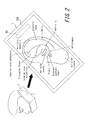
Fig. 2 illustrates a state where an electronic device is used; -
Figs. 3A and 3B illustrate a housing structure of an electronic device according to another embodiment; -
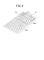
Fig. 4 illustrates one example of a vibration of a vibration plate in the electronic device according to the other embodiment; -
Fig. 5 illustrates one example of a vibration of a vibration plate when a display unit is not joined to a panel; and -
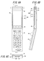
Figs. 6A and 6B illustrate a housing structure of an electronic device according to yet another embodiment. - Embodiments of the present invention will be described with reference to the accompanying drawings.
Fig. 1 is a function block diagram of anelectronic device 1 according to one embodiment of the present invention. Theelectronic device 1, which is a mobile phone (smartphone), for example, includes a vibration plate 100 (including apanel 10 and a display unit 20), apiezoelectric element 30, aninput unit 40, and acontrol unit 50. - The
panel 10 may be a touch panel configured to detect a contact, a cover panel configured to protect thedisplay unit 20, or the like. Thepanel 10 may be made of glass or a synthetic resin such as acryl. Thepanel 10 preferably has a plate shape. When thepanel 10 is the touch panel, thepanel 10 detects a contact made by a finger of a user, a pen, a stylus pen, or the like. The touch panel may detect a contact using any type, such as the capacitive type, the resistive film type, a surface acoustic wave type (or an ultrasonic type), an infrared type, an electromagnetic induction type, a load detection type, and the like. - The
display unit 20 is a panel display device such as a liquid crystal display, an organic EL display, and an inorganic EL display. Thedisplay unit 20 is disposed on a back surface of thepanel 10 as described later below. Thedisplay unit 20 may be adhered and fixed to thepanel 10 using a joining member (e.g. an adhesive agent). The joining member may be an elastic resin (e.g. an optical elastic resin) with a controlled refractive index for light transmitted therethrough. Thedisplay unit 20 displays various information through the joining member and thepanel 10. - The
piezoelectric element 30 is an element that is configured to undergo expansion and contraction in accordance with an electromechanical coupling factor of a constituent material in response to an electric signal (voltage) applied thereto. As a material of the element, ceramic and crystal are used, for example. Thepiezoelectric element 30 may be a unimorph, a bimorph, or a laminated piezoelectric element. The laminated piezoelectric element includes a laminated bimorph element in which layers (e.g. 16 or 24 layers) of bimorph are laminated. The laminated piezoelectric element is configured by a laminated structure of a plurality of dielectric layers made of PZT (lead zirconate titanate) and electrode layers each disposed between adjacent ones of the dielectric layers, for example. - The
piezoelectric element 30 is disposed on the back surface of thepanel 10. Thepiezoelectric element 30 is attached to thepanel 10 by a joining member (e.g. a double-sided adhesive tape). Thepiezoelectric element 30 undergoes expansion and contraction in response to an electric signal applied thereto, and accordingly, thepanel 10 is deformed. As a result, thevibration plate 100, which includes thepanel 10 and thedisplay unit 20, is vibrated in accordance with frequency(ies) or the like of the electric signal. - The
input unit 40 is configured to receive an operation input from the user and is configured using an operation button (an operation key), for example. When thepanel 10 is the touch panel, thepanel 10 also functions as an input unit that is capable of receiving an operation input from the user by detecting a contact made by the user. - The
control unit 50 is a processer configured to control theelectronic device 1 and apply a predetermined electric signal (voltage in accordance with a sound signal) to thepiezoelectric element 30. For example, the voltage applied to thepiezoelectric element 30 may be ± 15 V which is greater than ± 5 V, that is, a voltage to be applied to a so-called panel speaker configured for sound conduction not using human body vibration sound but using air conduction sound. With the above configuration, even when the user forcefully presses thevibration plate 100 against a user's body with force greater than or equal to 3 N, the vibration of thevibration plate 100 occurs. As a result, human body vibration sound which is transmitted through a part of the user's body is generated. Note that a level of the voltage to be applied is appropriately adjustable in accordance with how tightly the panel is fixed or in accordance with a capability of the element. When thecontrol unit 50 applies an electric signal to thepiezoelectric element 30, thepiezoelectric element 30 undergoes expansion and contraction in a longitudinal direction, and thevibration plate 100 is vibrated. Thepanel 10 undergoes flexure in response to expansion and contraction or flexture of thepiezoelectric element 30. Thepanel 10 is bent directly by thepiezoelectric element 30. The state in which the "panel 10 is bent directly by thepiezoelectric element 30" differs from a phenomenon in which the panel is deformed when pressing force is applied to a certain area of the panel due to inertial force of a piezoelectric actuator including the piezoelectric element provided in a casing as adopted in an existing panel speaker. The state in which the "panel 10 is bent directly by thepiezoelectric element 30" includes a state in which the panel is bent directly by expansion and contraction or bending (flexure) of the piezoelectric element via the joining member or via the joining member and a reinforcing member. Thus, thevibration plate 100 generates air conduction sound, and thevibration plate 100 also generates bone conduction sound that is transmitted through a part of the body when the user places the part of the body (e.g. the cartilaginous portion of the external ear) in contact with thevibration plate 100. For example, thecontrol unit 50 may cause a transmission andreception unit 60, which receives through wireless communication an electric signal corresponding to a sound signal representing voice of a party on the phone, music including a phone melody or a tune, or the like, to apply the received electric signal to thepiezoelectric element 30. By doing so, air conduction sound and bone conduction sound that correspond to the sound signal may be generated. The sound signal according to the electric signal may be based on music data stored in an internal memory or may be reproduced in accordance with music data stored in an external server and the like via the network. - The
control unit 50 also converts the sound signal collected by amicrophone 42 into a baseband signal and causes the transmission andreception unit 60 to transmit the baseband signal to an electronic device of the party on the phone. It is also possible to additionally provide theelectronic device 1 with adynamic speaker 62, so that thecontrol unit 50 outputs various sound signals to thedynamic speaker 62. - The vibration is caused in an area of the
vibration plate 100 where thepiezoelectric element 30 is joined to thepanel 10 and in other areas of thevibration plate 100 that are away from the area where thepiezoelectric element 30 is joined. Thevibration plate 100 is vibrated such that areas with relatively large amplitude of vibration and areas with relatively small amplitude of vibration are distributed randomly or in a cyclic manner across thevibration plate 100 at a certain moment. That is to say, thevibration plate 100 includes, in areas thereof that are vibrated, a plurality of portions that are configured to be vibrated in a direction intersecting with a main surface of thevibration plate 100. The vibration of a plurality of wavelengths is detected such that, in each of the plurality of portions, a value indicating amplitude of the vibration transitions over time from plus to minus or vice versa. The above configuration allows the user to listen to sound while placing the ear in contact with the areas of thevibration plate 100 that are away from the area where thepiezoelectric element 30 is joined, as illustrated inFig. 2 , for example. - In this regard, as illustrated in
Fig. 2 , thevibration plate 100 may be as large as the user's ear or may be larger than the user's ear. In the above cases, when the user listens to sound, the whole ear tends to be covered by thevibration plate 100 of theelectronic device 1. As a result, ambient sound (noise) is prevented from entering through the external auditory canal. It is suffice for the vibration to occur in an area of thevibration plate 100 that is larger than an area having a length corresponding to a distance from a helix to a tragus and an antitragus and a width corresponding to a distance from a crus helicis to an antihelix. Average ear size of the Japanese can be seen from the Japanese Body Dimension Database (1992-1994) or the like distributed by the Research Institute of Human Engineering for Quality Life (HQL). Thevibration plate 100 with a size greater than or equal to the average ear size of the Japanese would be generally capable of covering a whole ear of a foreigner as well. - The above
electronic device 1 is capable of transmitting, to the user, air conduction sound and human body vibration sound that is transmitted through a part of the user's body (e.g. the cartilaginous portion of the external ear). Accordingly, less volume of sound propagates to an external environment due to the vibration of air, compared to a case of the dynamic receiver. Accordingly, theelectronic device 1 is preferable for a situation where a recorded message is listened to on the train and the like, for example. - Furthermore, since the above
electronic device 1 transmits human body vibration sound by the vibration of thevibration plate 100, even when the user wears an earphone or a headphone, the user is able to listen to sound though the earphone or the headphone and a portion of the body by placing theelectronic device 1 in contact with the earphone and the headphone. - The above
electronic device 1 transmits sound to the user by the vibration of thevibration plate 100. Accordingly, in a case where theelectronic device 1 is not provided with an additional dynamic speaker, it is not necessary to provide the housing with an opening (i.e. a sound discharge opening) for sound transmission. As a result, a waterproof structure of the electronic device is simplified. When theelectronic device 1 is provided with the additional dynamic speaker, the sound discharge opening may be closed by a member that passes air through and blocks liquid. The member that passes air through and blocks liquid may be Gore-Tex™, for example. -
Figs. 3A and 3B illustrate the housing structure of theelectronic device 1 according to a first embodiment.Fig. 3A is a front view, andFig. 3B is a sectional view taken along a line b-b ofFig. 3A . Theelectronic device 1 illustrated inFigs. 3A and 3B is a smartphone in which the touch panel, i.e., a glass plate, is disposed as thepanel 10 on a front surface of a housing 60 (e.g. a metal or a resin casing). Thepanel 10 and theinput unit 40 are supported by thehousing 60, and thedisplay unit 20 and thepiezoelectric element 30 are each adhered to thepanel 10 by a joiningmember 70. Note that the joiningmember 70 may be the adhesive agent, the double-sided adhesive tape, or the like having thermosetting properties, ultraviolet-curable properties, or the like. For example, the joiningmember 70 may be an optical elastic resin, which is a colorless and transparent ultraviolet-curable acrylic adhesive agent. Thepanel 10, thedisplay unit 20, and thepiezoelectric element 30 each have a substantially rectangular shape. - The
display unit 20 is joined to thepanel 10 by the joiningmember 70, and thepanel 10 and thedisplay unit 20 form thevibration plate 100. Note that the joiningmember 70 may be the adhesive agent having thermosetting properties, ultraviolet-curable properties, or the like. For example, the joiningmember 70 may be an optical elastic resin, which is a colorless and transparent ultraviolet-curable acrylic adhesive agent. Thedisplay unit 20 is joined to the back surface of thepanel 10. Preferably, thedisplay unit 20 is adhered to thepanel 10 over substantially an entire surface area where thedisplay unit 20 is in contact with thepanel 10. With the above structure, rigidity of thevibration plate 100 is increased in a portion thereof where thedisplay unit 20 is joined to thepanel 10. - The
panel 10 is joined to thehousing 60 by a joining member. Using the joining member prevents the vibration of thevibration plate 100 from being transmitted directly to thehousing 60, thereby reducing the vibration of thehousing 60 itself compared to a case where the vibration of thevibration plate 100 is transmitted directly to thehousing 60. Consequently, the user is less likely to drop theelectronic device 1 due to a large vibration of thehousing 60. Furthermore, by using as the joining member the adhesive agent having thermosetting properties, ultraviolet-curable properties, or the like, for example, joining is achieved in a manner such that contraction due to a thermal stress is less likely to occur between thevibration plate 100 and thehousing 60. By using as the joining member the double-sided adhesive tape, for example, a contraction stress to thepiezoelectric element 30 is reduced compared to the case where the adhesive agent is used. - The
piezoelectric element 30 is also adhered to thepanel 10 by the joiningmember 70. By using the adhesive agent having thermosetting properties, ultraviolet-curable properties, or the like as the joiningmember 70, joining is achieved in a manner such that contraction due to the thermal stress is less likely to occur between thepiezoelectric element 30 and thevibration plate 100. The double-sided adhesive tape may also be used as the joiningmember 70. By using the double-sided adhesive tape, the contraction stress to thepiezoelectric element 30 is reduced compared to the case where the adhesive agent is used. - The
display unit 20 is disposed in substantially a middle of thepanel 10 in a short-side direction thereof. Thepiezoelectric element 30 is disposed near an end of thepanel 10 in the longitudinal direction of thepanel 10 at a predetermined distance from the end such that the longitudinal direction of thepiezoelectric element 30 extends along a short side of thepanel 10. Thedisplay unit 20 and thepiezoelectric element 30 are disposed side by side in a direction parallel to a surface of an inner side of thepanel 10. By disposing thepiezoelectric element 30 outside of the area where thepanel 10 covers thedisplay unit 20, display by thedisplay unit 20 is prevented from being interfering with by thepiezoelectric element 30. -
Fig. 4 illustrates one example of the vibration of thevibration plate 100 included in theelectronic device 1 according to the first embodiment. On the other hand,Fig. 5 illustrates one example of thevibration plate 100 not provided with thedisplay unit 20, in other words, one example of the vibration of thepanel 10 in which thedisplay unit 20 is not adhered to the back surface but supported by thehousing 60. In theelectronic device 1 according to the first embodiment, thedisplay unit 20 is adhered and fixed to thepanel 10. Accordingly, rigidity of thevibration plate 100 is higher in alower portion 100b thereof than in anupper portion 100a thereof. The above structure makes it possible to cause a larger vibration in theupper portion 100a of thevibration plate 100 that is attached with thepiezoelectric element 30 than in thelower portion 100b of thevibration plate 100, compared to the case ofFig. 5 not having thedisplay unit 20. As a result, sound leakage resulting from the vibration in thelower portion 100b of thevibration plate 100 that is not in contact with the user's ear is reduced in the lower 100b of thevibration plate 100. For example, when thepanel 10 has the rectangular shape, thepanel 10 tends to be bent in the longitudinal direction thereof, and the vibration is difficult to attenuate. However, by increasing rigidity of thevibration plate 100 by adhesion of thedisplay unit 20, attenuation of the vibration is increased, and the vibration in the lower portion of thevibration plate 100 may be reduced. Consequently, as illustrated inFig. 3A , for example, even when themicrophone 42 is provided in a lower part of the vibration plate 100 (i.e. near one end of thevibration plate 100 that opposes, across thedisplay unit 20, another end thereof provided with the piezoelectric element 30), sound leakage due to the vibration in the lower portion of thevibration plate 100 is less likely to be collected. Thevibration plate 100 in the upper portion thereof is bent directly by thepiezoelectric element 30, and the vibration in the lower portion is attenuated compared to the vibration in the upper portion. Thevibration plate 100 is bent by thepiezoelectric element 30 such that a portion of thevibration plate 100 directly above thepiezoelectric element 30 protrudes relative to neighboring portions of thevibration plate 100 in a long-side direction of thepiezoelectric element 30. - Note that an area which includes a joining portion for joining the piezoelectric element and to which the
display unit 20 is not joined has a width of from 0.5 cm to 5 cm in a first direction extending from the joining portion for thepiezoelectric element 30 included in the above area to an area where thedisplay unit 20 is joined. With the above structure, it is enabled that the area not to reduce the vibration has a sufficient size and that the electronic device is not oversized in a plane-view direction. - As described above, in the first embodiment, the
housing 60 and thevibration plate 100 are integrally configured by disposing thevibration plate 100 of theelectronic device 1 on the front surface of thehousing 60. Besides, thedisplay unit 20 and thepiezoelectric element 30 are adhered to thepanel 10 and housed within thehousing 60. Accordingly, portability of the electronic device is improved, and the risk of damage to the vibration body (i.e. the vibration plate) is reduced, compared to an electronic device provided with the vibration body protruding from the outer surface of the housing. Furthermore, by adhering and fixing thedisplay unit 20 to thepanel 10, rigidity of thevibration plate 100 is increased without using an additional member. As a result, sound leakage resulting from the vibration in the lower portion of thevibration plate 100 is reduced, and usability is improved. -
Figs. 6A and 6B illustrate the housing structure of theelectronic device 1 according to a second embodiment.Fig. 6A is a front view,Fig. 6B is a sectional view taken along a line b-b ofFig. 6A, and Fig. 6C is a sectional view taken along a line c-c ofFig. 6A . Theelectronic device 1 illustrated inFigs. 6A and 6B is a foldable mobile phone in which thevibration plate 100, which includes thedisplay unit 20 and a cover panel 10 (e.g. an acrylic plate) configured to protect thedisplay unit 20, is provided on a front surface of an upper portion of thehousing 60. Thedisplay unit 20 is joined to thepanel 10 by the joiningmember 70. In the second embodiment, a reinforcingplate 80 is disposed between thepanel 10 and thepiezoelectric element 30. The reinforcingplate 80 may be a resin plate, a metal plate, or a plate including glass fiber, for example. That is to say, theelectronic device 1 according to the second embodiment has a structure where thepiezoelectric element 30 and the reinforcingplate 80 are adhered by the joiningmember 70, and the reinforcingplate 80 and thepanel 10 are adhered by the joiningmember 70. - By disposing the reinforcing
plate 80 between thepiezoelectric element 30 and thepanel 10, when thevibration plate 100 is applied with an external force, for example, the applied external force is less likely to be transferred to thepiezoelectric element 30 and damage thepiezoelectric element 30. Even when thevibration plate 100 is forcefully pressed against the human body, attenuation in the vibration of thevibration plate 100 is reduced. Moreover, owing to the reinforcingplate 80 disposed between thepiezoelectric element 30 and thepanel 10, a resonance frequency of thepanel 10 is lowered, and a more preferable acoustic characteristic in a low frequency band is obtained. Note that instead of the reinforcing plate 80 a plate-shaped weight may be attached to thepiezoelectric element 30 by the joiningmember 70. - Although the present invention has been described based on the drawings and the embodiments thereof, it should be noted that a person skilled in the art may easily make a variety of modifications and alterations according to the present disclosure. Note that the modifications and alterations are within the scope of the present invention. For example, functions and the like included in the components and steps may be rearranged as long as the functions and the like are logically consistent. A plurality of component parts, the steps, and the like may also be integrated or separated.
- For example, the
piezoelectric element unit 30 may be disposed in a middle of thepanel 10. When thepiezoelectric element 30 is disposed in the middle of thepanel 10, the vibration of thepiezoelectric element 30 is evenly transmitted to thewhole vibration plate 100, thereby improving a quality of air conduction sound and allowing the user to perceive bone conduction sound even when the user places the ear in contact with thevibration plate 100 at different positions of thevibration plate 100. Note that, similarly to the first embodiment, thepiezoelectric element 30 may be provided in plurality. In this case also, thedisplay unit 20 is adhered and fixed to thepanel 10. By doing so, rigidity of other portions of thevibration plate 100 than the joining portion with thepiezoelectric element 30 is increased, and attenuation of the vibration is increased. As a result, sound leakage resulting from the vibration is reduced. - Although in the above
electronic device 1 thepiezoelectric element 30 is adhered to thepanel 10, thepiezoelectric element 30 may be attached to another place than thepanel 10. For example, thepiezoelectric element 30 may be adhered to a battery lid (a lid portion) that is configured to be attached to thehousing 60 to cover a battery (e.g. a rechargeable battery). In this case, the battery lid corresponds to the vibration plate. Since the battery lid is often attached to a surface different from thepanel 10 in theelectronic device 1 such as the mobile phone, the above structure enables the user to listen to sound by placing a portion of the body (e.g. the ear) in contact with the surface different from thepanel 10. In this case, it is preferable in terms of efficient transmission of bone conduction sound that the battery lid has a length in a longitudinal direction that is greater than or equal to the length from the antitragus to the inferior crus of antihelix and has a length in a short-side direction that is greater than or equal to the length from the tragus to the antihelix. When the battery lid is configured to have lower rigidity in a first area including a portion where the piezoelectric element is joined than in a second area located further away from the piezoelectric element than the first area is, the vibration from the first area to the second area is attenuated, and sound leakage resulting from the vibration is reduced. Rigidity of the second area may be increased for example by setting a thickness of the second area to be greater than a thickness of the first area in the battery lid or by joining another member (e.g. a member for holding the battery) to the second area. - Thus, according to the above embodiments, portability of the electronic device is improved, and favorable usability is provided.
-
- 1
- electronic device
- 10
- panel
- 20
- display unit
- 30
- piezoelectric element
- 40
- input unit
- 50
- control unit
- 60
- housing
- 70
- joining member
- 80
- reinforcing member
- 90
- support portion
- 100
- vibration plate
Claims (16)
- An electronic device comprising:a piezoelectric element;a vibration plate to which the piezoelectric element is joined for vibration; anda housing to which the vibration plate is joined, whereinvibration sound, which is transmitted by vibrating a part of a human body, is generated by the vibration plate, and whereinthe vibration plate includes, in a plan view thereof, a first area including a joining portion with the piezoelectric element and a second area located further away from the joining portion than the first area is, and rigidity in a first area is lower than rigidity in the second area.
- The electronic device of claim 1, wherein
the vibration plate includes two panels configured to be joined together, and a joining portion of the panels is located in the second area. - The electronic device of claim 2, wherein
one of the two panels comprises a display panel, and another one of the two panels comprises a touch panel or a protection panel disposed on an opposite side of the housing relative to the display panel. - The electronic device of any one of claims 1-3, wherein
a length of the vibration plate is greater than or equal to a length from an antitragus to an inferior crus of antihelix in a first direction extending from the joining portion with the piezoelectric element included in the first area to the second area. - The electronic device of any one of claims 1-4, wherein
a length of the vibration plate is greater than or equal to a length from a tragus to an antihelix in a second direction intersecting with the first direction extending from the joining portion with the piezoelectric element included in the first area to the second area. - The electronic device of any one of claims 1-5, wherein
the piezoelectric element is joined to the vibration plate by a joining member. - The electronic device of claim 6, wherein
the joining member comprises a non-thermosetting adhesive agent. - The electronic device of claim 6, wherein
the joining member comprises a double-sided adhesive tape. - The electronic device of any one of claims 1-8, wherein
the vibration plate is joined to the housing by a joining member. - The electronic device of claim 9, wherein
the joining member comprises a non-thermosetting adhesive agent. - The electronic device of claim 9, wherein
the joining member comprises a double-sided adhesive tape. - The electronic device of any one of claims 1-11, wherein
the vibration plate forms a part or an entirety of any of a display unit, an input unit, a cover of the display unit, and a lid portion that allows a battery to be detachable. - The electronic device of claim 3, wherein
the joining portion with the piezoelectric element in the vibration plate is located outside of an area where the touch panel covers the display panel. - The electronic device of claim 1, wherein
the first area has a width of from 0.5 cm to 5 cm in the first direction extending from the joining portion with the piezoelectric element included in the first area to the second area. - The electronic device of any one of claims 1-14, wherein
the vibration plate includes, in areas thereof that are vibrated, a plurality of portions that are configured to be vibrated in a direction intersecting with a surface of the vibration plate, and in each of the plurality of portions, a value indicating amplitude of the vibration transitions over time from plus to minus or vice versa. - The electronic device of claim 1, wherein the vibration plate is configured to generate the vibration sound and air conduction sound.
Applications Claiming Priority (2)
| Application Number | Priority Date | Filing Date | Title |
|---|---|---|---|
| JP2012077714A JP5855508B2 (en) | 2012-03-29 | 2012-03-29 | Electronics |
| PCT/JP2013/002138 WO2013145758A1 (en) | 2012-03-29 | 2013-03-28 | Electronic device |
Publications (3)
| Publication Number | Publication Date |
|---|---|
| EP2793484A1 true EP2793484A1 (en) | 2014-10-22 |
| EP2793484A4 EP2793484A4 (en) | 2015-08-05 |
| EP2793484B1 EP2793484B1 (en) | 2020-07-01 |
Family
ID=49259053
Family Applications (1)
| Application Number | Title | Priority Date | Filing Date |
|---|---|---|---|
| EP13768542.6A Not-in-force EP2793484B1 (en) | 2012-03-29 | 2013-03-28 | Electronic device |
Country Status (7)
| Country | Link |
|---|---|
| US (1) | US9143867B2 (en) |
| EP (1) | EP2793484B1 (en) |
| JP (6) | JP5855508B2 (en) |
| CN (1) | CN104025618B (en) |
| MX (1) | MX2014011441A (en) |
| RU (1) | RU2582893C2 (en) |
| WO (1) | WO2013145758A1 (en) |
Families Citing this family (21)
| Publication number | Priority date | Publication date | Assignee | Title |
|---|---|---|---|---|
| JP2013207601A (en) | 2012-03-28 | 2013-10-07 | Kyocera Corp | Electronic apparatus |
| US9619028B2 (en) * | 2012-03-29 | 2017-04-11 | Kyocera Corporation | Electronic apparatus and panel unit |
| JP5855508B2 (en) | 2012-03-29 | 2016-02-09 | 京セラ株式会社 | Electronics |
| JP5968018B2 (en) | 2012-04-10 | 2016-08-10 | 京セラ株式会社 | Electronics |
| JP5812926B2 (en) | 2012-04-12 | 2015-11-17 | 京セラ株式会社 | Electronics |
| JP5986417B2 (en) | 2012-04-12 | 2016-09-06 | 京セラ株式会社 | Electronics |
| JP5973218B2 (en) | 2012-04-26 | 2016-08-23 | 京セラ株式会社 | Electronics |
| JP5968061B2 (en) | 2012-05-01 | 2016-08-10 | 京セラ株式会社 | Electronics |
| US20140364967A1 (en) * | 2013-06-08 | 2014-12-11 | Scott Sullivan | System and Method for Controlling an Electronic Device |
| JP6001508B2 (en) * | 2013-06-26 | 2016-10-05 | 京セラ株式会社 | Electronics |
| JP6258667B2 (en) * | 2013-10-30 | 2018-01-10 | 京セラ株式会社 | Electronics |
| JP6258666B2 (en) * | 2013-10-30 | 2018-01-10 | 京セラ株式会社 | Electronics |
| US10491467B2 (en) * | 2014-05-23 | 2019-11-26 | Nant Holdings Ip, Llc | Fabric-based virtual air gap provisioning, systems and methods |
| JP6494980B2 (en) * | 2014-11-05 | 2019-04-03 | タイム技研株式会社 | Waterproof remote control |
| KR102164704B1 (en) * | 2015-11-13 | 2020-10-12 | 삼성전자주식회사 | Electronic device with metal frame antenna |
| CN106502329A (en) * | 2016-10-28 | 2017-03-15 | 努比亚技术有限公司 | A kind of terminal unit |
| KR102386452B1 (en) * | 2018-05-02 | 2022-04-14 | 삼성디스플레이 주식회사 | Display device |
| CN110049415B (en) | 2019-03-19 | 2021-06-01 | 华为技术有限公司 | Vibration sound production device and electronic equipment |
| KR102662671B1 (en) | 2019-03-29 | 2024-04-30 | 엘지디스플레이 주식회사 | Display apparatus |
| CN114449417B (en) * | 2020-10-30 | 2022-11-25 | 华为技术有限公司 | Speakers and Electronics |
| MX2023003574A (en) | 2021-01-14 | 2023-04-04 | Shenzhen Shokz Co Ltd | Bone conduction speaker. |
Family Cites Families (65)
| Publication number | Priority date | Publication date | Assignee | Title |
|---|---|---|---|---|
| US3728741A (en) | 1970-12-28 | 1973-04-24 | M Lepor | Noise protective device |
| JPH0246159Y2 (en) * | 1985-11-20 | 1990-12-05 | ||
| JPH07296786A (en) | 1994-04-22 | 1995-11-10 | Matsushita Electric Ind Co Ltd | Battery case |
| JPH08223675A (en) | 1995-02-17 | 1996-08-30 | Alpine Electron Inc | Speaker device |
| JPH09247795A (en) * | 1996-03-05 | 1997-09-19 | Hokuriku Electric Ind Co Ltd | Piezoelectric transducer and sounding electronic device |
| JP3168946B2 (en) | 1997-06-27 | 2001-05-21 | 岩崎通信機株式会社 | Battery lid waterproof structure for portable electronic devices |
| SK20292000A3 (en) | 1998-07-03 | 2001-06-11 | New Transducers Limited | Resonant panel-form loudspeaker |
| GB9818719D0 (en) | 1998-08-28 | 1998-10-21 | New Transducers Ltd | Vubration exciter |
| WO2000013392A2 (en) | 1998-08-31 | 2000-03-09 | The Government Of The United States Of America, As Represented By The Administrator Of The National Aeronautics And Space Administration (Nasa) | Piezoelectric vibrational and acoustic alert device |
| JP3597061B2 (en) | 1998-11-13 | 2004-12-02 | 日本電気株式会社 | Piezo speaker |
| JP3771086B2 (en) | 1999-06-18 | 2006-04-26 | 三菱電機株式会社 | Portable terminal |
| JP2002027065A (en) | 2000-07-05 | 2002-01-25 | Hitachi Ltd | Mobile terminal device |
| US6639988B2 (en) | 2000-08-31 | 2003-10-28 | Delphi Technologies, Inc. | Piezo integrated flat speakers for automotive interior panels |
| JP3632594B2 (en) | 2000-11-28 | 2005-03-23 | 日本電気株式会社 | Electronic equipment |
| JP2002185593A (en) | 2000-12-19 | 2002-06-28 | Hitachi Kokusai Electric Inc | Mobile phone |
| JP2002219413A (en) * | 2001-01-30 | 2002-08-06 | Nec Tokin Corp | Multifunctional vibration actuator |
| JP2002232542A (en) | 2001-02-06 | 2002-08-16 | Taisei Plas Co Ltd | Portable communication equipment |
| JP3709350B2 (en) | 2001-04-06 | 2005-10-26 | 埼玉日本電気株式会社 | Foldable information terminal |
| DE60226098T2 (en) | 2001-06-28 | 2009-06-18 | Panasonic Corp., Kadoma | Speaker system, mobile terminal and electronic device |
| RU2212736C2 (en) * | 2001-11-12 | 2003-09-20 | Научное конструкторско-технологическое бюро "Пьезоприбор" Ростовского государственного университета | Bender transducer |
| CN1279871C (en) | 2002-02-18 | 2006-10-18 | 吉峰贵司 | Diagnostic system and portable telephone device |
| EP1542064A4 (en) * | 2002-09-03 | 2008-02-20 | Sharp Kk | Liquid crystal display device having sound output function and the like and electronic device using the same |
| JP2004187031A (en) * | 2002-12-04 | 2004-07-02 | Temuko Japan:Kk | Mobile phone using bone conduction speaker |
| DE602004005342D1 (en) | 2003-05-28 | 2007-04-26 | Koninkl Philips Electronics Nv | AS A SPEAKER SERVING DISPLAY |
| US7421088B2 (en) | 2003-08-28 | 2008-09-02 | Motorola, Inc. | Multifunction transducer |
| JP4359757B2 (en) | 2003-09-17 | 2009-11-04 | ソニー株式会社 | Information display device |
| US7512425B2 (en) | 2004-01-16 | 2009-03-31 | Temco Japan Co., Ltd. | Portable telephone using bone conduction device |
| JP4361384B2 (en) | 2004-01-29 | 2009-11-11 | セイコーインスツル株式会社 | Portable electronic device with sound reporting function |
| JP2005236352A (en) * | 2004-02-17 | 2005-09-02 | Authentic Ltd | Panel type speaker for display device |
| JP4449534B2 (en) | 2004-03-30 | 2010-04-14 | セイコーエプソン株式会社 | Electro-optical device and electronic apparatus |
| JP2005348193A (en) * | 2004-06-04 | 2005-12-15 | Nec Tokin Corp | Receiver |
| JP2006094072A (en) * | 2004-09-22 | 2006-04-06 | Citizen Electronics Co Ltd | Flat speaker |
| JP4700323B2 (en) | 2004-10-28 | 2011-06-15 | ホシデン株式会社 | Flat panel speaker |
| WO2006059679A1 (en) | 2004-12-02 | 2006-06-08 | Matsushita Electric Industrial Co., Ltd. | Portable terminal apparatus |
| JP4507252B2 (en) | 2004-12-27 | 2010-07-21 | シチズン電子株式会社 | Panel type speaker |
| JP4174471B2 (en) * | 2004-12-28 | 2008-10-29 | 埼玉日本電気株式会社 | Flat panel speaker and its mounting structure |
| JP4611381B2 (en) | 2005-04-22 | 2011-01-12 | シャープ株式会社 | Card type device |
| JP4515348B2 (en) * | 2005-07-26 | 2010-07-28 | Necトーキン株式会社 | Piezoelectric device for generating acoustic signals |
| JP4779526B2 (en) * | 2005-09-15 | 2011-09-28 | 日本電気株式会社 | Panel speaker |
| JP5208362B2 (en) | 2005-10-28 | 2013-06-12 | ソニー株式会社 | Electronics |
| EP1947901A4 (en) | 2005-11-02 | 2011-02-09 | Nec Corp | Speaker, image element protective screen, case of terminal, and terminal |
| JP2007180827A (en) * | 2005-12-27 | 2007-07-12 | Citizen Electronics Co Ltd | Panel-type speaker |
| JP2007189578A (en) | 2006-01-16 | 2007-07-26 | Nec Tokin Corp | Receiving device and portable telephone |
| JP4861079B2 (en) | 2006-07-10 | 2012-01-25 | Necトーキン株式会社 | Bone conduction receiver |
| KR101353417B1 (en) | 2007-03-16 | 2014-01-22 | 엘지전자 주식회사 | Portable terminal |
| JP2008270879A (en) | 2007-04-16 | 2008-11-06 | Nec Tokin Corp | Receiver |
| JP2009118396A (en) | 2007-11-09 | 2009-05-28 | Nec Tokin Corp | Transceiver apparatus |
| JP2009147410A (en) | 2007-12-11 | 2009-07-02 | Sony Corp | Playback apparatus, playback method, and playback system |
| US20100278362A1 (en) | 2007-12-20 | 2010-11-04 | Kim David K J | Method and apparatus to interchange between bone conductive and normal mode in receiver |
| CN101594401B (en) | 2008-05-27 | 2013-06-05 | 深圳富泰宏精密工业有限公司 | Electronic device with receiver |
| US20100225600A1 (en) | 2009-03-09 | 2010-09-09 | Motorola Inc. | Display Structure with Direct Piezoelectric Actuation |
| JP2011091719A (en) * | 2009-10-26 | 2011-05-06 | Authentic Ltd | Flexural oscillating actuator |
| JP5576690B2 (en) | 2010-03-26 | 2014-08-20 | 京セラ株式会社 | Portable wireless device |
| KR101153553B1 (en) * | 2010-07-28 | 2012-06-11 | 삼성전기주식회사 | Vibrator and electronic apparatus having thereof |
| CN103154857B (en) | 2010-08-23 | 2019-03-15 | 诺基亚技术有限公司 | Apparatus and method for providing haptic and audio feedback in a touch-sensitive user interface |
| US8279623B2 (en) | 2010-12-22 | 2012-10-02 | Research In Motion Limited | Apparatus for vibrating a portable electronic device |
| JP6133534B2 (en) | 2011-11-18 | 2017-05-24 | 株式会社ファインウェル | Mobile phone and its integrated circuit |
| KR101068254B1 (en) | 2011-02-01 | 2011-09-28 | 주식회사 보니아코퍼레이션 | Communication terminal with bone conduction function |
| US9020168B2 (en) | 2011-08-30 | 2015-04-28 | Nokia Corporation | Apparatus and method for audio delivery with different sound conduction transducers |
| JP2013255212A (en) | 2011-09-13 | 2013-12-19 | Kddi Corp | Telephone call device |
| KR101332553B1 (en) | 2011-12-20 | 2013-11-22 | 엘지전자 주식회사 | Mobile terminal |
| JP2013207601A (en) | 2012-03-28 | 2013-10-07 | Kyocera Corp | Electronic apparatus |
| JP5855508B2 (en) | 2012-03-29 | 2016-02-09 | 京セラ株式会社 | Electronics |
| JP5812926B2 (en) | 2012-04-12 | 2015-11-17 | 京セラ株式会社 | Electronics |
| JP5968061B2 (en) | 2012-05-01 | 2016-08-10 | 京セラ株式会社 | Electronics |
-
2012
- 2012-03-29 JP JP2012077714A patent/JP5855508B2/en not_active Expired - Fee Related
- 2012-07-02 JP JP2012148809A patent/JP5270783B1/en not_active Expired - Fee Related
-
2013
- 2013-03-28 WO PCT/JP2013/002138 patent/WO2013145758A1/en not_active Ceased
- 2013-03-28 MX MX2014011441A patent/MX2014011441A/en unknown
- 2013-03-28 US US14/002,698 patent/US9143867B2/en active Active
- 2013-03-28 CN CN201380004466.2A patent/CN104025618B/en not_active Expired - Fee Related
- 2013-03-28 EP EP13768542.6A patent/EP2793484B1/en not_active Not-in-force
- 2013-03-28 RU RU2014134026/28A patent/RU2582893C2/en active
- 2013-10-30 JP JP2013225807A patent/JP5484625B2/en not_active Expired - Fee Related
- 2013-10-30 JP JP2013225856A patent/JP5484626B2/en not_active Expired - Fee Related
- 2013-10-30 JP JP2013225857A patent/JP5484627B2/en not_active Expired - Fee Related
-
2014
- 2014-01-30 JP JP2014016046A patent/JP5818921B2/en not_active Expired - Fee Related
Also Published As
| Publication number | Publication date |
|---|---|
| JP5484626B2 (en) | 2014-05-07 |
| MX2014011441A (en) | 2014-11-10 |
| JP5855508B2 (en) | 2016-02-09 |
| US9143867B2 (en) | 2015-09-22 |
| JP2014053947A (en) | 2014-03-20 |
| JP5484625B2 (en) | 2014-05-07 |
| CN104025618A (en) | 2014-09-03 |
| WO2013145758A1 (en) | 2013-10-03 |
| JP2014112916A (en) | 2014-06-19 |
| JP5818921B2 (en) | 2015-11-18 |
| RU2582893C2 (en) | 2016-04-27 |
| JP2014053946A (en) | 2014-03-20 |
| US20150030188A1 (en) | 2015-01-29 |
| JP5484627B2 (en) | 2014-05-07 |
| JP5270783B1 (en) | 2013-08-21 |
| JP2013207795A (en) | 2013-10-07 |
| JP2014053948A (en) | 2014-03-20 |
| CN104025618B (en) | 2017-06-23 |
| EP2793484B1 (en) | 2020-07-01 |
| JP2013207749A (en) | 2013-10-07 |
| EP2793484A4 (en) | 2015-08-05 |
| RU2014134026A (en) | 2016-03-20 |
Similar Documents
| Publication | Publication Date | Title |
|---|---|---|
| EP2793484B1 (en) | Electronic device | |
| US9591389B2 (en) | Electronic device | |
| EP2793486B1 (en) | Electronic apparatus | |
| US9191749B2 (en) | Electronic device that vibrates an element for sound transmission | |
| EP2800395B1 (en) | Electronic device | |
| US9571932B2 (en) | Electronic device | |
| US9438990B2 (en) | Electronic device |
Legal Events
| Date | Code | Title | Description |
|---|---|---|---|
| PUAI | Public reference made under article 153(3) epc to a published international application that has entered the european phase |
Free format text: ORIGINAL CODE: 0009012 |
|
| 17P | Request for examination filed |
Effective date: 20140528 |
|
| AK | Designated contracting states |
Kind code of ref document: A1 Designated state(s): AL AT BE BG CH CY CZ DE DK EE ES FI FR GB GR HR HU IE IS IT LI LT LU LV MC MK MT NL NO PL PT RO RS SE SI SK SM TR |
|
| DAX | Request for extension of the european patent (deleted) | ||
| RA4 | Supplementary search report drawn up and despatched (corrected) |
Effective date: 20150706 |
|
| RIC1 | Information provided on ipc code assigned before grant |
Ipc: H04R 7/06 20060101ALN20150630BHEP Ipc: H04M 1/03 20060101ALI20150630BHEP Ipc: H04R 7/04 20060101AFI20150630BHEP Ipc: H04R 17/00 20060101ALI20150630BHEP |
|
| 17Q | First examination report despatched |
Effective date: 20160713 |
|
| STAA | Information on the status of an ep patent application or granted ep patent |
Free format text: STATUS: EXAMINATION IS IN PROGRESS |
|
| REG | Reference to a national code |
Ref country code: DE Ref legal event code: R079 Ref document number: 602013070332 Country of ref document: DE Free format text: PREVIOUS MAIN CLASS: H04R0001000000 Ipc: H04R0007040000 |
|
| GRAP | Despatch of communication of intention to grant a patent |
Free format text: ORIGINAL CODE: EPIDOSNIGR1 |
|
| STAA | Information on the status of an ep patent application or granted ep patent |
Free format text: STATUS: GRANT OF PATENT IS INTENDED |
|
| RIC1 | Information provided on ipc code assigned before grant |
Ipc: H04R 7/06 20060101ALN20200106BHEP Ipc: H04M 1/03 20060101ALI20200106BHEP Ipc: H04R 17/00 20060101ALI20200106BHEP Ipc: H04R 7/04 20060101AFI20200106BHEP |
|
| RIC1 | Information provided on ipc code assigned before grant |
Ipc: H04R 7/06 20060101ALN20200114BHEP Ipc: H04R 17/00 20060101ALI20200114BHEP Ipc: H04R 7/04 20060101AFI20200114BHEP Ipc: H04M 1/03 20060101ALI20200114BHEP |
|
| INTG | Intention to grant announced |
Effective date: 20200203 |
|
| GRAS | Grant fee paid |
Free format text: ORIGINAL CODE: EPIDOSNIGR3 |
|
| GRAA | (expected) grant |
Free format text: ORIGINAL CODE: 0009210 |
|
| STAA | Information on the status of an ep patent application or granted ep patent |
Free format text: STATUS: THE PATENT HAS BEEN GRANTED |
|
| AK | Designated contracting states |
Kind code of ref document: B1 Designated state(s): AL AT BE BG CH CY CZ DE DK EE ES FI FR GB GR HR HU IE IS IT LI LT LU LV MC MK MT NL NO PL PT RO RS SE SI SK SM TR |
|
| REG | Reference to a national code |
Ref country code: CH Ref legal event code: EP Ref country code: AT Ref legal event code: REF Ref document number: 1287296 Country of ref document: AT Kind code of ref document: T Effective date: 20200715 |
|
| REG | Reference to a national code |
Ref country code: IE Ref legal event code: FG4D |
|
| REG | Reference to a national code |
Ref country code: DE Ref legal event code: R096 Ref document number: 602013070332 Country of ref document: DE |
|
| REG | Reference to a national code |
Ref country code: LT Ref legal event code: MG4D |
|
| PG25 | Lapsed in a contracting state [announced via postgrant information from national office to epo] |
Ref country code: BG Free format text: LAPSE BECAUSE OF FAILURE TO SUBMIT A TRANSLATION OF THE DESCRIPTION OR TO PAY THE FEE WITHIN THE PRESCRIBED TIME-LIMIT Effective date: 20201001 |
|
| REG | Reference to a national code |
Ref country code: NL Ref legal event code: MP Effective date: 20200701 |
|
| REG | Reference to a national code |
Ref country code: AT Ref legal event code: MK05 Ref document number: 1287296 Country of ref document: AT Kind code of ref document: T Effective date: 20200701 |
|
| PG25 | Lapsed in a contracting state [announced via postgrant information from national office to epo] |
Ref country code: AT Free format text: LAPSE BECAUSE OF FAILURE TO SUBMIT A TRANSLATION OF THE DESCRIPTION OR TO PAY THE FEE WITHIN THE PRESCRIBED TIME-LIMIT Effective date: 20200701 Ref country code: SE Free format text: LAPSE BECAUSE OF FAILURE TO SUBMIT A TRANSLATION OF THE DESCRIPTION OR TO PAY THE FEE WITHIN THE PRESCRIBED TIME-LIMIT Effective date: 20200701 Ref country code: GR Free format text: LAPSE BECAUSE OF FAILURE TO SUBMIT A TRANSLATION OF THE DESCRIPTION OR TO PAY THE FEE WITHIN THE PRESCRIBED TIME-LIMIT Effective date: 20201002 Ref country code: HR Free format text: LAPSE BECAUSE OF FAILURE TO SUBMIT A TRANSLATION OF THE DESCRIPTION OR TO PAY THE FEE WITHIN THE PRESCRIBED TIME-LIMIT Effective date: 20200701 Ref country code: NO Free format text: LAPSE BECAUSE OF FAILURE TO SUBMIT A TRANSLATION OF THE DESCRIPTION OR TO PAY THE FEE WITHIN THE PRESCRIBED TIME-LIMIT Effective date: 20201001 Ref country code: FI Free format text: LAPSE BECAUSE OF FAILURE TO SUBMIT A TRANSLATION OF THE DESCRIPTION OR TO PAY THE FEE WITHIN THE PRESCRIBED TIME-LIMIT Effective date: 20200701 Ref country code: ES Free format text: LAPSE BECAUSE OF FAILURE TO SUBMIT A TRANSLATION OF THE DESCRIPTION OR TO PAY THE FEE WITHIN THE PRESCRIBED TIME-LIMIT Effective date: 20200701 Ref country code: LT Free format text: LAPSE BECAUSE OF FAILURE TO SUBMIT A TRANSLATION OF THE DESCRIPTION OR TO PAY THE FEE WITHIN THE PRESCRIBED TIME-LIMIT Effective date: 20200701 Ref country code: CZ Free format text: LAPSE BECAUSE OF FAILURE TO SUBMIT A TRANSLATION OF THE DESCRIPTION OR TO PAY THE FEE WITHIN THE PRESCRIBED TIME-LIMIT Effective date: 20200701 Ref country code: PT Free format text: LAPSE BECAUSE OF FAILURE TO SUBMIT A TRANSLATION OF THE DESCRIPTION OR TO PAY THE FEE WITHIN THE PRESCRIBED TIME-LIMIT Effective date: 20201102 |
|
| PG25 | Lapsed in a contracting state [announced via postgrant information from national office to epo] |
Ref country code: LV Free format text: LAPSE BECAUSE OF FAILURE TO SUBMIT A TRANSLATION OF THE DESCRIPTION OR TO PAY THE FEE WITHIN THE PRESCRIBED TIME-LIMIT Effective date: 20200701 Ref country code: PL Free format text: LAPSE BECAUSE OF FAILURE TO SUBMIT A TRANSLATION OF THE DESCRIPTION OR TO PAY THE FEE WITHIN THE PRESCRIBED TIME-LIMIT Effective date: 20200701 Ref country code: RS Free format text: LAPSE BECAUSE OF FAILURE TO SUBMIT A TRANSLATION OF THE DESCRIPTION OR TO PAY THE FEE WITHIN THE PRESCRIBED TIME-LIMIT Effective date: 20200701 Ref country code: IS Free format text: LAPSE BECAUSE OF FAILURE TO SUBMIT A TRANSLATION OF THE DESCRIPTION OR TO PAY THE FEE WITHIN THE PRESCRIBED TIME-LIMIT Effective date: 20201101 |
|
| PG25 | Lapsed in a contracting state [announced via postgrant information from national office to epo] |
Ref country code: NL Free format text: LAPSE BECAUSE OF FAILURE TO SUBMIT A TRANSLATION OF THE DESCRIPTION OR TO PAY THE FEE WITHIN THE PRESCRIBED TIME-LIMIT Effective date: 20200701 |
|
| REG | Reference to a national code |
Ref country code: DE Ref legal event code: R097 Ref document number: 602013070332 Country of ref document: DE |
|
| PG25 | Lapsed in a contracting state [announced via postgrant information from national office to epo] |
Ref country code: SM Free format text: LAPSE BECAUSE OF FAILURE TO SUBMIT A TRANSLATION OF THE DESCRIPTION OR TO PAY THE FEE WITHIN THE PRESCRIBED TIME-LIMIT Effective date: 20200701 Ref country code: RO Free format text: LAPSE BECAUSE OF FAILURE TO SUBMIT A TRANSLATION OF THE DESCRIPTION OR TO PAY THE FEE WITHIN THE PRESCRIBED TIME-LIMIT Effective date: 20200701 Ref country code: EE Free format text: LAPSE BECAUSE OF FAILURE TO SUBMIT A TRANSLATION OF THE DESCRIPTION OR TO PAY THE FEE WITHIN THE PRESCRIBED TIME-LIMIT Effective date: 20200701 Ref country code: DK Free format text: LAPSE BECAUSE OF FAILURE TO SUBMIT A TRANSLATION OF THE DESCRIPTION OR TO PAY THE FEE WITHIN THE PRESCRIBED TIME-LIMIT Effective date: 20200701 Ref country code: IT Free format text: LAPSE BECAUSE OF FAILURE TO SUBMIT A TRANSLATION OF THE DESCRIPTION OR TO PAY THE FEE WITHIN THE PRESCRIBED TIME-LIMIT Effective date: 20200701 |
|
| PLBE | No opposition filed within time limit |
Free format text: ORIGINAL CODE: 0009261 |
|
| STAA | Information on the status of an ep patent application or granted ep patent |
Free format text: STATUS: NO OPPOSITION FILED WITHIN TIME LIMIT |
|
| PG25 | Lapsed in a contracting state [announced via postgrant information from national office to epo] |
Ref country code: AL Free format text: LAPSE BECAUSE OF FAILURE TO SUBMIT A TRANSLATION OF THE DESCRIPTION OR TO PAY THE FEE WITHIN THE PRESCRIBED TIME-LIMIT Effective date: 20200701 |
|
| PGFP | Annual fee paid to national office [announced via postgrant information from national office to epo] |
Ref country code: GB Payment date: 20210318 Year of fee payment: 9 |
|
| 26N | No opposition filed |
Effective date: 20210406 |
|
| PG25 | Lapsed in a contracting state [announced via postgrant information from national office to epo] |
Ref country code: SK Free format text: LAPSE BECAUSE OF FAILURE TO SUBMIT A TRANSLATION OF THE DESCRIPTION OR TO PAY THE FEE WITHIN THE PRESCRIBED TIME-LIMIT Effective date: 20200701 |
|
| PG25 | Lapsed in a contracting state [announced via postgrant information from national office to epo] |
Ref country code: SI Free format text: LAPSE BECAUSE OF FAILURE TO SUBMIT A TRANSLATION OF THE DESCRIPTION OR TO PAY THE FEE WITHIN THE PRESCRIBED TIME-LIMIT Effective date: 20200701 |
|
| PG25 | Lapsed in a contracting state [announced via postgrant information from national office to epo] |
Ref country code: MC Free format text: LAPSE BECAUSE OF FAILURE TO SUBMIT A TRANSLATION OF THE DESCRIPTION OR TO PAY THE FEE WITHIN THE PRESCRIBED TIME-LIMIT Effective date: 20200701 |
|
| REG | Reference to a national code |
Ref country code: CH Ref legal event code: PL |
|
| REG | Reference to a national code |
Ref country code: BE Ref legal event code: MM Effective date: 20210331 |
|
| PG25 | Lapsed in a contracting state [announced via postgrant information from national office to epo] |
Ref country code: CH Free format text: LAPSE BECAUSE OF NON-PAYMENT OF DUE FEES Effective date: 20210331 Ref country code: LI Free format text: LAPSE BECAUSE OF NON-PAYMENT OF DUE FEES Effective date: 20210331 Ref country code: LU Free format text: LAPSE BECAUSE OF NON-PAYMENT OF DUE FEES Effective date: 20210328 Ref country code: IE Free format text: LAPSE BECAUSE OF NON-PAYMENT OF DUE FEES Effective date: 20210328 Ref country code: FR Free format text: LAPSE BECAUSE OF NON-PAYMENT OF DUE FEES Effective date: 20210331 |
|
| PG25 | Lapsed in a contracting state [announced via postgrant information from national office to epo] |
Ref country code: BE Free format text: LAPSE BECAUSE OF NON-PAYMENT OF DUE FEES Effective date: 20210331 |
|
| GBPC | Gb: european patent ceased through non-payment of renewal fee |
Effective date: 20220328 |
|
| PG25 | Lapsed in a contracting state [announced via postgrant information from national office to epo] |
Ref country code: GB Free format text: LAPSE BECAUSE OF NON-PAYMENT OF DUE FEES Effective date: 20220328 |
|
| PG25 | Lapsed in a contracting state [announced via postgrant information from national office to epo] |
Ref country code: HU Free format text: LAPSE BECAUSE OF FAILURE TO SUBMIT A TRANSLATION OF THE DESCRIPTION OR TO PAY THE FEE WITHIN THE PRESCRIBED TIME-LIMIT; INVALID AB INITIO Effective date: 20130328 |
|
| P01 | Opt-out of the competence of the unified patent court (upc) registered |
Effective date: 20230505 |
|
| PG25 | Lapsed in a contracting state [announced via postgrant information from national office to epo] |
Ref country code: CY Free format text: LAPSE BECAUSE OF FAILURE TO SUBMIT A TRANSLATION OF THE DESCRIPTION OR TO PAY THE FEE WITHIN THE PRESCRIBED TIME-LIMIT Effective date: 20200701 |
|
| PG25 | Lapsed in a contracting state [announced via postgrant information from national office to epo] |
Ref country code: MK Free format text: LAPSE BECAUSE OF FAILURE TO SUBMIT A TRANSLATION OF THE DESCRIPTION OR TO PAY THE FEE WITHIN THE PRESCRIBED TIME-LIMIT Effective date: 20200701 |
|
| PGFP | Annual fee paid to national office [announced via postgrant information from national office to epo] |
Ref country code: DE Payment date: 20240130 Year of fee payment: 12 |
|
| PG25 | Lapsed in a contracting state [announced via postgrant information from national office to epo] |
Ref country code: TR Free format text: LAPSE BECAUSE OF FAILURE TO SUBMIT A TRANSLATION OF THE DESCRIPTION OR TO PAY THE FEE WITHIN THE PRESCRIBED TIME-LIMIT Effective date: 20200701 |
|
| PG25 | Lapsed in a contracting state [announced via postgrant information from national office to epo] |
Ref country code: MT Free format text: LAPSE BECAUSE OF FAILURE TO SUBMIT A TRANSLATION OF THE DESCRIPTION OR TO PAY THE FEE WITHIN THE PRESCRIBED TIME-LIMIT Effective date: 20200701 |
|
| REG | Reference to a national code |
Ref country code: DE Ref legal event code: R119 Ref document number: 602013070332 Country of ref document: DE |
|
| PG25 | Lapsed in a contracting state [announced via postgrant information from national office to epo] |
Ref country code: DE Free format text: LAPSE BECAUSE OF NON-PAYMENT OF DUE FEES Effective date: 20251001 |