EP2793361B1 - Rotierende elektrische Maschine - Google Patents
Rotierende elektrische Maschine Download PDFInfo
- Publication number
- EP2793361B1 EP2793361B1 EP13164083.1A EP13164083A EP2793361B1 EP 2793361 B1 EP2793361 B1 EP 2793361B1 EP 13164083 A EP13164083 A EP 13164083A EP 2793361 B1 EP2793361 B1 EP 2793361B1
- Authority
- EP
- European Patent Office
- Prior art keywords
- electric machine
- rotating electric
- stator
- laminated core
- torque
- Prior art date
- Legal status (The legal status is an assumption and is not a legal conclusion. Google has not performed a legal analysis and makes no representation as to the accuracy of the status listed.)
- Not-in-force
Links
- 238000013016 damping Methods 0.000 claims description 33
- 238000001816 cooling Methods 0.000 claims description 13
- 239000011358 absorbing material Substances 0.000 claims description 3
- 239000003302 ferromagnetic material Substances 0.000 claims description 3
- 238000003466 welding Methods 0.000 claims description 3
- 229910001060 Gray iron Inorganic materials 0.000 description 9
- 238000010276 construction Methods 0.000 description 7
- 238000010586 diagram Methods 0.000 description 6
- 239000002184 metal Substances 0.000 description 6
- 229910052751 metal Inorganic materials 0.000 description 6
- 238000000034 method Methods 0.000 description 5
- 238000004804 winding Methods 0.000 description 5
- 230000008901 benefit Effects 0.000 description 4
- 230000008878 coupling Effects 0.000 description 3
- 238000010168 coupling process Methods 0.000 description 3
- 238000005859 coupling reaction Methods 0.000 description 3
- 230000000694 effects Effects 0.000 description 3
- 230000004907 flux Effects 0.000 description 3
- 230000006872 improvement Effects 0.000 description 3
- 230000005291 magnetic effect Effects 0.000 description 3
- 238000004519 manufacturing process Methods 0.000 description 3
- 230000008569 process Effects 0.000 description 3
- 229910000831 Steel Inorganic materials 0.000 description 2
- 238000004026 adhesive bonding Methods 0.000 description 2
- 230000005540 biological transmission Effects 0.000 description 2
- 238000006243 chemical reaction Methods 0.000 description 2
- 150000001875 compounds Chemical class 0.000 description 2
- 238000005516 engineering process Methods 0.000 description 2
- 239000006260 foam Substances 0.000 description 2
- 238000005304 joining Methods 0.000 description 2
- 239000000463 material Substances 0.000 description 2
- 239000004033 plastic Substances 0.000 description 2
- 229920003023 plastic Polymers 0.000 description 2
- 230000001681 protective effect Effects 0.000 description 2
- 230000009467 reduction Effects 0.000 description 2
- 239000010959 steel Substances 0.000 description 2
- 230000001360 synchronised effect Effects 0.000 description 2
- 229920002430 Fibre-reinforced plastic Polymers 0.000 description 1
- 230000009471 action Effects 0.000 description 1
- 230000004913 activation Effects 0.000 description 1
- 238000005452 bending Methods 0.000 description 1
- 238000005266 casting Methods 0.000 description 1
- 239000002131 composite material Substances 0.000 description 1
- 239000002826 coolant Substances 0.000 description 1
- 230000002349 favourable effect Effects 0.000 description 1
- 230000005294 ferromagnetic effect Effects 0.000 description 1
- 239000011151 fibre-reinforced plastic Substances 0.000 description 1
- 239000002657 fibrous material Substances 0.000 description 1
- 210000004907 gland Anatomy 0.000 description 1
- 238000009434 installation Methods 0.000 description 1
- 239000011810 insulating material Substances 0.000 description 1
- 230000003993 interaction Effects 0.000 description 1
- 238000012423 maintenance Methods 0.000 description 1
- 239000002557 mineral fiber Substances 0.000 description 1
- 239000011490 mineral wool Substances 0.000 description 1
- 238000000465 moulding Methods 0.000 description 1
- 230000002093 peripheral effect Effects 0.000 description 1
- 239000011148 porous material Substances 0.000 description 1
- 230000008439 repair process Effects 0.000 description 1
- 238000005476 soldering Methods 0.000 description 1
- 238000003860 storage Methods 0.000 description 1
- 230000001629 suppression Effects 0.000 description 1
- 230000002277 temperature effect Effects 0.000 description 1
- 238000009423 ventilation Methods 0.000 description 1
- XLYOFNOQVPJJNP-UHFFFAOYSA-N water Substances O XLYOFNOQVPJJNP-UHFFFAOYSA-N 0.000 description 1
Images

Classifications
-
- H—ELECTRICITY
- H02—GENERATION; CONVERSION OR DISTRIBUTION OF ELECTRIC POWER
- H02K—DYNAMO-ELECTRIC MACHINES
- H02K1/00—Details of the magnetic circuit
- H02K1/06—Details of the magnetic circuit characterised by the shape, form or construction
- H02K1/12—Stationary parts of the magnetic circuit
- H02K1/18—Means for mounting or fastening magnetic stationary parts on to, or to, the stator structures
- H02K1/185—Means for mounting or fastening magnetic stationary parts on to, or to, the stator structures to outer stators
-
- H—ELECTRICITY
- H02—GENERATION; CONVERSION OR DISTRIBUTION OF ELECTRIC POWER
- H02K—DYNAMO-ELECTRIC MACHINES
- H02K5/00—Casings; Enclosures; Supports
- H02K5/04—Casings or enclosures characterised by the shape, form or construction thereof
-
- H—ELECTRICITY
- H02—GENERATION; CONVERSION OR DISTRIBUTION OF ELECTRIC POWER
- H02K—DYNAMO-ELECTRIC MACHINES
- H02K5/00—Casings; Enclosures; Supports
- H02K5/24—Casings; Enclosures; Supports specially adapted for suppression or reduction of noise or vibrations
Definitions
- the present invention relates to a rotary electric machine with a stator and a rotatably mounted in an opening of the stator arranged rotor.
- a stator is basically provided as a stator, which as a rule provides a substantially circular opening for receiving a rotor designed as a rotor. In the opening of the rotor is rotatably mounted, wherein between the rotor and the stator, an air gap is formed.
- a rotating electrical machine is a device that converts electrical energy into mechanical energy, in particular kinetic energy (engine operation) and / or mechanical energy into electrical energy (generator operation).
- the movement is usually a rotation that is performed by the runner.
- the stator is arranged in a rotationally fixed manner, that is, the rotary movement is a rotary movement of the rotor relative to the stator.
- the stator and the rotor are linked by means of a magnetic flux, whereby the motor action, namely the torque is generated which rotatably drives the rotor relative to the stator in the engine operation, and converts the mechanical energy supplied to the rotor in the generator mode in the form of a rotation into electrical energy.
- the stator and the rotor each have a winding through which a current flows. In the stator or in the rotor, the winding can also be formed or supplemented by a permanent magnet.
- Rotary electrical machines of the generic type are, for example, rotary field machines, which are connected to a multi-phase, in particular three-phase electrical network, such as asynchronous machines, synchronous machines, synchronous machines with damper cage, or the like.
- Rotary electrical machines usually have a housing.
- a laminated core of the stator is shrunk into the housing.
- the generated torque can be introduced into a support structure, a foundation or the like, and the machine are supported.
- the housings of the rotating electrical machines are formed by steel structures welded together from individual parts. Due to the elongation behavior of steel, the shrink fit is comparatively unproblematic, which is why this type of housing has proven itself in practical use.
- gray cast iron is only conditionally suitable for transmitting tensile stresses that arise as a result of shrinkage fits in the structure. Therefore, when using gray cast iron, it is necessary to laboriously stiffen the housing structures, thereby losing much of a potential saving. Further obstacles arise when using gray cast iron due to restrictions with regard to the cooling of the rotating electrical machine, in particular with regard to the ventilation cross sections.
- the EP 2 045 896 A1 discloses a dynamoelectric machine.
- the GB 669,078 discloses a stator for a dynamoelectric machine and a method for its production.
- the invention has set itself the task of reducing the cost of housing and at the same time largely avoid the disadvantages known from the use of gray cast iron.
- a rotating electric machine As a solution, a rotating electric machine according to claim 1 is proposed with the invention.
- a stator of this rotary electric machine has a laminated core in the form of a made of a ferromagnetic material and thus magnetizable layered body, two pressure rings and two torque arms, each a pressure ring is connected to one of the opposite end faces of the laminated core cohesively, wherein one of the torque arms is attached to each of the pressure rings, so that the laminated core is supported directly with the pressure rings by means of torque arms and acting on the stator forces and moments on the torque arms are completely derivable, so that by means of torque arms, the laminated core can be fixed.
- the embodiment according to the invention has substantially fewer, in particular less complex components.
- the torque arm is arranged on both end faces of the laminated core and can be made equal.
- the end faces of the laminated core or its front ends are in particular boundaries in the axial extent of the laminated core.
- Axial is the direction of a rotation axis of the stator rotatably mounted in the stator.
- the torque arm can be inexpensively formed from gray cast iron, because gray cast iron, in contrast to tensile stresses, can transmit compressive stresses well.
- the invention thus exploits the inherent rigidity of the laminated core and can therefore completely dispense with a closed housing. If necessary, in addition a thin-walled Be provided protective cover that is inexpensive to produce as a simple sheet metal construction. This also results in a weight saving, because a housing, for example in the form of a cost-effective sheet metal construction, no longer has to transmit large forces.
- Fully derivable means that both the weight of the stator and torques acting in normal operation, in particular torques, are derived essentially exclusively via the torque arms.
- Other separate devices for force and / or torque transmission such as power transmission housings, brackets and / or the like, can be saved.
- the invention makes it possible to avoid load-bearing housing devices and associated complex connection methods such as shrink-molding presses or the like.
- the weight of the stator and acting moments are preferably derived exclusively by means of the torque arm.
- the torque arms thus support the laminated core with the pressure rings directly.
- the stand is supported via the laminated core only at its front ends. In between, no further support is required, whereby in particular contact with other outer parts can be largely avoided.
- the invention thus makes it possible to achieve a reduction of the sound immission.
- the stand has a laminated core, which in turn consists of individual, mutually electrically insulated ferromagnetic sheets.
- the sheets may also be referred to as dynamo sheet, engine sheet, transformer sheet or the like.
- Such sheets are subject to standardization, for example EN10106, EN10107 or the like.
- Embedded in the laminated core are live windings which provide a magnetic flux.
- the winding of the stator is thus often performed integrated in the laminated core.
- the stator absorbs the reaction to a rotor torque and rests against a support from to be arranged rotatably.
- the support may be formed by a foundation or similar support.
- the laminated core thus refers to a made of ferromagnetic materials and thus magnetizable, layered body.
- the task of the laminated core is to bundle the magnetic flux in conjunction with the current-carrying windings.
- the two torque arms are attached in each case.
- the laminated core is fixable, that is, the torque in the form of the reaction can be derived via the torque arm.
- the laminated core and consequently the stator is arranged rotatably in contrast to the rotor.
- the pressure rings themselves are materially connected to the laminated core, that is, there is a substantially non-detachable connection between the pressure ring and the laminated core. This can be provided, for example, soldering, gluing and / or the like.
- the pressure ring makes it possible to ensure a reliable mechanical coupling of the laminated core to the torque arm during normal operation of the stator in the rotating electrical machine. For example, use of the pressure ring can help to adapt or avoid different expansion behavior, corrosion-initiating electrochemical processes and / or the like.
- the cohesive connection is formed by welding. As a result, a particularly reliable and highly resilient connection can be achieved.
- the torque arm itself can be made of metal, in particular inexpensive gray cast iron. Between the torque arms, the laminated core is freely accessible from the outside, unless other facilities in this area for the intended intended operation of the rotating electrical machine, such as cooling channels or the like, are arranged there.
- the largely free accessibility of the laminated core from the outside makes it possible to provide a cost efficient efficient cooling. Thereby, the performance of the rotary electric machine can be increased.
- this arrangement is identical at both ends of the stator core.
- a torque from the stator by means of surface pressure between the pressure ring and the torque arm can be transferred to this.
- the surface pressure can for example be generated by the fact that the pressure ring is screwed axially with the torque arm.
- the number of screws is preferably selected such that the surface pressure is sufficient to transmit in the most unfavorable load case, for example, the short-circuit torque of the motor.
- this arrangement is identical at both ends of the laminated core of the stator.
- the torque arm has a support cross member.
- the support bar is preferably integrally connected to the torque arm and may be formed for example by a radially outwardly projecting projection.
- the support bar can also be designed as a separate component which is connected to the torque arm, for example by means of screwing, riveting, welding, bonding and / or the like.
- the torque arm for Example attached to a frame, which is preferably connected to a foundation or a comparable support.
- at least three but preferably four support braces are provided, wherein the support braces are arranged opposite circumferential positions of the torque arms. This makes it possible to achieve a reliable, stable fixation of the stator, in particular of the laminated core.
- the torque arm has a bearing device for a rotor of the rotating electrical machine.
- the bearing device may for example be formed by a bearing plate, which is connected to the torque arm, in particular integrally formed with it.
- the bearing plate may have a bearing unit which rotatably supports a shaft of the rotor arranged in the opening of the stator.
- the support crosspiece has a damping unit.
- the damping unit By means of the damping unit can be achieved that rotating electrical machines, which are not yet suitable for operation in the supercritical range, can be operated supercritically.
- building and / or machine-related resonances can be set and / or dampened and a sound generation can be reduced.
- costs can be saved by expensive sliding bearings can be provided by low-cost bearings in the storage of the rotor.
- Further advantages result from the fact that costs can be saved by reduced demands on the accuracy in manufacturing processes, a higher level of safety can be achieved and restricted areas with regard to rotational speeds during normal operation, in particular with speed controls, can be reduced or eliminated.
- the damping unit can be configured as a passive damping system or as an active damping system.
- a passive damping system may for this purpose comprise elastically and / or plastically deformable elements, for example rubber dampers, spring elements and / or the like.
- the deformable elements may have further mechanical measures, such as grooves and the like, with which their properties can be adjusted.
- a Wedel groove technology can be used in this regard.
- the passive damping system is designed such that a largely undisturbed passage through resonance points can be achieved.
- the damping unit can have an actuator.
- the actuator By means of the actuator, an active damping of a resonance point or resonance vibration can be achieved.
- the actuator is suitably controlled by means of a control system.
- the actuator may, for example, be an actuator using the piezoelectric effect, for example in a stacked construction or the like.
- the invention provides that the rotating electrical machine has a housing spaced from the laminated core of the stator. As a result, protection of the electrical machine against external influences can be achieved. At the same time it allows the construction according to the invention to form a simple housing with less complex components. In the invention, the housing does not have to transmit torques and does not realize any thermal coupling. As a result, the housing can be inexpensively made of sheet metal. Of course, the invention also allows housing made of materials such as Use plastic, composites, such as fiber-reinforced plastics or the like.
- the housing merely forms a thin-walled protective cover, which results in a weight saving.
- a sound-absorbing material is arranged between the laminated core and the housing. This can be connected, for example, as a separate layer with the housing.
- the sound-absorbing material itself can be formed by a porous material, for example a foam, in particular an open-cell foam, a fibrous material, for example mineral fiber, rock wool or the like, or combinations thereof.
- an air gap may further be provided, which allows a flow of a cooling medium such as air or the like.
- the rotating electric machine comprises a base frame which can be connected to a support crosspiece of a torque support.
- the base frame may be formed adapted to the torque arms, so that a reliable and easy to produce connection with a foundation, or a similar support can be realized.
- Particularly advantageous torque introduction can take place in the immediate vicinity of a foot on the base frame, resulting in a very favorable power flow results. This can also be opened the possibility to minimize the wall thickness of the base frame in the area between the feet. This results in further weight and cost advantages.
- the base frame is preferably part of the rotating electrical machine.
- a further embodiment provides that a damper unit is arranged between the support cross member and the base frame.
- the damper unit may for example be formed by an elastic component, for example a rubber buffer, a resilient plastic element and / or the like. As a result, a further decoupling of the rotating electrical machine from the support can be achieved.
- the housing has a cooling device.
- the cooling device may be, for example, a cooling device based on a medium such as air, water or the like.
- An air cooling device proves to be particularly advantageous, for which purpose the housing has a ventilator which sucks in cooling air via an inlet opening and leads to the rotating electrical machine, for example the laminated core, the rotor and / or the like. The heated air can be removed again via an outlet opening in the housing.
- the runner is designed slim, that is, with a small diameter with a large package length.
- one or more bending vibrations or resonances resulting therefrom must be traversed out of the state to achieve an operating speed. It is desirable to drive through such resonance points quickly, and specifically to use damping effects in order to keep a resonant peak as low as possible. Without such damping, such areas can not pass safely or a supercritical operation of the rotating electrical machine can not be achieved.
- the supercritical operation is in the rotary electric machine, an operating condition with a speed above a natural vibration and therefore a resonance.
- a damping unit is therefore arranged in the rotating electrical machine between the support cross member and the base frame.
- the damping unit is arranged integrated in the rotating electric machine, so that assembly work can be reduced in the installation of the rotating electrical machine.
- the damping unit has an actuator. As a result, a highly effective damping of resonances can be achieved.
- FIG. 1 shows a schematic sectional view of a section of a stator 10 of a rotating electrical machine 34 with a laminated core 12, at the front ends 14 each have a torque arm 16 is fixed by means of which the laminated core 12 can be fixed. About the torque arms 16, the laminated core 12 is thus arranged rotationally fixed so that it can derive the Reaktio in interaction with the stator 10 arranged in the runner 32.
- FIG. 1 It is also apparent that between the laminated core 12 and the torque arm 16, a pressure ring 18 is arranged.
- the pressure ring 18 is connected via a weld 22 with the laminated core 12.
- the pressure ring 18 also provides threaded holes 40, which are arranged in a suitable number over the outer circumference of the pressure ring 18 in the axial direction of the rotary electric machine 34.
- the torque arm 16 has corresponding holes, so that by means of screw 20, a releasable connection of the torque arm 16 can be formed with the pressure ring 18.
- the pressure ring 18 also has a peripheral shoulder 46, which corresponds to a front side in the torque arm 16 introduced circumferential recess 48. As a result, a centering 44 is formed.
- the number of glands 22 is selected such that the surface pressure is sufficient to be able to transmit the short-circuit torque of the rotating electric machine 34 in the most unfavorable load case.
- the arrangement shown is made identical at both ends of the laminated core 12 of the stator 10.
- FIG. 2 shows a perspective schematic representation of the stand 10 disposed above a base frame 26 which is fixedly connected to a foundation, not shown.
- the base frame 26 has an approximately rectangular base cross-section, in the corners of which feet 50 are arranged.
- the torque supports 16 have support bars 24, which are arranged opposite to the torque arms 16 in the circumferential direction.
- fasteners with damper units 60 of the stator 10 is connected to the base frame 26 in the area of the feet 50 via the support brackets 24.
- FIG. 2 it is off FIG. 2 can be seen that the torque arm 16 is integrally provided with a bearing plate 28.
- the bearing plate 28 has a bearing unit 30 ( FIG. 3 ), by means of a rotor 32 is arranged rotatably mounted in an opening, not shown, of the stator 10.
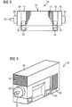
- FIG. 3 schematically shows a side view of the rotary electric machine 34 with a stator 10 and a rotatably mounted in an unspecified opening of the stator 10 arranged rotor 32.
- the stator 10 is, as previously with reference to FIG 1 and FIG. 2 explained, trained.
- the rotary electric machine 34 has a base frame 26, which is fixedly connected by means of the feet 50 with a foundation. In the area of the feet 50, furthermore, the stand 10 can be connected to the base frame 26 via the support braces 24 of the torque supports 16. For clarity, this compound is in FIG. 2 not shown, but it is provided in this embodiment that the damper unit 60 between the support beam 24 and the base frame 26 is arranged ( FIG. 5 ).
- the rotary electric machine 34 is arranged in a housing 36 arranged in a perspective schematic representation. From the housing 36 protrudes the end face of the bearing unit 30 and a shaft journal of the rotor 32nd FIG. 4 It can be seen that the housing 36 comprises a Aufsetzkühlung 58, which is connected to an air inlet opening 46 and an air outlet opening 52. Further, a sheet metal cover 54 is provided, which - not shown - provides an air guiding device within the housing 36 for cooling the rotating electric machine 34. Air is drawn in via the air inlet opening 56 by means of a fan, not shown, of the top cooling 58 and guided for cooling by the rotating electrical machine 34. After the air has passed the rotary electric machine 34, it leaves the housing 36 via the air outlet opening 52.
- the housing 36 is designed as a sheet metal housing and serves only to protect the rotating electrical machine 34.
- the housing 36 is thus not mechanically connected to the stator 10, and therefore can not absorb any vibrations of the stator 10. As a result, a low sound emission can be achieved.
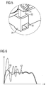
- FIG. 5 shows in an enlarged front view of the area V from FIG. 2 , How out FIG. 5 it can be seen, the support beam 24 is connected via a damping unit 60 with the foot 50 of the base frame 26, so that a support for the stator 10 is formed.
- the damping unit 60 is connected by means not shown fastening means with both the foot 50 and the support beam 24.
- the compound is presently formed by a screw connection. In addition, it can also be formed by gluing, riveting and / or the like.
- FIG. 6 shows in a graphical diagram how the damping unit 60 with respect to the function of the rotary electric machine 34.
- On the ordinate a deflection in the area of the Sitzraverse 24 is normalized.
- the abscissa represents a time axis.
- the rotary electric machine 34 is turned on.
- a graph 62 in the diagram of FIG. 6 represents a waveform in which no damping unit, but only a rigid connection between the support beam 24 and the foot 50 is provided.
- Large deflection which is formed by activation of a resonance of the rotary electric machine 34 in the structure.
- the vibration only stops when the time progresses. This is an essentially undamped or weakly damped process. In this embodiment, it is difficult or dangerous to want to achieve a supercritical operating state of the rotating electrical machine 34.
- the damping unit 60 is provided.
- the graph 66 in the diagram of FIG. 6 shows the same process as described above, but this time with a damping unit 60 which is designed as a passive damping system and is formed by a specially shaped element, which uses a damping element with helical-groove technology under the trade name Power Stop TM. It can be seen that the deflection of the support cross member 24 can be significantly reduced, wherein only in an initial region, a small increase in the deflection takes place.
- the passive damping system thus makes it possible to achieve a significant improvement in the operating characteristics of the rotary electric machine 34 in the existing structure.
- FIG. 6 shows in the diagram with the graph 64 the effects. From the diagram of FIG. 6 It can be seen that the deflection can be completely reduced by means of the dielectric actuator. This makes it possible to reliably and safely operate the rotating electric machine 34 over the entire possible speed range, in particular also to achieve the supercritical range.
Landscapes
- Engineering & Computer Science (AREA)
- Power Engineering (AREA)
- Iron Core Of Rotating Electric Machines (AREA)
Description
- Die vorliegende Erfindung betrifft eine rotierende elektrische Maschine mit einem Ständer und einem in einer Öffnung des Ständers drehbar gelagert angeordneten Läufer.
- Gattungsgemäße elektrische Maschinen sowie Ständer hierfür sind dem Grunde nach im Stand der Technik bekannt, also dass es eines gesonderten druckschriftlichen Nachweises nicht bedarf. Bei einer rotierenden elektrischen Maschine ist dem Grunde nach ein Ständer als Stator vorgesehen, der in der Regel eine im Wesentlichen kreisförmige Öffnung zur Aufnahme eines als Rotor ausgebildeten Läufers bereitstellt. In der Öffnung ist der Läufer drehbar gelagert angeordnet, wobei zwischen dem Läufer und dem Ständer ein Luftspalt ausgebildet ist.
- Eine rotierende elektrische Maschine ist eine Vorrichtung, die elektrische Energie in mechanische Energie, insbesondere Bewegungsenergie (Motorbetrieb) und/oder mechanische Energie in eine elektrische Energie (Generatorbetrieb) umformt. Bei der Bewegung handelt es sich in der Regel um eine Drehbewegung, die vom Läufer ausgeführt wird. Der Ständer ist im Unterschied zum Läufer drehfest angeordnet, das heißt, bei der Drehbewegung handelt es sich um eine Drehbewegung des Läufers gegenüber dem Ständer. Der Ständer und der Läufer sind mittels eines magnetischen Flusses verkettet, wodurch im Motorbetrieb die Kraftwirkung, nämlich das Drehmoment erzeugt wird, die den Läufer gegenüber dem Ständer drehend antreibt, und im Generatorbetrieb dem Läufer zugeführte mechanische Energie in Form einer Rotation in elektrische Energie umwandelt. Zu diesem Zweck weisen der Ständer und der Läufer jeweils eine von einem Strom durchflossene Wicklung auf. Im Ständer oder im Läufer kann die Wicklung auch durch einen Permanentmagneten gebildet oder ergänzt sein.
- Rotierende elektrische Maschinen der gattungsgemäßen Art sind beispielsweise Drehfeldmaschinen, die an ein mehrphasiges, insbesondere dreiphasiges elektrisches Netz angeschlossen sind, wie beispielsweise Asynchronmaschinen, Synchronmaschinen, Synchronmaschinen mit Dämpferkäfig, oder dergleichen.
- Rotierende elektrische Maschinen weisen in der Regel ein Gehäuse auf. Bei großen rotierenden elektrischen Maschinen wird häufig ein Blechpaket des Ständers in das Gehäuse geschrumpft. Über den Schrumpfsitz kann das erzeugte Drehmoment in eine Tragstruktur, ein Fundament oder dergleichen eingeleitet werden, und die Maschine abgestützt werden. Häufig sind die Gehäuse der rotierenden elektrischen Maschinen durch Stahlkonstruktionen gebildet, die aus einzelnen Teilen zusammengeschweißt sind. Aufgrund des Dehnungsverhaltens von Stahl ist der Schrumpfsitz vergleichsweise unproblematisch, weshalb sich diese Art von Gehäuse im praktischen Gebrauch bewährt hat.
- Es hat sich jedoch gezeigt, dass der Aufwand für solche Gehäuse recht hoch ist. Um diesen Aufwand, insbesondere Kosten, reduzieren zu können, gibt es Bestrebungen, die aufwändigen Gehäusekonstruktionen durch Gusskonstruktionen zu ersetzen. Aus Kostengründen wird dabei Grauguss bevorzugt.
- In Bezug auf die rotierende elektrische Maschine erweist sich aber das Dehnungsverhalten aufgrund von Temperatureinwirkung von Grauguss als ungünstig. Grundsätzlich ist Grauguss nur bedingt geeignet, Zugspannungen, die infolge von Schrumpfsitzen in der Struktur entstehen, zu übertragen. Deshalb ist es bei Anwendung von Grauguss erforderlich, die Gehäusekonstruktionen aufwändig zu versteifen, wodurch ein großer Teil einer möglichen Einsparung verloren geht. Weitere Hindernisse entstehen bei der Verwendung von Grauguss durch Einschränkungen bezüglich der Kühlung der rotierenden elektrischen Maschine, insbesondere hinsichtlich der Belüftungsquerschnitte.
- Die
EP 2 045 896 A1 offenbart eine dynamoelektrische Maschine. - Die
GB 669,078 - Die Erfindung hat es sich zur Aufgabe gemacht, den Aufwand für Gehäuse zu reduzieren und zugleich die aus der Verwendung von Grauguss bekannten Nachteile weitgehend zu vermeiden.
- Als Lösung wird mit der Erfindung eine rotierende elektrische Maschine nach Anspruch 1 vorgeschlagen. Ein Ständer dieser rotierenden elektrischen Maschine weist ein Blechpaket in Form eines aus einem ferromagnetischen Werkstoff hergestellten und damit magnetisierbaren, schichtweise aufgebauten Körpers, zwei Druckringe und zwei Drehmomentstützen auf, wobei jeweils ein Druckring mit jeweils einem der gegenüberliegenden stirnseitigen Enden des Blechpakets stoffschlüssig verbunden ist, wobei an jedem der Druckringe jeweils eine der Drehmomentstützen befestigt ist, sodass das Blechpaket mit den Druckringen mittels der Drehmomentstützen direkt gestützt ist und auf den Ständer einwirkende Kräfte und Momente über die Drehmomentstützen vollständig ableitbar sind, so daß mittels der Drehmomentstützen das Blechpaket festlegbar ist.
- Gegenüber den bekannten Gehäusekonstruktionen des Stands der Technik kommt die erfindungsgemäße Ausgestaltung mit wesentlich weniger, insbesondere weniger komplexen Bauteilen aus. Die Drehmomentstütze ist an beiden Stirnseiten des Blechpakets angeordnet und kann gleich ausgeführt sein. Die Stirnseiten des Blechpakets beziehungsweise dessen stirnseitigen Enden sind insbesondere Begrenzungen in axialer Erstreckung des Blechpakets. Axial ist die Richtung einer Drehachse des im Ständer drehbar angeordneten Läufers. Darüber hinaus kann die Drehmomentstütze kostengünstig aus Grauguss gebildet sein, weil Grauguss im Unterschied zu Zugspannungen Druckspannungen gut übertragen kann.
- Die Erfindung nutzt somit die Eigensteifigkeit des Blechpaketes aus und kann deshalb auf ein geschlossenes Gehäuse komplett verzichten. Bedarfsweise kann ergänzend eine dünnwandige Schutzabdeckung vorgesehen sein, die als einfache Blechkonstruktion kostengünstig herstellbar ist. Dadurch ergibt sich zudem eine Gewichtseinsparung, weil ein Gehäuse, beispielsweise in Form einer kostengünstigen Blechkonstruktion, keine großen Kräfte mehr übertragen muss.
- Vollständig ableitbar bedeutet, dass sowohl das Gewicht des Ständers als auch im bestimmungsgemäßen Betrieb einwirkende Momente, insbesondere Drehmomente im Wesentlichen ausschließlich über die Drehmomentstützen abgeleitet werden. Weitere separate Einrichtungen zur Kraft- und/oder Drehmomentübertragung, wie zum Beispiel kraftübertragende Gehäuse, Halterungen und/oder dergleichen, können eingespart werden. Insbesondere erlaubt es die Erfindung, tragende Gehäusevorrichtungen sowie hiermit verbundene aufwändige Verbindungsverfahren wie Schrumpfpressen oder dergleichen zu vermeiden. Das Gewicht des Ständers sowie einwirkende Momente werden vorzugsweise ausschließlich mittels der Drehmomentstütze abgeleitet. Die Drehmomentstützen stützen das Blechpaket mit den Druckringen somit direkt.
- Im Unterschied zum Stand der Technik ist bei der Erfindung der Ständer über das Blechpaket lediglich an seinen stirnseitigen Enden abgestützt. Dazwischen ist keine weitere Abstützung mehr erforderlich, wodurch insbesondere Kontakt mit weiteren Außenteilen weitgehend vermieden werden kann. Dies führt zu einem weiteren Vorteil in Bezug auf Schallemission, weil der Ständer in dem Bereich zwischen den Stirnseiten in der Regel stark schwingt und diese Schwingungen bei Kontakt mit Außenteilen Schall erzeugen können. Die Erfindung erlaubt es also zugleich, eine Reduktion der Schallimmission zu erreichen.
- Der Ständer weist ein Blechpaket auf, das seinerseits aus einzelnen, untereinander elektrisch isolierten ferromagnetischen Blechen besteht. Die Bleche können je nach Verwendungszweck auch als Dynamoblech, Motorenblech, Transformatorenblech oder dergleichen bezeichnet sein. Derartige Bleche unterliegen der Normung, beispielsweise EN10106, EN10107 oder dergleichen. In das Blechpaket eingelassen sind stromführende Wicklungen, die einen magnetischen Fluss bereitstellen. Die Wicklung des Ständers ist somit häufig in das Blechpaket integriert ausgeführt. Der Ständer nimmt die Reaktio in Bezug auf ein Läuferdrehmoment auf und stützt sich gegen eine Auflage ab, um drehfest angeordnet zu sein. Die Abstützung kann durch ein Fundament oder dergleichen Auflage gebildet sein. Das Blechpaket bezeichnet also einen aus ferromagnetischen Werkstoffen hergestellten und damit magnetisierbaren, schichtweise aufgebauten Körper. Die Aufgabe des Blechpakets besteht darin, in Verbindung mit den stromdurchflossenen Wicklungen den magnetischen Fluss zu bündeln.
- An den stirnseitigen Enden des Blechpakets sind jeweils die beiden Drehmomentstützen befestigt. Mittels der Drehmomentstützen ist das Blechpaket festlegbar, das heißt, das Drehmoment in Form der Reaktio kann über die Drehmomentstütze abgeleitet werden. Dadurch ist das Blechpaket und infolgedessen der Ständer drehfest angeordnet im Unterschied zum Läufer.
- Die Befestigung der Drehmomentstützen stirnseitig an den Enden des Blechpakets erfolgt über Druckringe, wobei jeweils einer an einer der stirnseitigen Enden des Blechpakets angeordnet ist. Über die Druckringe wird eine zuverlässige, vorzugsweise lösbare, Ankopplung der Drehmomentstützen an das Blechpaket erreicht. Dies ist vorteilhaft, wenn die rotierende elektrische Maschine, insbesondere der Ständer, zu Wartungszwecken, Reparatur oder dergleichen demontiert werden muss.
- Die Druckringe selbst sind mit dem Blechpaket stoffschlüssig verbunden, das heißt, zwischen dem Druckring und dem Blechpaket besteht eine im Wesentlichen nicht lösbare Verbindung. Diese kann zum Beispiel Löten, Verkleben und/oder dergleichen vorgesehen sein. Der Druckring erlaubt es, eine zuverlässige mechanische Ankopplung des Blechpakets an die Drehmomentstütze während des bestimmungsgemäßen Betriebs des Ständers in der rotierenden elektrischen Maschine zu gewährleisten. Beispielsweise kann Einsatz des Druckrings unterschiedliches Ausdehnungsverhalten, Korrosion auslösende elektrochemische Vorgänge und/oder dergleichen anpassen beziehungsweise vermeiden helfen.
- Besonders vorteilhaft ist die stoffschlüssige Verbindung mittels Schweißen gebildet. Dadurch kann eine besonders zuverlässige und hoch belastbare Verbindung erreicht werden.
- Die Drehmomentstütze selbst kann aus Metall, insbesondere kostengünstig aus Grauguss hergestellt sein. Zwischen den Drehmomentstützen ist das Blechpaket von außen frei zugänglich, sofern nicht weitere Einrichtungen in diesem Bereich für den vorgesehenen bestimmungsgemäßen Betrieb der rotierenden elektrischen Maschine, wie beispielsweise Kühlkanäle oder dergleichen, dort angeordnet sind. Die weitgehend freie Zugänglichkeit des Blechpakets von außen erlaubt es, eine kostengünstige effiziente Kühlung vorzusehen. Dadurch kann die Leistungsfähigkeit der rotierenden elektrischen Maschine erhöht werden. Vorteilhaft ist diese Anordnung an beiden stirnseitigen Enden des Ständerblechpakets identisch ausgeführt.
- Vorteilhaft kann mittels des Druckrings erreicht werden, dass ein Drehmoment vom Ständer mittels Flächenpressung zwischen dem Druckring und der Drehmomentstütze auf diese übertragen werden kann. Die Flächenpressung kann beispielsweise dadurch erzeugt werden, dass der Druckring mit der Drehmomentstütze axial verschraubt ist. Dabei ist die Anzahl der Schrauben vorzugsweise derart gewählt, dass die Flächenpressung ausreicht, um im ungünstigsten Lastfall zum Beispiel das Kurzschlussmoment des Motors zu übertragen. Vorteilhaft ist diese Anordnung an beiden stirnseitigen Enden des Blechpakets des Ständers identisch ausgeführt.
- Eine weitere Ausgestaltung sieht vor, dass die Drehmomentstütze eine Stütztraverse aufweist. Die Stütztraverse ist vorzugsweise einstückig mit der Drehmomentstütze verbunden und kann beispielsweise durch einen radial nach außen ragenden Vorsprung gebildet sein. Die Stütztraverse kann aber auch als separates Bauteil ausgebildet sein, das mit der Drehmomentstütze verbunden ist, beispielsweise mittels Verschraubung, Vernietung, Verschweißung, Verklebung und/oder dergleichen. Über die Stütztraverse kann die Drehmomentstütze zum Beispiel an einem Rahmen befestigt sein, der vorzugsweise mit einem Fundament oder einer vergleichbare Auflage verbunden ist. Vorteilhaft sind wenigstens drei vorzugsweise jedoch vier Stütztraversen vorgesehen, wobei die Stütztraversen einen gegenüberliegenden Umfangspositionen der Drehmomentstützen angeordnet sind. Dadurch lässt sich eine zuverlässige, stabile Fixierung des Ständers, insbesondere des Blechpakets erreichen.
- Gemäß einer weiteren Ausgestaltung der Erfindung ist vorgesehen, dass die Drehmomentstütze eine Lagervorrichtung für einen Läufer der rotierenden elektrischen Maschine aufweist. Die Lagervorrichtung kann zum Beispiel durch einen Lagerschild gebildet sein, der mit der Drehmomentstütze verbunden ist, insbesondere einstückig mit ihr ausgebildet ist. Der Lagerschild kann eine Lagereinheit aufweisen, die eine Welle des in der Öffnung des Ständers angeordneten Läufers drehbar lagert.
- Gemäß einer weiteren Ausgestaltung wird vorgeschlagen, dass die Stütztraverse eine Dämpfungseinheit aufweist. Mittels der Dämpfungseinheit kann erreicht werden, dass rotierende elektrische Maschinen, die bislang nicht für einen Betrieb im überkritischen Bereich geeignet sind, überkritisch betrieben werden können. Daneben können aufbau- und/oder maschinenbedingte Resonanzen eingestellt und/oder gedämpft werden sowie eine Schallerzeugung reduziert werden. So können beispielsweise Kosten eingespart werden, indem teure Gleitlager durch kostengünstige Wälzlager bei der Lagerung des Läufers vorgesehen sein können. Weitere Vorteile ergeben sich dadurch, dass Kosten durch reduzierte Anforderungen an die Genauigkeit bei Fertigungsprozessen eingespart werden können, eine höhere Sicherheit erreicht werden kann und Sperrbereiche hinsichtlich Drehzahlen im bestimmungsgemäßen Betrieb, insbesondere bei Drehzahlregelungen, reduziert werden oder entfallen können.
- Die Dämpfungseinheit kann als passives Dämpfungssystem oder auch als aktives Dämpfungssystem ausgestaltet sein. Ein passives Dämpfungssystem kann zu diesem Zweck elastisch und/oder plastisch verformbare Elemente aufweisen, beispielsweise Gummidämpfer, Federelemente und/oder dergleichen. Darüber hinaus können die verformbaren Elemente weitere mechanische Maßnahmen aufweisen wie zum Beispiel Nuten und oder dergleichen, mit denen ihre Eigenschaften eingestellt werden können. Insbesondere kann diesbezüglich eine Wedel-Nut-Technologie zum Einsatz kommen. Vorzugsweise ist das passive Dämpfungssystem derart ausgelegt, dass ein weitgehend ungestörtes Durchfahren von Resonanzstellen erreicht werden kann.
- Besonders vorteilhaft kann die Dämpfungseinheit einen Aktuator aufweisen. Mittels des Aktuators kann eine aktive Dämpfung einer Resonanzstelle beziehungsweise Resonanzschwingung erreicht werden. Zu dem Zweck wird der Aktuator mittels eines Regelungssystem geeignet angesteuert. Der Aktuator kann beispielsweise ein den piezoelektrischen Effekt nutzender Aktuator, zum Beispiel in Stapelbauweise oder dergleichen sein.
- Mit der Erfindung wird eine rotierende elektrische Maschine der gattungsgemäßen Art vorgeschlagen, wobei der Ständer wie zuvor ausgeführt ausgebildet ist. Dadurch kann die rotierende elektrische Maschine einfacher und kostengünstiger ausgebildet sein. Weiterhin kann eine Schallreduktion und eine verbesserte Kühlung erreicht werden.
- Die Erfindung sieht vor, dass die rotierende elektrische Maschine ein vom Blechpaket des Ständers beabstandetes Gehäuse aufweist. Dadurch kann ein Schutz der elektrischen Maschine vor äußeren Einwirkungen erreicht werden. Zugleich erlaubt es die erfindungsgemäße Konstruktion, ein einfaches Gehäuse mit wenig komplexen Bauteilen auszubilden. Das Gehäuse muss bei der Erfindung nämlich keine Drehmomente übertragen und auch keine thermische Ankopplung realisieren. Dadurch kann das Gehäuse kostengünstig aus Blech hergestellt sein. Natürlich erlaubt es die Erfindung, auch Gehäuse aus Werkstoffen wie Kunststoff, Verbundwerkstoffen, beispielsweise faserverstärkten Kunststoffen oder dergleichen zu nutzen.
- Darüber hinaus kann mit der Erfindung das aufwändige Fügen von Ständer und Gehäuse weitgehend vermieden werden, weil eine Verbindung von Gehäuse und Ständer nicht mehr erforderlich ist. Infolgedessen ist auch eine Fertigung von Ständer beziehungsweise Ständerbauteilen und Gehäuse mit seinen Bauteilen nicht mehr an die für das Fügen erforderlichen engen Toleranzen gebunden. Dadurch kann Aufwand, insbesondere können Kosten eingespart werden.
- Das Gehäuse bildet demnach lediglich noch eine dünnwandige Schutzabdeckung, woraus sich ergänzend eine Gewichtseinsparung ergibt.
- Um die Schallunterdrückung weiter zu verbessern, ist vorgesehen, dass zwischen dem Blechpaket und dem Gehäuse ein schalldämmendes Material angeordnet ist. Dies kann beispielsweise als eigene Schicht mit dem Gehäuse verbunden sein. Das schalldämmende Material selbst kann durch einen porigen Werkstoff gebildet sein, beispielsweise einen Schaumstoff, insbesondere einen offenporigen Schaumstoff, einen Faserstoff, beispielsweise Mineralfaser, Steinwolle oder dergleichen, oder Kombinationen hiervon. Zwischen dem Blechpaket und dem Gehäuse beziehungsweise dem schalldämmenden Material kann ferner ein Luftspalt vorgesehen sein, der ein Durchströmen eines Kühlmediums wie zum Beispiel Luft oder dergleichen erlaubt.
- Vorteilhaft umfasst die rotierende elektrische Maschine einen mit einer Stütztraverse einer Drehmomentstütze verbindbaren Grundrahmen. Der Grundrahmen kann an die Drehmomentstützen adaptiert ausgebildet sein, sodass eine zuverlässige und einfach herzustellende Verbindung mit einem Fundament, oder einer dergleichen Auflage realisiert werden kann. Besonders vorteilhaft kann die Drehmomenteinleitung in unmittelbarer Nähe eines Fußes am Grundrahmen erfolgen, wodurch sich ein sehr günstiger Kraftfluss ergibt. Dadurch kann ferner die Möglichkeit eröffnet werden, die Wandstärke des Grundrahmens im Bereich zwischen den Füßen zu minimieren. Daraus ergeben sich weitere Gewichts- und Kostenvorteile. Der Grundrahmen ist vorzugsweise Bestandteil der rotierenden elektrischen Maschine.
- Eine weitere Ausgestaltung sieht vor, dass zwischen der Stütztraverse und dem Grundrahmen eine Dämpfereinheit angeordnet ist. Die Dämpfereinheit kann beispielsweise durch ein elastisches Bauelement gebildet sein, beispielsweise einem Gummipuffer, einem elastischen Kunststoffelement und/oder dergleichen. Dadurch lässt sich eine weitere Entkopplung der rotierenden elektrischen Maschine von der Auflage erreichen.
- Ferner kann vorgesehen sein, dass das Gehäuse eine Kühlvorrichtung aufweist. Die Kühlvorrichtung kann beispielsweise eine auf einem Medium wie Luft, Wasser oder dergleichen basierende Kühlvorrichtung sein. Besonders vorteilhaft erweist sich eine Luftkühlvorrichtung, zu welchem Zweck das Gehäuse einen Ventilator aufweist, der über eine Einlassöffnung Kühlluft ansaugt und zur rotierenden elektrischen Maschine, beispielsweise dem Blechpaket, dem Läufer und/oder dergleichen führt. Über eine Austrittsöffnung im Gehäuse kann die erwärmte Luft wieder abgeführt werden.
- Insbesondere bei großen rotierenden elektrischen Maschinen, die auf große Leistung und/oder große Drehzahl ausgelegt sind, werden hohe Anforderungen an die Dynamik gestellt. Beispielsweise ist der Läufer schlank ausgeführt, das heißt, mit kleinem Durchmesser bei großer Paketlänge. Dadurch ergibt sich, dass zum Erreichen einer Betriebsdrehzahl aus dem Stand heraus eine oder mehrere Biegeschwingungen beziehungsweise sich daraus ergebende Resonanzen durchfahren werden müssen. Es ist angestrebt, solche Resonanzstellen schnell zu durchfahren, und gezielt Dämpfungseffekte zu nutzen, um eine Resonanzüberhöhung möglichst gering zu halten. Ohne derartige Dämpfungen können solche Bereiche nicht sicher durchfahren werden, beziehungsweise ein überkritischer Betrieb der rotierenden elektrischen Maschine kann nicht erreicht werden. Der überkritische Betrieb ist bei der rotierenden elektrischen Maschine ein Betriebszustand mit einer Drehzahl oberhalb einer Eigenschwingung und demzufolge einer Resonanz.
- Gemäß einer weiteren Ausgestaltung ist deshalb bei der rotierenden elektrischen Maschine zwischen der Stütztraverse und dem Grundrahmen eine Dämpfungseinheit angeordnet. Vorzugsweise ist die Dämpfungseinheit in die rotierende elektrische Maschine integriert angeordnet, sodass Montageaufwand bei der Aufstellung der rotierenden elektrischen Maschine reduziert werden kann.
- In einer Weiterbildung weist die Dämpfungseinheit einen Aktuator auf. Dadurch kann eine hoch effektive Dämpfung von Resonanzen erreicht werden.
- Weitere Merkmale und Vorteile sind der folgenden Beschreibung eines Ausführungsbeispiels zu entnehmen. Die Beschreibung dient lediglich zur Erläuterung der Erfindung und soll diese nicht beschränken.
- Es zeigen:
- FIG 1
- eine schematische Schnittdarstellung eines Ausschnitts eines Blechpakets eines Ständers verbunden mit einer Drehmomentstütze gemäß der Erfindung,
- FIG 2
- eine perspektivische schematische Darstellung einer rotierenden elektrischen Maschine mit einer Festlegung gemäß der Erfindung,
- FIG 3
- eine schematische Darstellung in einer rotierenden elektrischen Maschine mit einer Festlegung des Ständers gemäß der Erfindung in einer Seitenansicht,
- FIG 4
- eine perspektivische Ansicht der Maschine gemäß
FIG 3 angeordnet in einem Gehäuse, - FIG 5
- in schematisch Frontansicht ein vergrößerter Ausschnitt V aus
FIG 2 , und - FIG 6
- ein Auslenkung-Zeit-Diagramm, welches eine Schwingungsauslenkung an einer Stütztraverse einer Drehmomentstütze gemäß
FIG 1 und 2 über der Zeit bei unterschiedlichen Dämpfungseinheiten darstellt. -
FIG 1 zeigt in schematischer Schnittdarstellung einen Ausschnitt eines Ständers 10 einer rotierenden elektrischen Maschine 34 mit einem Blechpaket 12, an dessen stirnseitigen Enden 14 jeweils eine Drehmomentstütze 16 befestigt ist, mittels der das Blechpaket 12 festlegbar ist. Über die Drehmomentstützen 16 ist das Blechpaket 12 somit drehfest angeordnet, sodass es die Reaktio in Wechselwirkung mit dem im Ständer 10 angeordneten Läufer 32 ableiten kann. - Aus
FIG 1 ist ferner ersichtlich, dass zwischen dem Blechpaket 12 und der Drehmomentstütze 16 ein Druckring 18 angeordnet ist. Der Druckring 18 ist über eine Verschweißung 22 mit dem Blechpaket 12 verbunden. Der Druckring 18 stellt darüber hinaus Gewindebohrungen 40 bereit, die in geeigneter Anzahl über den äußeren Umfang des Druckrings 18 in axialer Richtung der rotierenden elektrischen Maschine 34 angeordnet sind. Die Drehmomentstütze 16 weist entsprechende Bohrungen auf, sodass mittels Verschraubungen 20 eine lösbare Verbindung der Drehmomentstütze 16 mit dem Druckring 18 gebildet werden kann. - Der Druckring 18 weist ferner einen umlaufenden Absatz 46 auf, der mit einer stirnseitig in der Drehmomentstütze 16 eingebrachten umlaufenden Ausnehmung 48 korrespondiert. Dadurch wird eine Zentrierung 44 gebildet.
- Die Anzahl der Verschraubungen 22 ist derart gewählt, dass die Flächenpressung ausreicht, um im ungünstigsten Lastfall auch das Kurzschlussmoment der rotierenden elektrischen Maschine 34 übertragen zu können. Die in
FIG 1 dargestellte Anordnung ist an beiden Enden des Blechpakets 12 des Ständers 10 identisch ausgeführt. -
FIG 2 zeigt in perspektivischer schematischer Darstellung den Ständer 10 angeordnet oberhalb eines Grundrahmens 26, der mit einem nicht näher dargestellten Fundament fest verbunden ist. Zu diesem Zweck weist der Grundrahmen 26 einen etwa rechteckförmigen Grundquerschnitt auf, in dessen Eckpunkten Füße 50 angeordnet sind. Ferner ist ausFIG 2 ersichtlich, dass die Drehmomentstützen 16 Stütztraversen 24 aufweisen, die gegenüberliegend in Umfangsrichtung an den Drehmomentstützen 16 angeordnet sind. Über nicht dargestellte Befestigungen mit Dämpfereinheiten 60 ist der Ständer 10 mit dem Grundrahmen 26 im Bereich der Füße 50 über die Stütztraversen 24 verbunden. - Ferner ist aus
FIG 2 ersichtlich, dass die Drehmomentstütze 16 einstückig mit einem Lagerschild 28 versehen ist. Der Lagerschild 28 weist eine Lagereinheit 30 auf (FIG 3 ), mittels der ein Läufer 32 in einer nicht dargestellten Öffnung des Ständers 10 drehbar gelagert angeordnet ist. -
FIG 3 zeigt schematisch eine Seitenansicht der rotierenden elektrischen Maschine 34 mit einem Ständer 10 und einem in einer nicht bezeichneten Öffnung des Ständers 10 drehbar gelagert angeordneten Läufer 32. Der Ständer 10 ist, wie zuvor anhand derFIG 1 und FIG 2 erläutert, ausgebildet. - Die rotierende elektrische Maschine 34 weist einen Grundrahmen 26 auf, der mittels der Füße 50 mit einem Fundament fest verbunden ist. Im Bereich der Füße 50 ist ferner der Ständer 10 über die Stütztraversen 24 der Drehmomentstützen 16 mit dem Grundrahmen 26 verbindbar. Aus Gründen der Übersichtlichkeit ist diese Verbindung in
FIG 2 nicht dargestellt, jedoch ist in dieser Ausgestaltung vorgesehen, dass die Dämpfereinheit 60 zwischen der Stütztraverse 24 und dem Grundrahmen 26 angeordnet ist (FIG 5 ). - In
FIG 4 ist die rotierende elektrische Maschine 34 in einem Gehäuse 36 angeordnet in perspektivischer schematischer Darstellung dargestellt. Aus dem Gehäuse 36 ragt stirnseitig die Lagereinheit 30 sowie ein Wellenzapfen des Läufers 32. AusFIG 4 ist ersichtlich, dass das Gehäuse 36 eine Aufsetzkühlung 58 umfasst, die mit einer Lufteintrittsöffnung 46 und einer Luftaustrittsöffnung 52 verbunden ist. Ferner ist eine Blechabdeckung 54 vorgesehen, die - nicht dargestellt - eine Luftleitvorrichtung innerhalb des Gehäuses 36 zur Kühlung der rotierenden elektrischen Maschine 34 bereitstellt. Über die Lufteintrittsöffnung 56 wird mittels eines nicht dargestellten Lüfters der Aufsatzkühlung 58 Luft angesaugt und zur Kühlung durch die rotierende elektrische Maschine 34 geführt. Nachdem die Luft die rotierende elektrische Maschine 34 passiert hat, verlässt sie das Gehäuse 36 über die Luftaustrittsöffnung 52. - Das Gehäuse 36 ist als Blechgehäuse ausgebildet und dient lediglich dem Schutz der rotierenden elektrischen Maschine 34. Das Gehäuse 36 ist somit nicht mit dem Ständer 10 mechanisch verbunden, und kann deshalb auch keine Schwingungen des Ständers 10 aufnehmen. Dadurch kann eine geringe Schallaussendung erreicht werden.
-
FIG 5 zeigt in vergrößerter Frontansicht den Bereich V ausFIG 2 . Wie ausFIG 5 ersichtlich ist, ist die Stütztraverse 24 über eine Dämpfungseinheit 60 mit dem Fuß 50 des Grundrahmens 26 verbunden, sodass eine Auflage für den Ständer 10 gebildet ist. Die Dämpfungseinheit 60 ist mittels nicht dargestellter Befestigungsmittel sowohl mit dem Fuß 50 als auch mit der Stütztraverse 24 verbunden. Die Verbindung ist vorliegend durch eine Schraubverbindung gebildet. Daneben kann sie aber auch durch Kleben, Nieten und/oder dergleichen gebildet sein. - Als Schwingungsdämpfungseinheit 60 kann sowohl ein passives Dämpfungssystem basierend auf einem elastisch und/oder plastisch verformbaren Werkstoff oder auch ein aktives Dämpfungssystem basierend auf einem steuerbaren Aktuator, beispielsweise einen piezo-elektrischen Aktuator und/oder dergleichen oder Kombinationen hiervon aufweisen.
-
FIG 6 zeigt in einem grafischen Diagramm, wie sich die Dämpfungseinheit 60 bezüglich der Funktion der rotierenden elektrischen Maschine 34 auswirkt. Auf der Ordinate ist normiert eine Auslenkung im Bereich der Sütztraverse 24 aufgetragen. Die Abszisse stellt eine Zeitachse dar. Im Ursprung wird die rotierende elektrische Maschine 34 eingeschaltet. - Ein Graph 62 im Diagramm der
FIG 6 stellt einen Schwingungsverlauf dar, bei dem keine Dämpfungseinheit, sondern lediglich eine starre Verbindung zwischen der Stütztraverse 24 und dem Fuß 50 vorgesehen ist. Zu erkennen ist große Auslenkung, die durch Aktivierung einer Resonanz der rotierenden elektrischen Maschine 34 in dem Aufbau gebildet ist. Die Schwingung klingt erst mit weiter Fortschreitung der Zeit ab. Es handelt sich hierbei um einen im Wesentlichen ungedämpften beziehungsweise schwach gedämpften Vorgang. In dieser Ausgestaltung ist es schwierig beziehungsweise gefährlich, einen überkritischen Betriebszustand der rotierenden elektrischen Maschine 34 erreichen zu wollen. - Um hier eine Verbesserung erreichen zu können, ist die Dämpfungseinheit 60 vorgesehen. Der Graph 66 im Diagramm der
FIG 6 zeigt den gleichen, wie zuvor beschriebenen Vorgang, jedoch diesmal mit einer Dämpfungseinheit 60, das als passives Dämpfungssystem ausgelegt ist und durch ein speziell geformtes Element gebildet ist, das unter der Handelsbezeichnung Power Stop™ ein Dämpfungselement mit Wendel-Nut-Technologie nutzt. Zu erkennen ist, dass die Auslenkung der Stütztraverse 24 deutlich reduziert werden kann, wobei lediglich in einem Anfangsbereich eine kleine Überhöhung der Auslenkung erfolgt. Das passive Dämpfungssystem erlaubt es somit, eine deutliche Verbesserung hinsichtlich der Betriebseigenschaften der rotierenden elektrischen Maschine 34 im bestehenden Aufbau erreichen zu können. - Eine weitere Verbesserung ergibt sich, wenn als Dämpfungseinheit 60 ein dielektrischer Aktuator, in Form eines Hochvolt-Stapelaktuators zum Einsatz kommt.
FIG 6 zeigt in dem Diagramm mit dem Graph 64 die Auswirkungen. Aus dem Diagramm derFIG 6 ist zu entnehmen, dass mittels des dielektrischen Aktuators die Auslenkung vollständig reduziert werden kann. Dadurch ist es möglich, die rotierende elektrische Maschine 34 über den gesamten möglichen Drehzahlbereich zuverlässig und sicher zu betreiben, insbesondere auch den überkritischen Bereich zu erreichen.
Claims (11)
- Rotierende elektrische Maschine (34) mit einem Ständer (10) und einem in einer Öffnung des Ständers (10) drehbar gelagert angeordneten Läufer (32), wobei der Ständer (10) ein Blechpaket (12) in Form eines aus einem ferromagnetischen Werkstoff hergestellten und damit magnetisierbaren, schichtweise aufgebauten Körpers, zwei Druckringe (18) und zwei Drehmomentstützen (16) aufweist, wobei jeweils ein Druckring (18) mit jeweils einem der gegenüberliegenden stirnseitigen Enden des Blechpakets (12) stoffschlüssig verbunden ist, wobei an jedem der Druckringe (18) jeweils eine der Drehmomentstützen (16) befestigt ist, so dass das Blechpaket (12) mit den Druckringen (18) mittels der Drehmomentstützen (16) direkt gestützt ist und auf den Ständer (10) einwirkende Kräfte und Momente über die Drehmomentstützen (16) vollständig ableitbar sind, so dass mittels der Drehmomentstützen (16) das Blechpaket (12) festlegbar ist,
gekennzeichnet durch
ein vom Blechpaket (12) des Ständers (10) beabstandetes Gehäuse (36), wobei zwischen dem Blechpaket (12) und dem Gehäuse (36) ein schalldämmendes Material angeordnet ist. - Rotierende elektrische Maschine nach Anspruch 1,
dadurch gekennzeichnet, dass das Gehäuse (36) eine Kühlvorrichtung (38) aufweist. - Rotierende elektrische Maschine nach einem der Ansprüche 1 oder 2, gekennzeichnet durch einen mit einer Stütztraverse (24) einer Drehmomentstütze (16) verbindbaren Grundrahmen (26).
- Rotierende elektrische Maschine nach Anspruch 3,
dadurch gekennzeichnet, dass zwischen der Stütztraverse (24) und dem Grundrahmen (26) eine Dämpfungseinheit (60) angeordnet ist. - Rotierende elektrische Maschine nach Anspruch 4,
dadurch gekennzeichnet, dass die Dämpfungseinheit (60) einen Aktuator aufweist. - Rotierende elektrische Maschine nach einem der Ansprüche 1 bis 5, dadurch gekennzeichnet, dass der Druckring (18) über Flächenpressung mit der Drehmomentstütze (16) drehfest verbunden ist.
- Rotierende elektrische Maschine nach einem der Ansprüche 1 bis 6, dadurch gekennzeichnet, dass die stoffschlüssige Verbindung durch Schweißen gebildet ist.
- Rotierende elektrische Maschine nach einem der Ansprüche 1 bis 7, dadurch gekennzeichnet, dass die Drehmomentstütze (16) eine Lagervorrichtung (28, 30) für einen Läufer der rotierenden elektrischen Maschine (34) aufweist.
- Rotierende elektrische Maschine nach einem der Ansprüche 1 bis 8, dadurch gekennzeichnet, dass die Drehmomentstütze (16) eine Stütztraverse (24) aufweist.
- Rotierende elektrische Maschine nach Anspruch 9,
dadurch gekennzeichnet, dass die Stütztraverse (24) eine Dämpfungseinheit (60) aufweist. - Rotierende elektrische Maschine nach Anspruch 10,
dadurch gekennzeichnet, dass die Dämpfungseinheit (60) einen Aktuator aufweist.
Priority Applications (1)
| Application Number | Priority Date | Filing Date | Title |
|---|---|---|---|
| EP13164083.1A EP2793361B1 (de) | 2013-04-17 | 2013-04-17 | Rotierende elektrische Maschine |
Applications Claiming Priority (1)
| Application Number | Priority Date | Filing Date | Title |
|---|---|---|---|
| EP13164083.1A EP2793361B1 (de) | 2013-04-17 | 2013-04-17 | Rotierende elektrische Maschine |
Publications (2)
| Publication Number | Publication Date |
|---|---|
| EP2793361A1 EP2793361A1 (de) | 2014-10-22 |
| EP2793361B1 true EP2793361B1 (de) | 2017-08-30 |
Family
ID=48128169
Family Applications (1)
| Application Number | Title | Priority Date | Filing Date |
|---|---|---|---|
| EP13164083.1A Not-in-force EP2793361B1 (de) | 2013-04-17 | 2013-04-17 | Rotierende elektrische Maschine |
Country Status (1)
| Country | Link |
|---|---|
| EP (1) | EP2793361B1 (de) |
Families Citing this family (3)
| Publication number | Priority date | Publication date | Assignee | Title |
|---|---|---|---|---|
| FR3030617B1 (fr) * | 2014-12-12 | 2019-07-19 | Valeo Systemes De Controle Moteur | Machine electrique |
| FR3036885B1 (fr) * | 2015-05-27 | 2018-11-09 | Valeo Equipements Electriques Moteur | Machine electrique tournante munie d'un berceau et d'un stator coaxiaux |
| FR3082674B1 (fr) * | 2018-06-15 | 2021-06-04 | Ge Energy Power Conversion Technology Ltd | Carcasse pour machine electrique tournante, stator et procede d'insertion d'un stator dans une telle carcasse |
Family Cites Families (3)
| Publication number | Priority date | Publication date | Assignee | Title |
|---|---|---|---|---|
| GB669078A (en) * | 1948-10-27 | 1952-03-26 | Gen Motors Corp | Improved stator for dynamo electric machines and methods of making the same |
| US3988622A (en) * | 1972-12-11 | 1976-10-26 | Bbc Brown Boveri & Company Limited | Dynamo-electric machine with prestressed laminated stator component |
| US8134272B2 (en) * | 2006-07-26 | 2012-03-13 | Mitsubishi Electric Corporation | Dynamoelectric machine |
-
2013
- 2013-04-17 EP EP13164083.1A patent/EP2793361B1/de not_active Not-in-force
Non-Patent Citations (1)
| Title |
|---|
| None * |
Also Published As
| Publication number | Publication date |
|---|---|
| EP2793361A1 (de) | 2014-10-22 |
Similar Documents
| Publication | Publication Date | Title |
|---|---|---|
| EP3360239B1 (de) | Umformmaschine, insbesondere schmiedehammer | |
| DE102018100562A1 (de) | Motorisiertes antriebssystem, verwendung des antriebssystems zur betätigung einer tür, herstellungsverfahren für ein antriebssystem | |
| EP2923436A2 (de) | Stator mit einer umspritzung und elektrische maschine mit dem stator | |
| DE102009017865A1 (de) | Generatoranordnung für Windenergieanlage | |
| EP2850719B1 (de) | Statoranordnung für eine elektrische maschine | |
| WO2007128742A1 (de) | Elektrische maschine, insbesondere permanenterregter synchronmotor mit einstellbarer feldschwächung | |
| DE102009017850A1 (de) | Läufer für eine elektrische Maschine | |
| WO2015120914A1 (de) | Elektrische maschine mit rahmen und hülle | |
| EP3099930B1 (de) | Windenergieanlage | |
| EP2793361A1 (de) | Rotierende elektrische Maschine | |
| EP3308449B1 (de) | Statorring für einen elektrischen generator, sowie generator und windenergieanlage mit selbigem | |
| WO2024240298A1 (de) | Rotor | |
| DE102008005294B3 (de) | Verstellbarer Federträger | |
| EP3002856A1 (de) | Greif- oder schwenkeinheit | |
| EP2976826B1 (de) | Rotierende elektrische maschine | |
| DE102014115924A1 (de) | Türantrieb | |
| EP4256199B1 (de) | Generator-getriebe-anordnung mit bremse für eine windkraftanlage | |
| EP2295621B1 (de) | Friktions-Motorspindel | |
| DE102006049327A1 (de) | Rollenantriebssystem mit Schwingungsdämpfung | |
| DE102011103493A1 (de) | Elektrische Maschine mit zwei Statoreinheiten und zwei Rotoreinheiten | |
| EP3106379A1 (de) | Schiffsantrieb mit körperschallentkopplung | |
| EP2793371A1 (de) | Rotierende elektrische Maschine | |
| EP2149971B1 (de) | Drehlinearantriebsvorrichtung mit läuferstabilisierendem, weichmagnetischem Element | |
| WO2023186854A1 (de) | Elektrische maschine | |
| EP3130062B1 (de) | Gegossenes gehäuse mit einem versteifungselement |
Legal Events
| Date | Code | Title | Description |
|---|---|---|---|
| PUAI | Public reference made under article 153(3) epc to a published international application that has entered the european phase |
Free format text: ORIGINAL CODE: 0009012 |
|
| 17P | Request for examination filed |
Effective date: 20130417 |
|
| AK | Designated contracting states |
Kind code of ref document: A1 Designated state(s): AL AT BE BG CH CY CZ DE DK EE ES FI FR GB GR HR HU IE IS IT LI LT LU LV MC MK MT NL NO PL PT RO RS SE SI SK SM TR |
|
| AX | Request for extension of the european patent |
Extension state: BA ME |
|
| R17P | Request for examination filed (corrected) |
Effective date: 20141106 |
|
| RBV | Designated contracting states (corrected) |
Designated state(s): AL AT BE BG CH CY CZ DE DK EE ES FI FR GB GR HR HU IE IS IT LI LT LU LV MC MK MT NL NO PL PT RO RS SE SI SK SM TR |
|
| GRAP | Despatch of communication of intention to grant a patent |
Free format text: ORIGINAL CODE: EPIDOSNIGR1 |
|
| RIC1 | Information provided on ipc code assigned before grant |
Ipc: H02K 5/24 20060101ALN20170308BHEP Ipc: H02K 1/18 20060101AFI20170308BHEP |
|
| INTG | Intention to grant announced |
Effective date: 20170324 |
|
| GRAS | Grant fee paid |
Free format text: ORIGINAL CODE: EPIDOSNIGR3 |
|
| GRAA | (expected) grant |
Free format text: ORIGINAL CODE: 0009210 |
|
| AK | Designated contracting states |
Kind code of ref document: B1 Designated state(s): AL AT BE BG CH CY CZ DE DK EE ES FI FR GB GR HR HU IE IS IT LI LT LU LV MC MK MT NL NO PL PT RO RS SE SI SK SM TR |
|
| RAP1 | Party data changed (applicant data changed or rights of an application transferred) |
Owner name: SIEMENS AKTIENGESELLSCHAFT |
|
| REG | Reference to a national code |
Ref country code: GB Ref legal event code: FG4D Free format text: NOT ENGLISH |
|
| REG | Reference to a national code |
Ref country code: CH Ref legal event code: EP |
|
| REG | Reference to a national code |
Ref country code: AT Ref legal event code: REF Ref document number: 924506 Country of ref document: AT Kind code of ref document: T Effective date: 20170915 |
|
| REG | Reference to a national code |
Ref country code: IE Ref legal event code: FG4D Free format text: LANGUAGE OF EP DOCUMENT: GERMAN |
|
| REG | Reference to a national code |
Ref country code: CH Ref legal event code: NV Representative=s name: SIEMENS SCHWEIZ AG, CH Ref country code: CH Ref legal event code: PCOW Free format text: NEW ADDRESS: WERNER-VON-SIEMENS-STRASSE 1, 80333 MUENCHEN (DE) |
|
| REG | Reference to a national code |
Ref country code: DE Ref legal event code: R096 Ref document number: 502013008175 Country of ref document: DE |
|
| REG | Reference to a national code |
Ref country code: NL Ref legal event code: MP Effective date: 20170830 |
|
| REG | Reference to a national code |
Ref country code: LT Ref legal event code: MG4D |
|
| PG25 | Lapsed in a contracting state [announced via postgrant information from national office to epo] |
Ref country code: LT Free format text: LAPSE BECAUSE OF FAILURE TO SUBMIT A TRANSLATION OF THE DESCRIPTION OR TO PAY THE FEE WITHIN THE PRESCRIBED TIME-LIMIT Effective date: 20170830 Ref country code: SE Free format text: LAPSE BECAUSE OF FAILURE TO SUBMIT A TRANSLATION OF THE DESCRIPTION OR TO PAY THE FEE WITHIN THE PRESCRIBED TIME-LIMIT Effective date: 20170830 Ref country code: NO Free format text: LAPSE BECAUSE OF FAILURE TO SUBMIT A TRANSLATION OF THE DESCRIPTION OR TO PAY THE FEE WITHIN THE PRESCRIBED TIME-LIMIT Effective date: 20171130 Ref country code: HR Free format text: LAPSE BECAUSE OF FAILURE TO SUBMIT A TRANSLATION OF THE DESCRIPTION OR TO PAY THE FEE WITHIN THE PRESCRIBED TIME-LIMIT Effective date: 20170830 |
|
| PG25 | Lapsed in a contracting state [announced via postgrant information from national office to epo] |
Ref country code: IS Free format text: LAPSE BECAUSE OF FAILURE TO SUBMIT A TRANSLATION OF THE DESCRIPTION OR TO PAY THE FEE WITHIN THE PRESCRIBED TIME-LIMIT Effective date: 20171230 Ref country code: BG Free format text: LAPSE BECAUSE OF FAILURE TO SUBMIT A TRANSLATION OF THE DESCRIPTION OR TO PAY THE FEE WITHIN THE PRESCRIBED TIME-LIMIT Effective date: 20171130 Ref country code: ES Free format text: LAPSE BECAUSE OF FAILURE TO SUBMIT A TRANSLATION OF THE DESCRIPTION OR TO PAY THE FEE WITHIN THE PRESCRIBED TIME-LIMIT Effective date: 20170830 Ref country code: RS Free format text: LAPSE BECAUSE OF FAILURE TO SUBMIT A TRANSLATION OF THE DESCRIPTION OR TO PAY THE FEE WITHIN THE PRESCRIBED TIME-LIMIT Effective date: 20170830 Ref country code: GR Free format text: LAPSE BECAUSE OF FAILURE TO SUBMIT A TRANSLATION OF THE DESCRIPTION OR TO PAY THE FEE WITHIN THE PRESCRIBED TIME-LIMIT Effective date: 20171201 Ref country code: LV Free format text: LAPSE BECAUSE OF FAILURE TO SUBMIT A TRANSLATION OF THE DESCRIPTION OR TO PAY THE FEE WITHIN THE PRESCRIBED TIME-LIMIT Effective date: 20170830 |
|
| PG25 | Lapsed in a contracting state [announced via postgrant information from national office to epo] |
Ref country code: NL Free format text: LAPSE BECAUSE OF FAILURE TO SUBMIT A TRANSLATION OF THE DESCRIPTION OR TO PAY THE FEE WITHIN THE PRESCRIBED TIME-LIMIT Effective date: 20170830 |
|
| PG25 | Lapsed in a contracting state [announced via postgrant information from national office to epo] |
Ref country code: DK Free format text: LAPSE BECAUSE OF FAILURE TO SUBMIT A TRANSLATION OF THE DESCRIPTION OR TO PAY THE FEE WITHIN THE PRESCRIBED TIME-LIMIT Effective date: 20170830 Ref country code: CZ Free format text: LAPSE BECAUSE OF FAILURE TO SUBMIT A TRANSLATION OF THE DESCRIPTION OR TO PAY THE FEE WITHIN THE PRESCRIBED TIME-LIMIT Effective date: 20170830 Ref country code: PL Free format text: LAPSE BECAUSE OF FAILURE TO SUBMIT A TRANSLATION OF THE DESCRIPTION OR TO PAY THE FEE WITHIN THE PRESCRIBED TIME-LIMIT Effective date: 20170830 Ref country code: RO Free format text: LAPSE BECAUSE OF FAILURE TO SUBMIT A TRANSLATION OF THE DESCRIPTION OR TO PAY THE FEE WITHIN THE PRESCRIBED TIME-LIMIT Effective date: 20170830 |
|
| PG25 | Lapsed in a contracting state [announced via postgrant information from national office to epo] |
Ref country code: SK Free format text: LAPSE BECAUSE OF FAILURE TO SUBMIT A TRANSLATION OF THE DESCRIPTION OR TO PAY THE FEE WITHIN THE PRESCRIBED TIME-LIMIT Effective date: 20170830 Ref country code: EE Free format text: LAPSE BECAUSE OF FAILURE TO SUBMIT A TRANSLATION OF THE DESCRIPTION OR TO PAY THE FEE WITHIN THE PRESCRIBED TIME-LIMIT Effective date: 20170830 Ref country code: SM Free format text: LAPSE BECAUSE OF FAILURE TO SUBMIT A TRANSLATION OF THE DESCRIPTION OR TO PAY THE FEE WITHIN THE PRESCRIBED TIME-LIMIT Effective date: 20170830 |
|
| REG | Reference to a national code |
Ref country code: DE Ref legal event code: R097 Ref document number: 502013008175 Country of ref document: DE |
|
| PLBE | No opposition filed within time limit |
Free format text: ORIGINAL CODE: 0009261 |
|
| STAA | Information on the status of an ep patent application or granted ep patent |
Free format text: STATUS: NO OPPOSITION FILED WITHIN TIME LIMIT |
|
| 26N | No opposition filed |
Effective date: 20180531 |
|
| PG25 | Lapsed in a contracting state [announced via postgrant information from national office to epo] |
Ref country code: SI Free format text: LAPSE BECAUSE OF FAILURE TO SUBMIT A TRANSLATION OF THE DESCRIPTION OR TO PAY THE FEE WITHIN THE PRESCRIBED TIME-LIMIT Effective date: 20170830 |
|
| PG25 | Lapsed in a contracting state [announced via postgrant information from national office to epo] |
Ref country code: MT Free format text: LAPSE BECAUSE OF FAILURE TO SUBMIT A TRANSLATION OF THE DESCRIPTION OR TO PAY THE FEE WITHIN THE PRESCRIBED TIME-LIMIT Effective date: 20170830 |
|
| REG | Reference to a national code |
Ref country code: DE Ref legal event code: R119 Ref document number: 502013008175 Country of ref document: DE |
|
| PG25 | Lapsed in a contracting state [announced via postgrant information from national office to epo] |
Ref country code: MC Free format text: LAPSE BECAUSE OF FAILURE TO SUBMIT A TRANSLATION OF THE DESCRIPTION OR TO PAY THE FEE WITHIN THE PRESCRIBED TIME-LIMIT Effective date: 20170830 |
|
| REG | Reference to a national code |
Ref country code: CH Ref legal event code: PL |
|
| REG | Reference to a national code |
Ref country code: BE Ref legal event code: MM Effective date: 20180430 |
|
| GBPC | Gb: european patent ceased through non-payment of renewal fee |
Effective date: 20180417 |
|
| REG | Reference to a national code |
Ref country code: IE Ref legal event code: MM4A |
|
| PG25 | Lapsed in a contracting state [announced via postgrant information from national office to epo] |
Ref country code: DE Free format text: LAPSE BECAUSE OF NON-PAYMENT OF DUE FEES Effective date: 20181101 Ref country code: LU Free format text: LAPSE BECAUSE OF NON-PAYMENT OF DUE FEES Effective date: 20180417 Ref country code: FI Free format text: LAPSE BECAUSE OF NON-PAYMENT OF DUE FEES Effective date: 20180417 |
|
| PG25 | Lapsed in a contracting state [announced via postgrant information from national office to epo] |
Ref country code: BE Free format text: LAPSE BECAUSE OF NON-PAYMENT OF DUE FEES Effective date: 20180430 Ref country code: GB Free format text: LAPSE BECAUSE OF NON-PAYMENT OF DUE FEES Effective date: 20180417 Ref country code: CH Free format text: LAPSE BECAUSE OF NON-PAYMENT OF DUE FEES Effective date: 20180430 Ref country code: LI Free format text: LAPSE BECAUSE OF NON-PAYMENT OF DUE FEES Effective date: 20180430 |
|
| PG25 | Lapsed in a contracting state [announced via postgrant information from national office to epo] |
Ref country code: FR Free format text: LAPSE BECAUSE OF NON-PAYMENT OF DUE FEES Effective date: 20180430 Ref country code: IT Free format text: LAPSE BECAUSE OF NON-PAYMENT OF DUE FEES Effective date: 20180417 Ref country code: IE Free format text: LAPSE BECAUSE OF NON-PAYMENT OF DUE FEES Effective date: 20180417 |
|
| REG | Reference to a national code |
Ref country code: AT Ref legal event code: MM01 Ref document number: 924506 Country of ref document: AT Kind code of ref document: T Effective date: 20180417 |
|
| PG25 | Lapsed in a contracting state [announced via postgrant information from national office to epo] |
Ref country code: AT Free format text: LAPSE BECAUSE OF NON-PAYMENT OF DUE FEES Effective date: 20180417 |
|
| PG25 | Lapsed in a contracting state [announced via postgrant information from national office to epo] |
Ref country code: TR Free format text: LAPSE BECAUSE OF FAILURE TO SUBMIT A TRANSLATION OF THE DESCRIPTION OR TO PAY THE FEE WITHIN THE PRESCRIBED TIME-LIMIT Effective date: 20170830 |
|
| PG25 | Lapsed in a contracting state [announced via postgrant information from national office to epo] |
Ref country code: PT Free format text: LAPSE BECAUSE OF FAILURE TO SUBMIT A TRANSLATION OF THE DESCRIPTION OR TO PAY THE FEE WITHIN THE PRESCRIBED TIME-LIMIT Effective date: 20170830 Ref country code: HU Free format text: LAPSE BECAUSE OF FAILURE TO SUBMIT A TRANSLATION OF THE DESCRIPTION OR TO PAY THE FEE WITHIN THE PRESCRIBED TIME-LIMIT; INVALID AB INITIO Effective date: 20130417 |
|
| PG25 | Lapsed in a contracting state [announced via postgrant information from national office to epo] |
Ref country code: MK Free format text: LAPSE BECAUSE OF NON-PAYMENT OF DUE FEES Effective date: 20170830 Ref country code: CY Free format text: LAPSE BECAUSE OF FAILURE TO SUBMIT A TRANSLATION OF THE DESCRIPTION OR TO PAY THE FEE WITHIN THE PRESCRIBED TIME-LIMIT Effective date: 20170830 |
|
| PG25 | Lapsed in a contracting state [announced via postgrant information from national office to epo] |
Ref country code: AL Free format text: LAPSE BECAUSE OF FAILURE TO SUBMIT A TRANSLATION OF THE DESCRIPTION OR TO PAY THE FEE WITHIN THE PRESCRIBED TIME-LIMIT Effective date: 20170830 |