EP2792767A1 - Film forming device and manufacturing method for glass with film - Google Patents
Film forming device and manufacturing method for glass with film Download PDFInfo
- Publication number
- EP2792767A1 EP2792767A1 EP12857902.6A EP12857902A EP2792767A1 EP 2792767 A1 EP2792767 A1 EP 2792767A1 EP 12857902 A EP12857902 A EP 12857902A EP 2792767 A1 EP2792767 A1 EP 2792767A1
- Authority
- EP
- European Patent Office
- Prior art keywords
- film
- glass
- cylindrical body
- forming device
- glass film
- Prior art date
- Legal status (The legal status is an assumption and is not a legal conclusion. Google has not performed a legal analysis and makes no representation as to the accuracy of the status listed.)
- Granted
Links
Images

Classifications
-
- C—CHEMISTRY; METALLURGY
- C03—GLASS; MINERAL OR SLAG WOOL
- C03C—CHEMICAL COMPOSITION OF GLASSES, GLAZES OR VITREOUS ENAMELS; SURFACE TREATMENT OF GLASS; SURFACE TREATMENT OF FIBRES OR FILAMENTS MADE FROM GLASS, MINERALS OR SLAGS; JOINING GLASS TO GLASS OR OTHER MATERIALS
- C03C17/00—Surface treatment of glass, not in the form of fibres or filaments, by coating
- C03C17/001—General methods for coating; Devices therefor
- C03C17/002—General methods for coating; Devices therefor for flat glass, e.g. float glass
-
- C—CHEMISTRY; METALLURGY
- C03—GLASS; MINERAL OR SLAG WOOL
- C03C—CHEMICAL COMPOSITION OF GLASSES, GLAZES OR VITREOUS ENAMELS; SURFACE TREATMENT OF GLASS; SURFACE TREATMENT OF FIBRES OR FILAMENTS MADE FROM GLASS, MINERALS OR SLAGS; JOINING GLASS TO GLASS OR OTHER MATERIALS
- C03C17/00—Surface treatment of glass, not in the form of fibres or filaments, by coating
- C03C17/06—Surface treatment of glass, not in the form of fibres or filaments, by coating with metals
- C03C17/09—Surface treatment of glass, not in the form of fibres or filaments, by coating with metals by deposition from the vapour phase
-
- C—CHEMISTRY; METALLURGY
- C03—GLASS; MINERAL OR SLAG WOOL
- C03C—CHEMICAL COMPOSITION OF GLASSES, GLAZES OR VITREOUS ENAMELS; SURFACE TREATMENT OF GLASS; SURFACE TREATMENT OF FIBRES OR FILAMENTS MADE FROM GLASS, MINERALS OR SLAGS; JOINING GLASS TO GLASS OR OTHER MATERIALS
- C03C17/00—Surface treatment of glass, not in the form of fibres or filaments, by coating
- C03C17/22—Surface treatment of glass, not in the form of fibres or filaments, by coating with other inorganic material
- C03C17/23—Oxides
- C03C17/245—Oxides by deposition from the vapour phase
-
- C—CHEMISTRY; METALLURGY
- C23—COATING METALLIC MATERIAL; COATING MATERIAL WITH METALLIC MATERIAL; CHEMICAL SURFACE TREATMENT; DIFFUSION TREATMENT OF METALLIC MATERIAL; COATING BY VACUUM EVAPORATION, BY SPUTTERING, BY ION IMPLANTATION OR BY CHEMICAL VAPOUR DEPOSITION, IN GENERAL; INHIBITING CORROSION OF METALLIC MATERIAL OR INCRUSTATION IN GENERAL
- C23C—COATING METALLIC MATERIAL; COATING MATERIAL WITH METALLIC MATERIAL; SURFACE TREATMENT OF METALLIC MATERIAL BY DIFFUSION INTO THE SURFACE, BY CHEMICAL CONVERSION OR SUBSTITUTION; COATING BY VACUUM EVAPORATION, BY SPUTTERING, BY ION IMPLANTATION OR BY CHEMICAL VAPOUR DEPOSITION, IN GENERAL
- C23C14/00—Coating by vacuum evaporation, by sputtering or by ion implantation of the coating forming material
- C23C14/0021—Reactive sputtering or evaporation
- C23C14/0036—Reactive sputtering
-
- C—CHEMISTRY; METALLURGY
- C23—COATING METALLIC MATERIAL; COATING MATERIAL WITH METALLIC MATERIAL; CHEMICAL SURFACE TREATMENT; DIFFUSION TREATMENT OF METALLIC MATERIAL; COATING BY VACUUM EVAPORATION, BY SPUTTERING, BY ION IMPLANTATION OR BY CHEMICAL VAPOUR DEPOSITION, IN GENERAL; INHIBITING CORROSION OF METALLIC MATERIAL OR INCRUSTATION IN GENERAL
- C23C—COATING METALLIC MATERIAL; COATING MATERIAL WITH METALLIC MATERIAL; SURFACE TREATMENT OF METALLIC MATERIAL BY DIFFUSION INTO THE SURFACE, BY CHEMICAL CONVERSION OR SUBSTITUTION; COATING BY VACUUM EVAPORATION, BY SPUTTERING, BY ION IMPLANTATION OR BY CHEMICAL VAPOUR DEPOSITION, IN GENERAL
- C23C14/00—Coating by vacuum evaporation, by sputtering or by ion implantation of the coating forming material
- C23C14/22—Coating by vacuum evaporation, by sputtering or by ion implantation of the coating forming material characterised by the process of coating
- C23C14/54—Controlling or regulating the coating process
- C23C14/541—Heating or cooling of the substrates
-
- C—CHEMISTRY; METALLURGY
- C23—COATING METALLIC MATERIAL; COATING MATERIAL WITH METALLIC MATERIAL; CHEMICAL SURFACE TREATMENT; DIFFUSION TREATMENT OF METALLIC MATERIAL; COATING BY VACUUM EVAPORATION, BY SPUTTERING, BY ION IMPLANTATION OR BY CHEMICAL VAPOUR DEPOSITION, IN GENERAL; INHIBITING CORROSION OF METALLIC MATERIAL OR INCRUSTATION IN GENERAL
- C23C—COATING METALLIC MATERIAL; COATING MATERIAL WITH METALLIC MATERIAL; SURFACE TREATMENT OF METALLIC MATERIAL BY DIFFUSION INTO THE SURFACE, BY CHEMICAL CONVERSION OR SUBSTITUTION; COATING BY VACUUM EVAPORATION, BY SPUTTERING, BY ION IMPLANTATION OR BY CHEMICAL VAPOUR DEPOSITION, IN GENERAL
- C23C14/00—Coating by vacuum evaporation, by sputtering or by ion implantation of the coating forming material
- C23C14/22—Coating by vacuum evaporation, by sputtering or by ion implantation of the coating forming material characterised by the process of coating
- C23C14/56—Apparatus specially adapted for continuous coating; Arrangements for maintaining the vacuum, e.g. vacuum locks
- C23C14/562—Apparatus specially adapted for continuous coating; Arrangements for maintaining the vacuum, e.g. vacuum locks for coating elongated substrates
-
- C—CHEMISTRY; METALLURGY
- C23—COATING METALLIC MATERIAL; COATING MATERIAL WITH METALLIC MATERIAL; CHEMICAL SURFACE TREATMENT; DIFFUSION TREATMENT OF METALLIC MATERIAL; COATING BY VACUUM EVAPORATION, BY SPUTTERING, BY ION IMPLANTATION OR BY CHEMICAL VAPOUR DEPOSITION, IN GENERAL; INHIBITING CORROSION OF METALLIC MATERIAL OR INCRUSTATION IN GENERAL
- C23C—COATING METALLIC MATERIAL; COATING MATERIAL WITH METALLIC MATERIAL; SURFACE TREATMENT OF METALLIC MATERIAL BY DIFFUSION INTO THE SURFACE, BY CHEMICAL CONVERSION OR SUBSTITUTION; COATING BY VACUUM EVAPORATION, BY SPUTTERING, BY ION IMPLANTATION OR BY CHEMICAL VAPOUR DEPOSITION, IN GENERAL
- C23C16/00—Chemical coating by decomposition of gaseous compounds, without leaving reaction products of surface material in the coating, i.e. chemical vapour deposition [CVD] processes
- C23C16/44—Chemical coating by decomposition of gaseous compounds, without leaving reaction products of surface material in the coating, i.e. chemical vapour deposition [CVD] processes characterised by the method of coating
- C23C16/46—Chemical coating by decomposition of gaseous compounds, without leaving reaction products of surface material in the coating, i.e. chemical vapour deposition [CVD] processes characterised by the method of coating characterised by the method used for heating the substrate
-
- C—CHEMISTRY; METALLURGY
- C23—COATING METALLIC MATERIAL; COATING MATERIAL WITH METALLIC MATERIAL; CHEMICAL SURFACE TREATMENT; DIFFUSION TREATMENT OF METALLIC MATERIAL; COATING BY VACUUM EVAPORATION, BY SPUTTERING, BY ION IMPLANTATION OR BY CHEMICAL VAPOUR DEPOSITION, IN GENERAL; INHIBITING CORROSION OF METALLIC MATERIAL OR INCRUSTATION IN GENERAL
- C23C—COATING METALLIC MATERIAL; COATING MATERIAL WITH METALLIC MATERIAL; SURFACE TREATMENT OF METALLIC MATERIAL BY DIFFUSION INTO THE SURFACE, BY CHEMICAL CONVERSION OR SUBSTITUTION; COATING BY VACUUM EVAPORATION, BY SPUTTERING, BY ION IMPLANTATION OR BY CHEMICAL VAPOUR DEPOSITION, IN GENERAL
- C23C16/00—Chemical coating by decomposition of gaseous compounds, without leaving reaction products of surface material in the coating, i.e. chemical vapour deposition [CVD] processes
- C23C16/44—Chemical coating by decomposition of gaseous compounds, without leaving reaction products of surface material in the coating, i.e. chemical vapour deposition [CVD] processes characterised by the method of coating
- C23C16/54—Apparatus specially adapted for continuous coating
- C23C16/545—Apparatus specially adapted for continuous coating for coating elongated substrates
-
- C—CHEMISTRY; METALLURGY
- C03—GLASS; MINERAL OR SLAG WOOL
- C03C—CHEMICAL COMPOSITION OF GLASSES, GLAZES OR VITREOUS ENAMELS; SURFACE TREATMENT OF GLASS; SURFACE TREATMENT OF FIBRES OR FILAMENTS MADE FROM GLASS, MINERALS OR SLAGS; JOINING GLASS TO GLASS OR OTHER MATERIALS
- C03C2217/00—Coatings on glass
- C03C2217/20—Materials for coating a single layer on glass
- C03C2217/21—Oxides
-
- C—CHEMISTRY; METALLURGY
- C03—GLASS; MINERAL OR SLAG WOOL
- C03C—CHEMICAL COMPOSITION OF GLASSES, GLAZES OR VITREOUS ENAMELS; SURFACE TREATMENT OF GLASS; SURFACE TREATMENT OF FIBRES OR FILAMENTS MADE FROM GLASS, MINERALS OR SLAGS; JOINING GLASS TO GLASS OR OTHER MATERIALS
- C03C2217/00—Coatings on glass
- C03C2217/20—Materials for coating a single layer on glass
- C03C2217/25—Metals
-
- C—CHEMISTRY; METALLURGY
- C03—GLASS; MINERAL OR SLAG WOOL
- C03C—CHEMICAL COMPOSITION OF GLASSES, GLAZES OR VITREOUS ENAMELS; SURFACE TREATMENT OF GLASS; SURFACE TREATMENT OF FIBRES OR FILAMENTS MADE FROM GLASS, MINERALS OR SLAGS; JOINING GLASS TO GLASS OR OTHER MATERIALS
- C03C2217/00—Coatings on glass
- C03C2217/90—Other aspects of coatings
- C03C2217/94—Transparent conductive oxide layers [TCO] being part of a multilayer coating
- C03C2217/948—Layers comprising indium tin oxide [ITO]
-
- C—CHEMISTRY; METALLURGY
- C03—GLASS; MINERAL OR SLAG WOOL
- C03C—CHEMICAL COMPOSITION OF GLASSES, GLAZES OR VITREOUS ENAMELS; SURFACE TREATMENT OF GLASS; SURFACE TREATMENT OF FIBRES OR FILAMENTS MADE FROM GLASS, MINERALS OR SLAGS; JOINING GLASS TO GLASS OR OTHER MATERIALS
- C03C2218/00—Methods for coating glass
- C03C2218/10—Deposition methods
- C03C2218/15—Deposition methods from the vapour phase
- C03C2218/152—Deposition methods from the vapour phase by cvd
-
- C—CHEMISTRY; METALLURGY
- C03—GLASS; MINERAL OR SLAG WOOL
- C03C—CHEMICAL COMPOSITION OF GLASSES, GLAZES OR VITREOUS ENAMELS; SURFACE TREATMENT OF GLASS; SURFACE TREATMENT OF FIBRES OR FILAMENTS MADE FROM GLASS, MINERALS OR SLAGS; JOINING GLASS TO GLASS OR OTHER MATERIALS
- C03C2218/00—Methods for coating glass
- C03C2218/10—Deposition methods
- C03C2218/15—Deposition methods from the vapour phase
- C03C2218/154—Deposition methods from the vapour phase by sputtering
Definitions
- This invention relates to a film forming device and a method for manufacturing a film-coated glass film using the device.
- Patent Literature 1 describes a method in which a glass sheet fed from a substrate roll is heated with a can heated to 300°C or above and an ITO (indium-tin oxide) film is formed on a surface of the heated glass sheet on the can by sputtering.
- ITO indium-tin oxide
- Patent Literature 1 JP-A-2007-119322
- Patent Literature 1 metal is used as a material of the can.
- metal is used as a material of the can.
- the film forming device is increased in size and the cost for film formation rises.
- the surface of the metallic can is more likely to be oxidized.
- An object of the present invention is to provide a device capable of suitably forming a film on a glass film.
- a film forming device includes a heating roll and a film forming unit.
- the heating roll has a surface onto which a glass film is to be fed.
- the heating roll is configured to heat the glass film.
- the film forming unit is configured to form a film on the glass film.
- the heating roll includes a cylindrical body and a heater.
- the cylindrical body is made of glass or ceramic.
- the cylindrical body is rotatably provided.
- the heater is disposed in an interior of the cylindrical body. The heater is configured to heat the cylindrical body.
- the cylindrical body is preferably made of at least one selected from the group consisting of quartz glass, crystallized glass, alumina, silica, silicon nitride, and silicon carbide.
- the film forming device preferably further includes a feed unit located between the cylindrical body and the glass film and configured to feed a sheet whose surface layer next to the glass film has a lower hardness than the glass film.
- the sheet is preferably made of metal.
- the sheet preferably has one to ten times the coefficient of thermal expansion of the glass film.
- the heater may be disposed to heat a portion of the cylindrical body coming into contact with the glass film.
- the heater is preferably configured to emit heat rays toward the cylindrical body.
- the film forming device according to the present invention preferably further includes an absorbing layer disposed on an inner peripheral surface of the cylindrical body and capable of absorbing heat rays emitted from the heater.
- the film forming unit may be constituted by a reactive gas supply unit configured to supply a reactive gas capable of thermally reacting on the glass film to form a film thereon or a sputtering unit configured to deposit sputtered particles on the glass film.
- a film is formed on the glass film using the film forming device according to the present invention.
- the film may be formed by thermal CVD or sputtering.
- a device capable of suitably forming a film on a glass film can be provided.
- Fig. 1 is a schematic side view of a film forming device 1 in this embodiment.
- the film forming device 1 is a device for forming a film 11 (see Fig. 3 ) on a surface 10a of a flexible glass film 10 to produce a film-coated glass film 12 including the glass film 10 and the film 11.
- the thickness of the glass film 10 is, for example, preferably not greater than 300 ⁇ m, more preferably not greater than 100 ⁇ m, and still more preferably not greater than 50 ⁇ m.
- the glass film 10 may be made of, for example, silicate glass, borate glass or phosphate glass.
- examples of the glass film include a crystallized glass film made of crystallized glass.
- the film 11 may be made of an oxide, such as tin oxide, indium oxide, silicon oxide, titanium oxide, niobium oxide, tantalum oxide or lanthanum oxide; a nitride, such as silicon nitride or titanium nitride; or a metal, such as silicon, silver, copper or aluminum.
- oxide such as tin oxide, indium oxide, silicon oxide, titanium oxide, niobium oxide, tantalum oxide or lanthanum oxide
- a nitride such as silicon nitride or titanium nitride
- a metal such as silicon, silver, copper or aluminum.
- the film forming device 1 includes a heating roll 20.
- the heating roll 20 includes a cylindrical body 21 and a heater 22.
- the cylindrical body 21 is supported rotatably about a central axis C1 by a core 23 held against rotation into the cylindrical body 21.
- the cylindrical body 21 is capable of rotating about the central axis C1 together with the rotation of rotary rolls 25a, 25b.
- the cylindrical body 21 is made of glass or ceramic.
- Specific examples of the glass preferably used as a constituent material of the cylindrical body 21 include quartz glass and crystallized glass.
- Specific examples of the ceramic preferably used as a constituent material of the cylindrical body 21 include alumina, silica, silicon nitride, and silicon carbide.
- the outside diameter of the cylindrical body 21 can be, for example, about 100 mm to about 2000 mm.
- the thickness of the cylindrical body 21 is, for example, preferably about 3 mm to about 20 mm. If the thickness of the cylindrical body 21 is too small, the strength of the cylindrical body 21 may be low. If the thickness of the cylindrical body 21 is too large, the heat capacity of the cylindrical body 21 will be large. This needs to give the cylindrical body 21 large energy for the purpose of heating it or maintaining its temperature and may make it difficult to control the temperature of the glass film.
- the heater 22 is disposed in the interior of the cylindrical body 21. Specifically, the heater 22 is disposed in a cutaway formed in the core 23 to face the inner peripheral surface 21a of the cylindrical body 21. More specifically, the heater 22 is disposed facing a portion of the cylindrical body 21 coming into contact with the glass film 10 and thus configured to heat the portion of the cylindrical body 21 coming into contact with the glass film 10.
- the heater 22 may be formed of, for example, an infrared heater or near-infrared heater configured to emit heat rays toward the cylindrical body 21.
- an absorbing layer 24 capable of absorbing heat rays emitted from the heater 22 is preferably disposed on the inner peripheral surface 21a of the cylindrical body 21.
- the absorbing layer 24 can be made of, for example, a black body paint containing, as a pigment, graphite, iron, manganese or the like.
- a film forming unit 30 is disposed above the cylindrical body 21 opposite to the heater 22 with the cylindrical body 21 in between.
- the film forming unit 30 is configured to form a film 11 on the surface 10a of the glass film 10.
- the film forming unit 30 can be appropriately constituted according to the film forming method.
- the film forming unit 30 in forming a film 11 on the surface 10a of the glass film 10 by thermal CVD (chemical vapor deposition), the film forming unit 30 can be constituted by a reactive gas supply unit configured to supply a reactive gas capable of thermally reacting on the glass film 10 to form a film 11 thereon.
- the film forming unit 30 in forming a film 11 on the surface 10a of the glass film 10 by sputtering, can be constituted by a sputtering unit configured to deposit sputtered particles on the glass film 10.
- the film forming device 1 is provided with a glass film feed roll 40 and a take-up roll 41.
- the glass film feed roll 40 is configured to feed a yet-to-be-coated glass film 10 onto the outer peripheral surface 21b of the cylindrical body 21.
- the take-up roll 41 is configured to take up a film-coated glass film 12 which includes the glass film 10 and a film 11 formed on the surface 10a of the glass film 10.
- the film forming device 1 is further provided with a sheet feed roll 42 and a sheet take-up roll 43.
- the sheet feed roll 42 is configured to feed a buffer film 44 to between the outer peripheral surface 21b of the cylindrical body 21 and the glass film 10.
- the sheet take-up roll 43 is configured to take up the buffer film 44 discharged from between the outer peripheral surface 21b of the cylindrical body 21 and the glass film 10.
- the buffer film 44 is formed of a sheet whose surface layer next to the glass film 10 has a lower hardness than the glass film 10.
- the buffer film 44 can be made of, for example, at least one metal of aluminum, iron, copper, and so on. In other words, the buffer film 44 can be constituted by a metal film.
- a buffer film 44 is fed to between the high-hardness cylindrical body 21 made of glass or ceramic and the glass film 10. Therefore, it can be effectively prevented that the surface of the glass film 10 is scratched by the contact of the glass film 10 with the cylindrical body 21.
- the buffer film 44 is one capable of reflecting or absorbing heat rays from the heater 22, the heating efficiency of the cylindrical body 21 can be further increased.
- the thickness of the buffer film 44 is, for example, preferably about 10 ⁇ m to about 100 ⁇ m.
- the buffer film 44 preferably has about one to about ten times the coefficient of thermal expansion of the glass film.
- a glass film 10 is fed from the glass film feed roll 40 onto the outer peripheral surface 21b of the cylindrical body 21.
- a buffer film 44 is fed from the sheet feed roll 42 to between the glass film 10 and the outer peripheral surface 21b of the cylindrical body 21.
- the contact between the cylindrical body 21 and the glass film 10 is restricted.
- the cylindrical body 21 With the feeding of the glass film 10 and the buffer film 44, the cylindrical body 21 is driven into rotation by the rotary rolls 25a, 25b. This reduces the friction between the glass film 10 and the buffer film 44 and the friction between the buffer film 44 and the cylindrical body 21.
- the glass film 10 fed onto the outer peripheral surface 21b of the cylindrical body 21 is heated by the heating roll 20.
- the heater 22 heats the cylindrical body 21 and the heated cylindrical body 21 heats the glass film 10 to a temperature suitable for film formation.
- a film 11 is formed on the surface 10a of the heated glass film 10, such as by sputtering or thermal CVD, using the film forming unit 30, resulting in the production of a film-coated glass film 12.
- the produced film-coated glass film 12 is taken up by the take-up roll 41.
- the buffer film 44 is taken up by the take-up roll 43.
- the buffer film 44 may be taken up together with the film-coated glass film 12.
- a film different from the buffer film 44 for example, a film made of paper or resin, may be taken up. This prevents damage to the film-coated glass film 12 caused by the contact between portions of the film-coated glass film 12.
- the outer peripheral surface of the heating roll 20 coming into contact with the glass film 10 is formed by the cylindrical body 21 made of glass or ceramic. Therefore, even if oxygen is present in an atmosphere for film formation, the surface of the heating roll 20 coming into contact with the glass film 10 cannot be oxidized. Hence, the change in the profile of a surface of the glass film 10 next to the heating roll 20 can be reduced. Furthermore, since there is no need to additionally provide any means for reducing the oxidation of the surface of the heating roll 20, the structure of the film forming device 1 can be simplified, resulting in reduced cost for producing a film-coated glass film 12.
Landscapes
- Chemical & Material Sciences (AREA)
- Organic Chemistry (AREA)
- Chemical Kinetics & Catalysis (AREA)
- Engineering & Computer Science (AREA)
- Materials Engineering (AREA)
- Metallurgy (AREA)
- Mechanical Engineering (AREA)
- General Chemical & Material Sciences (AREA)
- Life Sciences & Earth Sciences (AREA)
- Geochemistry & Mineralogy (AREA)
- Surface Treatment Of Glass (AREA)
- Physical Vapour Deposition (AREA)
- Chemical Vapour Deposition (AREA)
Abstract
Description
- This invention relates to a film forming device and a method for manufacturing a film-coated glass film using the device.
- Recently, there are demands to form a film on the top of a flexible glass film. For example,
Patent Literature 1 describes a method in which a glass sheet fed from a substrate roll is heated with a can heated to 300°C or above and an ITO (indium-tin oxide) film is formed on a surface of the heated glass sheet on the can by sputtering. - Patent Literature 1:
JP-A-2007-119322 - However, in the method described in
Patent Literature 1, metal is used as a material of the can. In order to reduce that the surface of the metallic can coming into contact with the glass sheet and heated to a high temperature is oxidized and thereby altered or degraded, it is necessary to form a film with the can placed in an inert gas atmosphere. Hence, the film forming device is increased in size and the cost for film formation rises. Particularly, in the case of applying the film forming device to a thermal CVD device requiring higher temperatures than sputtering, the surface of the metallic can is more likely to be oxidized. - An object of the present invention is to provide a device capable of suitably forming a film on a glass film.
- A film forming device according to the present invention includes a heating roll and a film forming unit. The heating roll has a surface onto which a glass film is to be fed. The heating roll is configured to heat the glass film. The film forming unit is configured to form a film on the glass film. The heating roll includes a cylindrical body and a heater. The cylindrical body is made of glass or ceramic. The cylindrical body is rotatably provided. The heater is disposed in an interior of the cylindrical body. The heater is configured to heat the cylindrical body.
- The cylindrical body is preferably made of at least one selected from the group consisting of quartz glass, crystallized glass, alumina, silica, silicon nitride, and silicon carbide.
- The film forming device according to the present invention preferably further includes a feed unit located between the cylindrical body and the glass film and configured to feed a sheet whose surface layer next to the glass film has a lower hardness than the glass film.
- The sheet is preferably made of metal.
- The sheet preferably has one to ten times the coefficient of thermal expansion of the glass film.
- The heater may be disposed to heat a portion of the cylindrical body coming into contact with the glass film.
- The heater is preferably configured to emit heat rays toward the cylindrical body. In this case, the film forming device according to the present invention preferably further includes an absorbing layer disposed on an inner peripheral surface of the cylindrical body and capable of absorbing heat rays emitted from the heater.
- The film forming unit may be constituted by a reactive gas supply unit configured to supply a reactive gas capable of thermally reacting on the glass film to form a film thereon or a sputtering unit configured to deposit sputtered particles on the glass film.
- In a method for manufacturing a film-coated glass film according to the present invention, a film is formed on the glass film using the film forming device according to the present invention.
- The film may be formed by thermal CVD or sputtering. Advantageous Effects of Invention
- In the present invention, a device capable of suitably forming a film on a glass film can be provided.
-
- [
Fig. 1] Fig. 1 is a schematic side view of a film forming device in one embodiment of the present invention. - [
Fig. 2] Fig. 2 is an enlarged schematic side view of the portion II ofFig. 1 . - [
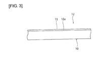
Fig. 3] Fig. 3 is a schematic side view of a film-coated glass film manufactured in the one embodiment of the present invention. - A description will be given below of an example of a preferred embodiment for working of the present invention. However, the following embodiment is simply illustrative. The present invention is not at all limited by the following embodiment.
- The drawings to which the embodiment and the like refer are schematically illustrated, and the dimensional ratios and the like of objects illustrated in the drawings may be different from those of the actual objects. Different drawings may have different dimensional ratios and the like of the objects. Dimensional ratios and the like of specific objects should be determined in consideration of the following description.
-
Fig. 1 is a schematic side view of afilm forming device 1 in this embodiment. Thefilm forming device 1 is a device for forming a film 11 (seeFig. 3 ) on asurface 10a of aflexible glass film 10 to produce a film-coatedglass film 12 including theglass film 10 and thefilm 11. - No particular limitation is placed on the thickness of the
glass film 10 so long as theglass film 10 has flexibility. The thickness of theglass film 10 is, for example, preferably not greater than 300 µm, more preferably not greater than 100 µm, and still more preferably not greater than 50 µm. - No particular limitation is placed on the type of glass forming the
glass film 10. Theglass film 10 may be made of, for example, silicate glass, borate glass or phosphate glass. In the present invention, examples of the glass film include a crystallized glass film made of crystallized glass. - No particular limitation is placed on the type of the
film 11. Thefilm 11 may be made of an oxide, such as tin oxide, indium oxide, silicon oxide, titanium oxide, niobium oxide, tantalum oxide or lanthanum oxide; a nitride, such as silicon nitride or titanium nitride; or a metal, such as silicon, silver, copper or aluminum. - The
film forming device 1 includes aheating roll 20. Theheating roll 20 includes acylindrical body 21 and aheater 22. Thecylindrical body 21 is supported rotatably about a central axis C1 by acore 23 held against rotation into thecylindrical body 21. Thecylindrical body 21 is capable of rotating about the central axis C1 together with the rotation ofrotary rolls - The
cylindrical body 21 is made of glass or ceramic. Specific examples of the glass preferably used as a constituent material of thecylindrical body 21 include quartz glass and crystallized glass. Specific examples of the ceramic preferably used as a constituent material of thecylindrical body 21 include alumina, silica, silicon nitride, and silicon carbide. - No particular limitation is placed on the outside diameter of the
cylindrical body 21. The outside diameter of thecylindrical body 21 can be, for example, about 100 mm to about 2000 mm. The thickness of thecylindrical body 21 is, for example, preferably about 3 mm to about 20 mm. If the thickness of thecylindrical body 21 is too small, the strength of thecylindrical body 21 may be low. If the thickness of thecylindrical body 21 is too large, the heat capacity of thecylindrical body 21 will be large. This needs to give thecylindrical body 21 large energy for the purpose of heating it or maintaining its temperature and may make it difficult to control the temperature of the glass film. - The
heater 22 is disposed in the interior of thecylindrical body 21. Specifically, theheater 22 is disposed in a cutaway formed in the core 23 to face the innerperipheral surface 21a of thecylindrical body 21. More specifically, theheater 22 is disposed facing a portion of thecylindrical body 21 coming into contact with theglass film 10 and thus configured to heat the portion of thecylindrical body 21 coming into contact with theglass film 10. - No particular limitation is placed on the type of the
heater 22 so long as it can heat thecylindrical body 21 to a temperature at which afilm 11 can be formed on thesurface 10a of theglass film 10. Theheater 22 may be formed of, for example, an infrared heater or near-infrared heater configured to emit heat rays toward thecylindrical body 21. In this case, as shown inFig. 2 , an absorbinglayer 24 capable of absorbing heat rays emitted from theheater 22 is preferably disposed on the innerperipheral surface 21a of thecylindrical body 21. Thus, the heating efficiency of thecylindrical body 21 can be increased. - The absorbing
layer 24 can be made of, for example, a black body paint containing, as a pigment, graphite, iron, manganese or the like. - A
film forming unit 30 is disposed above thecylindrical body 21 opposite to theheater 22 with thecylindrical body 21 in between. Thefilm forming unit 30 is configured to form afilm 11 on thesurface 10a of theglass film 10. - The
film forming unit 30 can be appropriately constituted according to the film forming method. For example, in forming afilm 11 on thesurface 10a of theglass film 10 by thermal CVD (chemical vapor deposition), thefilm forming unit 30 can be constituted by a reactive gas supply unit configured to supply a reactive gas capable of thermally reacting on theglass film 10 to form afilm 11 thereon. For another example, in forming afilm 11 on thesurface 10a of theglass film 10 by sputtering, thefilm forming unit 30 can be constituted by a sputtering unit configured to deposit sputtered particles on theglass film 10. - The
film forming device 1 is provided with a glassfilm feed roll 40 and a take-up roll 41. The glassfilm feed roll 40 is configured to feed a yet-to-be-coated glass film 10 onto the outerperipheral surface 21b of thecylindrical body 21. The take-up roll 41 is configured to take up a film-coatedglass film 12 which includes theglass film 10 and afilm 11 formed on thesurface 10a of theglass film 10. - The
film forming device 1 is further provided with asheet feed roll 42 and a sheet take-up roll 43. Thesheet feed roll 42 is configured to feed abuffer film 44 to between the outerperipheral surface 21b of thecylindrical body 21 and theglass film 10. The sheet take-up roll 43 is configured to take up thebuffer film 44 discharged from between the outerperipheral surface 21b of thecylindrical body 21 and theglass film 10. - The
buffer film 44 is formed of a sheet whose surface layer next to theglass film 10 has a lower hardness than theglass film 10. Thebuffer film 44 can be made of, for example, at least one metal of aluminum, iron, copper, and so on. In other words, thebuffer film 44 can be constituted by a metal film. - As described above, in the
film forming device 1, abuffer film 44 is fed to between the high-hardnesscylindrical body 21 made of glass or ceramic and theglass film 10. Therefore, it can be effectively prevented that the surface of theglass film 10 is scratched by the contact of theglass film 10 with thecylindrical body 21. - If the
buffer film 44 is one capable of reflecting or absorbing heat rays from theheater 22, the heating efficiency of thecylindrical body 21 can be further increased. - The thickness of the
buffer film 44 is, for example, preferably about 10 µm to about 100 µm. Thebuffer film 44 preferably has about one to about ten times the coefficient of thermal expansion of the glass film. - Next, a description will be given of a method for manufacturing a film-coated
glass film 12 using thefilm forming device 1. - A
glass film 10 is fed from the glassfilm feed roll 40 onto the outerperipheral surface 21b of thecylindrical body 21. Abuffer film 44 is fed from thesheet feed roll 42 to between theglass film 10 and the outerperipheral surface 21b of thecylindrical body 21. Thus, the contact between thecylindrical body 21 and theglass film 10 is restricted. - With the feeding of the
glass film 10 and thebuffer film 44, thecylindrical body 21 is driven into rotation by the rotary rolls 25a, 25b. This reduces the friction between theglass film 10 and thebuffer film 44 and the friction between thebuffer film 44 and thecylindrical body 21. - The
glass film 10 fed onto the outerperipheral surface 21b of thecylindrical body 21 is heated by theheating roll 20. Specifically, theheater 22 heats thecylindrical body 21 and the heatedcylindrical body 21 heats theglass film 10 to a temperature suitable for film formation. - A
film 11 is formed on thesurface 10a of theheated glass film 10, such as by sputtering or thermal CVD, using thefilm forming unit 30, resulting in the production of a film-coatedglass film 12. The produced film-coatedglass film 12 is taken up by the take-up roll 41. Meanwhile, thebuffer film 44 is taken up by the take-up roll 43. In taking up the film-coatedglass film 12, thebuffer film 44 may be taken up together with the film-coatedglass film 12. Furthermore, together with the film-coatedglass film 12, a film different from thebuffer film 44, for example, a film made of paper or resin, may be taken up. This prevents damage to the film-coatedglass film 12 caused by the contact between portions of the film-coatedglass film 12. - As thus far described, in this embodiment, the outer peripheral surface of the
heating roll 20 coming into contact with theglass film 10 is formed by thecylindrical body 21 made of glass or ceramic. Therefore, even if oxygen is present in an atmosphere for film formation, the surface of theheating roll 20 coming into contact with theglass film 10 cannot be oxidized. Hence, the change in the profile of a surface of theglass film 10 next to theheating roll 20 can be reduced. Furthermore, since there is no need to additionally provide any means for reducing the oxidation of the surface of theheating roll 20, the structure of thefilm forming device 1 can be simplified, resulting in reduced cost for producing a film-coatedglass film 12. - For example, with the use of a can, it takes a long time to raise the can to a temperature suitable for film formation. In addition, in order to maintain the can with high heat capacity at a high temperature, a significant amount of energy is required. In contrast, in this embodiment, it is sufficient if the
cylindrical body 21 with small heat capacity is heated. Therefore, it takes a short time to raise the heating roll to a temperature suitable for film formation. Furthermore, since it is sufficient if only a portion of thecylindrical body 21 coming into contact with theglass film 10 is maintained at a temperature suitable for film formation, this is advantageous in terms of energy efficiency. -
- 1
- film forming device
- 10
- glass film
- 10a
- surface
- 11
- film
- 12
- film-coated glass film
- 20
- heating roll
- 21
- cylindrical body
- 21a
- inner peripheral surface
- 21b
- outer peripheral surface
- 22
- heater
- 23
- core
- 24
- absorbing layer
- 25a, 25b
- rotary roll
- 30
- film forming unit
- 40
- glass film feed roll
- 41
- take-up roll
- 42
- sheet feed roll
- 43
- sheet take-up roll
- 44
- buffer film
Claims (11)
- A film forming device comprising:a heating roll having a surface onto which a glass film is to be fed, the heating roll being configured to heat the glass film; anda film forming unit configured to form a film on the glass film,wherein the heating roll comprises:a cylindrical body made of glass or ceramic and provided rotatably; anda heater disposed in an interior of the cylindrical body and configured to heat the cylindrical body.
- The film forming device according to claim 1, wherein the cylindrical body is made of at least one selected from the group consisting of quartz glass, crystallized glass, alumina, silica, silicon nitride, and silicon carbide.
- The film forming device according to claim 1 or 2, further comprising a feed unit located between the cylindrical body and the glass film and configured to feed a sheet whose surface layer next to the glass film has a lower hardness than the glass film.
- The film forming device according to claim 3, wherein the sheet is made of metal.
- The film forming device according to any one of claims 1 to 4, wherein the sheet has one to ten times the coefficient of thermal expansion of the glass film.
- The film forming device according to any one of claims 1 to 5, wherein the heater is configured to heat a portion of the cylindrical body coming into contact with the glass film.
- The film forming device according to any one of claims 1 to 6, wherein the heater is configured to emit heat rays toward the cylindrical body.
- The film forming device according to claim 7, further comprising an absorbing layer disposed on an inner peripheral surface of the cylindrical body and capable of absorbing heat rays emitted from the heater.
- The film forming device according to any one of claims 1 to 8, wherein the film forming unit is constituted by a reactive gas supply unit configured to supply a reactive gas capable of thermally reacting on the glass film to form a film thereon or a sputtering unit configured to deposit sputtered particles on the glass film.
- A method for manufacturing a film-coated glass film, the method comprising forming a film on a glass film using the film forming device according to any one of claims 1 to 9.
- The method for manufacturing a film-coated glass film according to claim 10, wherein the film is formed by thermal CVD or sputtering.
Applications Claiming Priority (2)
| Application Number | Priority Date | Filing Date | Title |
|---|---|---|---|
| JP2011275510A JP5987312B2 (en) | 2011-12-16 | 2011-12-16 | Film forming apparatus and method for manufacturing glass film with film |
| PCT/JP2012/081460 WO2013088998A1 (en) | 2011-12-16 | 2012-12-05 | Film forming device and manufacturing method for glass with film |
Publications (3)
| Publication Number | Publication Date |
|---|---|
| EP2792767A1 true EP2792767A1 (en) | 2014-10-22 |
| EP2792767A4 EP2792767A4 (en) | 2015-05-27 |
| EP2792767B1 EP2792767B1 (en) | 2016-05-18 |
Family
ID=48612452
Family Applications (1)
| Application Number | Title | Priority Date | Filing Date |
|---|---|---|---|
| EP12857902.6A Active EP2792767B1 (en) | 2011-12-16 | 2012-12-05 | Film forming device and manufacturing method for glass with film |
Country Status (7)
| Country | Link |
|---|---|
| US (1) | US9463998B2 (en) |
| EP (1) | EP2792767B1 (en) |
| JP (1) | JP5987312B2 (en) |
| KR (1) | KR102022131B1 (en) |
| CN (1) | CN103857824B (en) |
| TW (1) | TWI554482B (en) |
| WO (1) | WO2013088998A1 (en) |
Families Citing this family (6)
| Publication number | Priority date | Publication date | Assignee | Title |
|---|---|---|---|---|
| JP6252402B2 (en) * | 2014-08-18 | 2017-12-27 | 住友金属鉱山株式会社 | Heating roll and film forming apparatus provided with the same |
| JP6662192B2 (en) * | 2015-12-25 | 2020-03-11 | 日本電気硝子株式会社 | Glass ribbon film forming apparatus and glass ribbon film forming method |
| JP6546872B2 (en) * | 2016-04-07 | 2019-07-17 | 株式会社Kokusai Electric | Semiconductor device manufacturing method, substrate processing apparatus, and program |
| JP6900767B2 (en) * | 2017-04-28 | 2021-07-07 | 日本電気硝子株式会社 | Glass roll manufacturing method |
| JP7262703B2 (en) * | 2019-06-11 | 2023-04-24 | 日本電気硝子株式会社 | Glass roll manufacturing method |
| JP7305467B2 (en) * | 2019-07-04 | 2023-07-10 | 旭化成株式会社 | Long glass cloth rolls, prepregs, and printed wiring boards |
Family Cites Families (37)
| Publication number | Priority date | Publication date | Assignee | Title |
|---|---|---|---|---|
| JPS59177364A (en) * | 1983-03-24 | 1984-10-08 | Matsushita Electric Ind Co Ltd | Organic matter evaporation method and equipment |
| JPS63277750A (en) * | 1987-05-11 | 1988-11-15 | Matsushita Electric Ind Co Ltd | Thin film formation method |
| JPH01222050A (en) * | 1988-02-29 | 1989-09-05 | Hitachi Ltd | Manufacture of vacuum deposition apparatus and magnetic recording medium and magnetic recording medium |
| JPH01240659A (en) * | 1988-03-18 | 1989-09-26 | Hitachi Maxell Ltd | Thin metallic film-manufacturing equipment |
| CA2304576C (en) * | 1997-10-24 | 2007-07-31 | Agfa-Gevaert Naamloze Vennootschap | A laminate comprising a thin borosilicate glass substrate as a constituting layer |
| US6287674B1 (en) * | 1997-10-24 | 2001-09-11 | Agfa-Gevaert | Laminate comprising a thin borosilicate glass substrate as a constituting layer |
| US20020142621A1 (en) * | 1998-01-16 | 2002-10-03 | Yuchung Wang | Vapor phase deposition of uniform and ultrathin silances |
| DE69922725T2 (en) * | 1998-03-17 | 2005-12-15 | Chi Mei Optoelectronics Corp. | Material consisting of an anti-reflection coating on a flexible glass substrate |
| JP4326635B2 (en) * | 1999-09-29 | 2009-09-09 | 三菱樹脂株式会社 | Glass film handling method and glass laminate |
| JP2002082559A (en) | 2000-06-22 | 2002-03-22 | Ricoh Co Ltd | Heating roller, its manufacturing method, heating device, fixing device and image forming device |
| JP4933002B2 (en) | 2001-07-26 | 2012-05-16 | キヤノン株式会社 | Heat fixing device and metal sleeve for heating |
| US6903512B2 (en) | 2001-08-07 | 2005-06-07 | Konica Corporation | Half mirror film producing method and optical element comprising a half mirror film |
| JP2003161817A (en) * | 2001-08-07 | 2003-06-06 | Konica Corp | Half-mirror film forming method and optical part having the half-mirror film |
| JP2004333616A (en) * | 2003-05-01 | 2004-11-25 | Fuji Photo Film Co Ltd | Apparatus and method for transferring photosensitive resin |
| US7387816B2 (en) * | 2003-12-15 | 2008-06-17 | Guardian Industries Corp. | Scratch resistant coated glass article including layer(s) resistant to fluoride-based etchant(s), and method of making article using combustion CVD |
| WO2005109486A1 (en) * | 2004-05-12 | 2005-11-17 | Viatron Technologies Inc. | System for heat treatment of semiconductor device |
| JP2006150707A (en) * | 2004-11-29 | 2006-06-15 | Seiko Epson Corp | Transparent substrate, electro-optical device, image forming apparatus, and electro-optical device manufacturing method |
| JP4573673B2 (en) * | 2005-02-28 | 2010-11-04 | 富士フイルム株式会社 | Water vapor barrier film |
| US7362995B2 (en) * | 2005-03-15 | 2008-04-22 | Kabushiki Kaisha Toshiba | Fixing device |
| TW200633852A (en) * | 2005-03-23 | 2006-10-01 | Fuji Photo Film Co Ltd | Apparatus for and method of manufacturing photosensitive laminated body |
| JP2006264020A (en) * | 2005-03-23 | 2006-10-05 | Fuji Photo Film Co Ltd | Multilayer substrate manufacturing method and apparatus |
| JP4640800B2 (en) * | 2005-06-22 | 2011-03-02 | 東京エレクトロン株式会社 | Processing method of processing object, processing apparatus, thin film forming method, thin film forming apparatus, and program |
| JP2007025237A (en) * | 2005-07-15 | 2007-02-01 | Ricoh Co Ltd | Fixing apparatus and image forming apparatus |
| JP2007119322A (en) * | 2005-10-31 | 2007-05-17 | Matsushita Electric Ind Co Ltd | Glass roll and method for producing glass substrate with functional film using the same |
| US20070125304A1 (en) * | 2005-12-01 | 2007-06-07 | Cardinal Cg Company | Transport rollers |
| JP5184345B2 (en) * | 2006-03-20 | 2013-04-17 | 古河電気工業株式会社 | Method for forming continuous thin film and linear glass substrate with thin film |
| JP2008257946A (en) * | 2007-04-03 | 2008-10-23 | Matsushita Electric Ind Co Ltd | Heating unit and heating device |
| RU2434079C2 (en) | 2007-05-14 | 2011-11-20 | Улвак, Инк. | Device of film conveyor and procedure of vacuum sedimentation with feed and reception of reel |
| WO2009078421A1 (en) * | 2007-12-19 | 2009-06-25 | Nippon Electric Glass Co., Ltd. | Glass substrate |
| JPWO2009150992A1 (en) * | 2008-06-09 | 2011-11-17 | コニカミノルタホールディングス株式会社 | Weather-resistant resin substrate and optical member |
| JP5435267B2 (en) * | 2008-10-01 | 2014-03-05 | 日本電気硝子株式会社 | Glass roll, glass roll manufacturing apparatus, and glass roll manufacturing method |
| EP2355920A4 (en) * | 2008-10-28 | 2012-11-14 | Solopower Inc | ENHANCED DRUM DESIGN FOR BAND PROCESSING |
| JP5510880B2 (en) | 2009-03-26 | 2014-06-04 | 日本電気硝子株式会社 | Glass film laminate, glass roll of the laminate, and method for producing glass roll |
| KR20120046734A (en) | 2009-08-07 | 2012-05-10 | 아사히 가라스 가부시키가이샤 | Method for manufacturing ultra-thin glass substrate |
| US20110030794A1 (en) * | 2009-08-10 | 2011-02-10 | Edward Teng | Apparatus And Method For Depositing A CIGS Layer |
| CN201999988U (en) * | 2010-09-30 | 2011-10-05 | 亚树科技股份有限公司 | Detachable air inlet and outlet structure |
| TWI631019B (en) * | 2013-04-19 | 2018-08-01 | 美商康寧公司 | Methods of forming laminated glass structures |
-
2011
- 2011-12-16 JP JP2011275510A patent/JP5987312B2/en active Active
-
2012
- 2012-12-05 US US14/364,305 patent/US9463998B2/en active Active
- 2012-12-05 EP EP12857902.6A patent/EP2792767B1/en active Active
- 2012-12-05 KR KR1020147010381A patent/KR102022131B1/en active Active
- 2012-12-05 CN CN201280049855.2A patent/CN103857824B/en active Active
- 2012-12-05 WO PCT/JP2012/081460 patent/WO2013088998A1/en not_active Ceased
- 2012-12-11 TW TW101146724A patent/TWI554482B/en active
Also Published As
| Publication number | Publication date |
|---|---|
| WO2013088998A1 (en) | 2013-06-20 |
| JP5987312B2 (en) | 2016-09-07 |
| US9463998B2 (en) | 2016-10-11 |
| US20140377461A1 (en) | 2014-12-25 |
| TW201341331A (en) | 2013-10-16 |
| KR102022131B1 (en) | 2019-09-17 |
| EP2792767A4 (en) | 2015-05-27 |
| EP2792767B1 (en) | 2016-05-18 |
| CN103857824A (en) | 2014-06-11 |
| CN103857824B (en) | 2015-11-25 |
| JP2013124413A (en) | 2013-06-24 |
| KR20140105713A (en) | 2014-09-02 |
| TWI554482B (en) | 2016-10-21 |
Similar Documents
| Publication | Publication Date | Title |
|---|---|---|
| EP2792767B1 (en) | Film forming device and manufacturing method for glass with film | |
| CN101626990B (en) | Method of depositing thin layers and products obtained | |
| EP2883822A1 (en) | Glass film conveying device | |
| US20060105103A1 (en) | Methods and equipment for depositing coatings having sequenced structures | |
| CN101687682A (en) | Method and apparatus for making soot glass sheet and sintered glass sheet | |
| CN106029080A (en) | Metal-free graphene CVD coatings on glass and other dielectric substrates | |
| JP2009024255A (en) | Raw material powder of evaporation source material for ion plating, evaporation source material for ion plating and manufacturing method thereof, gas barrier sheet and manufacturing method thereof | |
| EP3271304B1 (en) | Nickel-aluminum blocker film low-emissivity coatings | |
| Zhu et al. | Transparent flexible ultra‐low permeability encapsulation film: Fusible glass fired on heat‐resistant polyimide membrane | |
| KR102494452B1 (en) | Manufacturing method of glass roll and glass roll | |
| Szelwicka et al. | High‐Performance Thermochromic VO2‐Based Coatings Deposited by Roll‐to‐Roll High‐Power Impulse Magnetron Sputtering | |
| CN110498613A (en) | Transparent conductivity glass | |
| JP2014534143A5 (en) | ||
| CN109790067A (en) | The substrate coated with low-emissivity coating | |
| EP2276053A1 (en) | Target backing tube, cylindrical target assembly and sputtering system | |
| CN101084279A (en) | Coated article with removable protective coating and related methods | |
| CN102534552B (en) | Chemical vapor deposition device | |
| JP2009143759A (en) | Raw material powder of evaporation source material for ion plating, evaporation source material for ion plating and manufacturing method thereof, gas barrier sheet and manufacturing method thereof | |
| KR101733145B1 (en) | Method for coating scratch-resistance glass retaining transmittance and the scratch-resistance glass coated thereby | |
| JP2013142034A (en) | Winding device, and device and method for manufacturing laminate | |
| JP5206111B2 (en) | Raw material powder for ion plating evaporation source material, ion plating evaporation source material and manufacturing method thereof, and gas barrier sheet manufacturing method | |
| JP4325150B2 (en) | Transparent conductive film, method for forming transparent conductive film, and article having transparent conductive film | |
| WO2025041569A1 (en) | Glass film with near-infrared blocking film, near-infrared blocking film laminate, method for manufacturing glass film with near-infrared blocking film, and method for manufacturing near-infrared blocking film laminate | |
| CN120569511A (en) | Evaporator design with low thermal load | |
| TWI464124B (en) | Roller to roller glass material properties and characteristics |
Legal Events
| Date | Code | Title | Description |
|---|---|---|---|
| PUAI | Public reference made under article 153(3) epc to a published international application that has entered the european phase |
Free format text: ORIGINAL CODE: 0009012 |
|
| 17P | Request for examination filed |
Effective date: 20140610 |
|
| AK | Designated contracting states |
Kind code of ref document: A1 Designated state(s): AL AT BE BG CH CY CZ DE DK EE ES FI FR GB GR HR HU IE IS IT LI LT LU LV MC MK MT NL NO PL PT RO RS SE SI SK SM TR |
|
| DAX | Request for extension of the european patent (deleted) | ||
| RA4 | Supplementary search report drawn up and despatched (corrected) |
Effective date: 20150428 |
|
| RIC1 | Information provided on ipc code assigned before grant |
Ipc: C23C 16/46 20060101ALI20150421BHEP Ipc: C23C 16/54 20060101ALI20150421BHEP Ipc: C23C 14/56 20060101AFI20150421BHEP Ipc: C23C 14/18 20060101ALI20150421BHEP |
|
| GRAP | Despatch of communication of intention to grant a patent |
Free format text: ORIGINAL CODE: EPIDOSNIGR1 |
|
| INTG | Intention to grant announced |
Effective date: 20160120 |
|
| RIN1 | Information on inventor provided before grant (corrected) |
Inventor name: SAITOH, TAKAYOSHI |
|
| GRAS | Grant fee paid |
Free format text: ORIGINAL CODE: EPIDOSNIGR3 |
|
| GRAA | (expected) grant |
Free format text: ORIGINAL CODE: 0009210 |
|
| AK | Designated contracting states |
Kind code of ref document: B1 Designated state(s): AL AT BE BG CH CY CZ DE DK EE ES FI FR GB GR HR HU IE IS IT LI LT LU LV MC MK MT NL NO PL PT RO RS SE SI SK SM TR |
|
| REG | Reference to a national code |
Ref country code: GB Ref legal event code: FG4D |
|
| REG | Reference to a national code |
Ref country code: CH Ref legal event code: EP |
|
| REG | Reference to a national code |
Ref country code: IE Ref legal event code: FG4D Ref country code: AT Ref legal event code: REF Ref document number: 800532 Country of ref document: AT Kind code of ref document: T Effective date: 20160615 |
|
| REG | Reference to a national code |
Ref country code: DE Ref legal event code: R096 Ref document number: 602012018844 Country of ref document: DE |
|
| REG | Reference to a national code |
Ref country code: NL Ref legal event code: MP Effective date: 20160518 |
|
| REG | Reference to a national code |
Ref country code: LT Ref legal event code: MG4D |
|
| PG25 | Lapsed in a contracting state [announced via postgrant information from national office to epo] |
Ref country code: FI Free format text: LAPSE BECAUSE OF FAILURE TO SUBMIT A TRANSLATION OF THE DESCRIPTION OR TO PAY THE FEE WITHIN THE PRESCRIBED TIME-LIMIT Effective date: 20160518 Ref country code: NO Free format text: LAPSE BECAUSE OF FAILURE TO SUBMIT A TRANSLATION OF THE DESCRIPTION OR TO PAY THE FEE WITHIN THE PRESCRIBED TIME-LIMIT Effective date: 20160818 Ref country code: LT Free format text: LAPSE BECAUSE OF FAILURE TO SUBMIT A TRANSLATION OF THE DESCRIPTION OR TO PAY THE FEE WITHIN THE PRESCRIBED TIME-LIMIT Effective date: 20160518 Ref country code: NL Free format text: LAPSE BECAUSE OF FAILURE TO SUBMIT A TRANSLATION OF THE DESCRIPTION OR TO PAY THE FEE WITHIN THE PRESCRIBED TIME-LIMIT Effective date: 20160518 |
|
| REG | Reference to a national code |
Ref country code: AT Ref legal event code: MK05 Ref document number: 800532 Country of ref document: AT Kind code of ref document: T Effective date: 20160518 |
|
| PG25 | Lapsed in a contracting state [announced via postgrant information from national office to epo] |
Ref country code: ES Free format text: LAPSE BECAUSE OF FAILURE TO SUBMIT A TRANSLATION OF THE DESCRIPTION OR TO PAY THE FEE WITHIN THE PRESCRIBED TIME-LIMIT Effective date: 20160518 Ref country code: HR Free format text: LAPSE BECAUSE OF FAILURE TO SUBMIT A TRANSLATION OF THE DESCRIPTION OR TO PAY THE FEE WITHIN THE PRESCRIBED TIME-LIMIT Effective date: 20160518 Ref country code: GR Free format text: LAPSE BECAUSE OF FAILURE TO SUBMIT A TRANSLATION OF THE DESCRIPTION OR TO PAY THE FEE WITHIN THE PRESCRIBED TIME-LIMIT Effective date: 20160819 Ref country code: LV Free format text: LAPSE BECAUSE OF FAILURE TO SUBMIT A TRANSLATION OF THE DESCRIPTION OR TO PAY THE FEE WITHIN THE PRESCRIBED TIME-LIMIT Effective date: 20160518 Ref country code: PT Free format text: LAPSE BECAUSE OF FAILURE TO SUBMIT A TRANSLATION OF THE DESCRIPTION OR TO PAY THE FEE WITHIN THE PRESCRIBED TIME-LIMIT Effective date: 20160919 Ref country code: RS Free format text: LAPSE BECAUSE OF FAILURE TO SUBMIT A TRANSLATION OF THE DESCRIPTION OR TO PAY THE FEE WITHIN THE PRESCRIBED TIME-LIMIT Effective date: 20160518 Ref country code: SE Free format text: LAPSE BECAUSE OF FAILURE TO SUBMIT A TRANSLATION OF THE DESCRIPTION OR TO PAY THE FEE WITHIN THE PRESCRIBED TIME-LIMIT Effective date: 20160518 |
|
| PG25 | Lapsed in a contracting state [announced via postgrant information from national office to epo] |
Ref country code: IT Free format text: LAPSE BECAUSE OF FAILURE TO SUBMIT A TRANSLATION OF THE DESCRIPTION OR TO PAY THE FEE WITHIN THE PRESCRIBED TIME-LIMIT Effective date: 20160518 |
|
| PG25 | Lapsed in a contracting state [announced via postgrant information from national office to epo] |
Ref country code: EE Free format text: LAPSE BECAUSE OF FAILURE TO SUBMIT A TRANSLATION OF THE DESCRIPTION OR TO PAY THE FEE WITHIN THE PRESCRIBED TIME-LIMIT Effective date: 20160518 Ref country code: CZ Free format text: LAPSE BECAUSE OF FAILURE TO SUBMIT A TRANSLATION OF THE DESCRIPTION OR TO PAY THE FEE WITHIN THE PRESCRIBED TIME-LIMIT Effective date: 20160518 Ref country code: DK Free format text: LAPSE BECAUSE OF FAILURE TO SUBMIT A TRANSLATION OF THE DESCRIPTION OR TO PAY THE FEE WITHIN THE PRESCRIBED TIME-LIMIT Effective date: 20160518 Ref country code: RO Free format text: LAPSE BECAUSE OF FAILURE TO SUBMIT A TRANSLATION OF THE DESCRIPTION OR TO PAY THE FEE WITHIN THE PRESCRIBED TIME-LIMIT Effective date: 20160518 Ref country code: SK Free format text: LAPSE BECAUSE OF FAILURE TO SUBMIT A TRANSLATION OF THE DESCRIPTION OR TO PAY THE FEE WITHIN THE PRESCRIBED TIME-LIMIT Effective date: 20160518 |
|
| REG | Reference to a national code |
Ref country code: DE Ref legal event code: R097 Ref document number: 602012018844 Country of ref document: DE |
|
| PG25 | Lapsed in a contracting state [announced via postgrant information from national office to epo] |
Ref country code: AT Free format text: LAPSE BECAUSE OF FAILURE TO SUBMIT A TRANSLATION OF THE DESCRIPTION OR TO PAY THE FEE WITHIN THE PRESCRIBED TIME-LIMIT Effective date: 20160518 Ref country code: SM Free format text: LAPSE BECAUSE OF FAILURE TO SUBMIT A TRANSLATION OF THE DESCRIPTION OR TO PAY THE FEE WITHIN THE PRESCRIBED TIME-LIMIT Effective date: 20160518 Ref country code: BE Free format text: LAPSE BECAUSE OF FAILURE TO SUBMIT A TRANSLATION OF THE DESCRIPTION OR TO PAY THE FEE WITHIN THE PRESCRIBED TIME-LIMIT Effective date: 20160518 Ref country code: PL Free format text: LAPSE BECAUSE OF FAILURE TO SUBMIT A TRANSLATION OF THE DESCRIPTION OR TO PAY THE FEE WITHIN THE PRESCRIBED TIME-LIMIT Effective date: 20160518 |
|
| PLBE | No opposition filed within time limit |
Free format text: ORIGINAL CODE: 0009261 |
|
| STAA | Information on the status of an ep patent application or granted ep patent |
Free format text: STATUS: NO OPPOSITION FILED WITHIN TIME LIMIT |
|
| 26N | No opposition filed |
Effective date: 20170221 |
|
| PG25 | Lapsed in a contracting state [announced via postgrant information from national office to epo] |
Ref country code: SI Free format text: LAPSE BECAUSE OF FAILURE TO SUBMIT A TRANSLATION OF THE DESCRIPTION OR TO PAY THE FEE WITHIN THE PRESCRIBED TIME-LIMIT Effective date: 20160518 |
|
| PG25 | Lapsed in a contracting state [announced via postgrant information from national office to epo] |
Ref country code: MC Free format text: LAPSE BECAUSE OF FAILURE TO SUBMIT A TRANSLATION OF THE DESCRIPTION OR TO PAY THE FEE WITHIN THE PRESCRIBED TIME-LIMIT Effective date: 20160518 |
|
| REG | Reference to a national code |
Ref country code: CH Ref legal event code: PL |
|
| GBPC | Gb: european patent ceased through non-payment of renewal fee |
Effective date: 20161205 |
|
| REG | Reference to a national code |
Ref country code: FR Ref legal event code: ST Effective date: 20170831 |
|
| REG | Reference to a national code |
Ref country code: IE Ref legal event code: MM4A |
|
| PG25 | Lapsed in a contracting state [announced via postgrant information from national office to epo] |
Ref country code: FR Free format text: LAPSE BECAUSE OF NON-PAYMENT OF DUE FEES Effective date: 20170102 Ref country code: LU Free format text: LAPSE BECAUSE OF NON-PAYMENT OF DUE FEES Effective date: 20161205 Ref country code: LI Free format text: LAPSE BECAUSE OF NON-PAYMENT OF DUE FEES Effective date: 20161231 Ref country code: CH Free format text: LAPSE BECAUSE OF NON-PAYMENT OF DUE FEES Effective date: 20161231 |
|
| PG25 | Lapsed in a contracting state [announced via postgrant information from national office to epo] |
Ref country code: IE Free format text: LAPSE BECAUSE OF NON-PAYMENT OF DUE FEES Effective date: 20161205 Ref country code: GB Free format text: LAPSE BECAUSE OF NON-PAYMENT OF DUE FEES Effective date: 20161205 |
|
| PG25 | Lapsed in a contracting state [announced via postgrant information from national office to epo] |
Ref country code: HU Free format text: LAPSE BECAUSE OF FAILURE TO SUBMIT A TRANSLATION OF THE DESCRIPTION OR TO PAY THE FEE WITHIN THE PRESCRIBED TIME-LIMIT; INVALID AB INITIO Effective date: 20121205 |
|
| PG25 | Lapsed in a contracting state [announced via postgrant information from national office to epo] |
Ref country code: IS Free format text: LAPSE BECAUSE OF FAILURE TO SUBMIT A TRANSLATION OF THE DESCRIPTION OR TO PAY THE FEE WITHIN THE PRESCRIBED TIME-LIMIT Effective date: 20160518 Ref country code: CY Free format text: LAPSE BECAUSE OF FAILURE TO SUBMIT A TRANSLATION OF THE DESCRIPTION OR TO PAY THE FEE WITHIN THE PRESCRIBED TIME-LIMIT Effective date: 20160518 Ref country code: MK Free format text: LAPSE BECAUSE OF FAILURE TO SUBMIT A TRANSLATION OF THE DESCRIPTION OR TO PAY THE FEE WITHIN THE PRESCRIBED TIME-LIMIT Effective date: 20160518 |
|
| PG25 | Lapsed in a contracting state [announced via postgrant information from national office to epo] |
Ref country code: BG Free format text: LAPSE BECAUSE OF FAILURE TO SUBMIT A TRANSLATION OF THE DESCRIPTION OR TO PAY THE FEE WITHIN THE PRESCRIBED TIME-LIMIT Effective date: 20160518 |
|
| PG25 | Lapsed in a contracting state [announced via postgrant information from national office to epo] |
Ref country code: MT Free format text: LAPSE BECAUSE OF NON-PAYMENT OF DUE FEES Effective date: 20161205 |
|
| PG25 | Lapsed in a contracting state [announced via postgrant information from national office to epo] |
Ref country code: AL Free format text: LAPSE BECAUSE OF FAILURE TO SUBMIT A TRANSLATION OF THE DESCRIPTION OR TO PAY THE FEE WITHIN THE PRESCRIBED TIME-LIMIT Effective date: 20160518 Ref country code: TR Free format text: LAPSE BECAUSE OF FAILURE TO SUBMIT A TRANSLATION OF THE DESCRIPTION OR TO PAY THE FEE WITHIN THE PRESCRIBED TIME-LIMIT Effective date: 20160518 |
|
| PGFP | Annual fee paid to national office [announced via postgrant information from national office to epo] |
Ref country code: DE Payment date: 20251028 Year of fee payment: 14 |