EP2792385A1 - Dispositif de liaison amovible de contacts pour électrodes sur un instrument électromédical - Google Patents
Dispositif de liaison amovible de contacts pour électrodes sur un instrument électromédical Download PDFInfo
- Publication number
- EP2792385A1 EP2792385A1 EP14163712.4A EP14163712A EP2792385A1 EP 2792385 A1 EP2792385 A1 EP 2792385A1 EP 14163712 A EP14163712 A EP 14163712A EP 2792385 A1 EP2792385 A1 EP 2792385A1
- Authority
- EP
- European Patent Office
- Prior art keywords
- contact
- electrode
- sleeve
- connection device
- buckling
- Prior art date
- Legal status (The legal status is an assumption and is not a legal conclusion. Google has not performed a legal analysis and makes no representation as to the accuracy of the status listed.)
- Withdrawn
Links
Images


Classifications
-
- A—HUMAN NECESSITIES
- A61—MEDICAL OR VETERINARY SCIENCE; HYGIENE
- A61N—ELECTROTHERAPY; MAGNETOTHERAPY; RADIATION THERAPY; ULTRASOUND THERAPY
- A61N1/00—Electrotherapy; Circuits therefor
- A61N1/02—Details
- A61N1/04—Electrodes
- A61N1/05—Electrodes for implantation or insertion into the body, e.g. heart electrode
- A61N1/0551—Spinal or peripheral nerve electrodes
-
- A—HUMAN NECESSITIES
- A61—MEDICAL OR VETERINARY SCIENCE; HYGIENE
- A61N—ELECTROTHERAPY; MAGNETOTHERAPY; RADIATION THERAPY; ULTRASOUND THERAPY
- A61N1/00—Electrotherapy; Circuits therefor
- A61N1/18—Applying electric currents by contact electrodes
- A61N1/32—Applying electric currents by contact electrodes alternating or intermittent currents
- A61N1/36—Applying electric currents by contact electrodes alternating or intermittent currents for stimulation
- A61N1/372—Arrangements in connection with the implantation of stimulators
- A61N1/375—Constructional arrangements, e.g. casings
- A61N1/3752—Details of casing-lead connections
-
- H—ELECTRICITY
- H01—ELECTRIC ELEMENTS
- H01R—ELECTRICALLY-CONDUCTIVE CONNECTIONS; STRUCTURAL ASSOCIATIONS OF A PLURALITY OF MUTUALLY-INSULATED ELECTRICAL CONNECTING ELEMENTS; COUPLING DEVICES; CURRENT COLLECTORS
- H01R13/00—Details of coupling devices of the kinds covered by groups H01R12/70 or H01R24/00 - H01R33/00
- H01R13/46—Bases; Cases
- H01R13/52—Dustproof, splashproof, drip-proof, waterproof, or flameproof cases
- H01R13/5224—Dustproof, splashproof, drip-proof, waterproof, or flameproof cases for medical use
-
- H—ELECTRICITY
- H01—ELECTRIC ELEMENTS
- H01R—ELECTRICALLY-CONDUCTIVE CONNECTIONS; STRUCTURAL ASSOCIATIONS OF A PLURALITY OF MUTUALLY-INSULATED ELECTRICAL CONNECTING ELEMENTS; COUPLING DEVICES; CURRENT COLLECTORS
- H01R2201/00—Connectors or connections adapted for particular applications
- H01R2201/12—Connectors or connections adapted for particular applications for medicine and surgery
Definitions
- the invention relates to a releasable contact connection device for electrodes on an electromedical device, in particular for electrodes of implantable neurostimulator devices, having the features specified in the preamble of claim 1.
- Such detachable contact connection devices usually comprise a contact end provided on the electrode with at least one electrical contact, a device-side connection head on the electromedical device, a connection opening on the connection head for anchoring the contact end of the electrode to produce an electrical contact connection and releasable mechanical fixation, and a kink protection device at the outlet of the Contact end from the connection opening.
- the anti-buckling device necessary in this context is known from the prior art according to obvious prior use by the applicant in principle. It consists of a formed around the mouth of the connection opening at the connection head of the electromedical device nozzle in combination with a on the Electrode sliding anti-kink sleeve. Also, an outstanding from the connection head hose piece is known and fulfills the purpose of a kink protection measure.
- the present invention seeks to provide a buckling protection device on a generic releasable contact connection device that allows independent post-processing of the connection head of the electromedical device with high kink protection effect.
- the anti-buckling device has a seated before the at least one electrical contact on the contact end of the electrode, flexible, ie bendable anti-buckling sleeve, which is fastened with its the connection head facing fixation inserted into an opposite the connection opening enlarged receiving recess.
- the basic concept of the invention is thus the physical separation of the anti-buckling device from the connection head, which only has to have a corresponding receiving recess for the fixing end of the anti-buckling sleeve. Since this recess does not form a projection on the surface of the connection head, but only a depression or indentation, which is anyway closed by the fixing of the kink protection sleeve at the connected electrode, the surface can be easily reworked on the connection head and the connection head itself from a respect to his Surface quality selected material.
- the use of a potting resin for the production of the connection head is easily possible because of the omitted Tüllen- or hose projection on the connection head. Nevertheless, the kink protection sleeve is inserted ensures effective 360 ° protection at the transition to the connection head, which also withstands larger forces and muscle movements that can occur in the vicinity of active implants such as neurostimulator devices.
- the longitudinal axis direction-facing head surface of the anti-buckling sleeve cooperates as a stop surface with the bottom surface of the enlarged receiving recess.
- the kink protection sleeve simultaneously forms the stop for the insertion of the contact end of the electrode into the connection opening of the device. This defines the insertion depth of the connection end.
- the kink protection sleeve is provided with a mark at a distance from its top surface, which corresponds to the depth of the receiving recess. This provides a visual control of the positioning of the electrode in the connected state.
- the marking is formed by an annular groove extending in the peripheral direction in the anti-buckling sleeve.
- the positioning of the contact end of the electrode in the connection opening can also be felt “blindly” by means of the sense of touch.
- the frustoconical shape of the anti-kink sleeve which is tapered in the direction of the electrode and which is possible in accordance with a further preferred embodiment, supports the gentle treatment of the electrode during its deflection from the axial direction of the connection opening in the connection head.
- injection molding of the anti-kink sleeve provided according to a further preferred embodiment is direct to the contact end of the electrode.
- the longitudinally extending sleeve opening of the anti-buckling sleeve can be sealed off by at least one sealing element with respect to the contact end of the electrode.
- sealing element conventional configurations, such as a sealing ring, a crowned sealing surface or a sealing lip can be provided. If the anti-buckling sheath is made of a flexible material, such as silicone, such sealing elements are easily formed on the anti-buckling sleeve.
- Another preferred sealing measure may be to provide on the outside of the fixing of the anti-buckling sleeve, a circumferential sealing shoulder, which cooperates with the inner wall of the receiving recess and thus hermetically seals the recess.
- connection head 7 of the device 2 cooperate with corresponding mating contacts (not shown) in the connection head 7 of the device 2, which are connected in accordance with the electronic device control of the device 2.
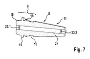
- a kink protection device designated as a whole with K is provided at the outlet of the contact end 4 from the connection opening 6, which is realized in the embodiment shown by a kink protection sleeve 8.
- This consists of a flexible biocompatible elastomer and is molded directly onto the electrode body 3.
- the sleeve body is divided into a contact 5 at the contact end 4 facing fixing 9, a circumferential peripheral part P annular groove 10 and a frusto-conical tapered Tüllen Scheme 11.
- the cylindrically shaped fixing 9 of the anti-buckling sleeve 8 has an inner cylindrical receiving recess as a counterpart 12, the mouth forms the connection opening 6 and is aligned coaxially thereto.
- an insert 17 made of plastic, metal, elastomer or ceramic for reinforcing the sleeve can be embedded in the anti-buckling sleeve 8.
- a circumferential sealing shoulder 18 is provided as a sealing element in the region of the fixing 9, which cooperates with the opposite to the outer diameter of the sealing shoulder 18 slightly smaller inner diameter of the recess 12 and when inserting the anti-buckling sleeve 8 in the recess 12 provides for a corresponding seal.
- FIGS. 5 and 6 show a displaceable on the electrode body 3 version of the anti-buckling sleeve 8 .
- Fig. 5 namely, the electrode 1 is already inserted with its contact end 4 in the connection opening 6 of the connection head 7 in the end position.
- the anti-buckling sleeve 8 is still at a considerable distance in front of the connection head. 7
- the anti-buckling sleeve 8 To the electrode 1 in this in Fig. 5 Spent by the flexible design of the anti-buckling sleeve 8 of the user, the anti-buckling sleeve 8 between the thumb and forefinger, whereby it is temporarily fixed on the electrode body.
- the anti-buckling sleeve 8 thus acts as a quasi-thickened handle for the electrode body 3, which can thus be easily inserted into the connection opening 6.
- this relaxes again and can - as indicated by the arrow 21 - moved on the electrode body 3 in the direction of the recess 12 and in the in Fig. 6 spent final assembly position can be spent.
Landscapes
- Health & Medical Sciences (AREA)
- General Health & Medical Sciences (AREA)
- Animal Behavior & Ethology (AREA)
- Veterinary Medicine (AREA)
- Public Health (AREA)
- Nuclear Medicine, Radiotherapy & Molecular Imaging (AREA)
- Engineering & Computer Science (AREA)
- Life Sciences & Earth Sciences (AREA)
- Radiology & Medical Imaging (AREA)
- Biomedical Technology (AREA)
- Neurosurgery (AREA)
- Heart & Thoracic Surgery (AREA)
- Neurology (AREA)
- Cardiology (AREA)
- Orthopedic Medicine & Surgery (AREA)
- Electrotherapy Devices (AREA)
Applications Claiming Priority (1)
| Application Number | Priority Date | Filing Date | Title |
|---|---|---|---|
| US201361813187P | 2013-04-18 | 2013-04-18 |
Publications (1)
| Publication Number | Publication Date |
|---|---|
| EP2792385A1 true EP2792385A1 (fr) | 2014-10-22 |
Family
ID=50473089
Family Applications (1)
| Application Number | Title | Priority Date | Filing Date |
|---|---|---|---|
| EP14163712.4A Withdrawn EP2792385A1 (fr) | 2013-04-18 | 2014-04-07 | Dispositif de liaison amovible de contacts pour électrodes sur un instrument électromédical |
Country Status (2)
| Country | Link |
|---|---|
| US (1) | US9302095B2 (fr) |
| EP (1) | EP2792385A1 (fr) |
Citations (5)
| Publication number | Priority date | Publication date | Assignee | Title |
|---|---|---|---|---|
| US5489225A (en) * | 1993-12-16 | 1996-02-06 | Ventritex, Inc. | Electrical terminal with a collet grip for a defibrillator |
| US20020161413A1 (en) * | 2001-04-26 | 2002-10-31 | Cardiac Pacemakers, Inc. | Terminal design |
| US20030018364A1 (en) * | 2001-07-17 | 2003-01-23 | Medtronic, Inc. | Enhanced method and apparatus to identify and connect a small diameter lead with a low profile lead connector |
| US20050222634A1 (en) * | 2004-04-02 | 2005-10-06 | Flickinger William J | Connector systems and methods for implantable leads |
| US20100029127A1 (en) * | 2008-07-31 | 2010-02-04 | Rob Sjostedt | Device for securing leads into in-line connector devices |
Family Cites Families (1)
| Publication number | Priority date | Publication date | Assignee | Title |
|---|---|---|---|---|
| WO2008153451A1 (fr) * | 2007-06-13 | 2008-12-18 | St. Jude Medical Ab | Dérivation médicale implantable et procédé de montage de celle-ci |
-
2014
- 2014-04-03 US US14/244,360 patent/US9302095B2/en not_active Expired - Fee Related
- 2014-04-07 EP EP14163712.4A patent/EP2792385A1/fr not_active Withdrawn
Patent Citations (5)
| Publication number | Priority date | Publication date | Assignee | Title |
|---|---|---|---|---|
| US5489225A (en) * | 1993-12-16 | 1996-02-06 | Ventritex, Inc. | Electrical terminal with a collet grip for a defibrillator |
| US20020161413A1 (en) * | 2001-04-26 | 2002-10-31 | Cardiac Pacemakers, Inc. | Terminal design |
| US20030018364A1 (en) * | 2001-07-17 | 2003-01-23 | Medtronic, Inc. | Enhanced method and apparatus to identify and connect a small diameter lead with a low profile lead connector |
| US20050222634A1 (en) * | 2004-04-02 | 2005-10-06 | Flickinger William J | Connector systems and methods for implantable leads |
| US20100029127A1 (en) * | 2008-07-31 | 2010-02-04 | Rob Sjostedt | Device for securing leads into in-line connector devices |
Also Published As
| Publication number | Publication date |
|---|---|
| US9302095B2 (en) | 2016-04-05 |
| US20140316498A1 (en) | 2014-10-23 |
Similar Documents
| Publication | Publication Date | Title |
|---|---|---|
| EP2144740B1 (fr) | Procédé de fabrication d'un produit en plastique comprenant un composant dur en plastique et un composant mou en plastique et produit en plastique fabriqué suivant ledit procédé | |
| EP2092843B1 (fr) | Applicateur doté d'éléments en saillie de maintien de type col, notamment pour du mascara ou des cosmétiques analogues | |
| DE60105578T2 (de) | Elektrische zahnbürste mit auswechselbarem kopfteil | |
| DE3515819C2 (fr) | ||
| EP2416837B1 (fr) | Élement de raccord pour un tube d'une sonde entérale d'alimentation et ensemble composé d'une sonde d'alimentation entérale et d'un système de transfert entéral | |
| EP3057407B1 (fr) | Manchon trayeur et buse | |
| DE202015003233U1 (de) | Interdental-Reinigungsvorrichtung | |
| EP2368518B1 (fr) | Transfert pour implant dentaire | |
| EP2792385A1 (fr) | Dispositif de liaison amovible de contacts pour électrodes sur un instrument électromédical | |
| EP2241349B1 (fr) | Elément d'étanchéité pour une fiche de raccordement doté d'une moindre résistance d'assemblage | |
| EP3518816B1 (fr) | Capuchon à fixer sur un élément d'ancrage | |
| EP3024374B1 (fr) | Élément d'étanchéité pour connecteur d'endoscope | |
| EP2947364A1 (fr) | Dispositif de raccord pour flexibles et appareil de massage doté d'un tel dispositif de raccord | |
| DE102014007390A1 (de) | Anschlusseinheit für eine Kupplungsvorrichtung, insbesondere eine Mehrfachkupplung | |
| EP3630000B1 (fr) | Dispositif de nettoyage interdentaire et procédé pour la fabrication d'un dispositif de nettoyage interdentaire | |
| EP3998986A1 (fr) | Chape de transfert à relier à un implant dentaire | |
| WO2014040778A1 (fr) | Soufflet et procédé de fabrication d'un soufflet | |
| EP0843989B1 (fr) | Système d'implant remplaçant totalement une dent | |
| EP2417889B1 (fr) | Tubulure de raccordement dotée d'élément de ressort | |
| DE102013223593A1 (de) | Verschlusskappe | |
| DE19945219A1 (de) | Warmeinsatzverbindung | |
| DE102008016950B4 (de) | Anordnung aus einem Außenrohr und einem darin eingesetzten Innenrohr | |
| DE202022104964U1 (de) | Vorrichtung für eine Zahnbürste und Zahnbürste | |
| DE102018122930A1 (de) | Verfahren zum Verbinden einer Implantatbasis mit einer Implantatkrone sowie Reinigungswerkzeuge dafür | |
| EP3861966A1 (fr) | Bras prothétique |
Legal Events
| Date | Code | Title | Description |
|---|---|---|---|
| PUAI | Public reference made under article 153(3) epc to a published international application that has entered the european phase |
Free format text: ORIGINAL CODE: 0009012 |
|
| 17P | Request for examination filed |
Effective date: 20140407 |
|
| AK | Designated contracting states |
Kind code of ref document: A1 Designated state(s): AL AT BE BG CH CY CZ DE DK EE ES FI FR GB GR HR HU IE IS IT LI LT LU LV MC MK MT NL NO PL PT RO RS SE SI SK SM TR |
|
| AX | Request for extension of the european patent |
Extension state: BA ME |
|
| R17P | Request for examination filed (corrected) |
Effective date: 20150323 |
|
| RBV | Designated contracting states (corrected) |
Designated state(s): AL AT BE BG CH CY CZ DE DK EE ES FI FR GB GR HR HU IE IS IT LI LT LU LV MC MK MT NL NO PL PT RO RS SE SI SK SM TR |
|
| 17Q | First examination report despatched |
Effective date: 20160825 |
|
| STAA | Information on the status of an ep patent application or granted ep patent |
Free format text: STATUS: THE APPLICATION IS DEEMED TO BE WITHDRAWN |
|
| 18D | Application deemed to be withdrawn |
Effective date: 20170307 |