EP2792385A1 - Releasable contact connection arrangement for electrodes on an electromedical device - Google Patents
Releasable contact connection arrangement for electrodes on an electromedical device Download PDFInfo
- Publication number
- EP2792385A1 EP2792385A1 EP14163712.4A EP14163712A EP2792385A1 EP 2792385 A1 EP2792385 A1 EP 2792385A1 EP 14163712 A EP14163712 A EP 14163712A EP 2792385 A1 EP2792385 A1 EP 2792385A1
- Authority
- EP
- European Patent Office
- Prior art keywords
- contact
- electrode
- sleeve
- connection device
- buckling
- Prior art date
- Legal status (The legal status is an assumption and is not a legal conclusion. Google has not performed a legal analysis and makes no representation as to the accuracy of the status listed.)
- Withdrawn
Links
Images


Classifications
-
- A—HUMAN NECESSITIES
- A61—MEDICAL OR VETERINARY SCIENCE; HYGIENE
- A61N—ELECTROTHERAPY; MAGNETOTHERAPY; RADIATION THERAPY; ULTRASOUND THERAPY
- A61N1/00—Electrotherapy; Circuits therefor
- A61N1/02—Details
- A61N1/04—Electrodes
- A61N1/05—Electrodes for implantation or insertion into the body, e.g. heart electrode
- A61N1/0551—Spinal or peripheral nerve electrodes
-
- A—HUMAN NECESSITIES
- A61—MEDICAL OR VETERINARY SCIENCE; HYGIENE
- A61N—ELECTROTHERAPY; MAGNETOTHERAPY; RADIATION THERAPY; ULTRASOUND THERAPY
- A61N1/00—Electrotherapy; Circuits therefor
- A61N1/18—Applying electric currents by contact electrodes
- A61N1/32—Applying electric currents by contact electrodes alternating or intermittent currents
- A61N1/36—Applying electric currents by contact electrodes alternating or intermittent currents for stimulation
- A61N1/372—Arrangements in connection with the implantation of stimulators
- A61N1/375—Constructional arrangements, e.g. casings
- A61N1/3752—Details of casing-lead connections
-
- H—ELECTRICITY
- H01—ELECTRIC ELEMENTS
- H01R—ELECTRICALLY-CONDUCTIVE CONNECTIONS; STRUCTURAL ASSOCIATIONS OF A PLURALITY OF MUTUALLY-INSULATED ELECTRICAL CONNECTING ELEMENTS; COUPLING DEVICES; CURRENT COLLECTORS
- H01R13/00—Details of coupling devices of the kinds covered by groups H01R12/70 or H01R24/00 - H01R33/00
- H01R13/46—Bases; Cases
- H01R13/52—Dustproof, splashproof, drip-proof, waterproof, or flameproof cases
- H01R13/5224—Dustproof, splashproof, drip-proof, waterproof, or flameproof cases for medical use
-
- H—ELECTRICITY
- H01—ELECTRIC ELEMENTS
- H01R—ELECTRICALLY-CONDUCTIVE CONNECTIONS; STRUCTURAL ASSOCIATIONS OF A PLURALITY OF MUTUALLY-INSULATED ELECTRICAL CONNECTING ELEMENTS; COUPLING DEVICES; CURRENT COLLECTORS
- H01R2201/00—Connectors or connections adapted for particular applications
- H01R2201/12—Connectors or connections adapted for particular applications for medicine and surgery
Abstract
Eine lösbare Kontaktverbindungseinrichtung für Elektroden an einem elektromedizinischen Gerät, insbesondere für Elektroden von aktiven Implantaten wie z.B. Neurostimulator-Geräten, umfasst - ein an der Elektrode (1) vorgesehenes Kontaktende (4) mit mindestens einem elektrischen Kontakt (5), - einen geräteseitigen Anschlusskopf (7) am elektromedizinischen Gerät (2), - eine Anschlussöffnung (6) am Anschlusskopf (7) zur Verankerung des Kontaktendes (4) der Elektrode (1) unter Herstellung einer elektrischen Kontaktverbindung und lösbaren mechanischen Fixierung, und - eine Knickschutzeinrichtung (K) am Austritt des Kontaktendes (4) aus der Anschlussöffnung (6), - wobei die Knickschutzeinrichtung (K) eine vor dem mindestens einen elektrischen Kontakt (5) auf dem Kontaktende (4) der Elektrode (1) sitzende, flexible Knickschutz-Hülse (8) aufweist, die mit ihrem dem Anschlusskopf (7) zugewandten Fixierende (9) in eine gegenüber der Anschlussöffnung (6) erweiterten Aufnahme-Aussparung (12) eingeschoben und befestigt ist.A detachable contact connection device for electrodes on an electromedical device, in particular for electrodes of active implants, e.g. Neurostimulator devices a contact end (4) provided on the electrode (1) with at least one electrical contact (5), a device-side connection head (7) on the electromedical device (2), - A connection opening (6) on the connection head (7) for anchoring the contact end (4) of the electrode (1) to produce an electrical contact connection and releasable mechanical fixation, and - An anti-buckling device (K) at the outlet of the contact end (4) from the connection opening (6), - wherein the anti-buckling device (K) has a front of the at least one electrical contact (5) on the contact end (4) of the electrode (1) sitting flexible anti-buckling sleeve (8) facing with its the connection head (7) fixing end ( 9) in a relation to the connection opening (6) extended receiving recess (12) is inserted and fixed.
Description
Die Erfindung betrifft eine lösbare Kontaktverbindungseinrichtung für Elektroden an einem elektromedizinischen Gerät, insbesondere für Elektroden von implantierbaren Neurostimulator-Geräten, mit den im Oberbegriff des Patentanspruches 1 angegebenen Merkmalen.The invention relates to a releasable contact connection device for electrodes on an electromedical device, in particular for electrodes of implantable neurostimulator devices, having the features specified in the preamble of
Derartige lösbare Kontaktverbindungseinrichtungen umfassen üblicherweise ein an der Elektrode vorgesehenes Kontaktende mit mindestens einem elektrischen Kontakt, einen geräteseitigen Anschlusskopf am elektromedizinischen Gerät, eine Anschlussöffnung am Anschlusskopf zur Verankerung des Kontaktendes der Elektrode unter Herstellung einer elektrischen Kontaktverbindung und lösbaren mechanischen Fixierung, sowie eine Knickschutzeinrichtung am Austritt des Kontaktendes aus der Anschlussöffnung.Such detachable contact connection devices usually comprise a contact end provided on the electrode with at least one electrical contact, a device-side connection head on the electromedical device, a connection opening on the connection head for anchoring the contact end of the electrode to produce an electrical contact connection and releasable mechanical fixation, and a kink protection device at the outlet of the Contact end from the connection opening.
Zum Hintergrund der Erfindung ist festzuhalten, dass derartige lösbare Kontaktverbindungseinrichtungen, besonders wenn sie bei Elektroden für Neurostimulatoren eingesetzt werden, einen sogenannten "360°-Knickschutz" am Übergang vom geräteseitigen Anschluss zur Elektrode benötigen, da die Elektrode solcher elektromedizinischer Geräte seitlich praktisch in alle Raumrichtungen aus der Längsachse des Anschlussendes ausgelenkt werden kann.To the background of the invention it should be noted that such detachable contact connection devices, especially when used in electrodes for neurostimulators, require a so-called "360 ° kink protection" at the transition from the device-side terminal to the electrode, since the electrode of such electromedical devices laterally in virtually all spatial directions can be deflected from the longitudinal axis of the terminal end.
Die in diesem Zusammenhang notwendige Knickschutzeinrichtung ist aus dem Stand der Technik gemäß offenkundiger Vorbenutzung seitens der Anmelderin grundsätzlich bekannt. Sie besteht aus einem um die Mündung der Anschlussöffnung am Anschlusskopf des elektromedizinischen Gerätes angeformten Stutzen in Kombination mit einer auf der Elektrode verschiebbaren Knickschutztülle. Auch ein aus dem Anschlusskopf herausragendes Schlauchstück ist bekannt und erfüllt den Zweck einer Knickschutzmaßnahme.The anti-buckling device necessary in this context is known from the prior art according to obvious prior use by the applicant in principle. It consists of a formed around the mouth of the connection opening at the connection head of the electromedical device nozzle in combination with a on the Electrode sliding anti-kink sleeve. Also, an outstanding from the connection head hose piece is known and fulfills the purpose of a kink protection measure.
Diese bekannten Lösungen haben den Nachteil, dass sie von der an sich glattflächigen Oberfläche des Anschlusskopfes vorspringen, was ein Nacharbeiten der Oberflächen des Anschlusskopfes, wie beispielsweise ein Entgraten und Polieren, nicht erlaubt. Der Grund hierfür liegt in erster Linie darin, dass diese Anschlussköpfe zur Ausbildung dieser Knickschutzeinrichtungen in der Regel komplett aus Vergussharz gebildet sind, was eine Oberflächenveredelung zur Erfüllung hoher Qualitätsansprüche erschwert.These known solutions have the disadvantage that they project from the smooth surface on the surface of the connection head, which does not allow reworking of the surfaces of the connection head, such as a deburring and polishing. The reason for this lies primarily in the fact that these connection heads for the formation of these anti-buckling devices are usually formed completely of casting resin, which complicates a surface finishing to meet high quality standards.
Ausgehend von der geschilderten Problematik des Standes der Technik liegt der Erfindung die Aufgabe zugrunde, eine Knickschutzeinrichtung an einer gattungsgemäßen lösbaren Kontaktverbindungseinrichtung zu schaffen, die eine unabhängige Nachbearbeitung des Anschlusskopfes des elektromedizinischen Gerätes bei hoher Knickschutzwirkung erlaubt.Based on the described problem of the prior art, the present invention seeks to provide a buckling protection device on a generic releasable contact connection device that allows independent post-processing of the connection head of the electromedical device with high kink protection effect.
Die Aufgabe wird durch die im Kennzeichnungsteil des Anspruches 1 angegebenen Merkmale gelöst. Demnach weist die Knickschutzeinrichtung eine vor dem mindestens einen elektrischen Kontakt auf dem Kontaktende der Elektrode sitzende, flexible, also biegsame Knickschutz-Hülse auf, die mit ihrem dem Anschlusskopf zugewandten Fixierende in eine gegenüber der Anschlussöffnung erweiterten Aufnahme-Aussparung eingeschoben befestigt ist.The object is achieved by the features stated in the characterizing part of
Grundkonzept der Erfindung ist also die räumliche Trennung der Knickschutzeinrichtung vom Anschlusskopf, der lediglich eine entsprechende Aufnahme-Aussparung für das Fixierende der Knickschutz-Hülse aufweisen muss. Da diese Aussparung keinen Vorsprung an der Oberfläche des Anschlusskopfes, sondern lediglich eine Vertiefung oder Einbuchtung bildet, die bei angeschlossener Elektrode ohnehin durch das Fixierende der Knickschutz-hülse geschlossen ist, können am Anschlusskopf problemlos Nacharbeiten der Oberfläche vorgenommen und der Anschlusskopf selbst aus einem hinsichtlich seiner Oberflächengüte ausgewählten Material bestehen. Die Verwendung eines Vergussharzes für die Herstellung des Anschlusskopfes ist wegen des weggefallenen Tüllen- oder Schlauchvorsprungs am Anschlusskopf problemlos möglich. Gleichwohl wird durch die Knickschutz-Hülse ein wirkungsvoller 360°-Schutz am Übergang zum Anschlusskopf gewährleistet, der auch größeren Kräften und Muskelbewegungen, wie sie gerade im Umfeld von aktiven Implantaten wie z.B. Neurostimulator-Geräten auftreten können, widersteht.The basic concept of the invention is thus the physical separation of the anti-buckling device from the connection head, which only has to have a corresponding receiving recess for the fixing end of the anti-buckling sleeve. Since this recess does not form a projection on the surface of the connection head, but only a depression or indentation, which is anyway closed by the fixing of the kink protection sleeve at the connected electrode, the surface can be easily reworked on the connection head and the connection head itself from a respect to his Surface quality selected material. The use of a potting resin for the production of the connection head is easily possible because of the omitted Tüllen- or hose projection on the connection head. Nevertheless, the kink protection sleeve is inserted ensures effective 360 ° protection at the transition to the connection head, which also withstands larger forces and muscle movements that can occur in the vicinity of active implants such as neurostimulator devices.
In den abhängigen Ansprüchen sind bevorzugte Weiterbildungen des Erfindungsgegenstandes angegeben. So kann es vorgesehen sein, dass die in Längsaxialrichtung weisende Kopffläche der Knickschutz-Hülse als Anschlagfläche mit der Bodenfläche der erweiterten Aufnahme-Aussparung kooperiert. Damit bildet die Knickschutz-Hülse gleichzeitig den Anschlag für das Einschieben des Kontaktendes der Elektrode in die Anschlussöffnung des Gerätes. Damit ist die Einstecktiefe des Anschlussendes festgelegt.In the dependent claims preferred developments of the subject invention are given. Thus, it can be provided that the longitudinal axis direction-facing head surface of the anti-buckling sleeve cooperates as a stop surface with the bottom surface of the enlarged receiving recess. Thus, the kink protection sleeve simultaneously forms the stop for the insertion of the contact end of the electrode into the connection opening of the device. This defines the insertion depth of the connection end.
Gemäß einer bevorzugten Weiterbildung ist es vorgesehen, dass die Knickschutz-Hülse in einem Abstand von ihrer Kopffläche, der der Tiefe der Aufnahme-Aussparung entspricht, mit einer Markierung versehen ist. Damit ist eine optische Kontrollmöglichkeit für die Positionierung der Elektrode im angeschlossenen Zustand gegeben.According to a preferred embodiment, it is provided that the kink protection sleeve is provided with a mark at a distance from its top surface, which corresponds to the depth of the receiving recess. This provides a visual control of the positioning of the electrode in the connected state.
Vorzugsweise wird die Markierung durch eine in Peripherrichtung umlaufende Ringnut in der Knickschutz-Hülse gebildet. Damit kann auch "blind" mit Hilfe des Tastsinns die Positionierung des Kontaktendes der Elektrode in der Anschlussöffnung erfühlt werden.Preferably, the marking is formed by an annular groove extending in the peripheral direction in the anti-buckling sleeve. Thus, the positioning of the contact end of the electrode in the connection opening can also be felt "blindly" by means of the sense of touch.
Die gemäß einer weiteren bevorzugten Ausführungsform mögliche kegelstumpfförmige, sich in Richtung der Elektrode verjüngende Gestalt der Knickschutz-Hülse unterstützt die schonende Behandlung der Elektrode bei ihrer Auslenkung aus der Axialrichtung der Anschlussöffnung im Anschlusskopf.The frustoconical shape of the anti-kink sleeve, which is tapered in the direction of the electrode and which is possible in accordance with a further preferred embodiment, supports the gentle treatment of the electrode during its deflection from the axial direction of the connection opening in the connection head.
Eine herstellungstechnisch einfache und materialtechnisch vorteilhafte Weiterbildung sieht die Herstellung der Knickschutz-Hülse aus einem vollvolumigen, spritzgegossenen, flexiblen biokompatiblen Elastomer vorzugsweise in Kombination mit mindestens einem Stützelement aus Keramik, Metall oder Kunststoff vor.A manufacturing technically simple and material-technically advantageous development provides for the manufacture of the anti-buckling sleeve of a full-volume, injection-molded, flexible biocompatible elastomer, preferably in combination with at least one support element made of ceramic, metal or plastic.
Für die Anordnung der Knickschutz-Hülse auf der Elektrode sind zwei grundsätzliche Alternativen möglich, nämlich einerseits eine ortsfeste Fixierung der Knickschutz-Hülse auf dem Kontaktende der Elektrode. Dadurch ist eine saubere und exakte Zuordnung der Position der Knickschutz-Hülse zum Kontaktende und damit auch relativ zur Anschlussöffnung möglich, so dass die Anschlagfunktion und Positionierungskontrolle durch das Einschieben der Knickschutz-Hülse in die Aussparung der Aufnahmeöffnung besonders zuverlässig möglich sind.For the arrangement of the anti-buckling sleeve on the electrode two basic alternatives are possible, namely on the one hand a fixed fixation of the anti-buckling sleeve on the contact end of the electrode. As a result, a clean and accurate assignment of the position of the kink protection sleeve to the contact end and thus also relative to the connection opening is possible, so that the stop function and positioning control are particularly reliable possible by inserting the kink protection sleeve in the recess of the receiving opening.
Herstellungstechnisch einfach ist das gemäß einer weiteren bevorzugten Ausführungsform vorgesehene Anspritzen der Knickschutz-Hülse direkt an das Kontaktende der Elektrode.In terms of manufacturing technology, injection molding of the anti-kink sleeve provided according to a further preferred embodiment is direct to the contact end of the electrode.
Auch ein Aufschweißen oder Aufkleben sind als Variante davon möglich, wobei dann in letzterem Fall ein biokompatibler Klebstoff vorzuziehen ist.Welding or gluing are also possible as a variant, in which case a biocompatible adhesive is to be preferred in the latter case.
Als Alternative zu der festen Verbindung zwischen Knickschutz-Hülse und Elektrode kann auch deren verschiebbare Lagerung auf der Elektrode vorgesehen sein.As an alternative to the fixed connection between the anti-kink sleeve and the electrode, its displaceable mounting on the electrode can also be provided.
Gemäß einer weiteren bevorzugten Ausführungsform kann die längsaxial verlaufende Hülsenöffnung der Knickschutz-Hülse durch mindestens ein Dichtelement gegenüber dem Kontaktende der Elektrode abgedichtet sein. Damit können axiale und radiale Dichtfunktionen durch die Knickschutz-Hülse übernommen werden. Für die Ausbildung des Dichtelementes können übliche Konfigurationen, wie ein Dichtring, eine ballige Dichtfläche oder eine Dichtlippe vorgesehen werden. Wenn die Knickschutz-Hülle aus einem flexiblen Material, wie beispielsweise aus Silikon gefertigt ist, sind derartige Dichtelemente problemlos an der Knickschutz-Hülse auszubilden.According to a further preferred embodiment, the longitudinally extending sleeve opening of the anti-buckling sleeve can be sealed off by at least one sealing element with respect to the contact end of the electrode. Thus, axial and radial sealing functions can be taken over by the kink protection sleeve. For the formation of the sealing element conventional configurations, such as a sealing ring, a crowned sealing surface or a sealing lip can be provided. If the anti-buckling sheath is made of a flexible material, such as silicone, such sealing elements are easily formed on the anti-buckling sleeve.
Diese flexible Ausbildung ist im Übrigen auch im Zusammenhang mit der Verschiebbarkeit der Knickschutz-Hülse auf der Elektrode von Vorteil. Durch eine insbesondere radial nach innen flexible Spezifikation des Materials der Knickschutz-Hülse kann ein Anwender diese zwischen Daumen und Zeigefinger zusammenpressen, womit eine temporäre Fixierung der Hülse auf der Elektrodenleitung erfolgt, die durch Loslassen wieder gelöst werden kann.Incidentally, this flexible design is also advantageous in connection with the displaceability of the anti-kink sleeve on the electrode. By a particular radially inwardly flexible specification of the material of the anti-kink sleeve, a user can compress them between the thumb and forefinger, which is a temporary fixation of the sleeve on the electrode line, which can be solved by releasing again.
Eine weitere bevorzugte Dichtungsmaßnahme kann darin bestehen, auf der Außenseite des Fixierendes der Knickschutz-Hülse eine umlaufende Dichtschulter vorzusehen, die mit der Innenwand der Aufnahme-Aussparung kooperiert und damit die Aussparung hermetisch abdichtet.Another preferred sealing measure may be to provide on the outside of the fixing of the anti-buckling sleeve, a circumferential sealing shoulder, which cooperates with the inner wall of the receiving recess and thus hermetically seals the recess.
Ferner kann vorgesehen sein, zur weiter verbesserten Fixierung der Knickschutz-Hülse in der Aussparung eine Befestigungseinrichtung insbesondere in Form einer Verrastung zwischen beiden Bauteilen vorzusehen, die durch eine am Fixierende umlaufende Befestigungsschulter und eine entsprechende Ringnut in der Innenwand der Aussparung gebildet sein kann. In der Montagestellung der Knickschutz-Hülse rastet diese Befestigungsschulter dann in die Ringnut ein und sorgt für einen sicheren Halt.Furthermore, it can be provided to provide for further improved fixation of the anti-buckling sleeve in the recess, a fastening device, in particular in the form of a latching between the two components, which may be formed by a peripheral fixing at the fixing shoulder and a corresponding annular groove in the inner wall of the recess. In the assembled position of the anti-kink sleeve, this fastening shoulder then snaps into the annular groove and ensures a secure hold.
Schließlich liegt eine weitere bevorzugte Weiterbildung der Kontaktverbindungseinrichtung darin, die Mündung der Anschlussöffnung und/oder die Kopffläche der Knickschutz-Hülse mit einer umlaufenden Fase zu versehen. Diese Anfasung bewirkt eine Selbstzentrierung der Knickschutz-Hülse beim ihrem Einführen in die Aussparung im Anschlusskopf. Die Anwendung des elektromedizinischen Gerätes wird damit erleichtert.Finally, another preferred development of the contact connection device is to provide the mouth of the connection opening and / or the top surface of the anti-buckling sleeve with a circumferential chamfer. This chamfering causes a self-centering of the anti-buckling sleeve during its insertion into the recess in the connection head. The application of the electromedical device is thus facilitated.
Weitere Merkmale, Einzelheiten und Vorteile der Erfindung ergeben sich aus der nachfolgenden Beschreibung eines Ausführungsbeispiels anhand der beigefügten Zeichnungen. Es zeigen:
- Fig. 1
- eine perspektivische Teilansicht einer Elektrode im Bereich ihres Kontaktendes mit Knickschutz-Hülse,
- Fig. 2
- eine perspektivische Teilansicht einer Elektrode analog
Fig. 1 mit einem elektromedizinischen Gerät vor dem Einführen des Kontaktendes der Elektrode in den Anschlusskopf des Gerätes, - Fig. 3
- eine perspektivische Teildarstellung von Elektrode und Gerät mit Anschlusskopf im kontaktierten Zustand,
- Fig. 4
- eine perspektivische Teilansicht einer Elektrode im Bereich ihres Kontaktendes mit Knickschutz-Hülse in einer zweiten Ausführungsform,
- Fig. 5
- eine perspektivische Teilansicht einer Elektrode analog
Fig. 4 mit einem elektromedizinischen Gerät vor dem Einführen des Kontaktendes der Elektrode in den Anschlusskopf des Gerätes, - Fig. 6
- eine perspektivische Darstellung der Elektrode gemäß
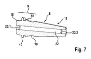
Fig. 4 und 5 sowie eines elektromedizinischen Geräts mit dem Anschlusskopf im kontaktierten Zustand, und - Fig. 7
- einen perspektivischen Längsaxialschnitt der bei den Elektroden gemäß
Fig. 4 bis 6 verwendeten Knickschutz-Hülse.
- Fig. 1
- a perspective partial view of an electrode in the region of its contact end with anti-kink sleeve,
- Fig. 2
- a partial perspective view of an electrode analog
Fig. 1 with an electromedical device before inserting the contact end of the electrode into the connection head of the device, - Fig. 3
- a partial perspective view of electrode and device with connection head in the contacted state,
- Fig. 4
- 3 a perspective partial view of an electrode in the region of its contact end with an antikink sleeve in a second embodiment,
- Fig. 5
- a partial perspective view of an electrode analog
Fig. 4 with an electromedical device before inserting the contact end of the electrode into the connection head of the device, - Fig. 6
- a perspective view of the electrode according to
4 and 5 and an electromedical device with the connection head in the contacted state, and - Fig. 7
- a perspective longitudinal axial section of the electrodes according to
4 to 6 used anti-kink sleeve.
Wie aus den
Diese kooperieren mit entsprechenden Gegenkontakten (nicht dargestellt) im Anschlusskopf 7 des Gerätes 2, die mit der elektronischen Gerätesteuerung des Geräts 2 entsprechend verschaltet sind.These cooperate with corresponding mating contacts (not shown) in the
Zum Schutz der Elektrode 1 gegen dynamische Bewegungen, Biegemomente und dergleichen ist eine als Ganzes mit K bezeichnete Knickschutzeinrichtung am Austritt des Kontaktendes 4 aus der Anschlussöffnung 6 vorgesehen, die im gezeigten Ausführungsbeispiel durch eine Knickschutz-Hülse 8 realisiert ist. Diese besteht aus einem flexiblen biokompatiblen Elastomer und ist direkt an den Elektrodenkörper 3 angespritzt. Der Hülsenkörper gliedert sich dabei in ein den Kontakten 5 am Kontaktende 4 zugewandtes Fixierende 9, eine in Peripherrichtung P umlaufende Ringnut 10 und einen sich kegelstumpfförmig verjüngenden Tüllenbereich 11. Das zylindrisch ausgebildete Fixierende 9 der Knickschutz-Hülse 8 hat als Gegenpart eine innenzylindrische Aufnahme-Aussparung 12, die die Mündung der Anschlussöffnung 6 bildet und koaxial dazu ausgerichtet ist. Der Abstand a der Ringnut 10 von der Kopffläche 13 des Fixierendes 9 entspricht der Tiefe T der Aufnahme-Aussparung 12. Wird das Kontaktende 4 der Elektrode 1 in die Anschlussöffnung 6 eingeschoben, wirkt die Kopffläche 13 mit dem Boden 14 der Aussparung 12 als Anschlag zusammen, so dass die Ringnut 10 dann als eine optische und ertastbare Markierung M für die korrekte Positionierung des Kontaktendes 4 der Elektrode 1 in der Anschlussöffnung 6 fungiert, wie dies anhand von
Schließlich geht aus
Wie in
Die in den
Wesentliche Unterschiede der Ausführungsform gemäß
Significant differences of the embodiment according to
Ferner ist in Richtung zum Kontaktende 4 der Elektrode 1 hin vor der Dichtschulter 18 eine im Außendurchmesser und Querschnitt größere Befestigungsschulter 19 angeformt, die als in Umfangsrichtung umlaufender Ringvorsprung ausgebildet ist. Diese Befestigungsschulter 19 kooperiert mit einer entsprechenden Ringnut 20 in der Innenwand der Aussparung 12. Nach dem Einschieben der Knickschutz-Hülse 8 in die Aussparung 12 rastet die Befestigungsschulter 19 in die Ringnut 20 ein, wodurch eine besonders stabile Verankerung der Knickschutz-Hülse 8 im Anschlusskopf 7 des Geräts 2 realisiert wird.Further, in the direction of the
Wie aus einer Zusammenschau der
Um die Elektrode 1 in diese in
Um die in
Claims (15)
dadurch gekennzeichnet, dass
characterized in that
Applications Claiming Priority (1)
| Application Number | Priority Date | Filing Date | Title |
|---|---|---|---|
| US201361813187P | 2013-04-18 | 2013-04-18 |
Publications (1)
| Publication Number | Publication Date |
|---|---|
| EP2792385A1 true EP2792385A1 (en) | 2014-10-22 |
Family
ID=50473089
Family Applications (1)
| Application Number | Title | Priority Date | Filing Date |
|---|---|---|---|
| EP14163712.4A Withdrawn EP2792385A1 (en) | 2013-04-18 | 2014-04-07 | Releasable contact connection arrangement for electrodes on an electromedical device |
Country Status (2)
| Country | Link |
|---|---|
| US (1) | US9302095B2 (en) |
| EP (1) | EP2792385A1 (en) |
Citations (5)
| Publication number | Priority date | Publication date | Assignee | Title |
|---|---|---|---|---|
| US5489225A (en) * | 1993-12-16 | 1996-02-06 | Ventritex, Inc. | Electrical terminal with a collet grip for a defibrillator |
| US20020161413A1 (en) * | 2001-04-26 | 2002-10-31 | Cardiac Pacemakers, Inc. | Terminal design |
| US20030018364A1 (en) * | 2001-07-17 | 2003-01-23 | Medtronic, Inc. | Enhanced method and apparatus to identify and connect a small diameter lead with a low profile lead connector |
| US20050222634A1 (en) * | 2004-04-02 | 2005-10-06 | Flickinger William J | Connector systems and methods for implantable leads |
| US20100029127A1 (en) * | 2008-07-31 | 2010-02-04 | Rob Sjostedt | Device for securing leads into in-line connector devices |
Family Cites Families (1)
| Publication number | Priority date | Publication date | Assignee | Title |
|---|---|---|---|---|
| EP2157999B1 (en) * | 2007-06-13 | 2013-05-22 | St. Jude Medical AB | Medical implantable lead |
-
2014
- 2014-04-03 US US14/244,360 patent/US9302095B2/en active Active
- 2014-04-07 EP EP14163712.4A patent/EP2792385A1/en not_active Withdrawn
Patent Citations (5)
| Publication number | Priority date | Publication date | Assignee | Title |
|---|---|---|---|---|
| US5489225A (en) * | 1993-12-16 | 1996-02-06 | Ventritex, Inc. | Electrical terminal with a collet grip for a defibrillator |
| US20020161413A1 (en) * | 2001-04-26 | 2002-10-31 | Cardiac Pacemakers, Inc. | Terminal design |
| US20030018364A1 (en) * | 2001-07-17 | 2003-01-23 | Medtronic, Inc. | Enhanced method and apparatus to identify and connect a small diameter lead with a low profile lead connector |
| US20050222634A1 (en) * | 2004-04-02 | 2005-10-06 | Flickinger William J | Connector systems and methods for implantable leads |
| US20100029127A1 (en) * | 2008-07-31 | 2010-02-04 | Rob Sjostedt | Device for securing leads into in-line connector devices |
Also Published As
| Publication number | Publication date |
|---|---|
| US20140316498A1 (en) | 2014-10-23 |
| US9302095B2 (en) | 2016-04-05 |
Similar Documents
| Publication | Publication Date | Title |
|---|---|---|
| EP2144740B1 (en) | Method for the production of a plastic product having a hard plastic component and a soft plastic component, and plastic product produced using said method | |
| EP2092843B1 (en) | Applicator with collar-like attachment projections, in particular for mascara or similar cosmetics | |
| DE60105578T2 (en) | ELECTRIC TOOTHBRUSH WITH INTERCHANGEABLE HEADSET | |
| DE3515819C2 (en) | ||
| EP2416837B1 (en) | Connection piece for the tube of an enteral feeding tube and assembly of an enteral feeding tube and an enteral transfer system | |
| EP3057407B1 (en) | Teat cup liner and vent | |
| DE202015003233U1 (en) | Interdental cleaning device | |
| EP2368518B1 (en) | Impression coping for a dental implant | |
| DE102014209929B4 (en) | Hose connection device and massage toy with such a hose connection device | |
| EP2792385A1 (en) | Releasable contact connection arrangement for electrodes on an electromedical device | |
| EP2241349B1 (en) | Seal element for a connector with reduced joint resistance | |
| EP3518816B1 (en) | Cap for fastening on an anchoring element | |
| EP3024374B1 (en) | Sealing component for an endoscope connector | |
| EP3630000B1 (en) | Interdental cleaning device and method for producing an interdental cleaning device | |
| EP3998986A1 (en) | Impression post for connection to a dental implant | |
| EP2399541B1 (en) | Dental structure and method for manufacturing the same | |
| WO2014040778A1 (en) | Gaiter and method for producing a gaiter | |
| EP0843989B1 (en) | Complete tooth implant assembly | |
| EP2417889B1 (en) | Connection pipe with spring element | |
| DE102013223593A1 (en) | cap | |
| DE19945219A1 (en) | Hot insert connection | |
| DE102008016950B4 (en) | Arrangement of an outer tube and an inner tube inserted therein | |
| DE202022104964U1 (en) | Device for a toothbrush and toothbrush | |
| DE102018122930A1 (en) | Method for connecting an implant base with an implant crown and cleaning tools therefor | |
| EP3552574A1 (en) | Tooth implant analogue |
Legal Events
| Date | Code | Title | Description |
|---|---|---|---|
| PUAI | Public reference made under article 153(3) epc to a published international application that has entered the european phase |
Free format text: ORIGINAL CODE: 0009012 |
|
| 17P | Request for examination filed |
Effective date: 20140407 |
|
| AK | Designated contracting states |
Kind code of ref document: A1 Designated state(s): AL AT BE BG CH CY CZ DE DK EE ES FI FR GB GR HR HU IE IS IT LI LT LU LV MC MK MT NL NO PL PT RO RS SE SI SK SM TR |
|
| AX | Request for extension of the european patent |
Extension state: BA ME |
|
| R17P | Request for examination filed (corrected) |
Effective date: 20150323 |
|
| RBV | Designated contracting states (corrected) |
Designated state(s): AL AT BE BG CH CY CZ DE DK EE ES FI FR GB GR HR HU IE IS IT LI LT LU LV MC MK MT NL NO PL PT RO RS SE SI SK SM TR |
|
| 17Q | First examination report despatched |
Effective date: 20160825 |
|
| STAA | Information on the status of an ep patent application or granted ep patent |
Free format text: STATUS: THE APPLICATION IS DEEMED TO BE WITHDRAWN |
|
| 18D | Application deemed to be withdrawn |
Effective date: 20170307 |