EP2790588B1 - Automated doppler pulse cycle selection - Google Patents
Automated doppler pulse cycle selection Download PDFInfo
- Publication number
- EP2790588B1 EP2790588B1 EP12816350.8A EP12816350A EP2790588B1 EP 2790588 B1 EP2790588 B1 EP 2790588B1 EP 12816350 A EP12816350 A EP 12816350A EP 2790588 B1 EP2790588 B1 EP 2790588B1
- Authority
- EP
- European Patent Office
- Prior art keywords
- cycles
- cycle
- selection
- further configured
- segments
- Prior art date
- Legal status (The legal status is an assumption and is not a legal conclusion. Google has not performed a legal analysis and makes no representation as to the accuracy of the status listed.)
- Active
Links
- 230000003595 spectral effect Effects 0.000 claims description 16
- 238000001914 filtration Methods 0.000 claims description 7
- 230000000541 pulsatile effect Effects 0.000 claims description 6
- 230000004044 response Effects 0.000 claims description 4
- 238000004590 computer program Methods 0.000 claims description 3
- 238000002604 ultrasonography Methods 0.000 description 25
- 239000000523 sample Substances 0.000 description 19
- 238000005259 measurement Methods 0.000 description 17
- 230000017531 blood circulation Effects 0.000 description 16
- 238000000034 method Methods 0.000 description 14
- 210000004204 blood vessel Anatomy 0.000 description 13
- 210000001367 artery Anatomy 0.000 description 10
- 238000013442 quality metrics Methods 0.000 description 9
- 230000001605 fetal effect Effects 0.000 description 7
- 238000003384 imaging method Methods 0.000 description 7
- 230000006870 function Effects 0.000 description 6
- 238000012545 processing Methods 0.000 description 5
- 230000000747 cardiac effect Effects 0.000 description 4
- 238000009556 duplex ultrasonography Methods 0.000 description 4
- 230000008774 maternal effect Effects 0.000 description 4
- 210000001644 umbilical artery Anatomy 0.000 description 4
- 210000000685 uterine artery Anatomy 0.000 description 4
- 238000000827 velocimetry Methods 0.000 description 4
- 230000000007 visual effect Effects 0.000 description 4
- 210000003484 anatomy Anatomy 0.000 description 3
- 238000003491 array Methods 0.000 description 3
- 210000001715 carotid artery Anatomy 0.000 description 3
- 238000003745 diagnosis Methods 0.000 description 3
- 238000010586 diagram Methods 0.000 description 3
- 210000001519 tissue Anatomy 0.000 description 3
- 238000012935 Averaging Methods 0.000 description 2
- 208000005764 Peripheral Arterial Disease Diseases 0.000 description 2
- 208000030831 Peripheral arterial occlusive disease Diseases 0.000 description 2
- 230000001133 acceleration Effects 0.000 description 2
- 230000005540 biological transmission Effects 0.000 description 2
- 239000008280 blood Substances 0.000 description 2
- 210000004369 blood Anatomy 0.000 description 2
- 238000003759 clinical diagnosis Methods 0.000 description 2
- 230000001419 dependent effect Effects 0.000 description 2
- 238000001514 detection method Methods 0.000 description 2
- 238000002059 diagnostic imaging Methods 0.000 description 2
- 230000003205 diastolic effect Effects 0.000 description 2
- 210000002254 renal artery Anatomy 0.000 description 2
- 238000005096 rolling process Methods 0.000 description 2
- 230000002792 vascular Effects 0.000 description 2
- 208000032843 Hemorrhage Diseases 0.000 description 1
- 208000036818 High risk pregnancy Diseases 0.000 description 1
- 230000002159 abnormal effect Effects 0.000 description 1
- 230000002547 anomalous effect Effects 0.000 description 1
- 210000001765 aortic valve Anatomy 0.000 description 1
- 238000004422 calculation algorithm Methods 0.000 description 1
- 238000004364 calculation method Methods 0.000 description 1
- 210000001627 cerebral artery Anatomy 0.000 description 1
- 230000000295 complement effect Effects 0.000 description 1
- 229940079593 drug Drugs 0.000 description 1
- 239000003814 drug Substances 0.000 description 1
- 238000005516 engineering process Methods 0.000 description 1
- 230000005284 excitation Effects 0.000 description 1
- 238000000605 extraction Methods 0.000 description 1
- 238000005206 flow analysis Methods 0.000 description 1
- 230000000004 hemodynamic effect Effects 0.000 description 1
- 238000000338 in vitro Methods 0.000 description 1
- 238000001727 in vivo Methods 0.000 description 1
- 238000011221 initial treatment Methods 0.000 description 1
- 208000014674 injury Diseases 0.000 description 1
- 238000009434 installation Methods 0.000 description 1
- 238000005304 joining Methods 0.000 description 1
- 238000004519 manufacturing process Methods 0.000 description 1
- 210000004115 mitral valve Anatomy 0.000 description 1
- 238000012544 monitoring process Methods 0.000 description 1
- 230000003287 optical effect Effects 0.000 description 1
- 230000035935 pregnancy Effects 0.000 description 1
- 230000001902 propagating effect Effects 0.000 description 1
- 238000009877 rendering Methods 0.000 description 1
- 238000012552 review Methods 0.000 description 1
- 238000005070 sampling Methods 0.000 description 1
- 238000012216 screening Methods 0.000 description 1
- 210000004872 soft tissue Anatomy 0.000 description 1
- 238000003860 storage Methods 0.000 description 1
- 238000012360 testing method Methods 0.000 description 1
- 238000013519 translation Methods 0.000 description 1
- 230000008733 trauma Effects 0.000 description 1
- 210000000591 tricuspid valve Anatomy 0.000 description 1
- 230000036642 wellbeing Effects 0.000 description 1
Images

Classifications
-
- A—HUMAN NECESSITIES
- A61—MEDICAL OR VETERINARY SCIENCE; HYGIENE
- A61B—DIAGNOSIS; SURGERY; IDENTIFICATION
- A61B8/00—Diagnosis using ultrasonic, sonic or infrasonic waves
- A61B8/02—Measuring pulse or heart rate
-
- A—HUMAN NECESSITIES
- A61—MEDICAL OR VETERINARY SCIENCE; HYGIENE
- A61B—DIAGNOSIS; SURGERY; IDENTIFICATION
- A61B8/00—Diagnosis using ultrasonic, sonic or infrasonic waves
- A61B8/06—Measuring blood flow
-
- A—HUMAN NECESSITIES
- A61—MEDICAL OR VETERINARY SCIENCE; HYGIENE
- A61B—DIAGNOSIS; SURGERY; IDENTIFICATION
- A61B8/00—Diagnosis using ultrasonic, sonic or infrasonic waves
- A61B8/08—Detecting organic movements or changes, e.g. tumours, cysts, swellings
- A61B8/0891—Detecting organic movements or changes, e.g. tumours, cysts, swellings for diagnosis of blood vessels
-
- A—HUMAN NECESSITIES
- A61—MEDICAL OR VETERINARY SCIENCE; HYGIENE
- A61B—DIAGNOSIS; SURGERY; IDENTIFICATION
- A61B8/00—Diagnosis using ultrasonic, sonic or infrasonic waves
- A61B8/13—Tomography
-
- A—HUMAN NECESSITIES
- A61—MEDICAL OR VETERINARY SCIENCE; HYGIENE
- A61B—DIAGNOSIS; SURGERY; IDENTIFICATION
- A61B8/00—Diagnosis using ultrasonic, sonic or infrasonic waves
- A61B8/46—Ultrasonic, sonic or infrasonic diagnostic devices with special arrangements for interfacing with the operator or the patient
- A61B8/461—Displaying means of special interest
- A61B8/463—Displaying means of special interest characterised by displaying multiple images or images and diagnostic data on one display
-
- A—HUMAN NECESSITIES
- A61—MEDICAL OR VETERINARY SCIENCE; HYGIENE
- A61B—DIAGNOSIS; SURGERY; IDENTIFICATION
- A61B8/00—Diagnosis using ultrasonic, sonic or infrasonic waves
- A61B8/46—Ultrasonic, sonic or infrasonic diagnostic devices with special arrangements for interfacing with the operator or the patient
- A61B8/461—Displaying means of special interest
- A61B8/466—Displaying means of special interest adapted to display 3D data
-
- A—HUMAN NECESSITIES
- A61—MEDICAL OR VETERINARY SCIENCE; HYGIENE
- A61B—DIAGNOSIS; SURGERY; IDENTIFICATION
- A61B8/00—Diagnosis using ultrasonic, sonic or infrasonic waves
- A61B8/46—Ultrasonic, sonic or infrasonic diagnostic devices with special arrangements for interfacing with the operator or the patient
- A61B8/467—Ultrasonic, sonic or infrasonic diagnostic devices with special arrangements for interfacing with the operator or the patient characterised by special input means
- A61B8/468—Ultrasonic, sonic or infrasonic diagnostic devices with special arrangements for interfacing with the operator or the patient characterised by special input means allowing annotation or message recording
-
- A—HUMAN NECESSITIES
- A61—MEDICAL OR VETERINARY SCIENCE; HYGIENE
- A61B—DIAGNOSIS; SURGERY; IDENTIFICATION
- A61B8/00—Diagnosis using ultrasonic, sonic or infrasonic waves
- A61B8/46—Ultrasonic, sonic or infrasonic diagnostic devices with special arrangements for interfacing with the operator or the patient
- A61B8/467—Ultrasonic, sonic or infrasonic diagnostic devices with special arrangements for interfacing with the operator or the patient characterised by special input means
- A61B8/469—Ultrasonic, sonic or infrasonic diagnostic devices with special arrangements for interfacing with the operator or the patient characterised by special input means for selection of a region of interest
-
- A—HUMAN NECESSITIES
- A61—MEDICAL OR VETERINARY SCIENCE; HYGIENE
- A61B—DIAGNOSIS; SURGERY; IDENTIFICATION
- A61B8/00—Diagnosis using ultrasonic, sonic or infrasonic waves
- A61B8/48—Diagnostic techniques
- A61B8/488—Diagnostic techniques involving Doppler signals
-
- A—HUMAN NECESSITIES
- A61—MEDICAL OR VETERINARY SCIENCE; HYGIENE
- A61B—DIAGNOSIS; SURGERY; IDENTIFICATION
- A61B8/00—Diagnosis using ultrasonic, sonic or infrasonic waves
- A61B8/52—Devices using data or image processing specially adapted for diagnosis using ultrasonic, sonic or infrasonic waves
- A61B8/5215—Devices using data or image processing specially adapted for diagnosis using ultrasonic, sonic or infrasonic waves involving processing of medical diagnostic data
- A61B8/5223—Devices using data or image processing specially adapted for diagnosis using ultrasonic, sonic or infrasonic waves involving processing of medical diagnostic data for extracting a diagnostic or physiological parameter from medical diagnostic data
-
- G—PHYSICS
- G01—MEASURING; TESTING
- G01S—RADIO DIRECTION-FINDING; RADIO NAVIGATION; DETERMINING DISTANCE OR VELOCITY BY USE OF RADIO WAVES; LOCATING OR PRESENCE-DETECTING BY USE OF THE REFLECTION OR RERADIATION OF RADIO WAVES; ANALOGOUS ARRANGEMENTS USING OTHER WAVES
- G01S15/00—Systems using the reflection or reradiation of acoustic waves, e.g. sonar systems
- G01S15/88—Sonar systems specially adapted for specific applications
- G01S15/89—Sonar systems specially adapted for specific applications for mapping or imaging
- G01S15/8906—Short-range imaging systems; Acoustic microscope systems using pulse-echo techniques
- G01S15/8979—Combined Doppler and pulse-echo imaging systems
-
- G—PHYSICS
- G16—INFORMATION AND COMMUNICATION TECHNOLOGY [ICT] SPECIALLY ADAPTED FOR SPECIFIC APPLICATION FIELDS
- G16H—HEALTHCARE INFORMATICS, i.e. INFORMATION AND COMMUNICATION TECHNOLOGY [ICT] SPECIALLY ADAPTED FOR THE HANDLING OR PROCESSING OF MEDICAL OR HEALTHCARE DATA
- G16H50/00—ICT specially adapted for medical diagnosis, medical simulation or medical data mining; ICT specially adapted for detecting, monitoring or modelling epidemics or pandemics
- G16H50/30—ICT specially adapted for medical diagnosis, medical simulation or medical data mining; ICT specially adapted for detecting, monitoring or modelling epidemics or pandemics for calculating health indices; for individual health risk assessment
-
- A—HUMAN NECESSITIES
- A61—MEDICAL OR VETERINARY SCIENCE; HYGIENE
- A61B—DIAGNOSIS; SURGERY; IDENTIFICATION
- A61B8/00—Diagnosis using ultrasonic, sonic or infrasonic waves
- A61B8/08—Detecting organic movements or changes, e.g. tumours, cysts, swellings
- A61B8/0866—Detecting organic movements or changes, e.g. tumours, cysts, swellings involving foetal diagnosis; pre-natal or peri-natal diagnosis of the baby
-
- A—HUMAN NECESSITIES
- A61—MEDICAL OR VETERINARY SCIENCE; HYGIENE
- A61B—DIAGNOSIS; SURGERY; IDENTIFICATION
- A61B8/00—Diagnosis using ultrasonic, sonic or infrasonic waves
- A61B8/44—Constructional features of the ultrasonic, sonic or infrasonic diagnostic device
- A61B8/4444—Constructional features of the ultrasonic, sonic or infrasonic diagnostic device related to the probe
- A61B8/4455—Features of the external shape of the probe, e.g. ergonomic aspects
-
- A—HUMAN NECESSITIES
- A61—MEDICAL OR VETERINARY SCIENCE; HYGIENE
- A61B—DIAGNOSIS; SURGERY; IDENTIFICATION
- A61B8/00—Diagnosis using ultrasonic, sonic or infrasonic waves
- A61B8/44—Constructional features of the ultrasonic, sonic or infrasonic diagnostic device
- A61B8/4444—Constructional features of the ultrasonic, sonic or infrasonic diagnostic device related to the probe
- A61B8/4472—Wireless probes
-
- A—HUMAN NECESSITIES
- A61—MEDICAL OR VETERINARY SCIENCE; HYGIENE
- A61B—DIAGNOSIS; SURGERY; IDENTIFICATION
- A61B8/00—Diagnosis using ultrasonic, sonic or infrasonic waves
- A61B8/46—Ultrasonic, sonic or infrasonic diagnostic devices with special arrangements for interfacing with the operator or the patient
- A61B8/467—Ultrasonic, sonic or infrasonic diagnostic devices with special arrangements for interfacing with the operator or the patient characterised by special input means
-
- G—PHYSICS
- G01—MEASURING; TESTING
- G01S—RADIO DIRECTION-FINDING; RADIO NAVIGATION; DETERMINING DISTANCE OR VELOCITY BY USE OF RADIO WAVES; LOCATING OR PRESENCE-DETECTING BY USE OF THE REFLECTION OR RERADIATION OF RADIO WAVES; ANALOGOUS ARRANGEMENTS USING OTHER WAVES
- G01S7/00—Details of systems according to groups G01S13/00, G01S15/00, G01S17/00
- G01S7/52—Details of systems according to groups G01S13/00, G01S15/00, G01S17/00 of systems according to group G01S15/00
- G01S7/52017—Details of systems according to groups G01S13/00, G01S15/00, G01S17/00 of systems according to group G01S15/00 particularly adapted to short-range imaging
- G01S7/52079—Constructional features
- G01S7/52084—Constructional features related to particular user interfaces
Definitions
- the present invention relates to pulsatile flow and, more particularly, to a device and a computer readable medium for selecting pulse cycles representative of the flow.
- duplex ultrasound systems are used extensively to localize blood vessels and obtain flow characteristics from the blood vessels. For example, in obstetrics, applications exist for uterine arteries, the umbilical artery, the mid cerebral artery and in cardiac applications, the carotid artery and so on.
- a duplex ultrasound system combines the modality of real-time, two dimensional, pulse-echo imaging of anatomical structures with that of a Doppler ultrasound system from which the Doppler frequency shift or the velocity information is obtainable from a blood vessel.
- the accuracy with which flow parameters are computed is dependent on the cycles chosen by a sonologist or doctor, with good cycles being selected manually.
- Doppler exams typically require a great degree of skill to obtain a clinically useful measurement. For example, correct orientation of the probe with respect to the vessel is essential to ensure that the beam-flow angle is less than 60 degrees. Errors in measurements are amplified when angles of greater than 60 degrees are used in the determination of velocities.
- the standard workflow on a clinical ultrasound scanner allows a sonographer to determine the orientation of the probe with respect to the vessel using a standard B-mode and Color Flow display. The spectral Doppler measurements are then obtained thus ensuring that the measured velocities are correct.
- spectrograms of a plurality of Doppler signals collected from pregnant women are generated to extract good cycles, which are then analyzed to derive independent features that could uniquely represent an artery.
- a non-linear classification technique using k-NN (k-nearest neighbor) classifier is further applied to identify umbilical and uterine arteries.
- a device is configured for examining pulsatile flow, for deriving, based on the examined flow, a plurality of spectral characteristics and for, based on the derived characteristics, determining which one or more pulse cycles in a spectrogram are to be selected as representative of said flow, said cycles subject to the selection respectively having a plurality of specified parameters, said determining excluding from said selection a cycle, from among said cycles, if any of said specified parameters of said cycle deviates, by more than a predetermined amount, from a respective average which the device derives from said spectrogram.
- the device includes a user interface comprising a display.
- the device is further configured for making the selection by choosing a plurality of segments that each are made up of multiple ones of the cycles and for, on the display, displaying the segments for user selection via the user interface.
- the device is further configured for distinguishing the displayed segments by highlighting them.
- the average is a median.
- a cycle having a plurality of specified parameters the device is further configured for: a) by specified parameter, using as an exponent the absolute value of the deviation of the parameter from an average to form a term; and b) summing the terms over the plurality of parameters to yield a cycle quality metric.
- the base for said exponent is a function of the base of the natural logarithm.
- the determining includes summing the metrics to yield a cycle-series segment quality metric.
- an example of a characteristic is a Doppler-spectral-waveform caliper measurement on a cycle.
- the determining entails computing a deviation of the measurement.
- the automatic ultrasound device 100 does not rely on display of medical images to reach a diagnosis; but, instead, features an array composed of fewer transducer elements and therefore fewer channels.
- cost of production is low, while, by virtue of automatic operation, reliability is maintained. Reliability may even be improved, as when medical examinations must be performed at a quicker pace.
- the automatic operation also tends to reduce examination time, thereby relieving workload, and making the examination more convenient.
- the elements 126 of the array 124 all are operated to image independently.
- phased arrays which use multiple separate transducer elements collectively to image or steer a beam.
- the steering and focusing is performed by appropriately delaying the input and/or output of elements with respect to other elements.
- the transducer elements of a group are fired simultaneously.
- the group elements continue imaging concurrently, and independently by element, until expiration of the group's data acquisition time period.
- a device for the imaging by groups is configured not to collectively use any of the elements 126 to focus, nor to steer, a beam used in the imaging.
- the transducer elements 166, 168, 170, 172 in FIG. 1 each have their respective signals 174, 176, 178, 180.
- the signals 174, 180 on transmit lag the transmission signals 176, 178 thereby resulting in focus and/or steering of a resultant ultrasound beam.
- the probe 100 is not implemented for such a protocol, as indicated by the "X" 182 in FIG. 1 .
- no delay is differentially applied to the elements 166, 168, 170, 172.
- some of the spectral information may not be continuously interpretable, as the targeted blood vessel 108-112 may not be within the sample volume due to motion of the patient or sonologist, or the motion of the blood vessel 108-112 itself.
- Some of the pulse cycles 200 may not be of good quality for interpretation either if the ultrasound probe 100 does not make proper angle with the blood vessel 108-112 or due to noise from neighboring tissue or in-built electronics.
- portions of the spectrogram may be weak, and seen on screen as faded or missing, indicating that associated frequency samples of the Fast Fourier Transform (FFT) that processes the incoming Doppler signal are low in magnitude.
- FFT Fast Fourier Transform
- Other types of anomalies that are observed in the shape of the spectrogram profile include weak peak strength, incomplete cycle 200, absence of peak 204 and sharp tall peak.
- cycles 200 are initially filtered out. Spectral characteristics of the surviving cycles 200 are extracted and used in scoring segments of five consecutive, surviving cycles. Relying on five cycles is an acceptable clinical practice. The present inventors have empirically found it prudent to select a series of consecutive cycles 200.
- the cycle-series segment quality metric 202 shown as E m in FIG. 2 is used for the scoring. It is the sum 201 of five cycle quality metrics 212, one for each of five consecutive cycles 200.
- Each cycle quality metric 212 consists of three terms 214, although additional terms can be added for medical applications other than obstetrics. Each term 214 has a base 216 and an exponent 218.
- the base 216 is a function of what is commonly referred to as "e", the base of the natural logarithm (In). In the example of FIG. 2 , the function is the identity function. The base 216 can be any value above unity, such as "e” or any larger number.
- the exponent 218 is the absolute value 220 of a deviation 222.
- the deviation 222 is between a Doppler-spectral-waveform caliper measurement 224 on a cycle 200 and a median 226 of that measurement over the cycles of the spectrogram that have not been excluded as anomalous.
- the symbols S i , C i , and D i represent, the systole, cycle length and diastole of cycle i.
- the exponents 218 are the respective absolute values 220 of the deviations 222 of the systole, cycle length and diastole from the corresponding medians 226.
- the median is used as a measure of representative value, because the median is robust to extreme observations and yet serves as a type of average.
- the exponential nature of the terms 214 ensures that the cost of even a single cycle 200 deviating from the median 226 incurs a high penalty.
- the equation for E m is extendable to include other terms 214 for other medical applications. For instance, a characteristic for the carotid artery is spectral broadening, which is the distance between the peak in the maximum frequency envelope and the peak in the minimum frequency envelope.
- the maximum frequency envelope is the envelope applied to the spectrogram with respect to the maximum frequencies in blood flow.
- blood due to its viscosity, blood cross-sectionally flows through an artery at different speeds, lagging near the periphery adjacent the artery walls.
- the characteristics include the isovolume relaxation time, the isovolume acceleration time, the acceleration time in early systole, and the deceleration time in early diastole.
- spectral broadening of the renal artery can serve as a characteristic.
- FIG. 3 depicts an implementation that includes a visual display 302 of segments 304, 306 of pulse cycles 200, the segments serving as candidates for selection by the user after having been scored according to E m .
- An ultrasound probe 308 in this implementation can, but need not, be designed as a standalone device.
- the probe 308 is, wirelessly or by wire, connectable or connected to a processor 310 which, in turn, is connected to a user interface 312.
- the user interface 312 has a display screen 314 and user actuatable controls 316.
- a touch-sensitive feature for the screen 314 can be included among the controls 316, as can other navigation and selection devices such as a mouse, buttons, keys slides, knobs and trackballs.
- the display 302 continuously shifts across the display screen 314, as from left to right. Any segment 304, 306 currently on screen is selectable, e.g., by touching the touch screen.
- the dotted line 320 between the two segments 304, 306 represents temporally where cycles 200, or high scoring (and therefore less desirable) segments, have been excluded.
- the displayed segments 304, 306 are highlighted, for example by brightness, color, or, as shown here, underlining 324, 328.
- each segment 304, 306 maybe accompanied in its translation across the screen 314 with caliper measurements 224 for each cycle 200 and/or segment scores.
- Doppler parameters 116, 118 for the cycles 200 in the segment are computed and appear on screen.
- FIG. 4 provides, by way of illustrative and non-limitative example, a process 400 for selecting good pulse cycles.
- the user or operator who may be a clinician, midwife, general practitioner, obstetrician/gynecologist or fetal radiologist, selects a medical application, such as obstetrics, or one or more parameters from a set of parameters (step S402).
- a Doppler signal is captured during a brief period of time from the received ultrasound (step S404).
- a spectrogram is computed (step S406).
- step S410 If sufficient frequency response is lacking over some spectral band of the current cycle 200 under consideration, as judged from a power threshold (step S408), the current cycle is excluded from selection (step S410).
- step S412 if there are more cycles 200 from the data that has been captured in step S404 (step S412), the next cycle is processed (step S414), and processing returns to step S408 with that next cycle serving as the current cycle.
- Cycle filtering continues. For example, caliper measurements 224 are made for the current cycle 200, both as to its length of time and the time duration until its peak.
- step S416 If either measurement 224 exceeds respective a predetermined range of normality (S416), the current cycle 200 is excluded (step S418). Otherwise, if neither range is exceeded, query is made as to whether more than one peak exists in the current cycle (step S420), and as to whether more than one valley exists in the current cycle (step S422). For either condition, the current cycle is excluded (step S418).
- step S424 if more cycles are available for consideration (step S424), processing returns to step S416 with the next cycle serving as the current cycle (step S426).
- step S424 When there are no more cycles for the above-described filtering procedure (step S424), the median 226 is calculated over all surviving cycles. This done for each parameter, such a caliper measurement 224, selected directly or by implication is step S402 (step S428). The calculation is an initial step in computing E m , the cycle-series segment quality metric 202, shown in FIG. 2 .
- step S434 If, despite the shift, five or more of the cycles 200 that have survived filtering before step S424 are currently available for forming a segment (S434), return is made to step S430 with the next segment 304, 306 serving as the current segment (S435).
- step S434 If, on the other hand, fewer than five cycles 200 are available (S434), return is made to step S404.
- the segment is scored to yield the cycle-series segment quality metric 202 (step S436).
- step S438 processing branches back to step S434.
- step S438 if no further scored, good segments 304, 306 are desired (step S438), and the user is to select from among these segments (step S440), the segments are displayed, and highlighted, for selection as described herein above (step S442).
- the segments 304, 306 are optionally accompanied on screen by caliper measurements 224 and segment scores. Parameters such as Doppler indices are then computed for the segment 304, 306 selected by the user (step S444), and both the segment and indices are displayed on screen 314 (step S446). If, on the othe other hand, no further scored, good segments 304, 306 are desired (step S438), and the selection is automatic (step S440), the segment with the minimum score is selected (step S448).
- parameters are then computed for the selected segment 304, 306 (step S450), and the segment and parameters are displayed (step S452).
- the computation may involve averaging results for the five cycles 200 of the selected segment 304, 306, with the average being included on the display screen 314.
- a caliper measurement operation on a cycle from among the cycles 200 selected is performed to compute a clinical parameter, this all being done automatically in the innnovative technique. More generally, the computation typically involves such measurements on each cycle 200, and averaging of results.
- a signal for operating the device i.e., IC(s), probe or duplex system, in accordance with the techniques proposed herein can be formed internally, formed by varying an electrical current applied to a wire input to the device, or applied to an antenna for wireless transmission of the signal and reception by a receiving antenna of the device.
- methodology of the present invention can advantageously be applied in providing medical diagnosis for a human or animal subject, the scope of the present invention is not so limited. More broadly, techniques disclosed herein are directed to efficiently finding, and subjecting to improved fluid-flow analysis, vessels in body tissue, in vivo, in vitro or ex vivo.
- What is proposed herein pertains to selecting good cycles of spectral Doppler waveforms, the selected cycles being representative of blood flow, for rendering a clinical diagnosis based on a result of analyzing the selected cycles.
- the technique is particularly useful for accurately identifying an artery by name as in the commonly-owned patent application entitled "Automatic Blood Vessel Identification by Name” by the same inventors.
- Applications of the technology proposed herein include carotid and renal arteries screening, anke-brachial index (ABI) measurements for detecting peripheral arterial disease (PAD), transcranial and cardiac examinations, bleed detection in trauma or other hemorrhages, in addition to fetal well-being assessment.
- waveform anomalies relating to the shape of a cycle peak can be detected and used in the filtering out of cycles, e.g., step S418.
- a computer program can be stored momentarily, temporarily or for a longer period of time on a suitable computer-readable medium, such as an optical storage medium or a solid-state medium.
- a suitable computer-readable medium such as an optical storage medium or a solid-state medium.
- Such a medium is non-transitory only in the sense of not being a transitory, propagating signal, but includes other forms of computer-readable media such as register memory, processor cache and RAM.
- a single processor or other unit may fulfill the functions of several items recited in the claims.
- the mere fact that certain measures are recited in mutually different dependent claims does not indicate that a combination of these measures cannot be used to advantage.
Description
- The present invention relates to pulsatile flow and, more particularly, to a device and a computer readable medium for selecting pulse cycles representative of the flow.
- Commercial duplex ultrasound systems are used extensively to localize blood vessels and obtain flow characteristics from the blood vessels. For example, in obstetrics, applications exist for uterine arteries, the umbilical artery, the mid cerebral artery and in cardiac applications, the carotid artery and so on. A duplex ultrasound system combines the modality of real-time, two dimensional, pulse-echo imaging of anatomical structures with that of a Doppler ultrasound system from which the Doppler frequency shift or the velocity information is obtainable from a blood vessel.
- The use of ultrasound in vascular applications to perform Doppler velocimetry requires the accurate computation of flow parameters to produce consistent, reproducible and reliable diagnosis.
- The accuracy with which flow parameters are computed is dependent on the cycles chosen by a sonologist or doctor, with good cycles being selected manually.
- Doppler exams typically require a great degree of skill to obtain a clinically useful measurement. For example, correct orientation of the probe with respect to the vessel is essential to ensure that the beam-flow angle is less than 60 degrees. Errors in measurements are amplified when angles of greater than 60 degrees are used in the determination of velocities. The standard workflow on a clinical ultrasound scanner allows a sonographer to determine the orientation of the probe with respect to the vessel using a standard B-mode and Color Flow display. The spectral Doppler measurements are then obtained thus ensuring that the measured velocities are correct.
- The use of ultrasound in vascular applications to perform Doppler velocimetry requires availability of skilled personnel.
- In emerging market countries such as India, the shortage of specialists limits the availability and access to ultrasound. Hence, an automated method of acquiring and evaluating Doppler signals for clinical diagnosis (without requiring the user to interpret an ultrasound scan image) would be useful to non-radiologists such as OB/GYN or cardiologists who are the primary treatment providers.
- In addition, a low-cost system is essential to provide an attractive solution in emerging market environments. Devices that are currently available on the market for antenatal check-ups and labor are the ultrasound scanner and the fetal monitor/cardiotoco graph (CTG) machine. However, both of these devices are relatively expensive.
- There exists a need for a low-cost, easy-to-use solution to provide Doppler velocimetry to screen for and monitor high risk pregnancies.
- In addition, even with duplex ultrasound systems and likewise in medical applications other than obstetrics, the manual, i.e., visual, selection of good pulse cycles requires specialized skill and is a tedious and time consuming task. In particular, a good cycle is one which represents the actual hemodynamic profile in a vessel.
- Also, the judgment as to what constitutes a good cycle varies among observers.
- Especially in emerging markets such as India, automatic selection is needed.
- Commonly-assigned patent applications
WO 2012/085788 A2 entitled "Automated Doppler Velocimetry Using a Low-Cost Transducer" and andWO 2013/042029 A1 entitled "Excitation Schemes for Low-Cost Transducer Arrays" disclose a hand-held, stand-alone, Doppler-based, ultrasound probe whose examining face is less finely divided into separate transducer elements, i.e., for relatively few separate elements. As mentioned therein, the probe operates automatically without the need for interpreting a visual display of anatomy. - In the conference proceedings paper "Doppler based identification of uterine artery and umbilical artery for monitoring pregnancy", by V. Pallavi et al., 2010 Annual International Conference of the IEEE Engineering in Medicine and Biology Society (EMBC 2010), Buenos Aires, Argentina, 31 August - 4 September 2010, IEEE, Piscataway, NJ, USA, 31 August 2010, pp. 6300-6303 (XP032109713), it is there disclosed an algorithm to identify umbilical and uterine arteries from a set of four different maternal and fetal arteries using their Doppler signatures. In order to distinguish these arteries, spectrograms of a plurality of Doppler signals collected from pregnant women are generated to extract good cycles, which are then analyzed to derive independent features that could uniquely represent an artery. A non-linear classification technique using k-NN (k-nearest neighbor) classifier is further applied to identify umbilical and uterine arteries.
- The invention is defined by the claims.
- The present invention is directed to novel, automatic pulse cycle selection, with particular application to the probe referred to immediately above and to user-interactive-imaging systems such as duplex ultrasound systems.
- In accordance with an aspect of the present invention, a device is configured for examining pulsatile flow, for deriving, based on the examined flow, a plurality of spectral characteristics and for, based on the derived characteristics, determining which one or more pulse cycles in a spectrogram are to be selected as representative of said flow, said cycles subject to the selection respectively having a plurality of specified parameters, said determining excluding from said selection a cycle, from among said cycles, if any of said specified parameters of said cycle deviates, by more than a predetermined amount, from a respective average which the device derives from said spectrogram.
- In accordance with a sub-aspect, the selected cycles are consecutive.
- In accordance with another sub-aspect, the selecting chooses a predetermined number of cycles. That number can be five.
- In accordance with one other sub-aspect, the device includes a display and is further configured for, responsive to the determining, displaying a selected cycle or selected cycles.
- According to a different sub-aspect, the device is further configured for operating on a selected cycle to compute a clinical parameter. The clinical parameters are typically computed on each of the selected five cycles and an average value from these five cycles is taken as clinical parameter value.
- In accordance with a further sub-aspect, the device includes a display and is further configured for, responsive to the computing, displaying the clinical parameter.
- In accordance with a related sub-aspect, the flow is that of a blood vessel.
- According to a complementary sub-aspect, the examining includes receiving ultrasound. The device is further configured for generating, from the received ultrasound, the cycles subject to selection.
- In a yet another sub-aspect, a handheld, stand-alone, diagnostic apparatus incorporates the device.
- In a related sub-aspect, the device features transducer elements and is configured not to collectively use any of these elements to focus, nor to steer, any beam used for the examining to perform the deriving.
- In accordance with an additional sub-aspect, the device includes a user interface for specifying a blood flow parameter, for use in the determining, and/or a medical application for which the determining is performed.
- According to one other additional sub-aspect, the device includes a user interface comprising a display. The device is further configured for making the selection by choosing a plurality of segments that each are made up of multiple ones of the cycles and for, on the display, displaying the segments for user selection via the user interface.
- According to a further, supplementary sub-aspect, the device is further configured for distinguishing the displayed segments by highlighting them.
- In a yet further sub-aspect, the average is a median.
- As a particular sub-aspect, a cycle having a plurality of specified parameters, the device is further configured for: a) by specified parameter, using as an exponent the absolute value of the deviation of the parameter from an average to form a term; and b) summing the terms over the plurality of parameters to yield a cycle quality metric.
- In a further sub-aspect, the base for said exponent is a function of the base of the natural logarithm.
- Alternatively or in addition, in a further sub-aspect, the determining includes summing the metrics to yield a cycle-series segment quality metric.
- In a yet different sub-aspect, an example of a characteristic is a Doppler-spectral-waveform caliper measurement on a cycle. The determining entails computing a deviation of the measurement.
- In yet one other sub-aspect, a selected cycle is representative of frequency shift versus time.
- In yet an additional sub-aspect, the device is configured for, based on at least one of a group of conditions, filtering out a cycle of said cycles subject to the selection, said group consisting of: a) existence in said cycle of at least one of more than one peak and more than one valley; b) frequency response in a spectral band of said cycle not exceeding a predetermined threshold; c) said cycle not reaching its peak systolic value within a predetermined duration; and d) said cycle having less than a predetermined length.
- In accordance with another aspect of the present invention, a computer readable medium for selecting pulse cycles, said medium comprising a computer program having instructions executable by a processor to cause the device of the previous aspect to perform a plurality of acts, among said plurality there being the acts of:
deriving and determining that the aforementioned device performs. - Details of the novel, automated pulse cycle selection device and the computer readable medium for selecting pulse cycles are set forth further below, with the aid of the following drawings, which are not drawn to scale.
-
-
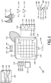
FIG. 1 is a schematic diagram showing, by example, an ultrasound probe, a volume of interest containing blood vessels, and a blood-flow waveform and respective clinical Doppler indices; -
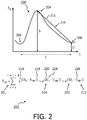
FIG. 2 is a conceptual diagram exemplifying a good pulse cycle and a cycle-series segment quality metric; -
FIG. 3 is a schematic diagram of one possible visual display of segments of pulse cycles, the segments serving as candidates for selection; and -
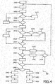
FIG. 4 is a flow chart exemplary of a process for selecting good pulse cycles. - The description of what is proposed herein with regard to automatic pulse cycle selection is preceded with what largely is a review of the Doppler-based probe disclosed in the commonly-assigned patent applications mentioned herein above.
-
FIG. 1 depicts, by way of illustrative and non-limitative example, anultrasound probe 100 and a volume or "volume of interest" 106 containingblood vessels waveform 114, i.e., envelope of a spectrogram, and respectiveclinical Doppler indices - The
probe 100 is implementable as an automatic, handheld, stand-alone, self-contained, ultrasound examination device. It has atransducer housing 120 and ahandle 122. - Within the
transducer housing 120, a non-phased, two-dimensional transducer array 124 is comprised oftransducer elements 126, the number of elements being determined by the scan volume and anatomy. Data acquisition occurs individually byelement 126, although, as discussed in more detail further below, elements are operable concurrently to shorten the total acquisition time period. - As seen in
FIG. 1 by way example, the number ofelements 126 is 32. Thus, with an element size of 10 mm, an approximately 6 cm x 6 cm volume is covered. Flush with afront surface 130 of thehousing 120, are ultrasound-receivingfaces 132 of thetransducer elements 126, the same faces also transmitting, i.e., issuing, ultrasound. - The total of merely 32
elements 126 stands in stark contrast to the much greater number of elements that would be required in conventional medical imaging to cover the same 6 cm x 6 cm volume. - In this regard, electronic focusing for medical imaging, as with a phased-array transducer, requires an inter-element spacing of a ½ wavelength, i.e., ½ λ, or less. Doppler ultrasound for imaging can typically range from between 2 x 10⁶ and 4 x 10⁶ cycles per second (2 to 4 MHz). Ultrasound travels through soft body tissue at a speed of about 1540 meters/second. Wavelength, i.e., λ, is equal to velocity divided by frequency. Here, this is 1540 m/s divided by approximately 2 x 10⁶ cycle/s = 0.8 millimeter. Medical ultrasound imaging for a display would therefore require an inter-element spacing of less than 0.4 mm, and an element surface area of less than (0.4 mm)2 which is less than 0.2 mm2. Therefore, with a small element size on the order of ½ λ, thousands of
elements 126 would be required to build a 2D array that, like the one seen inFIG. 1 , covers a volume of 6 cm by 6 cm. - The spacing (size) of elements in
FIG. 1 is 10 mm, which, as discussed above, would ordinarily be more than 12λ of ultrasound used in examining the volume ofinterest 106 for theblood vessels - More generally, the
elements 126, in accordance with what is proposed herein, are spaced apart by more than ½λ, althoughinter-element spacing 128 may be λ, 2λ or more, as discussed hereinabove. The area of theface 132 is, correspondingly, at least 0.6 square millimeters (mm2), and may be more, such as 10 mm2, 25 mm2, or 100 mm2 as inFIG. 1 . - Advantageously, the
automatic ultrasound device 100 does not rely on display of medical images to reach a diagnosis; but, instead, features an array composed of fewer transducer elements and therefore fewer channels. Thus, cost of production is low, while, by virtue of automatic operation, reliability is maintained. Reliability may even be improved, as when medical examinations must be performed at a quicker pace. The automatic operation also tends to reduce examination time, thereby relieving workload, and making the examination more convenient. - During Doppler data acquisition, the
elements 126 are fired either sequentially, or in one or more groups taking care that the acoustic signal from one element does not significantly affect others that are excited at the same time. For eachelement 126, the receive period lags the transmit period. The Doppler receive gate is correspondingly positioned in the receive period so as to enable sampling from a corresponding depth within the volume ofinterest 106. - On a
back surface 134 of thehousing 120, so as to face the user, are a number of user-interface, input-output panels which include atop panel 136, aleft panel 138 and aright panel 140. An on-off switch 142 and anaudio speaker face 144 are disposed in thetop panel 136. Theleft panel 138 frames a function navigation/actuation button 146, adisplay 148, a Dopplerpower detection indicator 150, fetalheartbeat acquisition indicator 152, a maternalheartbeat acquisition indicator 154, a normal blood-flow indicator 156, and an abnormal blood-flow indicator 158. Theright panel 140 includes three initializing-parameter-entry feedback windows - The
elements 126 of thearray 124 all are operated to image independently. - This stands in contrast to phased arrays for example, which use multiple separate transducer elements collectively to image or steer a beam. In phased arrays, the steering and focusing is performed by appropriately delaying the input and/or output of elements with respect to other elements.
- In accordance with what is proposed herein, the transducer elements of a group are fired simultaneously. The group elements continue imaging concurrently, and independently by element, until expiration of the group's data acquisition time period.
- A device for the imaging by groups is configured not to collectively use any of the
elements 126 to focus, nor to steer, a beam used in the imaging. By way of demonstration, thetransducer elements FIG. 1 each have theirrespective signals signals probe 100 is not implemented for such a protocol, as indicated by the "X" 182 inFIG. 1 . Likewise, on receive, no delay is differentially applied to theelements - The blood-
flow waveform 114 is a graph of Doppler frequency shift versus time and is thereby indicative of blood flow velocity versus time. - Clinical Doppler indices, such as the pulsatility index (PI) 116 and the resistance index (RI) 118 are Doppler angle-independent measures of blood pulsatility. The symbols S, D and C annotating the blood-
flow waveform 114 represent, respectively, the peak systolic frequency shift, the end diastolic frequency shift, and the length of one cardiac cycle. Another commonly-used clinical Doppler index is the systolic/diastolic ratio S/D. The symbols S, D and C are Doppler-spectral-waveform caliper measurements. These and other clinical, or blood-flow, parameters such as the clinical Doppler indices are examples of spectral characteristics of pulsatile flow, based upon which the quality of a cycle can be judged. Another spectral characteristic is the frequency response within a spectral band, which if sufficiently low indicates lack of quality of the cycle. Likewise, if a cycle does not achieve its peak systolic value, or its complete cycle length, within a given time period, it is deemed to lack quality. - The
probe 100 can utilize the above-identified Doppler indices in identifying blood vessels and in assessing normality of blood flow. - The signal processing involved in classifying, and analyzing, a blood vessel 108-112 found by the
probe 100 in the volume ofinterest 106 and more details on the probe and its use are disclosed in the above-mentioned commonly-assigned patent applications. -
FIG. 2 exemplifies agood pulse cycle 200 in a spectrogram of a Doppler signal, and a cycle-seriessegment quality metric 202 for selecting a series of good pulse cycles from a spectrogram. The Doppler signal has been extracted from the carrier frequency, i.e., that of the pulse to be echoed from the blood flow. The extraction is made using a quadrature demodulator. Output from the demodulator is bandpass filtered to remove low frequencies signals that may originate from slow moving structures such as vessel walls and soft tissue, and signals having frequencies above a certain level. The resulting Doppler signal is indicative of the Doppler frequency shift, and of the blood flow velocity. - A typical
good pulse cycle 200, corresponding to a single heart beat, has asignificant peak 204 between twovalleys local peaks 204 orvalleys 208. Thus, eachpulse cycle 200 preferably has asingle peak 204 and asingle valley 208. - Since the rise and fall in frequency shift during the
cycle 200 respectively represent rise and fall in blood flow velocity, a good cycle will exhibit a smooth rise and a smooth fall. The fall part, i.e., from peak to valley, of thecycle 200 undergoes another test. It is checked whether aline 210 joining thepeak 204 and thevalley 208 that immediately follows the peak crosses thewaveform 114 at least once. Acrossing point 211 is shown inFIG. 2 . Lack of such acrossing point 211 indicates that thecycle 200 is not sufficiently representative of the pulsatile blood flow. - Also, some of the spectral information may not be continuously interpretable, as the targeted blood vessel 108-112 may not be within the sample volume due to motion of the patient or sonologist, or the motion of the blood vessel 108-112 itself. Some of the pulse cycles 200 may not be of good quality for interpretation either if the
ultrasound probe 100 does not make proper angle with the blood vessel 108-112 or due to noise from neighboring tissue or in-built electronics. - As a result, portions of the spectrogram may be weak, and seen on screen as faded or missing, indicating that associated frequency samples of the Fast Fourier Transform (FFT) that processes the incoming Doppler signal are low in magnitude. Other types of anomalies that are observed in the shape of the spectrogram profile include weak peak strength,
incomplete cycle 200, absence ofpeak 204 and sharp tall peak. - Based on these considerations, some of the
cycles 200 are initially filtered out. Spectral characteristics of the survivingcycles 200 are extracted and used in scoring segments of five consecutive, surviving cycles. Relying on five cycles is an acceptable clinical practice. The present inventors have empirically found it prudent to select a series ofconsecutive cycles 200. The cycle-seriessegment quality metric 202, shown as Em inFIG. 2 is used for the scoring. It is thesum 201 of fivecycle quality metrics 212, one for each of fiveconsecutive cycles 200. Eachcycle quality metric 212 consists of threeterms 214, although additional terms can be added for medical applications other than obstetrics. Eachterm 214 has abase 216 and anexponent 218. Thebase 216 is a function of what is commonly referred to as "e", the base of the natural logarithm (In). In the example ofFIG. 2 , the function is the identity function. The base 216 can be any value above unity, such as "e" or any larger number. Theexponent 218 is theabsolute value 220 of adeviation 222. Thedeviation 222 is between a Doppler-spectral-waveform caliper measurement 224 on acycle 200 and a median 226 of that measurement over the cycles of the spectrogram that have not been excluded as anomalous. The symbols Si, Ci, and Di represent, the systole, cycle length and diastole of cycle i. Theexponents 218 are the respectiveabsolute values 220 of thedeviations 222 of the systole, cycle length and diastole from thecorresponding medians 226. The median is used as a measure of representative value, because the median is robust to extreme observations and yet serves as a type of average. The exponential nature of theterms 214 ensures that the cost of even asingle cycle 200 deviating from the median 226 incurs a high penalty. The equation for Em is extendable to includeother terms 214 for other medical applications. For instance, a characteristic for the carotid artery is spectral broadening, which is the distance between the peak in the maximum frequency envelope and the peak in the minimum frequency envelope. The maximum frequency envelope is the envelope applied to the spectrogram with respect to the maximum frequencies in blood flow. In particular, due to its viscosity, blood cross-sectionally flows through an artery at different speeds, lagging near the periphery adjacent the artery walls. For cardiac applications such as those relating to the mitral valve, the tricuspid valve and the aortic valve, the characteristics include the isovolume relaxation time, the isovolume acceleration time, the acceleration time in early systole, and the deceleration time in early diastole. In renal applications, spectral broadening of the renal artery can serve as a characteristic. -
FIG. 3 depicts an implementation that includes avisual display 302 ofsegments pulse cycles 200, the segments serving as candidates for selection by the user after having been scored according to Em.An ultrasound probe 308 in this implementation can, but need not, be designed as a standalone device. Theprobe 308 is, wirelessly or by wire, connectable or connected to aprocessor 310 which, in turn, is connected to auser interface 312. Theuser interface 312 has adisplay screen 314 and user actuatable controls 316. A touch-sensitive feature for thescreen 314 can be included among thecontrols 316, as can other navigation and selection devices such as a mouse, buttons, keys slides, knobs and trackballs. - The
display 302 continuously shifts across thedisplay screen 314, as from left to right. Anysegment line 320 between the twosegments cycles 200, or high scoring (and therefore less desirable) segments, have been excluded. The displayedsegments segment screen 314 withcaliper measurements 224 for eachcycle 200 and/or segment scores. When thesegment Doppler parameters cycles 200 in the segment are computed and appear on screen. - As an alternative to the rolling segments, the system can automatically select the segment or segment(s) 304, 306 with the lowest scores, compute the
respective parameters -
FIG. 4 provides, by way of illustrative and non-limitative example, aprocess 400 for selecting good pulse cycles. The user or operator, who may be a clinician, midwife, general practitioner, obstetrician/gynecologist or fetal radiologist, selects a medical application, such as obstetrics, or one or more parameters from a set of parameters (step S402). A Doppler signal is captured during a brief period of time from the received ultrasound (step S404). A spectrogram is computed (step S406). - If sufficient frequency response is lacking over some spectral band of the
current cycle 200 under consideration, as judged from a power threshold (step S408), the current cycle is excluded from selection (step S410). - In either case, if there are
more cycles 200 from the data that has been captured in step S404 (step S412), the next cycle is processed (step S414), and processing returns to step S408 with that next cycle serving as the current cycle. - When there are no
more cycles 200 to consider (step S412), the cycles that have not been excluded collectively constitue a spectrogram having gaps where cycles have been excluded. Thus, the gapped spectrogram typically has one or more time portions in which cycles have not been excluded. An envelope is, by any known and suitable method, computed for the spectrogram time portion(s) that individually comprise five or more consecutive cycles, and thus have the potential for furnishing a segment of five, consecutive, good cycles 200 (step S415). A method for extracting an envelope from a spectrogram is described in the United States Patent No.7,611,467 to Zhang . - Cycle filtering continues. For example,
caliper measurements 224 are made for thecurrent cycle 200, both as to its length of time and the time duration until its peak. - If either
measurement 224 exceeds respective a predetermined range of normality (S416), thecurrent cycle 200 is excluded (step S418). Otherwise, if neither range is exceeded, query is made as to whether more than one peak exists in the current cycle (step S420), and as to whether more than one valley exists in the current cycle (step S422). For either condition, the current cycle is excluded (step S418). - In any event, if more cycles are available for consideration (step S424), processing returns to step S416 with the next cycle serving as the current cycle (step S426).
- When there are no more cycles for the above-described filtering procedure (step S424), the median 226 is calculated over all surviving cycles. This done for each parameter, such a
caliper measurement 224, selected directly or by implication is step S402 (step S428). The calculation is an initial step in computing Em, the cycle-seriessegment quality metric 202, shown inFIG. 2 . - For a
current segment cycles 200 remaining from the above-described filtering, query is made on thedeviation 222 for each cycle of the segment. In particular, query is made as to whether theabsolute value 220 of thedeviation 222 of a parameter from its median 226 exceeds a predetermined deviation threshold. This query is made for each of the selected parameters (step S430). The thresholds may be set so as to detect deviations of 25% or more from therespective median 226. If the deviation threshold is exceeded (step S430), thereby indicating that the current cycle is unworkable, processing shifts cycle-wise past the deviant cycle 200 (step S432). - If, despite the shift, five or more of the
cycles 200 that have survived filtering before step S424 are currently available for forming a segment (S434), return is made to step S430 with thenext segment - If, on the other hand, fewer than five
cycles 200 are available (S434), return is made to step S404. - If the deviation threshold is not exceeded for the
current segment 304, 306 (step S430), the segment is scored to yield the cycle-series segment quality metric 202 (step S436). - If
more segments - Otherwise, if no further scored,
good segments segments caliper measurements 224 and segment scores. Parameters such as Doppler indices are then computed for thesegment good segments segment 304, 306 (step S450), and the segment and parameters are displayed (step S452). The computation may involve averaging results for the fivecycles 200 of the selectedsegment display screen 314. - By virtue of a caliper measurement, operation on a cycle from among the
cycles 200 selected is performed to compute a clinical parameter, this all being done automatically in the innnovative technique. More generally, the computation typically involves such measurements on eachcycle 200, and averaging of results. - Within the
probe - A signal for operating the device, i.e., IC(s), probe or duplex system, in accordance with the techniques proposed herein can be formed internally, formed by varying an electrical current applied to a wire input to the device, or applied to an antenna for wireless transmission of the signal and reception by a receiving antenna of the device.
- A device is configured for examining pulsatile flow, for deriving, based on the examined flow, spectral characteristics and for, based on the derived characteristics, determining which one or more pulse cycles are to be selected as representative of the flow. The cycles selected can be consecutive and amount to a predetermined number of cycles, such as five. The cycles subject to selection may initially be filtered out based on waveform anomalies, with the surviving cycles in a consecutive group of sufficient number being judged based on parameters such as waveform caliper measurements and other types of the characteristics. Good cycles are detected by their lack of variation, with respect to the measured parameters, from each respective, parameter median over the spectrogram cycles not initially filtered. The technique may, according to user selection, take into account additional parameters suited to particular medical application. Uses include correctly identifying an artery by name.
- Although methodology of the present invention can advantageously be applied in providing medical diagnosis for a human or animal subject, the scope of the present invention is not so limited. More broadly, techniques disclosed herein are directed to efficiently finding, and subjecting to improved fluid-flow analysis, vessels in body tissue, in vivo, in vitro or ex vivo.
- What is proposed herein pertains to selecting good cycles of spectral Doppler waveforms, the selected cycles being representative of blood flow, for rendering a clinical diagnosis based on a result of analyzing the selected cycles. The technique is particularly useful for accurately identifying an artery by name as in the commonly-owned patent application entitled "Automatic Blood Vessel Identification by Name" by the same inventors. Applications of the technology proposed herein include carotid and renal arteries screening, anke-brachial index (ABI) measurements for detecting peripheral arterial disease (PAD), transcranial and cardiac examinations, bleed detection in trauma or other hemorrhages, in addition to fetal well-being assessment.
- While the invention has been illustrated and described in detail in the drawings and foregoing description, such illustration and description are to be considered illustrative or exemplary and not restrictive; the invention is not limited to the disclosed embodiments.
- For example, waveform anomalies relating to the shape of a cycle peak can be detected and used in the filtering out of cycles, e.g., step S418.
- A computer program can be stored momentarily, temporarily or for a longer period of time on a suitable computer-readable medium, such as an optical storage medium or a solid-state medium. Such a medium is non-transitory only in the sense of not being a transitory, propagating signal, but includes other forms of computer-readable media such as register memory, processor cache and RAM.
- A single processor or other unit may fulfill the functions of several items recited in the claims. The mere fact that certain measures are recited in mutually different dependent claims does not indicate that a combination of these measures cannot be used to advantage.
Claims (12)
- A device (308) configured for examining pulsatile flow (S404), for deriving, based on the examined flow, a plurality of spectral characteristics and for, based on the derived characteristics, determining which one or more pulse cycles in a spectrogram (114) are to be selected as representative of said flow, said cycles subject to the selection respectively having a plurality of specified parameters, said determining excluding from said selection a cycle, from among said cycles, if any of said specified parameters of said cycle deviates (222), by more than a predetermined amount, from a respective average which the device derives from said spectrogram.
- The device of claim 1, the selected cycles (200) being consecutive.
- The device of claim 1, the selecting choosing a predetermined number of cycles.
- The device of claim 3, said number being five.
- The device of claim 1, comprising a display (314) and further configured for, responsive to said determining, displaying a cycle from among the cycles that have been selected.
- The device of claim 1, further configured for operating on a cycle, from among the cycles that have been selected, to compute a clinical parameter.
- The device of claim 6, comprising a display and further configured for, responsive to the computing, displaying said clinical parameter (116, 118).
- The device of claim 1, comprising a user interface that includes a display, said device being further configured for making the selection by choosing a plurality of segments (304, 306) that each are made up of multiple ones of said cycles and for, on said display, displaying said segments for, via said interface, user selection of a segment from among said segments.
- The device of claim 8, further configured for distinguishing the displayed segments by highlighting them (324, 328).
- The device of claim 1, said average being a median (226).
- The device of claim 1, further configured for filtering out a candidate cycle, from among said cycles subject to the selection, if frequency response in a spectral band of said candidate cycle does not exceed a predetermined threshold.
- A computer readable medium for selecting pulse cycles, said medium comprising a computer program having instructions executable by a processor to cause the device of any of claims 1 to 11 to perform a plurality of acts, among said plurality there being the acts of:
deriving and determining as specified in claim 1.
Applications Claiming Priority (2)
| Application Number | Priority Date | Filing Date | Title |
|---|---|---|---|
| US201161576630P | 2011-12-16 | 2011-12-16 | |
| PCT/IB2012/057033 WO2013088314A1 (en) | 2011-12-16 | 2012-12-06 | Automated doppler pulse cycle selection |
Publications (2)
| Publication Number | Publication Date |
|---|---|
| EP2790588A1 EP2790588A1 (en) | 2014-10-22 |
| EP2790588B1 true EP2790588B1 (en) | 2019-11-13 |
Family
ID=47563558
Family Applications (1)
| Application Number | Title | Priority Date | Filing Date |
|---|---|---|---|
| EP12816350.8A Active EP2790588B1 (en) | 2011-12-16 | 2012-12-06 | Automated doppler pulse cycle selection |
Country Status (8)
| Country | Link |
|---|---|
| US (1) | US20140358000A1 (en) |
| EP (1) | EP2790588B1 (en) |
| JP (1) | JP6114757B2 (en) |
| CN (1) | CN104114101B (en) |
| BR (1) | BR112014014413B1 (en) |
| IN (1) | IN2014CN04916A (en) |
| RU (1) | RU2674241C2 (en) |
| WO (1) | WO2013088314A1 (en) |
Families Citing this family (16)
| Publication number | Priority date | Publication date | Assignee | Title |
|---|---|---|---|---|
| US11678808B2 (en) | 2009-03-13 | 2023-06-20 | Bluedop Medical, Ltd. | Haemodynamic data estimation apparatus and method of use |
| GB0904435D0 (en) | 2009-03-13 | 2009-04-29 | King David H | Haemodynamic data estimation |
| BR112014014288A2 (en) | 2011-12-16 | 2017-06-13 | Koninklijke Philips Nv | computer readable device and media for anatomical identification of a blood vessel |
| JP6297150B2 (en) * | 2013-07-24 | 2018-03-20 | コーニンクレッカ フィリップス エヌ ヴェKoninklijke Philips N.V. | A method for aligning spatially different subvolumes of vascular ultrasound data |
| CN105491957B (en) * | 2013-07-24 | 2019-03-12 | 皇家飞利浦有限公司 | Non-imaged two-dimensional array probe and system for classifying to carotid artery stenosis |
| CA2939353C (en) | 2014-02-25 | 2018-01-02 | Icu Medical, Inc. | Patient monitoring system with gatekeeper signal |
| EP2989986B1 (en) * | 2014-09-01 | 2019-12-18 | Samsung Medison Co., Ltd. | Ultrasound diagnosis apparatus and method of operating the same |
| JP6674553B2 (en) | 2015-10-19 | 2020-04-01 | アイシーユー・メディカル・インコーポレーテッド | Hemodynamic monitoring system with detachable display unit |
| US11660063B2 (en) * | 2015-11-18 | 2023-05-30 | Bluedop Medical, Ltd. | System for determining peripheral artery disease and method of use |
| EP3189776A1 (en) * | 2016-01-08 | 2017-07-12 | Koninklijke Philips N.V. | An apparatus and method for generating fetal heart rate data |
| US11617563B2 (en) * | 2016-06-07 | 2023-04-04 | Viewcare Technologies 1 Aps | Method and system for measuring a central pulse wave velocity in a pregnant woman |
| US11717255B2 (en) | 2016-08-05 | 2023-08-08 | Cimon Medical As | Ultrasound blood-flow monitoring |
| CN110072466B (en) * | 2016-12-15 | 2022-07-19 | 皇家飞利浦有限公司 | Prenatal ultrasound imaging |
| FR3060966B1 (en) * | 2016-12-23 | 2019-05-31 | Azoth Systems | DEVICE FOR MEASURING BLOOD FLOW |
| US11607198B2 (en) | 2018-01-02 | 2023-03-21 | Bluedop Medical, Ltd. | System for determining peripheral artery disease and method of use |
| CN111801052A (en) * | 2018-02-07 | 2020-10-20 | 挪威科技大学 | Ultrasonic blood flow monitoring |
Family Cites Families (11)
| Publication number | Priority date | Publication date | Assignee | Title |
|---|---|---|---|---|
| US4476874A (en) * | 1982-06-01 | 1984-10-16 | Sri International | Ultrasonic imaging with volume flow measuring method and apparatus |
| US5628321A (en) * | 1995-12-18 | 1997-05-13 | Diasonics Ultrasound, Inc. | Processing velocity information in an ultrasonic system |
| US6423006B1 (en) * | 2000-01-21 | 2002-07-23 | Siemens Medical Solutions Usa, Inc. | Method and apparatus for automatic vessel tracking in ultrasound systems |
| WO2007085999A1 (en) * | 2006-01-27 | 2007-08-02 | Koninklijke Philips Electronics N.V. | Automatic ultrasonic doppler measurements |
| CN101378699B (en) * | 2006-02-03 | 2012-06-20 | 皇家飞利浦电子股份有限公司 | Ultrasonic method and apparatus for measuring or detecting flow behavior of a non-sinusoidal periodicity |
| US8323198B2 (en) * | 2007-01-29 | 2012-12-04 | Siemens Medical Solutions Usa, Inc. | Spatial and temporal alignment for volume rendering in medical diagnostic ultrasound |
| RU2010106996A (en) * | 2007-07-26 | 2011-09-10 | Конинклейке Филипс Электроникс, Н.В. (Nl) | SYSTEMS AND METHODS FOR AUTOMATED SELECTION OF IMAGES IN THE SYSTEMS OF ULTRASONIC VISUALIZATION WITH DOPPLER MODE |
| EP2303131B1 (en) * | 2008-06-26 | 2015-04-22 | Verasonics, Inc. | High frame rate quantitative doppler flow imaging using unfocused transmit beams |
| RU2407008C1 (en) * | 2009-06-04 | 2010-12-20 | Федеральное государственное учреждение "Ивановский научно-исследовательский институт материнства и детства имени В.Н. Городкова Федерального агентства по высокотехнологичной медицинской помощи" | Method of morphological diagnostics of severity degree of gestosis |
| US8394025B2 (en) * | 2009-06-26 | 2013-03-12 | Uab Vittamed | Method and apparatus for determining the absolute value of intracranial pressure |
| WO2012085788A2 (en) * | 2010-12-22 | 2012-06-28 | Koninklijke Philips Electronics N.V. | Automated doppler velocimetry using a low-cost transducer. |
-
2012
- 2012-12-06 JP JP2014546691A patent/JP6114757B2/en active Active
- 2012-12-06 US US14/364,360 patent/US20140358000A1/en not_active Abandoned
- 2012-12-06 IN IN4916CHN2014 patent/IN2014CN04916A/en unknown
- 2012-12-06 BR BR112014014413-3A patent/BR112014014413B1/en active IP Right Grant
- 2012-12-06 WO PCT/IB2012/057033 patent/WO2013088314A1/en active Application Filing
- 2012-12-06 EP EP12816350.8A patent/EP2790588B1/en active Active
- 2012-12-06 CN CN201280069732.5A patent/CN104114101B/en active Active
- 2012-12-06 RU RU2014129043A patent/RU2674241C2/en active
Non-Patent Citations (1)
| Title |
|---|
| None * |
Also Published As
| Publication number | Publication date |
|---|---|
| BR112014014413A2 (en) | 2017-06-13 |
| CN104114101A (en) | 2014-10-22 |
| US20140358000A1 (en) | 2014-12-04 |
| CN104114101B (en) | 2016-08-24 |
| WO2013088314A1 (en) | 2013-06-20 |
| JP2015500120A (en) | 2015-01-05 |
| IN2014CN04916A (en) | 2015-09-18 |
| EP2790588A1 (en) | 2014-10-22 |
| BR112014014413B1 (en) | 2022-09-06 |
| RU2674241C2 (en) | 2018-12-05 |
| JP6114757B2 (en) | 2017-04-12 |
| RU2014129043A (en) | 2016-02-10 |
Similar Documents
| Publication | Publication Date | Title |
|---|---|---|
| EP2790588B1 (en) | Automated doppler pulse cycle selection | |
| EP2790585B1 (en) | Automatic blood vessel identification by name | |
| EP2654572B1 (en) | Automated doppler velocimetry using a low-cost transducer | |
| US9579078B2 (en) | Excitation schemes for low-cost transducer arrays | |
| US20150080730A1 (en) | Ultrasonic diagnostic apparatus, medical image processing apparatus, and medical image processing method | |
| WO2018134726A1 (en) | Method and apparatus to characterise non-invasively images containing venous blood vessels | |
| JP2006068526A (en) | Three-dimensional detection of flat surface of ventricle and atrium cordis | |
| JP2008183063A (en) | Medical image diagnostic apparatus, medical image display device and program | |
| JP7102630B2 (en) | Fetal sonication unit for separating heartbeat signals | |
| JP2010200844A (en) | Ultrasonic diagnostic apparatus and data processing program of the same | |
| Joseph et al. | ARTSENS® Pen: A portable, image-free device for automated evaluation of vascular stiffness | |
| CN115299986A (en) | Ultrasonic imaging equipment and ultrasonic inspection method thereof | |
| WO2020037673A1 (en) | Ultrasound elastography device and elastic image processing method | |
| JP5443781B2 (en) | Ultrasonic diagnostic equipment | |
| JP4373718B2 (en) | Ultrasound diagnostic device with blood vessel measurement function | |
| CN113727654B (en) | Fetal ultrasonic processing unit for separating heart rate signals | |
| WO2007072720A1 (en) | Diagnostic imaging apparatus for medical use and method of identifying biological tissue | |
| CN117159021A (en) | Ultrasonic imaging system and ultrasonic imaging method |
Legal Events
| Date | Code | Title | Description |
|---|---|---|---|
| PUAI | Public reference made under article 153(3) epc to a published international application that has entered the european phase |
Free format text: ORIGINAL CODE: 0009012 |
|
| 17P | Request for examination filed |
Effective date: 20140716 |
|
| AK | Designated contracting states |
Kind code of ref document: A1 Designated state(s): AL AT BE BG CH CY CZ DE DK EE ES FI FR GB GR HR HU IE IS IT LI LT LU LV MC MK MT NL NO PL PT RO RS SE SI SK SM TR |
|
| DAX | Request for extension of the european patent (deleted) | ||
| STAA | Information on the status of an ep patent application or granted ep patent |
Free format text: STATUS: EXAMINATION IS IN PROGRESS |
|
| 17Q | First examination report despatched |
Effective date: 20181219 |
|
| GRAP | Despatch of communication of intention to grant a patent |
Free format text: ORIGINAL CODE: EPIDOSNIGR1 |
|
| STAA | Information on the status of an ep patent application or granted ep patent |
Free format text: STATUS: GRANT OF PATENT IS INTENDED |
|
| INTG | Intention to grant announced |
Effective date: 20190603 |
|
| GRAS | Grant fee paid |
Free format text: ORIGINAL CODE: EPIDOSNIGR3 |
|
| GRAA | (expected) grant |
Free format text: ORIGINAL CODE: 0009210 |
|
| STAA | Information on the status of an ep patent application or granted ep patent |
Free format text: STATUS: THE PATENT HAS BEEN GRANTED |
|
| AK | Designated contracting states |
Kind code of ref document: B1 Designated state(s): AL AT BE BG CH CY CZ DE DK EE ES FI FR GB GR HR HU IE IS IT LI LT LU LV MC MK MT NL NO PL PT RO RS SE SI SK SM TR |
|
| REG | Reference to a national code |
Ref country code: CH Ref legal event code: EP Ref country code: AT Ref legal event code: REF Ref document number: 1200842 Country of ref document: AT Kind code of ref document: T Effective date: 20191115 |
|
| REG | Reference to a national code |
Ref country code: DE Ref legal event code: R096 Ref document number: 602012065695 Country of ref document: DE |
|
| REG | Reference to a national code |
Ref country code: IE Ref legal event code: FG4D |
|
| REG | Reference to a national code |
Ref country code: DE Ref legal event code: R084 Ref document number: 602012065695 Country of ref document: DE |
|
| REG | Reference to a national code |
Ref country code: GB Ref legal event code: 746 Effective date: 20200210 |
|
| RAP2 | Party data changed (patent owner data changed or rights of a patent transferred) |
Owner name: KONINKLIJKE PHILIPS N.V. |
|
| REG | Reference to a national code |
Ref country code: NL Ref legal event code: MP Effective date: 20191113 |
|
| REG | Reference to a national code |
Ref country code: LT Ref legal event code: MG4D |
|
| PG25 | Lapsed in a contracting state [announced via postgrant information from national office to epo] |
Ref country code: FI Free format text: LAPSE BECAUSE OF FAILURE TO SUBMIT A TRANSLATION OF THE DESCRIPTION OR TO PAY THE FEE WITHIN THE PRESCRIBED TIME-LIMIT Effective date: 20191113 Ref country code: BG Free format text: LAPSE BECAUSE OF FAILURE TO SUBMIT A TRANSLATION OF THE DESCRIPTION OR TO PAY THE FEE WITHIN THE PRESCRIBED TIME-LIMIT Effective date: 20200213 Ref country code: SE Free format text: LAPSE BECAUSE OF FAILURE TO SUBMIT A TRANSLATION OF THE DESCRIPTION OR TO PAY THE FEE WITHIN THE PRESCRIBED TIME-LIMIT Effective date: 20191113 Ref country code: LV Free format text: LAPSE BECAUSE OF FAILURE TO SUBMIT A TRANSLATION OF THE DESCRIPTION OR TO PAY THE FEE WITHIN THE PRESCRIBED TIME-LIMIT Effective date: 20191113 Ref country code: NL Free format text: LAPSE BECAUSE OF FAILURE TO SUBMIT A TRANSLATION OF THE DESCRIPTION OR TO PAY THE FEE WITHIN THE PRESCRIBED TIME-LIMIT Effective date: 20191113 Ref country code: PT Free format text: LAPSE BECAUSE OF FAILURE TO SUBMIT A TRANSLATION OF THE DESCRIPTION OR TO PAY THE FEE WITHIN THE PRESCRIBED TIME-LIMIT Effective date: 20200313 Ref country code: NO Free format text: LAPSE BECAUSE OF FAILURE TO SUBMIT A TRANSLATION OF THE DESCRIPTION OR TO PAY THE FEE WITHIN THE PRESCRIBED TIME-LIMIT Effective date: 20200213 Ref country code: PL Free format text: LAPSE BECAUSE OF FAILURE TO SUBMIT A TRANSLATION OF THE DESCRIPTION OR TO PAY THE FEE WITHIN THE PRESCRIBED TIME-LIMIT Effective date: 20191113 Ref country code: GR Free format text: LAPSE BECAUSE OF FAILURE TO SUBMIT A TRANSLATION OF THE DESCRIPTION OR TO PAY THE FEE WITHIN THE PRESCRIBED TIME-LIMIT Effective date: 20200214 Ref country code: LT Free format text: LAPSE BECAUSE OF FAILURE TO SUBMIT A TRANSLATION OF THE DESCRIPTION OR TO PAY THE FEE WITHIN THE PRESCRIBED TIME-LIMIT Effective date: 20191113 Ref country code: ES Free format text: LAPSE BECAUSE OF FAILURE TO SUBMIT A TRANSLATION OF THE DESCRIPTION OR TO PAY THE FEE WITHIN THE PRESCRIBED TIME-LIMIT Effective date: 20191113 |
|
| PG25 | Lapsed in a contracting state [announced via postgrant information from national office to epo] |
Ref country code: IS Free format text: LAPSE BECAUSE OF FAILURE TO SUBMIT A TRANSLATION OF THE DESCRIPTION OR TO PAY THE FEE WITHIN THE PRESCRIBED TIME-LIMIT Effective date: 20200313 Ref country code: HR Free format text: LAPSE BECAUSE OF FAILURE TO SUBMIT A TRANSLATION OF THE DESCRIPTION OR TO PAY THE FEE WITHIN THE PRESCRIBED TIME-LIMIT Effective date: 20191113 Ref country code: RS Free format text: LAPSE BECAUSE OF FAILURE TO SUBMIT A TRANSLATION OF THE DESCRIPTION OR TO PAY THE FEE WITHIN THE PRESCRIBED TIME-LIMIT Effective date: 20191113 |
|
| PG25 | Lapsed in a contracting state [announced via postgrant information from national office to epo] |
Ref country code: AL Free format text: LAPSE BECAUSE OF FAILURE TO SUBMIT A TRANSLATION OF THE DESCRIPTION OR TO PAY THE FEE WITHIN THE PRESCRIBED TIME-LIMIT Effective date: 20191113 |
|
| PG25 | Lapsed in a contracting state [announced via postgrant information from national office to epo] |
Ref country code: DK Free format text: LAPSE BECAUSE OF FAILURE TO SUBMIT A TRANSLATION OF THE DESCRIPTION OR TO PAY THE FEE WITHIN THE PRESCRIBED TIME-LIMIT Effective date: 20191113 Ref country code: EE Free format text: LAPSE BECAUSE OF FAILURE TO SUBMIT A TRANSLATION OF THE DESCRIPTION OR TO PAY THE FEE WITHIN THE PRESCRIBED TIME-LIMIT Effective date: 20191113 Ref country code: RO Free format text: LAPSE BECAUSE OF FAILURE TO SUBMIT A TRANSLATION OF THE DESCRIPTION OR TO PAY THE FEE WITHIN THE PRESCRIBED TIME-LIMIT Effective date: 20191113 Ref country code: CZ Free format text: LAPSE BECAUSE OF FAILURE TO SUBMIT A TRANSLATION OF THE DESCRIPTION OR TO PAY THE FEE WITHIN THE PRESCRIBED TIME-LIMIT Effective date: 20191113 |
|
| REG | Reference to a national code |
Ref country code: CH Ref legal event code: PL |
|
| REG | Reference to a national code |
Ref country code: DE Ref legal event code: R097 Ref document number: 602012065695 Country of ref document: DE |
|
| REG | Reference to a national code |
Ref country code: AT Ref legal event code: MK05 Ref document number: 1200842 Country of ref document: AT Kind code of ref document: T Effective date: 20191113 |
|
| REG | Reference to a national code |
Ref country code: BE Ref legal event code: MM Effective date: 20191231 |
|
| PG25 | Lapsed in a contracting state [announced via postgrant information from national office to epo] |
Ref country code: SK Free format text: LAPSE BECAUSE OF FAILURE TO SUBMIT A TRANSLATION OF THE DESCRIPTION OR TO PAY THE FEE WITHIN THE PRESCRIBED TIME-LIMIT Effective date: 20191113 Ref country code: SM Free format text: LAPSE BECAUSE OF FAILURE TO SUBMIT A TRANSLATION OF THE DESCRIPTION OR TO PAY THE FEE WITHIN THE PRESCRIBED TIME-LIMIT Effective date: 20191113 Ref country code: MC Free format text: LAPSE BECAUSE OF FAILURE TO SUBMIT A TRANSLATION OF THE DESCRIPTION OR TO PAY THE FEE WITHIN THE PRESCRIBED TIME-LIMIT Effective date: 20191113 |
|
| PLBE | No opposition filed within time limit |
Free format text: ORIGINAL CODE: 0009261 |
|
| STAA | Information on the status of an ep patent application or granted ep patent |
Free format text: STATUS: NO OPPOSITION FILED WITHIN TIME LIMIT |
|
| 26N | No opposition filed |
Effective date: 20200814 |
|
| PG25 | Lapsed in a contracting state [announced via postgrant information from national office to epo] |
Ref country code: IE Free format text: LAPSE BECAUSE OF NON-PAYMENT OF DUE FEES Effective date: 20191206 Ref country code: LU Free format text: LAPSE BECAUSE OF NON-PAYMENT OF DUE FEES Effective date: 20191206 |
|
| PG25 | Lapsed in a contracting state [announced via postgrant information from national office to epo] |
Ref country code: CH Free format text: LAPSE BECAUSE OF NON-PAYMENT OF DUE FEES Effective date: 20191231 Ref country code: AT Free format text: LAPSE BECAUSE OF FAILURE TO SUBMIT A TRANSLATION OF THE DESCRIPTION OR TO PAY THE FEE WITHIN THE PRESCRIBED TIME-LIMIT Effective date: 20191113 Ref country code: LI Free format text: LAPSE BECAUSE OF NON-PAYMENT OF DUE FEES Effective date: 20191231 Ref country code: SI Free format text: LAPSE BECAUSE OF FAILURE TO SUBMIT A TRANSLATION OF THE DESCRIPTION OR TO PAY THE FEE WITHIN THE PRESCRIBED TIME-LIMIT Effective date: 20191113 Ref country code: BE Free format text: LAPSE BECAUSE OF NON-PAYMENT OF DUE FEES Effective date: 20191231 |
|
| PG25 | Lapsed in a contracting state [announced via postgrant information from national office to epo] |
Ref country code: IT Free format text: LAPSE BECAUSE OF FAILURE TO SUBMIT A TRANSLATION OF THE DESCRIPTION OR TO PAY THE FEE WITHIN THE PRESCRIBED TIME-LIMIT Effective date: 20191113 |
|
| PG25 | Lapsed in a contracting state [announced via postgrant information from national office to epo] |
Ref country code: CY Free format text: LAPSE BECAUSE OF FAILURE TO SUBMIT A TRANSLATION OF THE DESCRIPTION OR TO PAY THE FEE WITHIN THE PRESCRIBED TIME-LIMIT Effective date: 20191113 |
|
| PG25 | Lapsed in a contracting state [announced via postgrant information from national office to epo] |
Ref country code: MT Free format text: LAPSE BECAUSE OF FAILURE TO SUBMIT A TRANSLATION OF THE DESCRIPTION OR TO PAY THE FEE WITHIN THE PRESCRIBED TIME-LIMIT Effective date: 20191113 Ref country code: HU Free format text: LAPSE BECAUSE OF FAILURE TO SUBMIT A TRANSLATION OF THE DESCRIPTION OR TO PAY THE FEE WITHIN THE PRESCRIBED TIME-LIMIT; INVALID AB INITIO Effective date: 20121206 |
|
| PG25 | Lapsed in a contracting state [announced via postgrant information from national office to epo] |
Ref country code: TR Free format text: LAPSE BECAUSE OF FAILURE TO SUBMIT A TRANSLATION OF THE DESCRIPTION OR TO PAY THE FEE WITHIN THE PRESCRIBED TIME-LIMIT Effective date: 20191113 |
|
| PG25 | Lapsed in a contracting state [announced via postgrant information from national office to epo] |
Ref country code: MK Free format text: LAPSE BECAUSE OF FAILURE TO SUBMIT A TRANSLATION OF THE DESCRIPTION OR TO PAY THE FEE WITHIN THE PRESCRIBED TIME-LIMIT Effective date: 20191113 |
|
| PGFP | Annual fee paid to national office [announced via postgrant information from national office to epo] |
Ref country code: DE Payment date: 20220628 Year of fee payment: 11 |
|
| PGFP | Annual fee paid to national office [announced via postgrant information from national office to epo] |
Ref country code: GB Payment date: 20231219 Year of fee payment: 12 |
|
| PGFP | Annual fee paid to national office [announced via postgrant information from national office to epo] |
Ref country code: FR Payment date: 20231226 Year of fee payment: 12 |