EP2790309A1 - Linearantrieb und mundhygienevorrichtung - Google Patents
Linearantrieb und mundhygienevorrichtung Download PDFInfo
- Publication number
- EP2790309A1 EP2790309A1 EP12854814.6A EP12854814A EP2790309A1 EP 2790309 A1 EP2790309 A1 EP 2790309A1 EP 12854814 A EP12854814 A EP 12854814A EP 2790309 A1 EP2790309 A1 EP 2790309A1
- Authority
- EP
- European Patent Office
- Prior art keywords
- linear actuator
- output shaft
- weight
- movable element
- magnetic
- Prior art date
- Legal status (The legal status is an assumption and is not a legal conclusion. Google has not performed a legal analysis and makes no representation as to the accuracy of the status listed.)
- Granted
Links
- 230000008878 coupling Effects 0.000 claims description 25
- 238000010168 coupling process Methods 0.000 claims description 25
- 238000005859 coupling reaction Methods 0.000 claims description 25
- 210000000214 mouth Anatomy 0.000 claims description 15
- 238000004519 manufacturing process Methods 0.000 description 10
- 230000008901 benefit Effects 0.000 description 9
- 230000004308 accommodation Effects 0.000 description 8
- 230000003247 decreasing effect Effects 0.000 description 6
- 230000005484 gravity Effects 0.000 description 6
- 238000004804 winding Methods 0.000 description 6
- 230000009467 reduction Effects 0.000 description 5
- 230000001680 brushing effect Effects 0.000 description 3
- 238000004140 cleaning Methods 0.000 description 2
- 239000013013 elastic material Substances 0.000 description 2
- 239000012212 insulator Substances 0.000 description 2
- 239000000696 magnetic material Substances 0.000 description 2
- 239000000463 material Substances 0.000 description 2
- 239000011347 resin Substances 0.000 description 2
- 229920005989 resin Polymers 0.000 description 2
- 229910000831 Steel Inorganic materials 0.000 description 1
- 230000006835 compression Effects 0.000 description 1
- 238000007906 compression Methods 0.000 description 1
- 230000007423 decrease Effects 0.000 description 1
- 238000010586 diagram Methods 0.000 description 1
- 230000005489 elastic deformation Effects 0.000 description 1
- 239000002184 metal Substances 0.000 description 1
- 230000004048 modification Effects 0.000 description 1
- 238000012986 modification Methods 0.000 description 1
- 230000010355 oscillation Effects 0.000 description 1
- 230000001846 repelling effect Effects 0.000 description 1
- 239000010959 steel Substances 0.000 description 1
- 239000000758 substrate Substances 0.000 description 1
Images


Classifications
-
- A—HUMAN NECESSITIES
- A61—MEDICAL OR VETERINARY SCIENCE; HYGIENE
- A61C—DENTISTRY; APPARATUS OR METHODS FOR ORAL OR DENTAL HYGIENE
- A61C17/00—Devices for cleaning, polishing, rinsing or drying teeth, teeth cavities or prostheses; Saliva removers; Dental appliances for receiving spittle
- A61C17/16—Power-driven cleaning or polishing devices
- A61C17/22—Power-driven cleaning or polishing devices with brushes, cushions, cups, or the like
- A61C17/225—Handles or details thereof
-
- A—HUMAN NECESSITIES
- A61—MEDICAL OR VETERINARY SCIENCE; HYGIENE
- A61C—DENTISTRY; APPARATUS OR METHODS FOR ORAL OR DENTAL HYGIENE
- A61C17/00—Devices for cleaning, polishing, rinsing or drying teeth, teeth cavities or prostheses; Saliva removers; Dental appliances for receiving spittle
- A61C17/16—Power-driven cleaning or polishing devices
- A61C17/22—Power-driven cleaning or polishing devices with brushes, cushions, cups, or the like
- A61C17/32—Power-driven cleaning or polishing devices with brushes, cushions, cups, or the like reciprocating or oscillating
- A61C17/34—Power-driven cleaning or polishing devices with brushes, cushions, cups, or the like reciprocating or oscillating driven by electric motor
- A61C17/3409—Power-driven cleaning or polishing devices with brushes, cushions, cups, or the like reciprocating or oscillating driven by electric motor characterized by the movement of the brush body
- A61C17/3481—Vibrating brush body, e.g. by using eccentric weights
-
- H—ELECTRICITY
- H02—GENERATION; CONVERSION OR DISTRIBUTION OF ELECTRIC POWER
- H02K—DYNAMO-ELECTRIC MACHINES
- H02K33/00—Motors with reciprocating, oscillating or vibrating magnet, armature or coil system
- H02K33/16—Motors with reciprocating, oscillating or vibrating magnet, armature or coil system with polarised armatures moving in alternate directions by reversal or energisation of a single coil system
-
- A—HUMAN NECESSITIES
- A46—BRUSHWARE
- A46B—BRUSHES
- A46B15/00—Other brushes; Brushes with additional arrangements
- A46B15/0002—Arrangements for enhancing monitoring or controlling the brushing process
- A46B15/0004—Arrangements for enhancing monitoring or controlling the brushing process with a controlling means
- A46B15/0012—Arrangements for enhancing monitoring or controlling the brushing process with a controlling means with a pressure controlling device
Definitions
- the present invention relates to an oscillation type linear actuator, which includes a movable unit that linearly reciprocates, and an oral cavity hygiene device.
- Patent document 1 describes a linear actuator used as a drive source for an oral cavity hygiene device such as an electric toothbrush.
- the linear actuator includes a stator, an output shaft, and a movable element.
- the stator is cylindrical and includes an electromagnet.
- the output shaft is arranged at the inner side of the stator.
- the movable element is cylindrical and formed by a magnetic body fixed to the circumferential surface of the output shaft. Current is supplied to the electromagnet to reciprocate the movable element and the output shaft in the axial direction of the output shaft.
- Patent document 2 describes a linear actuator that reduces excessive vibration generated when a movable element reciprocates.
- the linear actuator includes a movable element, which reciprocates on an output shaft, and a weight, which is separate from the movable element and which reciprocates on the same output shaft. The reciprocation of the weight absorbs or offsets the vibration generated when the movable element reciprocates This reduces vibration.
- the movable element and the weight are arranged coaxially with the output shaft. This enlarges the linear actuator in the axial direction of the output shaft.
- a linear actuator includes a permanent magnet and an electromagnet arranged facing each other with a gap in between.
- a plurality of movable elements arranged in parallel include first and second movable elements that are adjacent to each other and reciprocated in opposite phases when the electromagnet is supplied with current.
- An output shaft is arranged on at least one of the movable elements. The output shaft includes an axial direction in a reciprocation direction of the movable elements.
- the output shaft is arranged on an end of the first movable element.
- the second movable element is connected to a weight.
- the output shaft and the weight are arranged on opposite sides in the reciprocation direction and reciprocated in opposite phases.
- the output shaft is arranged on one end of the first movable element.
- the second movable element is connected to a weight.
- the output shaft and the weight are arranged on the same side in the reciprocation direction and reciprocated in opposite phases.
- the output shaft is arranged on one end of the first movable element.
- the second movable element is connected to a weight.
- the weight is arranged to partially or entirely face a side portion of the linear actuator in a direction orthogonal to the reciprocation direction.
- the output shaft and the weight are reciprocated in opposite phases.
- One example of the actuator further includes an elastic coupling member that couples one end of the first movable element and one end of the second movable element.
- One example of the actuator further includes a connection member that connects the weight and the second movable element.
- the weight is a bent plate.
- the output shaft is arranged in a central portion of the linear actuator on a plane orthogonal to the reciprocation direction
- One example of the actuator includes an L-shaped connection member that couples the output shaft and the first movable element
- the first movable element is a magnetic block including the permanent magnet and a back yoke fixed to the permanent magnet A portion connecting the output shaft and the magnetic block is formed integrally with the back yoke
- One example of the actuator includes a holding member that holds the electromagnet and the permanent magnet so that the electromagnet and the permanent magnet face each other with the gap in between
- the output shaft is inserted through a through hole of the holding member and coupled to the first movable element
- An oral cavity hygiene device includes the linear actuator and a driven body used for oral cavity hygiene and connected to the output shaft
- the linear actuator is arranged so that a direction in which an attraction force acts between the electromagnet and the permanent magnet of the linear actuator is opposite to a direction in which a pushing force acts on the driven body during use of the oral cavity hygiene device
- the linear actuator includes a holding member
- the holding member includes opposing plate springs that hold the electromagnet and the permanent magnet so that the electromagnet and the permanent magnet face each other with the gap in between
- the present invention allows for reduction in the size of a linear actuator including a plurality of movable units
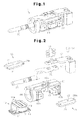
- a linear actuator 1 according to a first embodiment of the present invention will now be described with reference to Figs 1 to 4
- the linear actuator 1 of the first embodiment is used in an electric toothbrush, which is one example of an oral cavity hygiene device.
- the linear actuator 1 includes an electromagnetic block 10, which functions as a stator, a magnetic block 20, which functions as a movable element, and an output shaft 30, which reciprocates in an axial direction through cooperation of the blocks.
- the electromagnetic block 10 includes a core and a winding 12.
- the core 11 is comb teeth shaped and includes three teeth 11a.
- the winding 12 is wound around the middle tooth by way of an insulator 13.
- the core 11 may be a sintered body of a magnetic material or a laminated body of steel plates.
- the core 11 and the winding 12 are insulated by the insulator 13.
- the electromagnetic block 10 functions as an electromagnet when current is supplied to the winding 12.
- a fixing member 14 for fixing the linear actuator 1 to an electric toothbrush housing 70, which will be described later, is attached to the electromagnetic block 10.
- the magnetic block 20 includes a permanent magnet 21 and a back yoke 22, which is made from a magnetic material and adhered and fixed to the permanent magnet 21.
- the linear actuator 1 of the first embodiment includes two magnetic blocks 20a and 20b, which function as the magnetic block 20.
- the electromagnetic block 10 and the magnetic blocks 20a and 20b are held by a holding member 40 so that the electromagnetic block 10 and the permanent magnet 21 face each other spaced apart by a predetermined interval.
- the holding member 40 includes an electromagnetic block accommodation portion 41, which accommodates the electromagnetic block 10, and magnetic block accommodation portions 42a and 42b, which accommodate the magnetic blocks 20a and 20b.
- the electromagnetic block 10 is accommodated in the electromagnetic block accommodation portion 41 so that the teeth 11a of the core 11 face the inner side and the fixing member 14 faces the outer side.
- the magnetic blocks 20a and 20b are respectively accommodated in the magnetic block accommodation portions 42a and 42b of the holding member 40 with the permanent magnet 21 facing the teeth 11a of the core 11 and the magnetic block 20a and the magnetic block 20b arranged next to each other.
- the holding member 40 includes plate spring units 43 and 44 When the electromagnetic block 10 and the magnetic block 20a are each resiliently supported by the plate spring units 43a and 43b, a gap is formed and kept between the electromagnetic block 10 and the magnetic block 20a. In the same manner, when the electromagnetic block 10 and the magnetic block 20b are each resiliently supported by the plate spring units 43a and 43b, the gap is formed and kept between the electromagnetic block 10 and the magnetic block 20b.
- each of the plate spring units 43a and 43b is formed by two sheets of plate springs.
- a ring-shaped coupling portion 44 couples one end of the magnetic block accommodation portion 42a and one end of the magnetic block accommodation portion 42b.
- the holding member 40 which includes the electromagnetic block accommodation portion 41, the magnetic block accommodation portions 42a and 42b, and the plate spring units 43a and 43b, is a resin component formed integrally with the coupling portion 44.
- a material having small stretchability is suitable for the holding member 40, and an elastic material is suitable for the coupling portion 44.
- An output shaft connection member 50 couples the magnetic block 20a to the output shaft 30.
- Bolts 51 fasten and fix one end of the output shaft connection member 50 to the back yoke 22 of the magnetic block 20a with the holding member 40 located in between.
- the other end of the output shaft connection member 50 is coupled to the output shaft 30.
- the output shaft connection member 31 is L-shaped, for example.
- the magnetic block 20b is coupled to a weight 60 by a weight connection member 52.
- Bolts 53 fasten and fix one end of the weight connection member 52 to the back yoke 22 of the magnetic block 20b with the holding member 40 located in between
- a bolt 54 fixes the other end of the weight connection member 52 to the weight 60
- the weight 60 may be cuboidal-shaped, for example.
- the electromagnetic block 10 functions as the stator and is fixed to the housing 70 of the electric toothbrush.
- the magnetic blocks 20a and 20b function as movable elements.
- each of the magnetic blocks 20a and 20b are reciprocated by the magnetic thrust (attracting force and repelling force) generated between the permanent magnet 21 and the core 11, which becomes the magnetic pole of the electromagnet.
- the holding member 40 restricts the reciprocation direction of the magnetic blocks 20a and 20b.
- the magnetic blocks 20a and 20b use the elastic deformation of the holding member 40 and reciprocate along the opposing surfaces of the electromagnetic block 10 between the plate spring units 43a and 43b.
- the magnetic block 20a and the magnetic block 20b are arranged parallel to each other in a direction orthogonal to the reciprocation direction of the magnetic blocks 20a and 20b.
- the directions and the like of the permanent magnet 21 of each magnetic block are set so that the magnetic block 20a and the magnetic block 20b are reciprocated in opposite phases.
- the output shaft 30 is coupled to the magnetic block 20a so that the axial direction of the output shaft 30 is the same as the reciprocation direction of the magnetic blocks 20a and 20b.
- the weight 60 is coupled to the magnetic block 20b at the side opposite to the output shaft 30 in the axial direction of the output shaft 30.
- the holding member 40 couples the output shaft 30 and the weight 60 to the coupling portion 44.
- the coupling portion 44 may be formed at a portion located toward the distal end of the linear actuator 1 from the magnetic blocks 20a and 20b.
- the L-shaped output shaft connection member 50 arranges the output shaft 30 in the central portion of the linear actuator 1 in a plane orthogonal to the reciprocation direction of the magnetic blocks 20a and 20b.
- the linear actuator 1 of the first embodiment will now be described
- the magnetic block 20a and the magnetic block 20b which are two movable elements driven to reciprocate in the same direction as the axial direction of the output shaft 30, are arranged in parallel. Accordingly, the linear actuator 1 may be reduced in size in the axial direction of the output shaft 30, that is, the reciprocation direction of the movable elements.
- the magnetic blocks 20a and 20b and the electromagnetic block 10 are resiliently supported by the plate spring units 43a and 43b of the holding member 40. This eliminates the need for a separate member such as a bearing to hold the magnetic blocks 20a and 20b and the electromagnetic block 10 at a predetermined location with a gap between the magnetic blocks 20a and 20b and the electromagnetic block 10. This allows for the linear actuator 1 to be reduced in size.
- the magnetic block 20a and the magnetic block 20b are reciprocated in opposite phases.
- the output shaft 30 is connected to the magnetic block 20a.
- the weight 60 is connected to the magnetic block 20b. Since the output shaft 30 and the weight 60 reciprocate in opposite phases, the reciprocation of the magnetic blocks 20a and 20b offset vibration, which is generated by the reciprocation of the magnetic blocks 20a and 20b. This reduces vibration.
- the output shaft 30 and the weight 60 are arranged on opposite ends. Thus, it is relatively easy to align the center of gravity positions of the magnetic blocks 20a and 20b in the direction orthogonal to the reciprocation direction of the magnetic blocks 20a and 20b.
- the elastic coupling portion 44 couples the magnetic block 20a and the magnetic block 20b.
- the magnetic block 20a and the magnetic block 20b may be resonated when driven. This improves the driving efficiency of the linear actuator 1.
- the coupling portion 44 is ring-shaped and the output shaft 30 is arranged to extend through the central portion of the ring. This arrangement is effective for limiting enlargement of the linear actuator 1.
- the coupling portion 44 is formed integrally with the holding member 40. Thus, there is no need to couple the coupling portion 44 to the holding member 40. Accordingly, the manufacturing of the linear actuator 1 may be simplified.
- the output shaft connection member 50 which couples the magnetic block 20a and the output shaft 30, is designed to be L-shaped.
- the location of the bent portion in the L-shape and the length from the bent portion to the end of the output shaft connection member 50 may be set to conform to the designed location of the output shaft 30 in a plane that is orthogonal to the reciprocation direction of the magnetic blocks 20a and 20b. This increases the degree of design freedom for the linear actuator 1.
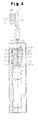
- the output shaft 30 may easily be arranged along the center axis C (refer to Fig. 4 ) of the electric toothbrush.
- the weight connection member 52 couples the magnetic block 20b and the weight 60. This increases the degree of design freedom for the shape of the weight 60. For example, when the weight 60 is box-shaped, the manufacturing of the weight 60 is facilitated.
- the electric toothbrush of the first embodiment includes the housing 70, the linear actuator 1, which is arranged in the housing 70, a control circuit 71, which controls the linear actuator 1, and a power supply such as a battery 72.
- the housing 70 includes a mount 73 corresponding to the fixing member 14.
- the fixing member 14, which is attached to the electromagnetic block 10 is fixed to the mount 73 in the housing 70, the linear actuator 1 is coupled to the housing 70.
- the winding 12 of the electromagnetic block 10 is connected to the control circuit 71 by a wire (not shown).
- the control circuit 71 may be, for example, included on a substrate arranged on the mount 73 in the housing 70. Power is supplied from the battery 72 to the control circuit 71.
- the housing 70 includes a through hole 74, and the output shaft 30 projects out of the housing 70 from the through hole 74.
- a brush attachment 75 for brushing teeth is connected to the distal end of the output shaft 30.
- the mount 73 which is fixed to the electromagnetic block 10, and a brush 76 of the brush attachment 75 are arranged on the same side of the center axis C of the electric toothbrush.
- the brush attachment 75 receives a pushing force F1 in accordance with contact between the teeth of the user and the brush 76.
- the electromagnetic block 10 fixed to the mount 73 generates a magnetic attraction force F2 at the permanent magnets 21 of the magnetic blocks 20a and 20b.
- the direction of the magnetic attraction force F2 between the electromagnetic block 10 and the magnetic blocks 20a and 20b is opposite to the direction in which the pushing force F1 acts on the brush attachment 75. Accordingly, the pushing force F1 and the attraction force F2 offset each other and reduce the load applied to the holding member 40 of the linear actuator 1.
- each plate spring of the plate spring units 43a and 43b of the holding member 40 are parallel to the direction in which the pushing force F1 acts on the brush attachment 75.
- the opposite ends of each plate spring unit support the electromagnetic block 10 and the magnetic blocks 20a and 20b.
- the pushing force F1 acting on the brush attachment 75 pulls the plate springs in a direction separating the magnetic blocks 20a and 20b from the fixed electromagnetic block 10.
- the pushing force F1 aids the plate spring units 43a and 43b to support the electromagnetic block 10 and the magnetic blocks 20a and 20b. Accordingly, the compression load on the plate spring units 43a and 43b may be reduced. This limits deformation of the holding member 40, in particular, the plate spring units 43a and 43b.
- the first embodiment has the advantages described below.
- a linear actuator 2 according to a second embodiment of the present invention will now be described focusing on differences from the first embodiment.
- the basic structure of the second embodiment is similar to that of the first embodiment. Same reference characters are given to those components that are substantially the same as the corresponding components of the first embodiment. Such components will not be described.
- the linear actuator 2 of the second embodiment differs from the first embodiment in the location of a weight 60.
- the magnetic block 20a and the magnetic block 20b of the second embodiment are arranged in parallel in a direction orthogonal to the reciprocation direction of the magnetic blocks 20a and 20b.
- the magnetic block 20a and the magnetic block 20b reciprocate in opposite phases.
- the output shaft connection member 50 couples the output shaft 30 to the magnetic block 20a.
- the output shaft connection member 50 couples the output shaft 30 to the magnetic block 20a.
- a weight connection member 55 couples the weight 61 to the magnetic block 20b.
- the weight 61 and the output shaft 30 are arranged at the same side in the reciprocation direction of the magnetic blocks 20a and 20b. In the illustrated example, the weight 61 is located between the output shaft 30 and the magnetic blocks 20a and 20b in the reciprocation direction of the magnetic blocks 20a and 20b.
- the output shaft 30 and the weight 61 are reciprocated in opposite phases. This offsets the vibration generated by the reciprocation of the magnetic blocks 20a and 20b and reduces vibration.
- the output shaft 30 and the weight 61 are arranged on the same side in the reciprocation direction of the magnetic blocks 20a and 20b. This allows for alignment of the center of gravity positions of the magnetic blocks 20a and 20b in the reciprocation direction of the magnetic blocks 20a and 20b.
- the weight 61 may be an annular member arranged parallel to the coupling portion 44 in the axial direction of the output shaft 30.
- the output shaft 30 is arranged to extend through central openings of the annular coupling portion 44 and the weight 61. This structure limits enlargement of the linear actuator 2.
- the linear actuator 2 of the second embodiment may also be fixed to the housing 70 of an electric toothbrush in the same manner as the first embodiment.
- the second embodiment has the following advantage
- a linear actuator 3 according to a third embodiment of the present invention will now be described focusing on differences from the first embodiment.
- the basic structure of the third embodiment is similar to that of the first embodiment. Same reference characters are given to those components that are substantially the same as the corresponding components of the first embodiment. Such components will not be described.
- the linear actuator 3 of the third embodiment differs from the first embodiment in the location of a weight 62.
- the magnetic block 20a and the magnetic block 20b of the third embodiment are arranged in parallel in a direction orthogonal to the reciprocation direction of the magnetic blocks 20a and 20b.
- the magnetic block 20a and the magnetic block 20b reciprocate in opposite phases.
- the output shaft connection member 50 couples the output shaft 30 to the magnetic block 20a.
- the output shaft connection member 50 couples the output shaft 30 to the magnetic block 20a.
- the weight 62 is coupled to the magnetic block 20b so that the weight 62 partially or entirely faces a side portion of the linear actuator 3 in a direction orthogonal to the reciprocation direction of the magnetic blocks 20a and 20b.
- the weight 62 is a single bent plate.
- the weight 62 includes two pieces extending parallel to the reciprocation direction of the magnetic blocks 20a and 20b. The two pieces respectively face two adjacent side surfaces of the linear actuator 3.
- the weight 62 is located at the opposite side of the output shaft 30 in the reciprocation direction of the magnetic blocks 20a and 20b.
- One of the two pieces of the weight 62 functions as a coupling portion coupled to the magnetic block 20b. This eliminates the need for a dedicated weight connection member that couples the weight 62 and the magnetic block 20b. Thus, the number of components may be decreased, and the manufacturing cost may be consequently reduced.
- the output shaft 30 and the weight 62 are reciprocated in opposite phases. This offsets the vibration generated by the reciprocation of the magnetic blocks 20a and 20b and reduces vibration.
- the weight 61 is arranged on the side opposite to the output shaft 30 in the reciprocation direction of the magnetic blocks 20a and 20b. Further, at least a portion of the weight 62 is arranged beside the linear actuator 3 parallel to the reciprocation direction of the magnetic blocks 20a and 20b. This allows for alignment of the center of gravity positions of the magnetic blocks 20a and 20b in the reciprocation direction of the magnetic blocks 20a and 20b and a direction orthogonal to the reciprocation direction.
- the linear actuator 3 may be shortened
- the third embodiment has the following advantage.
- a linear actuator 4 according to a fourth embodiment of the present invention will now be described focusing on differences from the first embodiment.
- the basic structure of the fourth embodiment is similar to that of the first embodiment. Same reference characters are given to those components that are substantially the same as the corresponding components of the first embodiment. Such components will not be described.
- the output shaft 30, the back yoke 22 of the magnetic block 20a, and an L-shaped connection portion 31 connecting the output shaft 30 and the back yoke 22 are formed integrally.
- a bolt 51 fixes the connection portion 31 to the holding member 40.
- connection portion 31 is L-shaped.
- the degree of design freedom is increased for the location of the output shaft 30 in a plane orthogonal to the reciprocation direction of the magnetic blocks 20a and 20b. This facilitates the arrangement of the output shaft 30 in the central portion of the linear actuator 4.
- the linear actuator 4 of the fourth embodiment may also be fixed to the housing 70 of an electric toothbrush in the same manner as the first embodiment.
- the fourth embodiment has the following advantage.
- a linear actuator 5 according to a fifth embodiment of the present invention will now be described with reference to Figs. 10 to 12 focusing on differences from the first embodiment.
- the basic structure of the fifth embodiment is similar to that of the first embodiment. Same reference characters are given to those components that are substantially the same as the corresponding components of the first embodiment. Such components will not be described.
- a through hole 45 extends through the plate spring unit 43a of the holding member 40.
- the output shaft 30 is inserted through the through hole 45 and coupled to the magnetic block 20a
- a connection portion 32 extends from the output shaft 30.
- An end of the connection portion 32 is coupled to an end of the back yoke 22 of the magnetic block 20a.
- the connection portion 32 extends through the through hole 45. This couples the output shaft 30 and the magnetic block 20a. Accordingly, the linear actuator 5 may be reduced in size in the direction orthogonal to both of the reciprocation direction of the magnetic blocks 20a and 20b and the direction in which the magnetic blocks 20a and 20b are arranged in parallel. Further, there is no need for a dedicated output shaft connection member that couples the magnetic block 20a and the output shaft 30. Thus, the number of components may be decreased, and the manufacturing cost may be consequently reduced.
- connection portion 32 includes a diagonal portion 32a that projects diagonally relative to the axial direction of the output shaft 30. Accordingly, adjustment of the length and inclination angle of the diagonal portion 32a increases the degree of design freedom for the location of the output shaft 30 in a plane orthogonal to the reciprocation direction of the magnetic blocks 20a and 20b. This facilitates the arrangement of the output shaft 30 in the central portion of the linear actuator 5.
- the output shaft 30, the back yoke 22 of the magnetic block 20a, and the connection portion 32 connecting the output shaft 30 and the back yoke 22 may be formed integrally.
- the linear actuator 5 of the fifth embodiment may also be fixed to the housing 70 of an electric toothbrush in the same manner as the first embodiment.
- the fifth embodiment has the following advantage.
- the shapes of the weights 60, 61, and 62 illustrated in the embodiments are only examples. The shapes may be changed so as not to interfere with the reciprocation of the magnetic blocks 20a and 20b and the output shaft 30.
- the coupling portion 44 is formed on the end that is closer to the output shaft 30.
- the coupling portion 44 may be formed on the end opposite to the output shaft 30.
- the coupling portion 44 may also be arranged on the ends of the magnetic blocks 20a and 20b on the output shaft side and the side opposite to the output shaft.
- the coupling portion 44 does not have to be formed integrally with the holding member 40.
- the coupling portion 44 which is discrete from the holding member 40, may be connected to the holding member 40.
- the holding member 40 and the coupling portion 44 do not have to be resin components and may be metal components.
- the holding member 40 only needs to be formed from a material that does not stretch much, and the coupling portion 44 only needs to be formed from an elastic material.
- the number of magnetic blocks 20 serving as movable elements is not limited to two and may be three or more.
- the movable elements are arranged in parallel and adjacent movable elements are reciprocated in opposite phases.
- An output shaft is connected to or formed on at least one of the movable elements so that the longitudinal axis conforms to the reciprocation direction of the movable element.
- the output shaft is connected to or formed on two or more movable elements.
- a weight is arranged on two or more movable elements.
- the weight is arranged on two or more movable elements. The weight may be omitted depending on the amount of vibration.
- the electromagnetic block 10 functions as a stator, and the magnetic block 20 functions as the movable element.
- the magnetic block 20 functions as a stator, and the electromagnetic block 10 functions as a movable element that reciprocates.
- one of the electromagnetic block 10 and the magnetic block 20 may be a plurality of blocks that are arranged in parallel.
- the linear actuator may be used as the drive source of an oral cavity hygiene device other than an electric toothbrush such as a stain removing device, an interdental brush, a tongue cleaner device, and the like or as the drive source of a device other than an oral cavity hygiene device
- a driven body for oral cavity hygiene may be connectable to the output shaft of the linear actuator such as a brush attachment for brushing teeth, a stain removal attachment, an interdental cleaning brush attachment, and a tongue cleaning brush attachment.
- a driven body such as the brush attachment 75 for brushing teeth may be removable from the output shaft 30.
Landscapes
- Health & Medical Sciences (AREA)
- Dentistry (AREA)
- Epidemiology (AREA)
- Life Sciences & Earth Sciences (AREA)
- Animal Behavior & Ethology (AREA)
- General Health & Medical Sciences (AREA)
- Public Health (AREA)
- Veterinary Medicine (AREA)
- Engineering & Computer Science (AREA)
- Power Engineering (AREA)
- Reciprocating, Oscillating Or Vibrating Motors (AREA)
- Brushes (AREA)
Applications Claiming Priority (2)
| Application Number | Priority Date | Filing Date | Title |
|---|---|---|---|
| JP2011265624A JP5945814B2 (ja) | 2011-12-05 | 2011-12-05 | リニアアクチュエータおよびこれを備える口腔衛生装置 |
| PCT/JP2012/007541 WO2013084438A1 (ja) | 2011-12-05 | 2012-11-22 | リニアアクチュエータおよび口腔衛生装置 |
Publications (3)
| Publication Number | Publication Date |
|---|---|
| EP2790309A1 true EP2790309A1 (de) | 2014-10-15 |
| EP2790309A4 EP2790309A4 (de) | 2015-12-30 |
| EP2790309B1 EP2790309B1 (de) | 2022-02-23 |
Family
ID=48573830
Family Applications (1)
| Application Number | Title | Priority Date | Filing Date |
|---|---|---|---|
| EP12854814.6A Active EP2790309B1 (de) | 2011-12-05 | 2012-11-22 | Linearantrieb und mundhygienevorrichtung |
Country Status (5)
| Country | Link |
|---|---|
| EP (1) | EP2790309B1 (de) |
| JP (1) | JP5945814B2 (de) |
| CN (1) | CN103959619B (de) |
| TW (1) | TW201330463A (de) |
| WO (1) | WO2013084438A1 (de) |
Cited By (6)
| Publication number | Priority date | Publication date | Assignee | Title |
|---|---|---|---|---|
| CN108880168A (zh) * | 2017-04-19 | 2018-11-23 | 松下知识产权经营株式会社 | 振动型线性致动器以及切断装置 |
| US10813733B2 (en) | 2016-09-12 | 2020-10-27 | Koninklijke Philips N.V. | Drivetrain assembly for a personal care device |
| EP3734808A1 (de) * | 2019-05-02 | 2020-11-04 | Braun GmbH | Körperhygienevorrichtung |
| US11646650B2 (en) | 2017-12-27 | 2023-05-09 | Guangzhou Chili Technology Co., Ltd. | Swing motor with two movable members having elastic support members and torsion elastic members |
| US11712326B2 (en) | 2019-05-02 | 2023-08-01 | Braun Gmbh | Personal care device |
| US11859687B2 (en) | 2019-05-02 | 2024-01-02 | Braun Gmbh | Motor with spring-mounted movable motor part and personal care device comprising such a motor |
Families Citing this family (5)
| Publication number | Priority date | Publication date | Assignee | Title |
|---|---|---|---|---|
| ES2693620T3 (es) * | 2012-07-13 | 2018-12-13 | Braun Gmbh | Motor lineal y dispositivo eléctrico con motor lineal |
| US10463460B2 (en) | 2015-01-28 | 2019-11-05 | Shanghai Shift Electrics Co., Ltd. | Personal cleaning care appliance |
| JP6659951B2 (ja) * | 2016-03-31 | 2020-03-04 | ミツミ電機株式会社 | アクチュエータ及び電動理美容器具 |
| CN106901857B (zh) * | 2017-05-02 | 2019-02-05 | 希尔顿(江苏)健康科技有限公司 | 一种拉拽式电动牙刷的驱动机构 |
| DK3628271T3 (da) * | 2018-09-27 | 2021-09-06 | Sirona Dental Systems Gmbh | Apparat til ændring af et fokuspunkt for et optisk system i en dental 3d-scanner og dental 3d-scanner |
Citations (2)
| Publication number | Priority date | Publication date | Assignee | Title |
|---|---|---|---|---|
| JPH09252843A (ja) * | 1996-03-26 | 1997-09-30 | Matsushita Electric Works Ltd | 電動歯ブラシ |
| EP2112754A2 (de) * | 2008-04-24 | 2009-10-28 | Panasonic Electric Works Co., Ltd. | Vibrierender Linearaktuator |
Family Cites Families (6)
| Publication number | Priority date | Publication date | Assignee | Title |
|---|---|---|---|---|
| JP2001112228A (ja) * | 1999-10-08 | 2001-04-20 | Matsushita Electric Ind Co Ltd | 磁石可動型リニアアクチュエータ |
| JP2002176758A (ja) | 2000-09-29 | 2002-06-21 | Matsushita Electric Works Ltd | リニアオシレータ及び電動歯ブラシ |
| JP3475949B2 (ja) | 2000-09-29 | 2003-12-10 | 松下電工株式会社 | リニアオシレータ |
| JP2005185067A (ja) * | 2003-12-22 | 2005-07-07 | Matsushita Electric Works Ltd | 振動型リニアアクチュエータ及びこれを備えたヘアカッター |
| JP4432840B2 (ja) * | 2005-06-21 | 2010-03-17 | パナソニック電工株式会社 | 振動型アクチュエータ |
| JP4591561B2 (ja) * | 2008-06-25 | 2010-12-01 | ミツミ電機株式会社 | アクチュエータ及びこれを用いた電動歯ブラシ |
-
2011
- 2011-12-05 JP JP2011265624A patent/JP5945814B2/ja active Active
-
2012
- 2012-11-22 CN CN201280058530.0A patent/CN103959619B/zh active Active
- 2012-11-22 WO PCT/JP2012/007541 patent/WO2013084438A1/ja active Application Filing
- 2012-11-22 EP EP12854814.6A patent/EP2790309B1/de active Active
- 2012-11-26 TW TW101144143A patent/TW201330463A/zh unknown
Patent Citations (2)
| Publication number | Priority date | Publication date | Assignee | Title |
|---|---|---|---|---|
| JPH09252843A (ja) * | 1996-03-26 | 1997-09-30 | Matsushita Electric Works Ltd | 電動歯ブラシ |
| EP2112754A2 (de) * | 2008-04-24 | 2009-10-28 | Panasonic Electric Works Co., Ltd. | Vibrierender Linearaktuator |
Non-Patent Citations (2)
| Title |
|---|
| None * |
| See also references of WO2013084438A1 * |
Cited By (10)
| Publication number | Priority date | Publication date | Assignee | Title |
|---|---|---|---|---|
| US10813733B2 (en) | 2016-09-12 | 2020-10-27 | Koninklijke Philips N.V. | Drivetrain assembly for a personal care device |
| CN108880168A (zh) * | 2017-04-19 | 2018-11-23 | 松下知识产权经营株式会社 | 振动型线性致动器以及切断装置 |
| US11235481B2 (en) | 2017-04-19 | 2022-02-01 | Panasonic Intellectual Property Management Co., Ltd. | Oscillatory linear actuator and cutting device |
| CN108880168B (zh) * | 2017-04-19 | 2022-09-23 | 松下知识产权经营株式会社 | 振动型线性致动器以及切断装置 |
| US11646650B2 (en) | 2017-12-27 | 2023-05-09 | Guangzhou Chili Technology Co., Ltd. | Swing motor with two movable members having elastic support members and torsion elastic members |
| EP3734808A1 (de) * | 2019-05-02 | 2020-11-04 | Braun GmbH | Körperhygienevorrichtung |
| WO2020222183A1 (en) * | 2019-05-02 | 2020-11-05 | Braun Gmbh | Personal hygiene device |
| US11712326B2 (en) | 2019-05-02 | 2023-08-01 | Braun Gmbh | Personal care device |
| US11793619B2 (en) | 2019-05-02 | 2023-10-24 | Braun Gmbh | Personal hygiene device |
| US11859687B2 (en) | 2019-05-02 | 2024-01-02 | Braun Gmbh | Motor with spring-mounted movable motor part and personal care device comprising such a motor |
Also Published As
| Publication number | Publication date |
|---|---|
| CN103959619A (zh) | 2014-07-30 |
| EP2790309B1 (de) | 2022-02-23 |
| CN103959619B (zh) | 2016-12-28 |
| WO2013084438A1 (ja) | 2013-06-13 |
| JP2013118779A (ja) | 2013-06-13 |
| EP2790309A4 (de) | 2015-12-30 |
| TW201330463A (zh) | 2013-07-16 |
| JP5945814B2 (ja) | 2016-07-05 |
Similar Documents
| Publication | Publication Date | Title |
|---|---|---|
| EP2790309B1 (de) | Linearantrieb und mundhygienevorrichtung | |
| EP1684402B1 (de) | Vibrierender Linearaktuator und elektrische Zahnbürste mit diesem Aktuator | |
| JP6365190B2 (ja) | リニアアクチュエータ及び電動ブラシ、電動切削機及び電動エアポンプ | |
| JP3800094B2 (ja) | 電動歯ブラシ | |
| DK2873144T3 (en) | ORAL HYGIENE INSTALLATION WITH A RESONANCE LINE ENGINE | |
| JP2004343931A (ja) | 振動型リニアアクチュエータ及びそれを用いた電動歯ブラシ | |
| JP4535172B2 (ja) | アクチュエータ及びこれを用いた電動歯ブラシ | |
| EP1684401A1 (de) | Linearaktuator für rollende und vibrierende Bewegung und elektrische Zahnbürste mit diesem Aktuator | |
| JP5984107B2 (ja) | リニアアクチュエータ構造体およびこれを備える口腔衛生装置 | |
| KR20100002059A (ko) | 액추에이터 및 이것을 사용한 전동칫솔 | |
| JP5929241B2 (ja) | アクチュエーター及び電動理美容器具 | |
| JP2005185067A (ja) | 振動型リニアアクチュエータ及びこれを備えたヘアカッター | |
| JP4487650B2 (ja) | 振動型リニアアクチュエータ及びこれを用いた往復式電気かみそり | |
| EP1091477B1 (de) | Schwingungsgenerator | |
| WO2017170188A1 (ja) | アクチュエータ及び電動理美容器具 | |
| AU2016303732B2 (en) | Actuator and electric beauty device | |
| JP2022077291A (ja) | リニア振動モータ | |
| JP2013123305A (ja) | リニアアクチュエータ及び口腔衛生装置 | |
| EP2727220B1 (de) | LINEARER VIBRATIONSMOTOR IM HANDGRIFF FÜR EIN KLEINES, HANDGEHALTENES ELEKTRISCHES GERÄT
 VORRICHTUNG | |
| JP2004023908A (ja) | 振動型リニアアクチュエータ | |
| JP3736282B2 (ja) | 振動型リニアアクチュエータ | |
| CN113437851A (zh) | 一种轴向直线往复振荡微电机及电动牙刷 | |
| KR101027215B1 (ko) | 진동형 리니어 액추에이터 |
Legal Events
| Date | Code | Title | Description |
|---|---|---|---|
| PUAI | Public reference made under article 153(3) epc to a published international application that has entered the european phase |
Free format text: ORIGINAL CODE: 0009012 |
|
| 17P | Request for examination filed |
Effective date: 20140520 |
|
| AK | Designated contracting states |
Kind code of ref document: A1 Designated state(s): AL AT BE BG CH CY CZ DE DK EE ES FI FR GB GR HR HU IE IS IT LI LT LU LV MC MK MT NL NO PL PT RO RS SE SI SK SM TR |
|
| DAX | Request for extension of the european patent (deleted) | ||
| RA4 | Supplementary search report drawn up and despatched (corrected) |
Effective date: 20151201 |
|
| RIC1 | Information provided on ipc code assigned before grant |
Ipc: H02K 33/16 20060101AFI20151125BHEP Ipc: A46B 15/00 20060101ALN20151125BHEP Ipc: A61C 17/22 20060101ALI20151125BHEP Ipc: A61C 17/34 20060101ALI20151125BHEP Ipc: A61C 17/20 20060101ALI20151125BHEP |
|
| STAA | Information on the status of an ep patent application or granted ep patent |
Free format text: STATUS: EXAMINATION IS IN PROGRESS |
|
| 17Q | First examination report despatched |
Effective date: 20170411 |
|
| STAA | Information on the status of an ep patent application or granted ep patent |
Free format text: STATUS: EXAMINATION IS IN PROGRESS |
|
| RIC1 | Information provided on ipc code assigned before grant |
Ipc: A46B 15/00 20060101ALN20210827BHEP Ipc: A61C 17/34 20060101ALI20210827BHEP Ipc: A61C 17/22 20060101ALI20210827BHEP Ipc: A61C 17/20 20060101ALI20210827BHEP Ipc: H02K 33/16 20060101AFI20210827BHEP |
|
| RIC1 | Information provided on ipc code assigned before grant |
Ipc: A46B 15/00 20060101ALN20210908BHEP Ipc: A61C 17/34 20060101ALI20210908BHEP Ipc: A61C 17/22 20060101ALI20210908BHEP Ipc: A61C 17/20 20060101ALI20210908BHEP Ipc: H02K 33/16 20060101AFI20210908BHEP |
|
| GRAP | Despatch of communication of intention to grant a patent |
Free format text: ORIGINAL CODE: EPIDOSNIGR1 |
|
| STAA | Information on the status of an ep patent application or granted ep patent |
Free format text: STATUS: GRANT OF PATENT IS INTENDED |
|
| RIC1 | Information provided on ipc code assigned before grant |
Ipc: A46B 15/00 20060101ALN20210929BHEP Ipc: A61C 17/34 20060101ALI20210929BHEP Ipc: A61C 17/22 20060101ALI20210929BHEP Ipc: A61C 17/20 20060101ALI20210929BHEP Ipc: H02K 33/16 20060101AFI20210929BHEP |
|
| RIC1 | Information provided on ipc code assigned before grant |
Ipc: A46B 15/00 20060101ALN20211001BHEP Ipc: A61C 17/34 20060101ALI20211001BHEP Ipc: A61C 17/22 20060101ALI20211001BHEP Ipc: A61C 17/20 20060101ALI20211001BHEP Ipc: H02K 33/16 20060101AFI20211001BHEP |
|
| INTG | Intention to grant announced |
Effective date: 20211021 |
|
| GRAS | Grant fee paid |
Free format text: ORIGINAL CODE: EPIDOSNIGR3 |
|
| GRAA | (expected) grant |
Free format text: ORIGINAL CODE: 0009210 |
|
| STAA | Information on the status of an ep patent application or granted ep patent |
Free format text: STATUS: THE PATENT HAS BEEN GRANTED |
|
| AK | Designated contracting states |
Kind code of ref document: B1 Designated state(s): AL AT BE BG CH CY CZ DE DK EE ES FI FR GB GR HR HU IE IS IT LI LT LU LV MC MK MT NL NO PL PT RO RS SE SI SK SM TR |
|
| REG | Reference to a national code |
Ref country code: GB Ref legal event code: FG4D |
|
| REG | Reference to a national code |
Ref country code: CH Ref legal event code: EP |
|
| REG | Reference to a national code |
Ref country code: DE Ref legal event code: R096 Ref document number: 602012077738 Country of ref document: DE |
|
| REG | Reference to a national code |
Ref country code: AT Ref legal event code: REF Ref document number: 1471207 Country of ref document: AT Kind code of ref document: T Effective date: 20220315 |
|
| REG | Reference to a national code |
Ref country code: IE Ref legal event code: FG4D |
|
| RAP4 | Party data changed (patent owner data changed or rights of a patent transferred) |
Owner name: PANASONIC HOLDINGS CORPORATION |
|
| REG | Reference to a national code |
Ref country code: LT Ref legal event code: MG9D |
|
| REG | Reference to a national code |
Ref country code: NL Ref legal event code: MP Effective date: 20220223 |
|
| REG | Reference to a national code |
Ref country code: AT Ref legal event code: MK05 Ref document number: 1471207 Country of ref document: AT Kind code of ref document: T Effective date: 20220223 |
|
| PG25 | Lapsed in a contracting state [announced via postgrant information from national office to epo] |
Ref country code: SE Free format text: LAPSE BECAUSE OF FAILURE TO SUBMIT A TRANSLATION OF THE DESCRIPTION OR TO PAY THE FEE WITHIN THE PRESCRIBED TIME-LIMIT Effective date: 20220223 Ref country code: RS Free format text: LAPSE BECAUSE OF FAILURE TO SUBMIT A TRANSLATION OF THE DESCRIPTION OR TO PAY THE FEE WITHIN THE PRESCRIBED TIME-LIMIT Effective date: 20220223 Ref country code: PT Free format text: LAPSE BECAUSE OF FAILURE TO SUBMIT A TRANSLATION OF THE DESCRIPTION OR TO PAY THE FEE WITHIN THE PRESCRIBED TIME-LIMIT Effective date: 20220623 Ref country code: NO Free format text: LAPSE BECAUSE OF FAILURE TO SUBMIT A TRANSLATION OF THE DESCRIPTION OR TO PAY THE FEE WITHIN THE PRESCRIBED TIME-LIMIT Effective date: 20220523 Ref country code: NL Free format text: LAPSE BECAUSE OF FAILURE TO SUBMIT A TRANSLATION OF THE DESCRIPTION OR TO PAY THE FEE WITHIN THE PRESCRIBED TIME-LIMIT Effective date: 20220223 Ref country code: LT Free format text: LAPSE BECAUSE OF FAILURE TO SUBMIT A TRANSLATION OF THE DESCRIPTION OR TO PAY THE FEE WITHIN THE PRESCRIBED TIME-LIMIT Effective date: 20220223 Ref country code: HR Free format text: LAPSE BECAUSE OF FAILURE TO SUBMIT A TRANSLATION OF THE DESCRIPTION OR TO PAY THE FEE WITHIN THE PRESCRIBED TIME-LIMIT Effective date: 20220223 Ref country code: ES Free format text: LAPSE BECAUSE OF FAILURE TO SUBMIT A TRANSLATION OF THE DESCRIPTION OR TO PAY THE FEE WITHIN THE PRESCRIBED TIME-LIMIT Effective date: 20220223 Ref country code: BG Free format text: LAPSE BECAUSE OF FAILURE TO SUBMIT A TRANSLATION OF THE DESCRIPTION OR TO PAY THE FEE WITHIN THE PRESCRIBED TIME-LIMIT Effective date: 20220523 |
|
| PG25 | Lapsed in a contracting state [announced via postgrant information from national office to epo] |
Ref country code: PL Free format text: LAPSE BECAUSE OF FAILURE TO SUBMIT A TRANSLATION OF THE DESCRIPTION OR TO PAY THE FEE WITHIN THE PRESCRIBED TIME-LIMIT Effective date: 20220223 Ref country code: LV Free format text: LAPSE BECAUSE OF FAILURE TO SUBMIT A TRANSLATION OF THE DESCRIPTION OR TO PAY THE FEE WITHIN THE PRESCRIBED TIME-LIMIT Effective date: 20220223 Ref country code: GR Free format text: LAPSE BECAUSE OF FAILURE TO SUBMIT A TRANSLATION OF THE DESCRIPTION OR TO PAY THE FEE WITHIN THE PRESCRIBED TIME-LIMIT Effective date: 20220524 Ref country code: FI Free format text: LAPSE BECAUSE OF FAILURE TO SUBMIT A TRANSLATION OF THE DESCRIPTION OR TO PAY THE FEE WITHIN THE PRESCRIBED TIME-LIMIT Effective date: 20220223 Ref country code: AT Free format text: LAPSE BECAUSE OF FAILURE TO SUBMIT A TRANSLATION OF THE DESCRIPTION OR TO PAY THE FEE WITHIN THE PRESCRIBED TIME-LIMIT Effective date: 20220223 |
|
| PG25 | Lapsed in a contracting state [announced via postgrant information from national office to epo] |
Ref country code: IS Free format text: LAPSE BECAUSE OF FAILURE TO SUBMIT A TRANSLATION OF THE DESCRIPTION OR TO PAY THE FEE WITHIN THE PRESCRIBED TIME-LIMIT Effective date: 20220623 |
|
| PG25 | Lapsed in a contracting state [announced via postgrant information from national office to epo] |
Ref country code: SM Free format text: LAPSE BECAUSE OF FAILURE TO SUBMIT A TRANSLATION OF THE DESCRIPTION OR TO PAY THE FEE WITHIN THE PRESCRIBED TIME-LIMIT Effective date: 20220223 Ref country code: SK Free format text: LAPSE BECAUSE OF FAILURE TO SUBMIT A TRANSLATION OF THE DESCRIPTION OR TO PAY THE FEE WITHIN THE PRESCRIBED TIME-LIMIT Effective date: 20220223 Ref country code: RO Free format text: LAPSE BECAUSE OF FAILURE TO SUBMIT A TRANSLATION OF THE DESCRIPTION OR TO PAY THE FEE WITHIN THE PRESCRIBED TIME-LIMIT Effective date: 20220223 Ref country code: EE Free format text: LAPSE BECAUSE OF FAILURE TO SUBMIT A TRANSLATION OF THE DESCRIPTION OR TO PAY THE FEE WITHIN THE PRESCRIBED TIME-LIMIT Effective date: 20220223 Ref country code: DK Free format text: LAPSE BECAUSE OF FAILURE TO SUBMIT A TRANSLATION OF THE DESCRIPTION OR TO PAY THE FEE WITHIN THE PRESCRIBED TIME-LIMIT Effective date: 20220223 Ref country code: CZ Free format text: LAPSE BECAUSE OF FAILURE TO SUBMIT A TRANSLATION OF THE DESCRIPTION OR TO PAY THE FEE WITHIN THE PRESCRIBED TIME-LIMIT Effective date: 20220223 |
|
| REG | Reference to a national code |
Ref country code: DE Ref legal event code: R097 Ref document number: 602012077738 Country of ref document: DE |
|
| PG25 | Lapsed in a contracting state [announced via postgrant information from national office to epo] |
Ref country code: AL Free format text: LAPSE BECAUSE OF FAILURE TO SUBMIT A TRANSLATION OF THE DESCRIPTION OR TO PAY THE FEE WITHIN THE PRESCRIBED TIME-LIMIT Effective date: 20220223 |
|
| PLBE | No opposition filed within time limit |
Free format text: ORIGINAL CODE: 0009261 |
|
| STAA | Information on the status of an ep patent application or granted ep patent |
Free format text: STATUS: NO OPPOSITION FILED WITHIN TIME LIMIT |
|
| REG | Reference to a national code |
Ref country code: DE Ref legal event code: R081 Ref document number: 602012077738 Country of ref document: DE Owner name: PANASONIC HOLDINGS CORPORATION, KADOMA-SHI, JP Free format text: FORMER OWNER: PANASONIC CORPORATION, KADOMA-SHI, OSAKA, JP |
|
| 26N | No opposition filed |
Effective date: 20221124 |
|
| PG25 | Lapsed in a contracting state [announced via postgrant information from national office to epo] |
Ref country code: SI Free format text: LAPSE BECAUSE OF FAILURE TO SUBMIT A TRANSLATION OF THE DESCRIPTION OR TO PAY THE FEE WITHIN THE PRESCRIBED TIME-LIMIT Effective date: 20220223 |
|
| PG25 | Lapsed in a contracting state [announced via postgrant information from national office to epo] |
Ref country code: MC Free format text: LAPSE BECAUSE OF FAILURE TO SUBMIT A TRANSLATION OF THE DESCRIPTION OR TO PAY THE FEE WITHIN THE PRESCRIBED TIME-LIMIT Effective date: 20220223 |
|
| REG | Reference to a national code |
Ref country code: CH Ref legal event code: PL |
|
| GBPC | Gb: european patent ceased through non-payment of renewal fee |
Effective date: 20221122 |
|
| REG | Reference to a national code |
Ref country code: BE Ref legal event code: MM Effective date: 20221130 |
|
| PG25 | Lapsed in a contracting state [announced via postgrant information from national office to epo] |
Ref country code: LI Free format text: LAPSE BECAUSE OF NON-PAYMENT OF DUE FEES Effective date: 20221130 Ref country code: IT Free format text: LAPSE BECAUSE OF FAILURE TO SUBMIT A TRANSLATION OF THE DESCRIPTION OR TO PAY THE FEE WITHIN THE PRESCRIBED TIME-LIMIT Effective date: 20220223 Ref country code: CH Free format text: LAPSE BECAUSE OF NON-PAYMENT OF DUE FEES Effective date: 20221130 |
|
| PG25 | Lapsed in a contracting state [announced via postgrant information from national office to epo] |
Ref country code: LU Free format text: LAPSE BECAUSE OF NON-PAYMENT OF DUE FEES Effective date: 20221122 |
|
| PG25 | Lapsed in a contracting state [announced via postgrant information from national office to epo] |
Ref country code: IE Free format text: LAPSE BECAUSE OF NON-PAYMENT OF DUE FEES Effective date: 20221122 Ref country code: GB Free format text: LAPSE BECAUSE OF NON-PAYMENT OF DUE FEES Effective date: 20221122 |
|
| PG25 | Lapsed in a contracting state [announced via postgrant information from national office to epo] |
Ref country code: FR Free format text: LAPSE BECAUSE OF NON-PAYMENT OF DUE FEES Effective date: 20221130 Ref country code: BE Free format text: LAPSE BECAUSE OF NON-PAYMENT OF DUE FEES Effective date: 20221130 |
|
| PGFP | Annual fee paid to national office [announced via postgrant information from national office to epo] |
Ref country code: DE Payment date: 20231121 Year of fee payment: 12 |
|
| PG25 | Lapsed in a contracting state [announced via postgrant information from national office to epo] |
Ref country code: HU Free format text: LAPSE BECAUSE OF FAILURE TO SUBMIT A TRANSLATION OF THE DESCRIPTION OR TO PAY THE FEE WITHIN THE PRESCRIBED TIME-LIMIT; INVALID AB INITIO Effective date: 20121122 |
|
| PG25 | Lapsed in a contracting state [announced via postgrant information from national office to epo] |
Ref country code: CY Free format text: LAPSE BECAUSE OF FAILURE TO SUBMIT A TRANSLATION OF THE DESCRIPTION OR TO PAY THE FEE WITHIN THE PRESCRIBED TIME-LIMIT Effective date: 20220223 |
|
| PG25 | Lapsed in a contracting state [announced via postgrant information from national office to epo] |
Ref country code: MK Free format text: LAPSE BECAUSE OF FAILURE TO SUBMIT A TRANSLATION OF THE DESCRIPTION OR TO PAY THE FEE WITHIN THE PRESCRIBED TIME-LIMIT Effective date: 20220223 |