EP2790277B1 - Receptacle - Google Patents
Receptacle Download PDFInfo
- Publication number
- EP2790277B1 EP2790277B1 EP14159264.2A EP14159264A EP2790277B1 EP 2790277 B1 EP2790277 B1 EP 2790277B1 EP 14159264 A EP14159264 A EP 14159264A EP 2790277 B1 EP2790277 B1 EP 2790277B1
- Authority
- EP
- European Patent Office
- Prior art keywords
- plug
- portions
- contact
- contacts
- receptacle
- Prior art date
- Legal status (The legal status is an assumption and is not a legal conclusion. Google has not performed a legal analysis and makes no representation as to the accuracy of the status listed.)
- Not-in-force
Links
Images


Classifications
-
- H—ELECTRICITY
- H01—ELECTRIC ELEMENTS
- H01R—ELECTRICALLY-CONDUCTIVE CONNECTIONS; STRUCTURAL ASSOCIATIONS OF A PLURALITY OF MUTUALLY-INSULATED ELECTRICAL CONNECTING ELEMENTS; COUPLING DEVICES; CURRENT COLLECTORS
- H01R27/00—Coupling parts adapted for co-operation with two or more dissimilar counterparts
-
- H—ELECTRICITY
- H01—ELECTRIC ELEMENTS
- H01R—ELECTRICALLY-CONDUCTIVE CONNECTIONS; STRUCTURAL ASSOCIATIONS OF A PLURALITY OF MUTUALLY-INSULATED ELECTRICAL CONNECTING ELEMENTS; COUPLING DEVICES; CURRENT COLLECTORS
- H01R13/00—Details of coupling devices of the kinds covered by groups H01R12/70 or H01R24/00 - H01R33/00
- H01R13/62—Means for facilitating engagement or disengagement of coupling parts or for holding them in engagement
- H01R13/627—Snap or like fastening
- H01R13/6275—Latching arms not integral with the housing
-
- H—ELECTRICITY
- H01—ELECTRIC ELEMENTS
- H01R—ELECTRICALLY-CONDUCTIVE CONNECTIONS; STRUCTURAL ASSOCIATIONS OF A PLURALITY OF MUTUALLY-INSULATED ELECTRICAL CONNECTING ELEMENTS; COUPLING DEVICES; CURRENT COLLECTORS
- H01R24/00—Two-part coupling devices, or either of their cooperating parts, characterised by their overall structure
- H01R24/60—Contacts spaced along planar side wall transverse to longitudinal axis of engagement
- H01R24/62—Sliding engagements with one side only, e.g. modular jack coupling devices
Definitions
- This invention relates to a receptacle mateable with at least two different types of plugs and further points to a special plug mateable with this receptacle.
- Patent Document 1 JP-A 2008-301492
- Patent Document 2 CN 202 772 376 U & US2014/065889 A1
- the receptacle of Patent Document 1 has a plurality of first contacts insert-molded in a holding member and a plurality of second contacts press-fit in the holding member.
- the first contacts are compliant with a universal serial bus (USB) standard.
- the first contact does not have a spring property, while the second contact has a spring property.
- each of the first contacts has an unmovable contact portion, while each of the second contacts has a contact portion that is movable up and down because of the resiliency of the second contact.
- the contact portions of the first contacts are arranged in a lateral direction.
- the contact portions of the second contacts are located under and behind the contact portions of the first contacts to be arranged in the lateral direction.
- the receptacle of Patent Document 1 has a limit on reducing its size in an up-down direction because of its positional relation between the contact portions of the first contacts and the contact portions of the second contacts.
- Patent Document 2 shows a connector, consisting of a Plug connector and receptable connector, including a first group of contacts and a second group of contacts.
- the invention according to Patent Document 2 is compatible with Micro US and USB 3.0 standards.
- the objective technical problem is solved by a receptacle according to claim 1and a system according to claim 3. All further preferable advancements are subject of the dependent claims.
- a first aspect of the present invention provides a receptacle according to claim 1 selectively
- a side aspect which is not subject of the present invention is a plug mateable, as the second plug, with the receptacle of the first aspect.
- the plug has a plug mating end that is received in the receptacle under a mated state where the plug is mated with the receptacle.
- the plug comprises a plug holding-member, a plurality of first plug-contacts and a plurality of second plug-contacts.
- the plug holding-member holds the first plug-contacts and the second plug-contacts.
- Each of the first plug-contacts has a first plug-contact-portion. The first plug-contact-portions are brought into contact with the first contact portions of the first contacts, respectively, under the mated state.
- Each of the second plug-contacts has a second plug-contact-portion.
- the second plug-contact-portions are brought into contact with the second contact portions of the second contacts, respectively, under the mated state.
- a distance between the first plug-contact-portion and the plug mating end is longer than another distance between the second plug-contact-portion and the plug mating end.
- the second plug-contacts are grouped into two groups. In the lateral direction, the first plug-contact-portions are located between the second plug-contact-portions of the second plug-contacts of one of the two groups and the second plug-contact-portions of the second plug-contacts of a remaining one of the two groups.
- the first contact portions of the first contacts are located forward of the second contact portions of the second contacts. Moreover, the first contact portions are located between the two groups of the second contact portions in the lateral direction.
- a section for the first contacts and another section for the second contacts of the present invention do not overlap each other in the up-down direction. According to the present invention, the size of the receptacle in the up-down direction can be reduced.
- the receptacle of Patent Document 1 has the limit on reducing its size in the front-rear direction because of necessity of providing the spring property for the contact that is located rearward, or the second contact. In contrast, for example, when the extending portion of the second contact is not provided with the spring property, a size of the receptacle in the front-rear direction can be reduced.
- a receptacle 500 is a connector selectively mateable with a first plug 100 and a second plug 300 along the Y-direction (front-rear direction).
- the receptacle 500 according to the present embodiment is mateable with the first plug 100, as shown in Fig. 2 , and is mateable with the second plug 300, as shown in Fig. 3 .
- a direction will be described based on the receptacle 500.
- the negative Y-side is the front side while the positive Y-side is the rear side.
- the positive Z-side is the upper side while the negative Z-side is the lower side.
- a first plug 100 which is connectable with the receptacle 500 is a connector compliant with a universal serial bus (USB) 2.0 standard.
- the first plug 100 has an end 110 and a first lock portion 120.
- the first lock portion 120 protrudes in the positive Z-direction and is movable along the Z-direction.
- the first lock portion 120 is also compliant with the USB 2.0 standard. Explanation about contacts and so on of the first plug 100 will be made below in conjunction with explanation about the second plug 300.
- a second plug 300 which is connectable with the receptacle 500 is a connector different from the first plug 100. More specifically, the second plug 300 has an interface formed by modifying an interface of the first plug 100 to include a plurality of contacts in addition to the contacts of the first plug 100. The interface of the second plug 300 includes an interface related to signal transmission of the first plug 100.
- the second plug 300 has a plug mating end 310.
- the plug mating end 310 is received in the receptacle 500 under a mated state where the second plug 300 is mated with the receptacle 500.
- the second plug 300 comprises a plurality of first plug-contacts 320 each made of a conductor, a plurality of second plug-contacts 340 each made of a conductor, a plug holding-member 360 made of an insulator, a lock member 370 made of a metal and a plug shell 390 made of a metal.
- the first plug-contacts 320 are held by the plug holding-member 360. Because the first plug-contacts 320 are compliant with the USB 2.0 standard, the number of the first plug-contacts 320 is five. As shown in Fig. 10 , each of the first plug-contacts 320 has a held portion 322, a spring portion 324 and a first plug-contact-portion 326. The held portions 322 are held by the plug holding-member 360. Each of the spring portions spring portions 324, respectively.
- the first plug 100 is also provided with contacts corresponding to the first plug-contacts 320.
- the second plug-contacts 340 are also held by the plug holding-member 360.
- each of the second plug-contacts 340 has a held portion (wide portion) 342, a spring portion 344 and a second plug-contact-portion 346.
- the held portions 342 are held by the plug holding-member 360.
- Each of the spring portions 344 is resiliently deformable.
- the second plug-contact-portions 346 are supported by the spring portions 344, respectively.
- the second plug-contacts 340 are divided into sets, each of which includes two of the second plug-contacts 340.
- the second plug-contacts 340 are grouped into two groups (sets).
- the second plug-contacts 340 of each group (set) form a pair of contacts for transmitting differential signals.
- a width of the held portion 342 is equal to or more than twice of another width of the second plug-contact-portion 346.
- the held portion 342 has a size equal to or more than twice of that of the second plug-contact-portion 346.
- This wide held portion 342 is provided in order to match its impedance with a mating contact, or a second contact 530, which is described later. Since the second plug-contacts 340 have the thus-configured held portions 342, respectively, the second plug-contacts 340 can be used for high speed signal transmission which satisfies a USB 3.0 specification.
- the first plug-contact-portions 326 are located away from the plug mating end 310, which is an end of the second plug 300, in the Y-direction (front-rear direction) in comparison with the second plug-contact-portions 346.
- the first plug-contact-portions 326 are nearer to the negative Y-side end of the second plug 300 than the second plug-contact-portions 346.
- a distance between the first plug-contact-portion 326 and the plug mating end 310 is longer than another distance between the second plug-contact-portion 346 and the plug mating end 310.
- the first plug-contact-portions 326 and the second plug-contact-portions 346 are arranged in the X-direction (lateral direction) so that the second plug-contact-portions 346 of the second plug-contacts 340 of one of the groups, the first plug-contact-portions 326 and the second plug-contact-portions 346 of the second plug-contacts 340 of a remaining one of the groups are arranged in this order.
- the first plug-contact-portions 326 are located between the two groups of the second plug-contact-portions 346 of the second plug-contacts 340.
- the plug holding-member 360 includes an insert-molding member 362, an outer member 364 and a cover member 366.
- the insert-molding member 362 holds the first plug-contacts 320 and the second plug-contacts 340. More specifically, the held portions 322 of the first plug-contacts 320 and the held portions 342 of the second plug-contacts 340 are embedded into the insert-molding member 362 via insert-molding when the insert-molding member 362 is molded so that the held portions 322 and the held portions 342 are held by the insert-molding member 362.
- the first plug-contact-portions 326 and the second plug-contact-portions 346 are arranged in the aforementioned arrangement by this holding.
- the outer member 364 is a member which is attached to the outside of the insert-molding member 362.
- the cover member 366 covers the negative Y-side end, or an end opposite to the plug mating end 310 in the Y-direction (front-rear direction), of each of the insert-molding member 362 and the outer member 364. consist of a single member, two members, four members or more members.
- the lock member 370 is formed by punching out a single metal sheet (base member) while not bending nor folding the base member. As shown in Fig. 6 , this lock member 370 has a U-like shape including a base portion 372 and two arms 374. The arms 374 are located at opposite ends of the base portion 372 in the X-direction (lateral direction), respectively, and extend from the base portion 372 toward the plug mating end 310 along the positive Y-direction.
- the arms 374 are resiliently deformable in the XY-plane.
- Each of the arms 374 is formed with a recess 376 recessed inward in the X-direction.
- the arm 374 has a meander shape. Because the recess 376 is provided, stress generated upon resilient deformation of the arm 374 can be prevented from being concentrated between the arm 374 and the base portion 372. Thus, the recess 376 has a function to relieve the stress generated upon the resilient deformation of the arm 374.
- the shape of the recess 376 of the arm 374 is not limited to the illustrated shape.
- the shape of the recess 376 may be a more rounded shape or a more angular shape, provided that the arm 374 meanders.
- Each of the arms 374 has a second lock portion (lock portion) 378.
- the second lock portion 378 is provided in the vicinity of an end, or the positive Y-side end, of the arm 374.
- the second lock portions 378 protrude outward in the X-direction.
- the second lock portions 378 are supported by the arms 374, respectively, to be movable in the X-direction by the resilient deformation of the arms 374.
- the lock member 370 is further provided with a press-fit portion 380 and two fixed portions 382.
- the press-fit portion 380 extends from the base portion 372 toward the plug mating end 310 along the positive Y-direction.
- the press-fit portion 380 is press-fit in and held by the outer member 364 of the plug at a middle portion of the base portion 372 in the X-direction.
- the lock member 370 has a line-symmetrical shape with respect to an imaginary line which extends along the Y-direction through the middle point of the press-fit portion 380 in the X-direction.
- This lock member 370 has a so-called tuning fork structure so that secure lock can be realized in comparison with a case where the two lock portions 378 are provided to separated members, respectively.
- the second plug-contact-portions 346 are located outward of the first plug-contact-portions 326 in the X-direction and located on the positive Y-side, or toward the plug mating end 310, in the Y-direction in comparison with the first plug-contact-portions 326. Accordingly, the second plug 300 is formed with a space that does not interfere with the first plug-contact-portions 326 and the second plug-contact-portions 346. This space is located on the negative Y-side, or a side further away from the plug mating end 310, in comparison with the second plug-contact-portions 346 and located outward of the first plug-contact-portions 326 in the X-direction.
- the lock member 370 is provided by using this space. Moreover, the lock member 370 is located toward the positive Z-side of the insert-molding member 362, or above the insert-molding member 362. Since the lock member 370 is located toward the positive Z-side of the insert-molding member 362, the lock member 370 is not brought into contact with the first plug-contact-portions 326 and the second plug-contact-portions 346.
- the second lock portions 378 are located on the negative Y-side, or a side further away from the plug mating end 310, in comparison with the second plug-contact-portions 346 and located outward of the first plug-contact-portions 326 in the X-direction. Accordingly, even when the arms 374 are resiliently deformed, the lock member 370 is not brought into contact with the first plug-contact-portions 326 and the second plug-contact-portions 346.
- the fixed portions 382 extend from the base portion 372 and away from the plug mating end 310, or extend along the negative Y-direction.
- the fixed portions 382 are press-fit in and fixed to the cover member 366 of the plug holding-member 360.
- the fixed portions 382 have a function to combine the cover member 366 with the insert-molding member 362 and the outer member 364.
- the fixed portions 382 have a function to prevent the lock member 370 from pivoting even in a case where the lock member 370 receives undesirable momentum in the XY-plane.
- the plug shell 390 consists of two members.
- the plug shell 390 is attached to the plug holding-member 360 to cover the plug holding-member 360 by combining the two members with each other.
- the second plug 300 having such structure is to be connected, for example, to a signal cable.
- the lock member 370 has the press-fit portion 380 press-fit in the outer member 364 and the fixed portions 382 press-fit in the cover member 366.
- the lock member 370 may have only the press-fit portion 380 or only the fixed portions 382, provided that the lock member 370 is securely held by the plug holding-member 360.
- the receptacle 500 comprises a plurality of first contacts 510 each made of a conductor, a plurality of second contacts 530 each made of a conductor, a holding member 550 made of an insulator and a shell 580 made of a metal.
- the holding member 550 has a rear portion 552, a plate-like portion 560 and an abutment portion 570.
- the plate-like portion 560 extends forward along the negative Y-direction from the rear portion 552.
- the plate-like portion 560 has a lower surface 560L in the Z-direction (up-down direction).
- the abutment portion 570 is provided to be located toward the negative Z-side of the plate-like portion 560, or under the plate-like portion 560, and located toward the negative Y-side of the rear portion 552, or in front of the rear portion 552.
- the plate-like portion 560 has a first portion 562 and two second portions 564.
- the abutment portion 570 is located under the first portion 562.
- the first portion 562 is a portion corresponding to the first contacts 510 while the second portions 564 are portions corresponding to the second contacts 530.
- the first portion 562 and the second portions 564 extend forward along the negative Y-direction from the rear portion 552.
- the first portion 562 has a size larger than that of the second portion 564.
- the first portion 562 is longer than the second portion 564.
- the first portion 562 extends forward along the negative Y-direction beyond the second portions 564.
- the first portion 562 is sandwiched between the second portions 564 in the X-direction (lateral direction).
- the plate-like portion 560 has a T-like shape in the XY-plane. As can be seen from Figs.
- the plate-like portion 560 according to the present embodiment has an almost uniform thickness or size in the Z-direction. However, the plate-like portion 560 may partially have a thick portion or a thin portion. Moreover, the plate-like portion 560 may have some steps.
- the negative Y-side end, or the front end, of the abutment portion 570 is located at a position same as a position of the negative Y-side end, or the front end, of the second portion 564.
- the end 110 of the first plug 100 is brought into abutment with the abutment portion 570 to be stopped. Accordingly, the second portions 564 are guarded.
- the second contacts 530 are provided at the second portions 564. Accordingly, the second contacts 530 are also guarded.
- the negative Y-side end, or the front end, of the abutment portion 570 may be located forward of the negative Y-side end, or the front end, of the second portion 564 in order to more securely guard the second portions 564 and the second contacts 530.
- the number of the first contacts 510 is five.
- the first contacts 510 are connected to the first plug-contacts 320, respectively, when the second plug 300 is mated with the receptacle 500.
- the first contacts 510 are connected to the respective contacts (not shown) corresponding to the first plug-contacts 320 when the first plug 100 is mated with the receptacle 500.
- the first contacts 510 correspond to the first plug-contacts 320.
- the first contacts 510 are compliant with the USB 2.0 standard.
- each of the first contacts 510 has a first held portion 512 and a first extending portion 514.
- the first held portions 512 are held by the rear portion 552 of the holding member 550.
- the first extending portions 514 extend forward along the negative Y-direction directly from the first held portions 512, respectively.
- Each of the first extending portions 514 has a part that functions as a first contact portion 516. In other words, the first extending portion 514 is provided with the first contact portion 516.
- the first contact portion 516 is a part which is located on the negative Y-side in comparison with the abutment portion 570, or located forward of the abutment portion 570.
- the first contact portions 516 are connectable with both the first plug 100 and the second plug 300.
- the first contact portions 516 are brought into contact with the first plug-contact-portions 326 of the first plug-contacts 320, respectively, under the mated state of the receptacle 500 with the second plug 300.
- the first contact portions 516 are brought into contact with the contact portions of the contacts corresponding to the first plug-contacts 320, respectively, under the mated state of the receptacle 500 with the first plug 100.
- the first portion 562 corresponds to the first extending portions 514.
- the first contact portions 516 are exposed on the lower surface 560L of the first portion 562 of the plate-like portion 560 to be contactable.
- the first contact portion 516 has a strip-like shape extending in the XY-plane, and the first extending portion 514 does not have a spring property.
- the first contact portions 516 according to the present embodiment are neither deformed nor moved when the first contacts 510 are connected to the first plug-contacts 320 or the contacts (not shown) corresponding to the first plug-contacts 320.
- the second contacts 530 are divided into two groups (sets) each of which includes two of the second contacts 530.
- the second contacts 530 are connected to the second plug-contacts 340, respectively, when the second plug 300 is mated with the receptacle 500.
- the second contacts 530 correspond to the second plug-contacts 340.
- the second contacts 530 according to the present embodiment are used for transmitting high speed signals which satisfy the USB 3.0 specification.
- the first plug 100 is not provided with any contact corresponding to the second contact 530.
- each of the second contacts 530 has a second held portion 532 and a second extending portion 534.
- the second held portions 532 are held by the rear portion 552 of the holding member 550.
- the second extending portions 534 extend forward along the negative Y-direction directly from the first held portions 512, respectively. Almost all the parts of the second extending portion 534 function as a second contact portion 536. In other words, the second extending portion 534 is provided with the second contact portion 536.
- the second contact portions 536 are connectable with only the second plug 300 between the first plug 100 and the second plug 300. In detail, the second contact portions 536 are brought into contact with the second plug-contact-portions 346 of the second plug-contacts 340, respectively, under the mated state of the receptacle 500 with the second plug 300.
- the second portions 564 corresponds to the second extending portions 534.
- the second contact portions 536 are exposed on the lower surfaces 560L of the second portions 564 of the plate-like portion 560 to be contactable.
- the second contact portion 536 has a strip-like shape extending in the XY-plane, and the second extending portion 534 does not have a spring property.
- the second contact portions 536 according to the present embodiment are neither deformed nor moved when the second contacts 530 are connected to the second plug-contacts 340 (for example, see Fig. 5 ).
- a size of the connector in the front-rear direction cannot be reduced beyond a certain limitation.
- the second contact 530 is not required to have a spring property, a size of the second extending portion 534 in the Y-direction (front-rear direction) can be reduced.
- a size of the receptacle 500 in the Y-direction (front-rear direction) can be reduced.
- the first contact portions 516 and the second contact portions 536 are located in the common XY-plane.
- the first contact portions 516 and the second contact portions 536 are located at the same level as one another in the Z-direction.
- the present invention is not limited thereto.
- the first contact portions 516 may be located some distance apart from the second contact portions 536 in the Z-direction.
- it is desirable that the first contact portions 516 and the second contact portions 536 are located in the common XY-plane like the present embodiment.
- the first contact portions 516 are located toward the negative Y-side of the second contact portions 536, or forward of the second contact portions 536.
- the second contact portions 536 are grouped into two groups (sets).
- the first contact portions 516 and the second contact portions 536 are arranged in the X-direction (lateral direction) so that the two second contact portions 536 of one of the groups (sets), the first contact portions 516 and the two second contact portions 536 of a remaining one of the groups (sets) are arranged in this order.
- the first contact portions 516 are located between the two groups (sets) of the second contact portions 536.
- the second contact portions 536 which form differential pairs for transmitting high speed signals which satisfy the USB 3.0 specification, are arranged to sandwich the first contact portions 516 which are compliant with the USB 2.0 standard.
- this arrangement allows one of ground contacts to be omitted. Similar effect can also be obtained by the previously described arrangement of the first plug-contact-portions 326 and the second plug-contact-portions 346.
- the first contacts 510 and the second contacts 530 are partially embedded into the holding member 550 via insert-molding when the holding member 550 is molded so that, as described above, the first held portions 512 and the second held portions 532 are held by the rear portion 552 of the holding member 550.
- the present invention is not limited thereto.
- the first contacts 510 and the second contacts 530 may be press-fit into and held by the holding member 550.
- the first extending portion 514 and the second extending portion 534 are the portions that extend forward directly from the first held portion 512 and the second held portion 532, respectively.
- the size of the receptacle 500 in the Z-direction (up-down direction) can be reduced.
- the shell 580 is formed to have a box-like shape including an upper portion 582 and two side portions 586.
- the shell 580 constitutes a receive portion for receiving a mating portion of the first plug 100 and the mating portion (plug mating end 310) of the second plug 300.
- the shell 580 covers, at least in part, the holding member 550.
- the shell 580 has two first locked portions 584 and two second locked portions 588. The first locked portions 584 are formed in the upper portion 582 of the shell 580 while the second locked portions 588 are formed in the side portions 586 of the shell 580, respectively.
- the first locked portions 584 can partially receive the first lock portions 120 of the first plug 100, respectively, while the second locked portions 588 can partially receive the second lock portions 378 of the second plug 300, respectively.
- the first locked portions 584 receive the first lock portions 120 to lock the mated state when the first plug 100 is mated with the receptacle 500.
- the second locked portions 588 receive the second lock portions 378 to lock the mated state when the second plug 300 is mated with the receptacle 500. Since the shell 580 according to the present invention is formed with the first locked portions 584 and the second locked portions 588, it is possible to lock the mated state in any case where any one of the first plug 100 and the second plug 300 is mated with the receptacle 500.
- any of the first contact 510 and the second contact 530 provided in the receptacle 500 does not have a spring property in the aforementioned embodiment, one of the first contact 510 and the second contact 530 may have a spring property.
- each of the first held portions 512 of the first contacts 510 and the second held portions 532 of the second contacts 530 is formed by bending to have a crank shape
- the present invention is not limited thereto.
- the rear side of each of the first held portions 512 and the second held portions 532 may extend straight rearward along the positive Y-direction.
- each of the illustrated first contacts 510 and the illustrated second contacts 530 is a so-called surface mount technology (SMT) contact
- each of the first contacts 510 and the second contacts 530 may be a through hole contact.
- the receptacle 500 may be a straight connector that has a mating surface in parallel to a circuit board (not shown) where the receptacle 500 is mounted. Moreover, the receptacle 500 may be a drop-in connector that is to be arranged in a recess formed in the circuit board.
- the first plug-contact 320 and the first contact 510 are compliant with the USB 2.0 standard. However, the present invention is not limited thereto. The first plug-contact 320 and the first contact 510 may be compliant with another standard or may be designed proprietarily.
- the second plug-contact 340 and the second contact 530 are contacts for transmitting high speed signals which satisfy the USB 3.0 specification.
- the present invention is not limited thereto. The present invention can be applied to various usages.
Landscapes
- Coupling Device And Connection With Printed Circuit (AREA)
- Details Of Connecting Devices For Male And Female Coupling (AREA)
Description
- This invention relates to a receptacle mateable with at least two different types of plugs and further points to a special plug mateable with this receptacle.
- For example, this type of receptacle is disclosed in
JP-A 2008-301492 CN 202 772 376 U &US2014/065889 A1 (Patent Document 2), the content. - As shown in
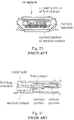
Figs. 20 and 21 , the receptacle of Patent Document 1 has a plurality of first contacts insert-molded in a holding member and a plurality of second contacts press-fit in the holding member. The first contacts are compliant with a universal serial bus (USB) standard. The first contact does not have a spring property, while the second contact has a spring property. In detail, each of the first contacts has an unmovable contact portion, while each of the second contacts has a contact portion that is movable up and down because of the resiliency of the second contact. The contact portions of the first contacts are arranged in a lateral direction. The contact portions of the second contacts are located under and behind the contact portions of the first contacts to be arranged in the lateral direction. - The receptacle of Patent Document 1 has a limit on reducing its size in an up-down direction because of its positional relation between the contact portions of the first contacts and the contact portions of the second contacts.
- Patent Document 2 shows a connector, consisting of a Plug connector and receptable connector, including a first group of contacts and a second group of contacts. The invention according to Patent Document 2 is compatible with Micro US and USB 3.0 standards.
- It is therefore an object of the present invention to provide a receptacle that is mateable with at least two different types of plugs and that can be further reduced in size, and a system of a receptacle, a first plug and a second plug. Moreover, the present invention points to a plug that has a structure preferable to reduce the size of this type of the receptacle. The objective technical problem is solved by a receptacle according to claim 1and a system according to claim 3. All further preferable advancements are subject of the dependent claims.
- A first aspect of the present invention provides a receptacle according to claim 1 selectively
- A side aspect which is not subject of the present invention is a plug mateable, as the second plug, with the receptacle of the first aspect. The plug has a plug mating end that is received in the receptacle under a mated state where the plug is mated with the receptacle. The plug comprises a plug holding-member, a plurality of first plug-contacts and a plurality of second plug-contacts. The plug holding-member holds the first plug-contacts and the second plug-contacts. Each of the first plug-contacts has a first plug-contact-portion. The first plug-contact-portions are brought into contact with the first contact portions of the first contacts, respectively, under the mated state. Each of the second plug-contacts has a second plug-contact-portion. The second plug-contact-portions are brought into contact with the second contact portions of the second contacts, respectively, under the mated state. In the front-rear direction, a distance between the first plug-contact-portion and the plug mating end is longer than another distance between the second plug-contact-portion and the plug mating end. The second plug-contacts are grouped into two groups. In the lateral direction, the first plug-contact-portions are located between the second plug-contact-portions of the second plug-contacts of one of the two groups and the second plug-contact-portions of the second plug-contacts of a remaining one of the two groups.
- As described above, the first contact portions of the first contacts are located forward of the second contact portions of the second contacts. Moreover, the first contact portions are located between the two groups of the second contact portions in the lateral direction. Thus, unlike the receptacle of Patent Document 1, a section for the first contacts and another section for the second contacts of the present invention do not overlap each other in the up-down direction. According to the present invention, the size of the receptacle in the up-down direction can be reduced.
- The receptacle of Patent Document 1 has the limit on reducing its size in the front-rear direction because of necessity of providing the spring property for the contact that is located rearward, or the second contact. In contrast, for example, when the extending portion of the second contact is not provided with the spring property, a size of the receptacle in the front-rear direction can be reduced.
- An appreciation of the objectives of the present invention and a more complete understanding of its structure may be had by studying the following description of the preferred embodiment and by referring to the accompanying drawings.
-
-
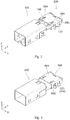
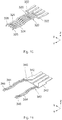
Fig. 1 is a perspective view showing a receptacle, a first plug and a second plug (plug) according to an embodiment of the present invention. -
Fig. 2 is a perspective view showing the receptacle and the first plug ofFig. 1 , wherein the receptacle and the first plug are in a mated state. -
Fig. 3 is a perspective view showing the receptacle and the second plug ofFig. 1 , wherein the receptacle and the second plug are in another mated state. -
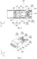
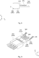
Fig. 4 is a side view showing the second plug ofFig. 1 . -
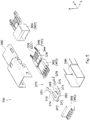
Fig. 5 is an exploded, perspective view showing the second plug ofFig. 4 . -
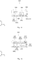
Fig. 6 is a cross-sectional view showing the second plug ofFig. 4 , taken along line VI-VI. -
Fig. 7 is a perspective view showing the second plug ofFig. 4 without its shell. -
Fig. 8 is a side view showing the second plug ofFig. 7 . -
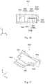
Fig. 9 is a perspective view showing an insert-molding member of the second plug ofFig. 5 , wherein the insert-molding member is embedded with first plug-contacts and second plug-contacts. -
Fig. 10 is a perspective view showing the first plug-contacts ofFig. 9 . -
Fig. 11 is a perspective view showing the second plug-contacts ofFig. 9 . -
Fig. 12 is a perspective view showing a lock member of the second plug ofFig. 5 . -
Fig. 13 is a front view showing the receptacle ofFig. 1 . -
Fig. 14 is a side view showing the receptacle ofFig. 13 . -
Fig. 15 is a cross-sectional view showing the receptacle ofFig. 13 , taken along line XV-XV. -
Fig. 16 is a cross-sectional view showing the receptacle ofFig. 13 , taken along line XVI-XVI. -
Fig. 17 is a perspective view showing the receptacle ofFig. 13 without its shell. -
Fig. 18 is a front view showing the receptacle ofFig. 17 . -
Fig. 19 is a side view showing the receptacle ofFig. 17 . -
Fig. 20 is a front view showing a receptacle of Patent Document 1. -
Fig. 21 is a cross-sectional view showing the receptacle ofFig. 20 . - While the invention is susceptible to various modifications and alternative forms, specific embodiments thereof are shown by way of example in the drawings and will herein be described in detail. It should be understood, however, that the invention is defined by the appended claims.
- As shown in
Fig. 1 , areceptacle 500 according to the present invention is a connector selectively mateable with afirst plug 100 and asecond plug 300 along the Y-direction (front-rear direction). Thereceptacle 500 according to the present embodiment is mateable with thefirst plug 100, as shown inFig. 2 , and is mateable with thesecond plug 300, as shown inFig. 3 . Hereafter, a direction will be described based on thereceptacle 500. Specifically, the negative Y-side is the front side while the positive Y-side is the rear side. In addition, the positive Z-side is the upper side while the negative Z-side is the lower side. - A
first plug 100 which is connectable with thereceptacle 500 is a connector compliant with a universal serial bus (USB) 2.0 standard. Thefirst plug 100 has anend 110 and afirst lock portion 120. Thefirst lock portion 120 protrudes in the positive Z-direction and is movable along the Z-direction. Thefirst lock portion 120 is also compliant with the USB 2.0 standard. Explanation about contacts and so on of thefirst plug 100 will be made below in conjunction with explanation about thesecond plug 300. - A
second plug 300 which is connectable with thereceptacle 500 is a connector different from thefirst plug 100. More specifically, thesecond plug 300 has an interface formed by modifying an interface of thefirst plug 100 to include a plurality of contacts in addition to the contacts of thefirst plug 100. The interface of thesecond plug 300 includes an interface related to signal transmission of thefirst plug 100. - As shown in
Figs. 4 to 6 , thesecond plug 300 has aplug mating end 310. Theplug mating end 310 is received in thereceptacle 500 under a mated state where thesecond plug 300 is mated with thereceptacle 500. Thesecond plug 300 comprises a plurality of first plug-contacts 320 each made of a conductor, a plurality of second plug-contacts 340 each made of a conductor, a plug holding-member 360 made of an insulator, alock member 370 made of a metal and aplug shell 390 made of a metal. - As shown in
Fig. 7 , the first plug-contacts 320 are held by the plug holding-member 360. Because the first plug-contacts 320 are compliant with the USB 2.0 standard, the number of the first plug-contacts 320 is five. As shown inFig. 10 , each of the first plug-contacts 320 has a heldportion 322, aspring portion 324 and a first plug-contact-portion 326. The heldportions 322 are held by the plug holding-member 360. Each of the spring portions springportions 324, respectively. Thefirst plug 100 is also provided with contacts corresponding to the first plug-contacts 320. - As shown in
Fig. 7 , the second plug-contacts 340 are also held by the plug holding-member 360. As shown inFig. 11 , each of the second plug-contacts 340 has a held portion (wide portion) 342, aspring portion 344 and a second plug-contact-portion 346. The heldportions 342 are held by the plug holding-member 360. Each of thespring portions 344 is resiliently deformable. The second plug-contact-portions 346 are supported by thespring portions 344, respectively. - As can be seen from
Fig. 11 , the second plug-contacts 340 are divided into sets, each of which includes two of the second plug-contacts 340. In other words, the second plug-contacts 340 are grouped into two groups (sets). The second plug-contacts 340 of each group (set) form a pair of contacts for transmitting differential signals. - A width of the held
portion 342 is equal to or more than twice of another width of the second plug-contact-portion 346. In other words, in the X-direction (lateral direction), the heldportion 342 has a size equal to or more than twice of that of the second plug-contact-portion 346. This wide heldportion 342 is provided in order to match its impedance with a mating contact, or asecond contact 530, which is described later. Since the second plug-contacts 340 have the thus-configured heldportions 342, respectively, the second plug-contacts 340 can be used for high speed signal transmission which satisfies a USB 3.0 specification. - As best shown in
Fig. 6 , the first plug-contact-portions 326 are located away from theplug mating end 310, which is an end of thesecond plug 300, in the Y-direction (front-rear direction) in comparison with the second plug-contact-portions 346. In other words, the first plug-contact-portions 326 are nearer to the negative Y-side end of thesecond plug 300 than the second plug-contact-portions 346. In the Y-direction, a distance between the first plug-contact-portion 326 and theplug mating end 310 is longer than another distance between the second plug-contact-portion 346 and theplug mating end 310. - As shown in
Fig. 7 , the first plug-contact-portions 326 and the second plug-contact-portions 346 are arranged in the X-direction (lateral direction) so that the second plug-contact-portions 346 of the second plug-contacts 340 of one of the groups, the first plug-contact-portions 326 and the second plug-contact-portions 346 of the second plug-contacts 340 of a remaining one of the groups are arranged in this order. In other words, in the X-direction, the first plug-contact-portions 326 are located between the two groups of the second plug-contact-portions 346 of the second plug-contacts 340. - As can be seen from
Figs. 5 to 7 , the plug holding-member 360 includes an insert-molding member 362, anouter member 364 and acover member 366. The insert-molding member 362 holds the first plug-contacts 320 and the second plug-contacts 340. More specifically, the heldportions 322 of the first plug-contacts 320 and the heldportions 342 of the second plug-contacts 340 are embedded into the insert-molding member 362 via insert-molding when the insert-molding member 362 is molded so that the heldportions 322 and the heldportions 342 are held by the insert-molding member 362. The first plug-contact-portions 326 and the second plug-contact-portions 346 are arranged in the aforementioned arrangement by this holding. Theouter member 364 is a member which is attached to the outside of the insert-molding member 362. Thecover member 366 covers the negative Y-side end, or an end opposite to theplug mating end 310 in the Y-direction (front-rear direction), of each of the insert-molding member 362 and theouter member 364. consist of a single member, two members, four members or more members. - As shown in
Figs. 6 and12 , thelock member 370 is formed by punching out a single metal sheet (base member) while not bending nor folding the base member. As shown inFig. 6 , thislock member 370 has a U-like shape including abase portion 372 and twoarms 374. Thearms 374 are located at opposite ends of thebase portion 372 in the X-direction (lateral direction), respectively, and extend from thebase portion 372 toward theplug mating end 310 along the positive Y-direction. - As shown in
Figs. 6 and12 , thearms 374 are resiliently deformable in the XY-plane. Each of thearms 374 is formed with arecess 376 recessed inward in the X-direction. Thus, thearm 374 has a meander shape. Because therecess 376 is provided, stress generated upon resilient deformation of thearm 374 can be prevented from being concentrated between thearm 374 and thebase portion 372. Thus, therecess 376 has a function to relieve the stress generated upon the resilient deformation of thearm 374. The shape of therecess 376 of thearm 374 is not limited to the illustrated shape. The shape of therecess 376 may be a more rounded shape or a more angular shape, provided that thearm 374 meanders. - Each of the
arms 374 has a second lock portion (lock portion) 378. Thesecond lock portion 378 is provided in the vicinity of an end, or the positive Y-side end, of thearm 374. Thesecond lock portions 378 protrude outward in the X-direction. Thesecond lock portions 378 are supported by thearms 374, respectively, to be movable in the X-direction by the resilient deformation of thearms 374. - As shown in
Figs. 6 and12 , thelock member 370 is further provided with a press-fit portion 380 and two fixedportions 382. - As shown in
Fig. 6 , the press-fit portion 380 extends from thebase portion 372 toward theplug mating end 310 along the positive Y-direction. The press-fit portion 380 is press-fit in and held by theouter member 364 of the plug at a middle portion of thebase portion 372 in the X-direction. Moreover, thelock member 370 has a line-symmetrical shape with respect to an imaginary line which extends along the Y-direction through the middle point of the press-fit portion 380 in the X-direction. Thislock member 370 has a so-called tuning fork structure so that secure lock can be realized in comparison with a case where the twolock portions 378 are provided to separated members, respectively. - As can be seen from
Figs. 6 and 7 , the second plug-contact-portions 346 are located outward of the first plug-contact-portions 326 in the X-direction and located on the positive Y-side, or toward theplug mating end 310, in the Y-direction in comparison with the first plug-contact-portions 326. Accordingly, thesecond plug 300 is formed with a space that does not interfere with the first plug-contact-portions 326 and the second plug-contact-portions 346. This space is located on the negative Y-side, or a side further away from theplug mating end 310, in comparison with the second plug-contact-portions 346 and located outward of the first plug-contact-portions 326 in the X-direction. Thelock member 370 is provided by using this space. Moreover, thelock member 370 is located toward the positive Z-side of the insert-molding member 362, or above the insert-molding member 362. Since thelock member 370 is located toward the positive Z-side of the insert-molding member 362, thelock member 370 is not brought into contact with the first plug-contact-portions 326 and the second plug-contact-portions 346. Moreover, since thelock member 370 is arranged by using the space that does not interfere with the first plug-contact-portions 326 and the second plug-contact-portions 346, thesecond lock portions 378 are located on the negative Y-side, or a side further away from theplug mating end 310, in comparison with the second plug-contact-portions 346 and located outward of the first plug-contact-portions 326 in the X-direction. Accordingly, even when thearms 374 are resiliently deformed, thelock member 370 is not brought into contact with the first plug-contact-portions 326 and the second plug-contact-portions 346. - As shown in
Fig. 6 , the fixedportions 382 extend from thebase portion 372 and away from theplug mating end 310, or extend along the negative Y-direction. The fixedportions 382 are press-fit in and fixed to thecover member 366 of the plug holding-member 360. The fixedportions 382 have a function to combine thecover member 366 with the insert-molding member 362 and theouter member 364. Moreover, the fixedportions 382 have a function to prevent thelock member 370 from pivoting even in a case where thelock member 370 receives undesirable momentum in the XY-plane. - As can be seen from
Figs. 1 and3 to 5 , theplug shell 390 consists of two members. Theplug shell 390 is attached to the plug holding-member 360 to cover the plug holding-member 360 by combining the two members with each other. - The
second plug 300 having such structure is to be connected, for example, to a signal cable. - As described above, the
lock member 370 has the press-fit portion 380 press-fit in theouter member 364 and the fixedportions 382 press-fit in thecover member 366. However, thelock member 370 may have only the press-fit portion 380 or only the fixedportions 382, provided that thelock member 370 is securely held by the plug holding-member 360. - As shown in
Figs. 13 to 16 , thereceptacle 500 according to the present invention comprises a plurality offirst contacts 510 each made of a conductor, a plurality ofsecond contacts 530 each made of a conductor, a holdingmember 550 made of an insulator and ashell 580 made of a metal. - As shown in
Figs. 17 to 19 , the holdingmember 550 has arear portion 552, a plate-like portion 560 and anabutment portion 570. The plate-like portion 560 extends forward along the negative Y-direction from therear portion 552. The plate-like portion 560 has alower surface 560L in the Z-direction (up-down direction). Theabutment portion 570 is provided to be located toward the negative Z-side of the plate-like portion 560, or under the plate-like portion 560, and located toward the negative Y-side of therear portion 552, or in front of therear portion 552. - As best shown in
Fig. 17 , the plate-like portion 560 has afirst portion 562 and twosecond portions 564. Theabutment portion 570 is located under thefirst portion 562. As described later, thefirst portion 562 is a portion corresponding to thefirst contacts 510 while thesecond portions 564 are portions corresponding to thesecond contacts 530. - As apparent from
Fig. 17 , thefirst portion 562 and thesecond portions 564 extend forward along the negative Y-direction from therear portion 552. In the Y-direction, thefirst portion 562 has a size larger than that of thesecond portion 564. In other words, thefirst portion 562 is longer than thesecond portion 564. Thefirst portion 562 extends forward along the negative Y-direction beyond thesecond portions 564. Thefirst portion 562 is sandwiched between thesecond portions 564 in the X-direction (lateral direction). As can be seen from these explanations, the plate-like portion 560 has a T-like shape in the XY-plane. As can be seen fromFigs. 18 and 19 , the plate-like portion 560 according to the present embodiment has an almost uniform thickness or size in the Z-direction. However, the plate-like portion 560 may partially have a thick portion or a thin portion. Moreover, the plate-like portion 560 may have some steps. - As shown in
Fig. 19 , the negative Y-side end, or the front end, of theabutment portion 570 according to the present invention is located at a position same as a position of the negative Y-side end, or the front end, of thesecond portion 564. As can be seen fromFigs. 1 ,2 and19 , when thereceptacle 500 is mated with thefirst plug 100, theend 110 of thefirst plug 100 is brought into abutment with theabutment portion 570 to be stopped. Accordingly, thesecond portions 564 are guarded. Moreover, as described later, thesecond contacts 530 are provided at thesecond portions 564. Accordingly, thesecond contacts 530 are also guarded. The negative Y-side end, or the front end, of theabutment portion 570 may be located forward of the negative Y-side end, or the front end, of thesecond portion 564 in order to more securely guard thesecond portions 564 and thesecond contacts 530. - The number of the
first contacts 510 is five. Thefirst contacts 510 are connected to the first plug-contacts 320, respectively, when thesecond plug 300 is mated with thereceptacle 500. Moreover, thefirst contacts 510 are connected to the respective contacts (not shown) corresponding to the first plug-contacts 320 when thefirst plug 100 is mated with thereceptacle 500. In other words, thefirst contacts 510 correspond to the first plug-contacts 320. As can be seen from this explanation, thefirst contacts 510 are compliant with the USB 2.0 standard. - As shown in
Fig. 15 , each of thefirst contacts 510 has a first heldportion 512 and a first extendingportion 514. The first heldportions 512 are held by therear portion 552 of the holdingmember 550. The first extendingportions 514 extend forward along the negative Y-direction directly from the first heldportions 512, respectively. Each of the first extendingportions 514 has a part that functions as afirst contact portion 516. In other words, the first extendingportion 514 is provided with thefirst contact portion 516. Thefirst contact portion 516 is a part which is located on the negative Y-side in comparison with theabutment portion 570, or located forward of theabutment portion 570. Thefirst contact portions 516 are connectable with both thefirst plug 100 and thesecond plug 300. In detail, thefirst contact portions 516 are brought into contact with the first plug-contact-portions 326 of the first plug-contacts 320, respectively, under the mated state of thereceptacle 500 with thesecond plug 300. Similarly, thefirst contact portions 516 are brought into contact with the contact portions of the contacts corresponding to the first plug-contacts 320, respectively, under the mated state of thereceptacle 500 with thefirst plug 100. - In the present embodiment, the
first portion 562 corresponds to the first extendingportions 514. Thefirst contact portions 516 are exposed on thelower surface 560L of thefirst portion 562 of the plate-like portion 560 to be contactable. In the present embodiment, thefirst contact portion 516 has a strip-like shape extending in the XY-plane, and the first extendingportion 514 does not have a spring property. Thus, thefirst contact portions 516 according to the present embodiment are neither deformed nor moved when thefirst contacts 510 are connected to the first plug-contacts 320 or the contacts (not shown) corresponding to the first plug-contacts 320. - The
second contacts 530 are divided into two groups (sets) each of which includes two of thesecond contacts 530. Thesecond contacts 530 are connected to the second plug-contacts 340, respectively, when thesecond plug 300 is mated with thereceptacle 500. In other words, thesecond contacts 530 correspond to the second plug-contacts 340. As can be seen from this explanation, thesecond contacts 530 according to the present embodiment are used for transmitting high speed signals which satisfy the USB 3.0 specification. Thefirst plug 100 is not provided with any contact corresponding to thesecond contact 530. - As shown in
Fig. 16 , each of thesecond contacts 530 has a second heldportion 532 and a second extendingportion 534. The second heldportions 532 are held by therear portion 552 of the holdingmember 550. The second extendingportions 534 extend forward along the negative Y-direction directly from the first heldportions 512, respectively. Almost all the parts of the second extendingportion 534 function as asecond contact portion 536. In other words, the second extendingportion 534 is provided with thesecond contact portion 536. Thesecond contact portions 536 are connectable with only thesecond plug 300 between thefirst plug 100 and thesecond plug 300. In detail, thesecond contact portions 536 are brought into contact with the second plug-contact-portions 346 of the second plug-contacts 340, respectively, under the mated state of thereceptacle 500 with thesecond plug 300. - In the present embodiment, the
second portions 564 corresponds to the second extendingportions 534. Thesecond contact portions 536 are exposed on thelower surfaces 560L of thesecond portions 564 of the plate-like portion 560 to be contactable. In the present embodiment, thesecond contact portion 536 has a strip-like shape extending in the XY-plane, and the second extendingportion 534 does not have a spring property. Thus, thesecond contact portions 536 according to the present embodiment are neither deformed nor moved when thesecond contacts 530 are connected to the second plug-contacts 340 (for example, seeFig. 5 ). Generally, when a contact located at a rear side of a connector is required to have a spring property like that of Patent Document 1, the contact cannot avoid having a large size in a front-rear direction in order to obtain a sufficient spring property. Accordingly, a size of the connector in the front-rear direction cannot be reduced beyond a certain limitation. In contrast, according to the present embodiment, since thesecond contact 530 is not required to have a spring property, a size of the second extendingportion 534 in the Y-direction (front-rear direction) can be reduced. Thus, according to the present embodiment, a size of thereceptacle 500 in the Y-direction (front-rear direction) can be reduced. - As shown in
Fig. 13 , in the present embodiment, thefirst contact portions 516 and thesecond contact portions 536 are located in the common XY-plane. In other words, thefirst contact portions 516 and thesecond contact portions 536 are located at the same level as one another in the Z-direction. However, the present invention is not limited thereto. Thefirst contact portions 516 may be located some distance apart from thesecond contact portions 536 in the Z-direction. However, when a size of thereceptacle 500 in the Z-direction is required to be reduced, it is desirable that thefirst contact portions 516 and thesecond contact portions 536 are located in the common XY-plane like the present embodiment. - In the present embodiment, the
first contact portions 516 are located toward the negative Y-side of thesecond contact portions 536, or forward of thesecond contact portions 536. Moreover, thesecond contact portions 536 are grouped into two groups (sets). Thefirst contact portions 516 and thesecond contact portions 536 are arranged in the X-direction (lateral direction) so that the twosecond contact portions 536 of one of the groups (sets), thefirst contact portions 516 and the twosecond contact portions 536 of a remaining one of the groups (sets) are arranged in this order. In other words, in the X-direction (lateral direction), thefirst contact portions 516 are located between the two groups (sets) of thesecond contact portions 536. As described above, according to the present embodiment, thesecond contact portions 536, which form differential pairs for transmitting high speed signals which satisfy the USB 3.0 specification, are arranged to sandwich thefirst contact portions 516 which are compliant with the USB 2.0 standard. In comparison with an arrangement where contacts compliant with the USB 3.0 standard are simply arranged with contacts compliant with the USB 2.0 standard, this arrangement allows one of ground contacts to be omitted. Similar effect can also be obtained by the previously described arrangement of the first plug-contact-portions 326 and the second plug-contact-portions 346. - In the present embodiment, the
first contacts 510 and thesecond contacts 530 are partially embedded into the holdingmember 550 via insert-molding when the holdingmember 550 is molded so that, as described above, the first heldportions 512 and the second heldportions 532 are held by therear portion 552 of the holdingmember 550. However, the present invention is not limited thereto. For example, thefirst contacts 510 and thesecond contacts 530 may be press-fit into and held by the holdingmember 550. Even in this case, the first extendingportion 514 and the second extendingportion 534 are the portions that extend forward directly from the first heldportion 512 and the second heldportion 532, respectively. - According to the present embodiment, since the
first contacts 510 and thesecond contacts 530 do not overlap each other in the Z-direction (up-down direction), the size of thereceptacle 500 in the Z-direction (up-down direction) can be reduced. - As shown in
Figs. 1 ,13 and14 , theshell 580 is formed to have a box-like shape including anupper portion 582 and twoside portions 586. Theshell 580 constitutes a receive portion for receiving a mating portion of thefirst plug 100 and the mating portion (plug mating end 310) of thesecond plug 300. Theshell 580 covers, at least in part, the holdingmember 550. Theshell 580 has two first lockedportions 584 and two second lockedportions 588. The first lockedportions 584 are formed in theupper portion 582 of theshell 580 while the second lockedportions 588 are formed in theside portions 586 of theshell 580, respectively. The first lockedportions 584 can partially receive thefirst lock portions 120 of thefirst plug 100, respectively, while the second lockedportions 588 can partially receive thesecond lock portions 378 of thesecond plug 300, respectively. In detail, the first lockedportions 584 receive thefirst lock portions 120 to lock the mated state when thefirst plug 100 is mated with thereceptacle 500. The second lockedportions 588 receive thesecond lock portions 378 to lock the mated state when thesecond plug 300 is mated with thereceptacle 500. Since theshell 580 according to the present invention is formed with the first lockedportions 584 and the second lockedportions 588, it is possible to lock the mated state in any case where any one of thefirst plug 100 and thesecond plug 300 is mated with thereceptacle 500. - Although the above explanation is made specifically with the embodiment of the present invention, the present invention is not limited thereto. The present invention can be variously modified and applied.
- For example, although any of the
first contact 510 and thesecond contact 530 provided in thereceptacle 500 does not have a spring property in the aforementioned embodiment, one of thefirst contact 510 and thesecond contact 530 may have a spring property. - Although the rear side of each of the first held
portions 512 of thefirst contacts 510 and the second heldportions 532 of thesecond contacts 530 is formed by bending to have a crank shape, the present invention is not limited thereto. For example, the rear side of each of the first heldportions 512 and the second heldportions 532 may extend straight rearward along the positive Y-direction. - Moreover, although each of the illustrated
first contacts 510 and the illustratedsecond contacts 530 is a so-called surface mount technology (SMT) contact, each of thefirst contacts 510 and thesecond contacts 530 may be a through hole contact. - The
receptacle 500 may be a straight connector that has a mating surface in parallel to a circuit board (not shown) where thereceptacle 500 is mounted. Moreover, thereceptacle 500 may be a drop-in connector that is to be arranged in a recess formed in the circuit board. - The first plug-
contact 320 and thefirst contact 510 are compliant with the USB 2.0 standard. However, the present invention is not limited thereto. The first plug-contact 320 and thefirst contact 510 may be compliant with another standard or may be designed proprietarily. - The second plug-
contact 340 and thesecond contact 530 are contacts for transmitting high speed signals which satisfy the USB 3.0 specification. However, the present invention is not limited thereto. The present invention can be applied to various usages.
Claims (3)
- A receptacle (500) comprising:a holding member (550) having a rear portion (552) and a plate-like portion (560), the plate-like portion (560) extending forward in a front-rear direction from the rear portion (552), the plate-like portion (560) having a lower surface in an up-down direction perpendicular to the front-rear direction;a plurality of first contacts (510) each of which has a first held portion (512) and a first extending portion (514), the first held portions (512) being held by the rear portion (552), the first extending portions (514) extending forward from the first held portions (512), respectively, each of the first extending portions (514) being provided with a first contact portion (516), the first contact portions (516) being exposed on the lower surface to be contactable; anda plurality of second contacts (530) each of which has a second held portion (532) and a second extending portion (534), the second held portions (532) being held by the rear portion (552), the second extending portions (534) extending forward from the second held portions (532), respectively, each of the second extending portions (534) being provided with a second contact portion (536), the second contact portions (536) being exposed on the lower surface to be contactable, the first contact portions (516) being located forward of the second contact portions (536) along the front-rear direction, the second contact portions (536) being grouped into two groups between which the first contact portions (516) being located in a lateral direction perpendicular to both the front-rear direction and the up-down direction,wherein:the receptacle (500) comprises a shell (580);the shell (580) covers, at least in part, the holding member (550) and includes an upper portion (582) extending along the lateral direction and two side portions (586) extending along the up-down direction; wherein the plate-like portion (560) has a first portion (562) and two second portions (564); the first portion (562) corresponds to the first extending portions (514)while the second portions (564) correspond to the second extending portions (534); the first portion (562) extends forward along the front-rear direction beyond the second portions (564)and is sandwiched between the second portions (564)in the lateral direction characterized in thatthe shell (580) is formed with two first locked portions (584) formed in the upper portion (582) of the shell (580) and two second locked portions (588) formed in the side portions (586) of the shell (580), respectively;and wherein:and the second contacts (530) being provided at the second portions (564), the second contacts (530) therefore being guarded.the holding member is (550) provided with an abutment portion (570);the abutment portion (570) is located under the first portion (562) and in front of the rear portion (552);a front end of the abutment portion (570) is located forward of a front end of the second portion (564) or at a position same as a position of the front end of the second portion (564);
- The receptacle (500) as recited in claim 1, wherein:the second contact portion (536) has a strip-like shape extending in a plane defined by the front-rear direction and the lateral direction; andthe second extending portion (534) does not have a spring property.
- A system comprising a receptacle (500) according to claim 1 or 2, a first plug (100) and a second plug (300), wherein the receptacle (500) selectively mateable with one of the first plug (100) and the second plug (300), wherein the first plug (100) has a first lock portion (120) protruding upward in the up-down direction and when the receptacle (500) is mated with the first plug (100), an end of the first plug (100) is brought into abutment with an abutment portion (570) of the receptacle (500) to be stopped;
wherein the second contact portions (536) of the receptacle (500) are connectable with only the second plug (300) between the first plug (100) and the second plug (300),
the second portions (564) of the receptacle (500) therefore being guarded, and
a first locked portion (584) of the receptacle (500) is adapted to partially receive a first lock portion (120) of the first plug (100); and
a second locked portion (588) of the receptacle (500) is adapted to partially receive the second lock portion (378) of the second plug (300).
Applications Claiming Priority (1)
| Application Number | Priority Date | Filing Date | Title |
|---|---|---|---|
| JP2013080494A JP6133107B2 (en) | 2013-04-08 | 2013-04-08 | Plug connector |
Publications (2)
| Publication Number | Publication Date |
|---|---|
| EP2790277A1 EP2790277A1 (en) | 2014-10-15 |
| EP2790277B1 true EP2790277B1 (en) | 2017-09-06 |
Family
ID=50272427
Family Applications (1)
| Application Number | Title | Priority Date | Filing Date |
|---|---|---|---|
| EP14159264.2A Not-in-force EP2790277B1 (en) | 2013-04-08 | 2014-03-12 | Receptacle |
Country Status (4)
| Country | Link |
|---|---|
| US (1) | US9293875B2 (en) |
| EP (1) | EP2790277B1 (en) |
| JP (1) | JP6133107B2 (en) |
| CN (1) | CN104103929B (en) |
Families Citing this family (10)
| Publication number | Priority date | Publication date | Assignee | Title |
|---|---|---|---|---|
| USD734723S1 (en) * | 2014-03-11 | 2015-07-21 | Fci Americas Technology Llc | Housing for electrical connector |
| US20170293582A1 (en) * | 2014-12-24 | 2017-10-12 | Trinity, Inc | Connection device of connector for portable electronic instrument |
| JP5905977B1 (en) * | 2015-01-29 | 2016-04-20 | 日本航空電子工業株式会社 | Connector manufacturing method and connector |
| JP6570431B2 (en) * | 2015-11-13 | 2019-09-04 | 日本航空電子工業株式会社 | Connector and connector assembly |
| KR102654772B1 (en) * | 2017-02-24 | 2024-04-03 | 엘에스엠트론 주식회사 | Receptacle Connector |
| WO2017146540A1 (en) * | 2016-02-25 | 2017-08-31 | 엘에스엠트론 주식회사 | Receptacle connector |
| DE112018002867T5 (en) | 2017-06-06 | 2020-02-27 | Sony Semiconductor Solutions Corporation | CONNECTOR DEVICE AND CONNECTOR SYSTEM |
| KR101883661B1 (en) * | 2018-01-02 | 2018-07-31 | (주)컴엑스아이 | An apparatus for locking usb port |
| KR102062845B1 (en) * | 2018-06-01 | 2020-01-06 | (주)컴엑스아이 | An apparatus for locking portable device |
| KR102061523B1 (en) * | 2018-08-30 | 2020-01-02 | 시스템베이스 주식회사 | A device for USB connecter including locking spring and its assembling method |
Citations (2)
| Publication number | Priority date | Publication date | Assignee | Title |
|---|---|---|---|---|
| WO1998020765A1 (en) * | 1996-11-15 | 1998-05-22 | Massachusetts Institute Of Technology | Compliant latching fastener |
| US20110097932A1 (en) * | 2009-10-28 | 2011-04-28 | Japan Aviation Electronics Industry, Limited | Connector |
Family Cites Families (18)
| Publication number | Priority date | Publication date | Assignee | Title |
|---|---|---|---|---|
| JP3814223B2 (en) * | 2002-04-19 | 2006-08-23 | Tdk株式会社 | Connector with locking mechanism |
| TWM257029U (en) * | 2004-04-30 | 2005-02-11 | Advanced Connectek Inc | Electrical connector with a locking device |
| CN2850045Y (en) * | 2005-04-08 | 2006-12-20 | 富士康(昆山)电脑接插件有限公司 | Electric connector assembly |
| JP4360364B2 (en) | 2005-08-26 | 2009-11-11 | パナソニック電工株式会社 | connector |
| TWM318829U (en) * | 2007-02-14 | 2007-09-11 | Yanglee Su Lan | Improved structure of micro serial-port electric connector |
| JP2008251248A (en) * | 2007-03-29 | 2008-10-16 | Mitsumi Electric Co Ltd | Receptacle, plug, and connector device |
| KR101315475B1 (en) | 2007-06-04 | 2013-10-04 | 타이코에이엠피(유) | a connecting module of mobile commnication terminal |
| JP4932626B2 (en) * | 2007-07-13 | 2012-05-16 | ホシデン株式会社 | Electrical connector |
| TW200915681A (en) * | 2007-09-28 | 2009-04-01 | Excel Cell Elect Co Ltd | Micro USB plug |
| JP4678422B2 (en) | 2008-05-29 | 2011-04-27 | パナソニック電工株式会社 | Receptacle connector |
| JP4807395B2 (en) * | 2008-10-08 | 2011-11-02 | パナソニック電工株式会社 | Receptacle connector |
| JP5342943B2 (en) * | 2009-06-29 | 2013-11-13 | ホシデン株式会社 | Multi-pole connector |
| JP5523976B2 (en) | 2010-08-05 | 2014-06-18 | ホシデン株式会社 | Connector with locking mechanism and electronic device |
| CN102377035B (en) | 2010-08-12 | 2013-11-13 | 泰科电子(上海)有限公司 | Electrical connector and circuit board component |
| JP5587713B2 (en) | 2010-09-22 | 2014-09-10 | ホシデン株式会社 | Shield case, connector and electronic equipment |
| JP2012190614A (en) | 2011-03-09 | 2012-10-04 | Yazaki Corp | Receptacle connector and plug connector being fit thereto |
| US8794992B2 (en) * | 2012-04-04 | 2014-08-05 | Ching-Jen Hsu | Electrical connector |
| CN202772376U (en) * | 2012-08-29 | 2013-03-06 | 泰科电子(上海)有限公司 | Connector |
-
2013
- 2013-04-08 JP JP2013080494A patent/JP6133107B2/en not_active Expired - Fee Related
-
2014
- 2014-03-12 EP EP14159264.2A patent/EP2790277B1/en not_active Not-in-force
- 2014-03-27 CN CN201410119125.6A patent/CN104103929B/en not_active Expired - Fee Related
- 2014-03-31 US US14/230,910 patent/US9293875B2/en not_active Expired - Fee Related
Patent Citations (2)
| Publication number | Priority date | Publication date | Assignee | Title |
|---|---|---|---|---|
| WO1998020765A1 (en) * | 1996-11-15 | 1998-05-22 | Massachusetts Institute Of Technology | Compliant latching fastener |
| US20110097932A1 (en) * | 2009-10-28 | 2011-04-28 | Japan Aviation Electronics Industry, Limited | Connector |
Also Published As
| Publication number | Publication date |
|---|---|
| JP2014203734A (en) | 2014-10-27 |
| US20140302710A1 (en) | 2014-10-09 |
| US9293875B2 (en) | 2016-03-22 |
| JP6133107B2 (en) | 2017-05-24 |
| EP2790277A1 (en) | 2014-10-15 |
| CN104103929B (en) | 2017-04-12 |
| CN104103929A (en) | 2014-10-15 |
Similar Documents
| Publication | Publication Date | Title |
|---|---|---|
| EP2790277B1 (en) | Receptacle | |
| US9368927B2 (en) | Connector | |
| US9300091B2 (en) | Connector with interposed ground plate | |
| JP5006618B2 (en) | connector | |
| US9705258B2 (en) | Feed-through adapter assembly for an electrical connector system | |
| US8684769B2 (en) | Electrical connector having terminal portions in specific arrangement and a grounding plate for excellent high-frequency characteristics | |
| US8790121B2 (en) | Electrical connector and electrical connector assembly | |
| US9929502B2 (en) | Electrical connector and cable connector having same | |
| TWI801698B (en) | Connector | |
| US8851927B2 (en) | Electrical connector with shielding and grounding features thereof | |
| FI126806B (en) | Connector | |
| US9461423B2 (en) | Electrical connector | |
| US8944829B2 (en) | Connector | |
| KR102168371B1 (en) | Electrical connector | |
| CN110190432B (en) | First terminal group, first terminal module, first connector and connector assembly | |
| JP2013178892A (en) | Cable connector | |
| JP2008108560A (en) | Connector | |
| US9768559B2 (en) | Shield housing and socket connector | |
| JP5736262B2 (en) | Multi-contact connector | |
| US9437937B2 (en) | Terminal and connector having the same | |
| US20160079713A1 (en) | Electrical connector and assembly thereof | |
| US8622771B2 (en) | Electrical connector having versatile contact mating surfaces | |
| US9077123B2 (en) | Electrical connector assembly with low profile | |
| US20140080362A1 (en) | Connector | |
| JP2008103122A (en) | Connector |
Legal Events
| Date | Code | Title | Description |
|---|---|---|---|
| PUAI | Public reference made under article 153(3) epc to a published international application that has entered the european phase |
Free format text: ORIGINAL CODE: 0009012 |
|
| 17P | Request for examination filed |
Effective date: 20140312 |
|
| AK | Designated contracting states |
Kind code of ref document: A1 Designated state(s): AL AT BE BG CH CY CZ DE DK EE ES FI FR GB GR HR HU IE IS IT LI LT LU LV MC MK MT NL NO PL PT RO RS SE SI SK SM TR |
|
| AX | Request for extension of the european patent |
Extension state: BA ME |
|
| R17P | Request for examination filed (corrected) |
Effective date: 20141210 |
|
| RBV | Designated contracting states (corrected) |
Designated state(s): AL AT BE BG CH CY CZ DE DK EE ES FI FR GB GR HR HU IE IS IT LI LT LU LV MC MK MT NL NO PL PT RO RS SE SI SK SM TR |
|
| 17Q | First examination report despatched |
Effective date: 20150401 |
|
| RIC1 | Information provided on ipc code assigned before grant |
Ipc: H01R 24/62 20110101ALN20160217BHEP Ipc: H01R 27/00 20060101AFI20160217BHEP Ipc: H01R 13/627 20060101ALI20160217BHEP |
|
| GRAP | Despatch of communication of intention to grant a patent |
Free format text: ORIGINAL CODE: EPIDOSNIGR1 |
|
| RIC1 | Information provided on ipc code assigned before grant |
Ipc: H01R 24/62 20110101ALN20170118BHEP Ipc: H01R 27/00 20060101AFI20170118BHEP Ipc: H01R 13/627 20060101ALI20170118BHEP |
|
| RIC1 | Information provided on ipc code assigned before grant |
Ipc: H01R 24/62 20110101ALN20170131BHEP Ipc: H01R 27/00 20060101AFI20170131BHEP Ipc: H01R 13/627 20060101ALI20170131BHEP |
|
| INTG | Intention to grant announced |
Effective date: 20170217 |
|
| RIC1 | Information provided on ipc code assigned before grant |
Ipc: H01R 13/627 20060101ALI20170209BHEP Ipc: H01R 27/00 20060101AFI20170209BHEP Ipc: H01R 24/62 20110101ALN20170209BHEP |
|
| GRAS | Grant fee paid |
Free format text: ORIGINAL CODE: EPIDOSNIGR3 |
|
| GRAA | (expected) grant |
Free format text: ORIGINAL CODE: 0009210 |
|
| AK | Designated contracting states |
Kind code of ref document: B1 Designated state(s): AL AT BE BG CH CY CZ DE DK EE ES FI FR GB GR HR HU IE IS IT LI LT LU LV MC MK MT NL NO PL PT RO RS SE SI SK SM TR |
|
| REG | Reference to a national code |
Ref country code: GB Ref legal event code: FG4D |
|
| REG | Reference to a national code |
Ref country code: CH Ref legal event code: EP Ref country code: AT Ref legal event code: REF Ref document number: 926847 Country of ref document: AT Kind code of ref document: T Effective date: 20170915 |
|
| REG | Reference to a national code |
Ref country code: IE Ref legal event code: FG4D |
|
| REG | Reference to a national code |
Ref country code: DE Ref legal event code: R096 Ref document number: 602014014037 Country of ref document: DE |
|
| REG | Reference to a national code |
Ref country code: NL Ref legal event code: MP Effective date: 20170906 |
|
| REG | Reference to a national code |
Ref country code: LT Ref legal event code: MG4D |
|
| PG25 | Lapsed in a contracting state [announced via postgrant information from national office to epo] |
Ref country code: NO Free format text: LAPSE BECAUSE OF FAILURE TO SUBMIT A TRANSLATION OF THE DESCRIPTION OR TO PAY THE FEE WITHIN THE PRESCRIBED TIME-LIMIT Effective date: 20171206 Ref country code: HR Free format text: LAPSE BECAUSE OF FAILURE TO SUBMIT A TRANSLATION OF THE DESCRIPTION OR TO PAY THE FEE WITHIN THE PRESCRIBED TIME-LIMIT Effective date: 20170906 Ref country code: LT Free format text: LAPSE BECAUSE OF FAILURE TO SUBMIT A TRANSLATION OF THE DESCRIPTION OR TO PAY THE FEE WITHIN THE PRESCRIBED TIME-LIMIT Effective date: 20170906 Ref country code: SE Free format text: LAPSE BECAUSE OF FAILURE TO SUBMIT A TRANSLATION OF THE DESCRIPTION OR TO PAY THE FEE WITHIN THE PRESCRIBED TIME-LIMIT Effective date: 20170906 |
|
| REG | Reference to a national code |
Ref country code: AT Ref legal event code: MK05 Ref document number: 926847 Country of ref document: AT Kind code of ref document: T Effective date: 20170906 |
|
| PG25 | Lapsed in a contracting state [announced via postgrant information from national office to epo] |
Ref country code: RS Free format text: LAPSE BECAUSE OF FAILURE TO SUBMIT A TRANSLATION OF THE DESCRIPTION OR TO PAY THE FEE WITHIN THE PRESCRIBED TIME-LIMIT Effective date: 20170906 Ref country code: GR Free format text: LAPSE BECAUSE OF FAILURE TO SUBMIT A TRANSLATION OF THE DESCRIPTION OR TO PAY THE FEE WITHIN THE PRESCRIBED TIME-LIMIT Effective date: 20171207 Ref country code: BG Free format text: LAPSE BECAUSE OF FAILURE TO SUBMIT A TRANSLATION OF THE DESCRIPTION OR TO PAY THE FEE WITHIN THE PRESCRIBED TIME-LIMIT Effective date: 20171206 Ref country code: ES Free format text: LAPSE BECAUSE OF FAILURE TO SUBMIT A TRANSLATION OF THE DESCRIPTION OR TO PAY THE FEE WITHIN THE PRESCRIBED TIME-LIMIT Effective date: 20170906 Ref country code: LV Free format text: LAPSE BECAUSE OF FAILURE TO SUBMIT A TRANSLATION OF THE DESCRIPTION OR TO PAY THE FEE WITHIN THE PRESCRIBED TIME-LIMIT Effective date: 20170906 |
|
| PG25 | Lapsed in a contracting state [announced via postgrant information from national office to epo] |
Ref country code: NL Free format text: LAPSE BECAUSE OF FAILURE TO SUBMIT A TRANSLATION OF THE DESCRIPTION OR TO PAY THE FEE WITHIN THE PRESCRIBED TIME-LIMIT Effective date: 20170906 |
|
| PG25 | Lapsed in a contracting state [announced via postgrant information from national office to epo] |
Ref country code: CZ Free format text: LAPSE BECAUSE OF FAILURE TO SUBMIT A TRANSLATION OF THE DESCRIPTION OR TO PAY THE FEE WITHIN THE PRESCRIBED TIME-LIMIT Effective date: 20170906 Ref country code: RO Free format text: LAPSE BECAUSE OF FAILURE TO SUBMIT A TRANSLATION OF THE DESCRIPTION OR TO PAY THE FEE WITHIN THE PRESCRIBED TIME-LIMIT Effective date: 20170906 Ref country code: PL Free format text: LAPSE BECAUSE OF FAILURE TO SUBMIT A TRANSLATION OF THE DESCRIPTION OR TO PAY THE FEE WITHIN THE PRESCRIBED TIME-LIMIT Effective date: 20170906 |
|
| PG25 | Lapsed in a contracting state [announced via postgrant information from national office to epo] |
Ref country code: IT Free format text: LAPSE BECAUSE OF FAILURE TO SUBMIT A TRANSLATION OF THE DESCRIPTION OR TO PAY THE FEE WITHIN THE PRESCRIBED TIME-LIMIT Effective date: 20170906 Ref country code: IS Free format text: LAPSE BECAUSE OF FAILURE TO SUBMIT A TRANSLATION OF THE DESCRIPTION OR TO PAY THE FEE WITHIN THE PRESCRIBED TIME-LIMIT Effective date: 20180106 Ref country code: SK Free format text: LAPSE BECAUSE OF FAILURE TO SUBMIT A TRANSLATION OF THE DESCRIPTION OR TO PAY THE FEE WITHIN THE PRESCRIBED TIME-LIMIT Effective date: 20170906 Ref country code: AT Free format text: LAPSE BECAUSE OF FAILURE TO SUBMIT A TRANSLATION OF THE DESCRIPTION OR TO PAY THE FEE WITHIN THE PRESCRIBED TIME-LIMIT Effective date: 20170906 Ref country code: SM Free format text: LAPSE BECAUSE OF FAILURE TO SUBMIT A TRANSLATION OF THE DESCRIPTION OR TO PAY THE FEE WITHIN THE PRESCRIBED TIME-LIMIT Effective date: 20170906 Ref country code: EE Free format text: LAPSE BECAUSE OF FAILURE TO SUBMIT A TRANSLATION OF THE DESCRIPTION OR TO PAY THE FEE WITHIN THE PRESCRIBED TIME-LIMIT Effective date: 20170906 |
|
| REG | Reference to a national code |
Ref country code: DE Ref legal event code: R097 Ref document number: 602014014037 Country of ref document: DE |
|
| PLBE | No opposition filed within time limit |
Free format text: ORIGINAL CODE: 0009261 |
|
| STAA | Information on the status of an ep patent application or granted ep patent |
Free format text: STATUS: NO OPPOSITION FILED WITHIN TIME LIMIT |
|
| PG25 | Lapsed in a contracting state [announced via postgrant information from national office to epo] |
Ref country code: DK Free format text: LAPSE BECAUSE OF FAILURE TO SUBMIT A TRANSLATION OF THE DESCRIPTION OR TO PAY THE FEE WITHIN THE PRESCRIBED TIME-LIMIT Effective date: 20170906 |
|
| 26N | No opposition filed |
Effective date: 20180607 |
|
| PG25 | Lapsed in a contracting state [announced via postgrant information from national office to epo] |
Ref country code: SI Free format text: LAPSE BECAUSE OF FAILURE TO SUBMIT A TRANSLATION OF THE DESCRIPTION OR TO PAY THE FEE WITHIN THE PRESCRIBED TIME-LIMIT Effective date: 20170906 |
|
| REG | Reference to a national code |
Ref country code: DE Ref legal event code: R119 Ref document number: 602014014037 Country of ref document: DE |
|
| REG | Reference to a national code |
Ref country code: CH Ref legal event code: PL |
|
| GBPC | Gb: european patent ceased through non-payment of renewal fee |
Effective date: 20180312 |
|
| PG25 | Lapsed in a contracting state [announced via postgrant information from national office to epo] |
Ref country code: MC Free format text: LAPSE BECAUSE OF FAILURE TO SUBMIT A TRANSLATION OF THE DESCRIPTION OR TO PAY THE FEE WITHIN THE PRESCRIBED TIME-LIMIT Effective date: 20170906 |
|
| REG | Reference to a national code |
Ref country code: BE Ref legal event code: MM Effective date: 20180331 |
|
| REG | Reference to a national code |
Ref country code: IE Ref legal event code: MM4A |
|
| PG25 | Lapsed in a contracting state [announced via postgrant information from national office to epo] |
Ref country code: LU Free format text: LAPSE BECAUSE OF NON-PAYMENT OF DUE FEES Effective date: 20180312 |
|
| PG25 | Lapsed in a contracting state [announced via postgrant information from national office to epo] |
Ref country code: DE Free format text: LAPSE BECAUSE OF NON-PAYMENT OF DUE FEES Effective date: 20181002 Ref country code: IE Free format text: LAPSE BECAUSE OF NON-PAYMENT OF DUE FEES Effective date: 20180312 |
|
| PG25 | Lapsed in a contracting state [announced via postgrant information from national office to epo] |
Ref country code: CH Free format text: LAPSE BECAUSE OF NON-PAYMENT OF DUE FEES Effective date: 20180331 Ref country code: BE Free format text: LAPSE BECAUSE OF NON-PAYMENT OF DUE FEES Effective date: 20180331 Ref country code: GB Free format text: LAPSE BECAUSE OF NON-PAYMENT OF DUE FEES Effective date: 20180312 Ref country code: LI Free format text: LAPSE BECAUSE OF NON-PAYMENT OF DUE FEES Effective date: 20180331 |
|
| PG25 | Lapsed in a contracting state [announced via postgrant information from national office to epo] |
Ref country code: FR Free format text: LAPSE BECAUSE OF NON-PAYMENT OF DUE FEES Effective date: 20180331 |
|
| PGFP | Annual fee paid to national office [announced via postgrant information from national office to epo] |
Ref country code: FI Payment date: 20190311 Year of fee payment: 6 |
|
| PG25 | Lapsed in a contracting state [announced via postgrant information from national office to epo] |
Ref country code: MT Free format text: LAPSE BECAUSE OF NON-PAYMENT OF DUE FEES Effective date: 20180312 |
|
| PG25 | Lapsed in a contracting state [announced via postgrant information from national office to epo] |
Ref country code: TR Free format text: LAPSE BECAUSE OF FAILURE TO SUBMIT A TRANSLATION OF THE DESCRIPTION OR TO PAY THE FEE WITHIN THE PRESCRIBED TIME-LIMIT Effective date: 20170906 |
|
| PG25 | Lapsed in a contracting state [announced via postgrant information from national office to epo] |
Ref country code: PT Free format text: LAPSE BECAUSE OF FAILURE TO SUBMIT A TRANSLATION OF THE DESCRIPTION OR TO PAY THE FEE WITHIN THE PRESCRIBED TIME-LIMIT Effective date: 20170906 Ref country code: HU Free format text: LAPSE BECAUSE OF FAILURE TO SUBMIT A TRANSLATION OF THE DESCRIPTION OR TO PAY THE FEE WITHIN THE PRESCRIBED TIME-LIMIT; INVALID AB INITIO Effective date: 20140312 |
|
| PG25 | Lapsed in a contracting state [announced via postgrant information from national office to epo] |
Ref country code: MK Free format text: LAPSE BECAUSE OF NON-PAYMENT OF DUE FEES Effective date: 20170906 Ref country code: CY Free format text: LAPSE BECAUSE OF FAILURE TO SUBMIT A TRANSLATION OF THE DESCRIPTION OR TO PAY THE FEE WITHIN THE PRESCRIBED TIME-LIMIT Effective date: 20170906 |
|
| PG25 | Lapsed in a contracting state [announced via postgrant information from national office to epo] |
Ref country code: AL Free format text: LAPSE BECAUSE OF FAILURE TO SUBMIT A TRANSLATION OF THE DESCRIPTION OR TO PAY THE FEE WITHIN THE PRESCRIBED TIME-LIMIT Effective date: 20170906 |
|
| REG | Reference to a national code |
Ref country code: FI Ref legal event code: MAE |
|
| PG25 | Lapsed in a contracting state [announced via postgrant information from national office to epo] |
Ref country code: FI Free format text: LAPSE BECAUSE OF NON-PAYMENT OF DUE FEES Effective date: 20200312 |