JP6570431B2 - Connector and connector assembly - Google Patents

Connector and connector assembly Download PDF

Info

Publication number
JP6570431B2
JP6570431B2 JP2015223146A JP2015223146A JP6570431B2 JP 6570431 B2 JP6570431 B2 JP 6570431B2 JP 2015223146 A JP2015223146 A JP 2015223146A JP 2015223146 A JP2015223146 A JP 2015223146A JP 6570431 B2 JP6570431 B2 JP 6570431B2
Authority
JP
Japan
Prior art keywords
connector
end position
lock
movable member
movement range
Prior art date
Legal status (The legal status is an assumption and is not a legal conclusion. Google has not performed a legal analysis and makes no representation as to the accuracy of the status listed.)
Active
Application number
JP2015223146A
Other languages
Japanese (ja)
Other versions
JP2017091915A5 (en
JP2017091915A (en
Inventor
幸貴 田中
幸貴 田中
晃 木村
晃 木村
黒木 佳英
佳英 黒木
Current Assignee (The listed assignees may be inaccurate. Google has not performed a legal analysis and makes no representation or warranty as to the accuracy of the list.)
Japan Aviation Electronics Industry Ltd
Original Assignee
Japan Aviation Electronics Industry Ltd
Priority date (The priority date is an assumption and is not a legal conclusion. Google has not performed a legal analysis and makes no representation as to the accuracy of the date listed.)
Filing date
Publication date
Application filed by Japan Aviation Electronics Industry Ltd filed Critical Japan Aviation Electronics Industry Ltd
Priority to JP2015223146A priority Critical patent/JP6570431B2/en
Priority to US15/262,322 priority patent/US9666987B1/en
Priority to CN201610819580.6A priority patent/CN106711696B/en
Priority to TW105129939A priority patent/TWI635673B/en
Publication of JP2017091915A publication Critical patent/JP2017091915A/en
Publication of JP2017091915A5 publication Critical patent/JP2017091915A5/ja
Application granted granted Critical
Publication of JP6570431B2 publication Critical patent/JP6570431B2/en
Active legal-status Critical Current
Anticipated expiration legal-status Critical

Links

Images

Classifications

    • HELECTRICITY
    • H01ELECTRIC ELEMENTS
    • H01RELECTRICALLY-CONDUCTIVE CONNECTIONS; STRUCTURAL ASSOCIATIONS OF A PLURALITY OF MUTUALLY-INSULATED ELECTRICAL CONNECTING ELEMENTS; COUPLING DEVICES; CURRENT COLLECTORS
    • H01R13/00Details of coupling devices of the kinds covered by groups H01R12/70 or H01R24/00 - H01R33/00
    • H01R13/62Means for facilitating engagement or disengagement of coupling parts or for holding them in engagement
    • H01R13/639Additional means for holding or locking coupling parts together, after engagement, e.g. separate keylock, retainer strap
    • HELECTRICITY
    • H01ELECTRIC ELEMENTS
    • H01RELECTRICALLY-CONDUCTIVE CONNECTIONS; STRUCTURAL ASSOCIATIONS OF A PLURALITY OF MUTUALLY-INSULATED ELECTRICAL CONNECTING ELEMENTS; COUPLING DEVICES; CURRENT COLLECTORS
    • H01R13/00Details of coupling devices of the kinds covered by groups H01R12/70 or H01R24/00 - H01R33/00
    • H01R13/62Means for facilitating engagement or disengagement of coupling parts or for holding them in engagement
    • H01R13/627Snap or like fastening
    • H01R13/6275Latching arms not integral with the housing

Description

本発明は、相手側コネクタとの嵌合状態をロックするためのロック機構を備えたコネクタに関する。   The present invention relates to a connector provided with a lock mechanism for locking a fitting state with a mating connector.

特許文献1には、このタイプのコネクタが開示されている。   Patent document 1 discloses this type of connector.

図60に示されるように、特許文献1に開示されたプラグコネクタ900(コネクタ)は、外部保護ガイドフレーム950内に位置するレセプタクルコネクタ(相手側コネクタ:図示せず)と嵌合可能である。プラグコネクタ900は、アクチュエータ910とラッチアーム920とを備えている。アクチュエータ910及びラッチアーム920は、ロック機構を構成しており、外部保護ガイドフレーム950は、相手側ロック機構を構成している。詳しくは、アクチュエータ910には、上下に厚い前端部915が形成されている。ラッチアーム920は、アクチュエータ910の前端部915の上を延びている。ラッチアーム920は、フック925を有しており、外部保護ガイドフレーム950には、開口部955が形成されている。プラグコネクタ900がレセプタクルコネクタと嵌合すると、ロック機構のフック925が相手側ロック機構の開口部955に挿入され、嵌合状態がロックされる。   As shown in FIG. 60, the plug connector 900 (connector) disclosed in Patent Document 1 can be fitted to a receptacle connector (mating connector: not shown) located in the external protection guide frame 950. The plug connector 900 includes an actuator 910 and a latch arm 920. The actuator 910 and the latch arm 920 constitute a lock mechanism, and the external protection guide frame 950 constitutes a counterpart lock mechanism. Specifically, the actuator 910 has a thick front end portion 915 formed vertically. The latch arm 920 extends on the front end 915 of the actuator 910. The latch arm 920 has a hook 925, and an opening 955 is formed in the external protection guide frame 950. When the plug connector 900 is fitted to the receptacle connector, the hook 925 of the lock mechanism is inserted into the opening 955 of the counterpart lock mechanism, and the fitted state is locked.

特表2009−543296号公報Special table 2009-543296

特許文献1のロック機構は、コネクタの嵌合部の外側に設けられている。また、特許文献1のような相手側コネクタは、通常、電子機器の筐体内に配置される。相手側コネクタを筐体内に配置する際、相手側ロック機構は、必要に応じて設けられる。相手側ロック機構が設けられていない場合、筐体内に、ロック機構が通過可能なスペースが存在しない場合がある。詳しくは、コネクタを相手側コネクタに嵌合する際のコネクタの移動経路上にロック機構と干渉する部位や部材が設けられている場合がある。このような場合、コネクタを相手側コネクタに嵌合できない。   The lock mechanism of Patent Document 1 is provided outside the fitting portion of the connector. Moreover, the other party connector like patent document 1 is normally arrange | positioned in the housing | casing of an electronic device. When the counterpart connector is disposed in the housing, the counterpart lock mechanism is provided as necessary. When the counterpart locking mechanism is not provided, there may be no space in the housing through which the locking mechanism can pass. Specifically, there may be a portion or member that interferes with the lock mechanism on the movement path of the connector when the connector is fitted to the mating connector. In such a case, the connector cannot be fitted to the mating connector.

そこで、本発明は、ロック機構を備えたコネクタであって、コネクタを相手側コネクタに嵌合する際のコネクタの移動経路上にロック機構と干渉する部位や部材が設けられていたとしても相手側コネクタと嵌合可能なコネクタを提供することを目的とする。   Therefore, the present invention is a connector provided with a locking mechanism, and even if a part or member that interferes with the locking mechanism is provided on the movement path of the connector when the connector is fitted to the mating connector, An object of the present invention is to provide a connector that can be mated with a connector.

本発明は、第1のコネクタとして、
前後方向に沿って前方に移動することで、相手側嵌合部と相手側ロック部とを備えた相手側コネクタと嵌合可能なコネクタであって、
前記コネクタは、主部材と、可動部材と、操作部材とを備えており、
前記主部材は、コネクタ本体を備えており、
前記コネクタ本体は、嵌合部を備えており、
前記嵌合部は、前記コネクタと前記相手側コネクタとが互いに嵌合した嵌合状態において前記相手側嵌合部と嵌合し、
前記可動部材は、前記前後方向における移動範囲の前端位置と後端位置との間を、前記主部材に対して相対的に移動可能であり、
前記操作部材は、前記前後方向における操作移動範囲の前端位置と後端位置との間を、前記主部材に対して相対的に移動可能であり、且つ、前記前後方向において前記可動部材に対して相対的に移動可能であり、
前記可動部材は、支持部と、ロック部とを備えており、
前記支持部は、弾性変形可能であり、
前記ロック部は、前記支持部に支持されており、
前記嵌合状態において前記操作部材が前記操作移動範囲の前記前端位置に位置し且つ前記可動部材が前記移動範囲の前記前端位置に位置しているとき、前記ロック部は、前記相手側ロック部と共に前記嵌合状態をロックしており、
前記嵌合状態において前記操作部材が前記操作移動範囲の前記前端位置から所定距離だけ後方に位置し且つ前記可動部材が前記移動範囲の前記前端位置に位置しているとき、前記嵌合状態のロックが解除されている
コネクタを提供する。
The present invention provides the first connector as
By moving forward along the front-rear direction, it is a connector that can be mated with a mating connector provided with a mating mating portion and a mating lock portion,
The connector includes a main member, a movable member, and an operation member,
The main member includes a connector body,
The connector body includes a fitting portion,
The fitting portion is fitted with the mating fitting portion in a fitting state in which the connector and the mating connector are fitted to each other,
The movable member is movable relative to the main member between a front end position and a rear end position of a moving range in the front-rear direction;
The operation member is movable relative to the main member between a front end position and a rear end position of an operation movement range in the front-rear direction, and relative to the movable member in the front-rear direction. Relatively movable,
The movable member includes a support portion and a lock portion,
The support portion is elastically deformable,
The lock part is supported by the support part,
When the operation member is located at the front end position of the operation movement range and the movable member is located at the front end position of the movement range in the fitted state, the lock portion is combined with the counterpart lock portion. The fitting state is locked,
When the operating member is positioned a predetermined distance behind the front end position of the operating movement range in the fitted state and the movable member is positioned at the front end position of the moving range, Provide a connector that is unlocked.

また、本発明は、第2のコネクタとして、第1のコネクタであって、
前記操作部材が前記操作移動範囲の前記後端位置に位置したとき、前記可動部材は、前記移動範囲の前記後端位置に位置する
コネクタを提供する。
Moreover, this invention is a 1st connector as a 2nd connector,
When the operation member is located at the rear end position of the operation movement range, the movable member provides a connector located at the rear end position of the movement range.

また、本発明は、第3のコネクタとして、第1又は第2のコネクタであって、
前記主部材は、前進操作規制部と、後退操作規制部とを備えており、
前記前進操作規制部は、前記操作部材の前方への移動を規制して、前記操作移動範囲の前記前端位置を規定しており、
前記後退操作規制部は、前記操作部材の後方への移動を規制して、前記操作移動範囲の前記後端位置を規定している
コネクタを提供する。
Moreover, this invention is a 1st or 2nd connector as a 3rd connector,
The main member includes a forward operation restricting portion and a reverse operation restricting portion,
The forward operation restricting portion restricts the forward movement of the operation member to define the front end position of the operation movement range;
The reverse operation restricting portion provides a connector that restricts the backward movement of the operation member and defines the rear end position of the operation movement range.

また、本発明は、第4のコネクタとして、第1乃至第3のいずれかのコネクタであって、
前記主部材は、前進規制部を備えており、
前記前進規制部は、前記可動部材の前方への移動を規制して、前記移動範囲の前記前端位置を規定している
コネクタを提供する。
Moreover, this invention is a connector in any one of 1st thru | or 3 as a 4th connector,
The main member includes a forward restricting portion,
The forward restricting portion provides a connector that restricts the forward movement of the movable member and defines the front end position of the moving range.

また、本発明は、第5のコネクタとして、第1乃至第4のいずれかのコネクタであって、
前記操作部材は、前記可動部材に対して前記所定距離だけ相対的に移動可能であり、
前記操作移動範囲における前記前端位置と前記後端位置との間の前記操作部材の移動距離は、前記移動範囲における前記前端位置と前記後端位置との間の前記可動部材の移動距離+前記所定距離である
コネクタを提供する。
Moreover, this invention is a connector in any one of 1st thru | or 4 as a 5th connector,
The operation member is movable relative to the movable member by the predetermined distance;
The movement distance of the operation member between the front end position and the rear end position in the operation movement range is the movement distance of the movable member between the front end position and the rear end position in the movement range + the predetermined distance. Provide a connector that is distance.

また、本発明は、第6のコネクタとして、第1乃至第5のいずれかのコネクタであって、
前記ロック部は、前記前後方向と交差する方向に延びるロック爪である
コネクタを提供する。
Moreover, this invention is a connector in any one of 1st thru | or 5 as a 6th connector,
The lock portion provides a connector that is a lock claw extending in a direction intersecting the front-rear direction.

また、本発明は、第7のコネクタとして、第1乃至第6のいずれかのコネクタであって、
前記可動部材の前記支持部には、被操作部が設けられており、
前記操作部材には、操作突部が設けられており、
前記操作突部は、前記前後方向と直交する横方向の外側に突出しており、
前記嵌合状態において前記操作部材が前記操作移動範囲の前記前端位置から前記所定距離だけ後方に位置し且つ前記可動部材が前記移動範囲の前記前端位置に位置しているとき、前記被操作部は、前記横方向において前記操作突部の外側に位置し、前記ロック部は、前記横方向において前記相手側ロック部の外側に移動して前記嵌合状態のロックを解除している
コネクタを提供する。
Moreover, this invention is a connector in any one of 1st thru | or 6 as a 7th connector,
The supported portion of the movable member is provided with an operated portion,
The operation member is provided with an operation protrusion,
The operation protrusion protrudes outward in a lateral direction perpendicular to the front-rear direction,
When the operation member is positioned rearward from the front end position of the operation movement range by the predetermined distance and the movable member is positioned at the front end position of the movement range in the fitted state, the operated portion is The connector is located outside the operation protrusion in the lateral direction, and the lock portion moves to the outside of the counterpart lock portion in the lateral direction to release the lock in the fitted state. .

また、本発明は、第8のコネクタとして、第7のコネクタであって、
前記可動部材は、ロック部材を備えており、
前記ロック部材は、曲げを有する一枚板であり、
前記支持部及び前記ロック部は、前記ロック部材の一部であり、
前記被操作部は、前記ロック部材に形成された湾曲部である
コネクタを提供する。
Moreover, this invention is a 7th connector as an 8th connector,
The movable member includes a lock member,
The locking member is a single plate having a bend,
The support part and the lock part are a part of the lock member,
The operated portion provides a connector that is a curved portion formed in the lock member.

また、本発明は、第9のコネクタとして、第7又は第8のコネクタであって、
前記主部材には、維持部が設けられており、
前記操作部材が前記操作移動範囲の前記前端位置から前記所定距離を所定付加距離だけ超えて後方に位置し且つ前記可動部材が前記移動範囲の前記前端位置から前記所定付加距離だけ後方に位置しているとき、前記被操作部は、前記横方向において前記維持部の外側に位置し、前記ロック部の前記横方向の外側に移動した状態が維持されている
コネクタを提供する。
Moreover, this invention is a 7th or 8th connector as a 9th connector,
The main member is provided with a maintenance part,
The operating member is positioned rearward from the front end position of the operation movement range by a predetermined additional distance and the movable member is positioned rearward from the front end position of the movement range by the predetermined additional distance. The operated portion is located outside the maintaining portion in the lateral direction, and provides a connector that is maintained in a state of being moved outward in the lateral direction of the lock portion.

また、本発明は、第10のコネクタとして、第9のコネクタであって、
前記維持部には、仮保持部が設けられており、
前記仮保持部は、前記操作部材の前記操作突部を越えて前記横方向の外側に位置しており、
前記操作部材が前記操作移動範囲の前記後端位置に位置しているとき、前記被操作部は、前記横方向において前記仮保持部の外側に位置している
コネクタを提供する。
Moreover, this invention is a 9th connector as a 10th connector,
The maintenance part is provided with a temporary holding part,
The temporary holding portion is located outside the lateral direction beyond the operation protrusion of the operation member,
When the operation member is located at the rear end position of the operation movement range, the operated portion provides a connector located outside the temporary holding portion in the lateral direction.

また、本発明は、第11のコネクタとして、第9のコネクタであって、
前記維持部には、仮保持部が設けられており、
前記仮保持部は、前記操作部材の前記操作突部を越えて前記横方向の外側に突出しており、
前記操作部材が前記操作移動範囲の前記後端位置に位置しているとき、前記仮保持部は、前記被操作部の前方を部分的に塞いでいる
コネクタを提供する。
Moreover, this invention is a 9th connector as an 11th connector,
The maintenance part is provided with a temporary holding part,
The temporary holding portion protrudes outward in the lateral direction beyond the operation protrusion of the operation member,
When the operation member is located at the rear end position of the operation movement range, the temporary holding portion provides a connector that partially closes the front of the operated portion.

また、本発明は、第12のコネクタとして、第9乃至第11のいずれかのコネクタであって、
前記維持部は、その前端部を除き、前記操作部材の前記操作突部を越えて前記横方向の外側に位置している
コネクタを提供する。
Moreover, this invention is a connector in any one of 9th thru | or 11th as a 12th connector,
The maintenance part provides a connector located outside the lateral direction beyond the operation projection of the operation member except for a front end part thereof.

また、本発明は、第13のコネクタとして、第7乃至第12のいずれかのコネクタであって、
前記可動部材は、前記ロック部を2つ備えており、
前記コネクタ本体の前記嵌合部は、前記横方向において、2つの前記ロック部の間に位置している
コネクタを提供する。
Further, the present invention is any one of the seventh to twelfth connectors as the thirteenth connector,
The movable member includes two lock portions,
The fitting portion of the connector body provides a connector located between the two lock portions in the lateral direction.

また、本発明は、第14のコネクタとして、第1乃至第13のいずれかのコネクタであって、
前記可動部材は、カバーを備えており、
前記嵌合状態のロックが解除されたとき、前記ロック部は、前記カバー内に受容される
コネクタを提供する。
Further, the present invention is any one of the first to thirteenth connectors as the fourteenth connector,
The movable member includes a cover,
When the lock in the fitted state is released, the lock portion provides a connector that is received in the cover.

また、本発明は、第15のコネクタとして、第1乃至第14のいずれかのコネクタであって、
前記可動部材は、前進力受部と、後退力受部とを備えており、
前記操作部材は、前進力付加部と、後退力付加部とを備えており、
前記前後方向と直交する直交平面における前記前進力付加部の位置は、前記直交平面における前記前進力受部の位置と重なっており、
前記操作部材が前記操作移動範囲の前記後端位置に位置し、且つ、前記可動部材が前記移動範囲の前記後端位置に位置しているとき、前記前進力付加部は、前記前進力受部から後方に離れて前記前後方向において前記前進力受部と対向しており、
前記操作部材を前記操作移動範囲の前記後端位置から前方に移動すると、前記前進力付加部は、前記前進力受部に前方に向かう力を付加し、
前記直交平面における前記後退力付加部の位置は、前記直交平面における前記後退力受部の位置と重なっており、
前記操作部材が前記操作移動範囲の前記前端位置に位置し、且つ、前記可動部材が前記移動範囲の前記前端位置に位置しているとき、前記後退力付加部は、前記後退力受部から前方に離れて前記前後方向において前記後退力受部と対向しており、
前記操作部材を前記操作移動範囲の前記前端位置から後方に移動すると、前記後退力付加部は、前記後退力受部に後方に向かう力を付加する
コネクタを提供する。
Moreover, this invention is a connector in any one of 1st thru | or 14 as a 15th connector,
The movable member includes a forward force receiving portion and a backward force receiving portion,
The operation member includes a forward force adding portion and a backward force adding portion,
The position of the advancing force adding portion in the orthogonal plane orthogonal to the front-rear direction overlaps the position of the advancing force receiving portion in the orthogonal plane,
When the operation member is located at the rear end position of the operation movement range, and the movable member is located at the rear end position of the movement range, the forward force adding portion is the forward force reception portion. Facing away from the forward force receiving portion in the front-rear direction away from
When the operation member is moved forward from the rear end position of the operation movement range, the forward force adding unit applies a forward force to the forward force receiving unit,
The position of the receding force adding part in the orthogonal plane overlaps the position of the receding force receiving part in the orthogonal plane,
When the operation member is located at the front end position of the operation movement range and the movable member is located at the front end position of the movement range, the retraction force adding portion is moved forward from the retraction force receiving portion. Facing away from the retracting force receiving portion in the front-rear direction,
When the operation member is moved rearward from the front end position of the operation movement range, the retracting force adding portion provides a connector for applying a backward force to the retracting force receiving portion.

また、本発明は、第16のコネクタとして、第1乃至第15のいずれかのコネクタであって、
前記操作部材は、前記主部材の内部に少なくとも部分的に収容されている
コネクタを提供する。
Further, the present invention is any one of the first to fifteenth connectors as the sixteenth connector,
The operating member provides a connector that is at least partially housed within the main member.

また、本発明は、第17のコネクタとして、第16のコネクタであって、
前記可動部材は、前記主部材の内部に少なくとも部分的に収容されており、
前記操作部材は、前記可動部材の内部に少なくとも部分的に収容されている
コネクタを提供する。
Moreover, this invention is a 16th connector as a 17th connector,
The movable member is at least partially housed within the main member;
The operating member provides a connector that is at least partially housed within the movable member.

また、本発明は、第18のコネクタとして、第1乃至第15のいずれかのコネクタであって、
前記主部材は、前記操作部材の内部に少なくとも部分的に収容されている
コネクタを提供する。
Further, the present invention is any one of the first to fifteenth connectors as the eighteenth connector,
The main member provides a connector that is at least partially housed inside the operating member.

また、本発明は、第19のコネクタとして、第18のコネクタであって、
前記可動部材は、前記操作部材の内部に少なくとも部分的に収容されており、
前記主部材は、前記可動部材の内部に少なくとも部分的に収容されている
コネクタを提供する。
Further, the present invention is the eighteenth connector as the nineteenth connector,
The movable member is at least partially housed inside the operating member;
The main member provides a connector that is at least partially housed within the movable member.

また、本発明は、第1のコネクタ組立体として、
第1乃至第19のいずれかのコネクタと、前記相手側コネクタとを備えたコネクタ組立体であって、
前記相手側コネクタは、前記相手側嵌合部と、前記相手側ロック部とを備えている
コネクタ組立体を提供する。
Further, the present invention provides a first connector assembly,
A connector assembly comprising any one of the first to nineteenth connectors and the mating connector,
The counterpart connector provides a connector assembly including the counterpart fitting portion and the counterpart lock portion.

本発明のコネクタは、支持部とロック部とを含むロック機構を備えている。本発明のロック機構は、可動部材に設けられている。ロック機構を含む可動部材は、前後方向(相手側コネクタとの嵌合方向)における移動範囲を、嵌合部が設けられた主部材に対して相対的に移動可能である。このため、コネクタを相手側ロック部を備える相手側コネクタと嵌合する際には、可動部材を移動範囲の前端位置に位置することで嵌合状態をロックできる。また、相手側コネクタに嵌合する際のコネクタの移動経路上にロック機構と干渉する部位や部材が設けられている場合には、可動部材を移動範囲の後端位置に位置することで、コネクタを相手側コネクタと嵌合可能である。   The connector of the present invention includes a lock mechanism including a support portion and a lock portion. The lock mechanism of the present invention is provided on the movable member. The movable member including the lock mechanism is movable relative to the main member provided with the fitting portion in the movement range in the front-rear direction (the fitting direction with the mating connector). For this reason, when fitting a connector with the other party connector provided with the other party lock part, a fitting state can be locked by positioning a movable member in the front-end position of a movement range. In addition, when a part or member that interferes with the lock mechanism is provided on the movement path of the connector when mated with the mating connector, the movable member is positioned at the rear end position of the movement range, so that the connector Can be fitted to the mating connector.

また、本発明のコネクタは、可動部材に加えて操作部材を備えている。操作部材は、前後方向における操作移動範囲を主部材に対して相対的に移動可能であるとともに、可動部材に対しても前後方向において相対的に移動可能である。可動部材を移動範囲の前端位置に位置させたまま、操作部材を操作移動範囲の前端位置から所定距離だけ後方に位置させると、嵌合状態のロックが解除される。これにより、可動部材を後方に移動させることなく、従って、ロック部を相手側ロック部に突き当てることなく、嵌合状態のロックを解除できる。   Moreover, the connector of this invention is provided with the operation member in addition to the movable member. The operation member can move relative to the main member in the operation movement range in the front-rear direction, and can move relative to the movable member in the front-rear direction. If the operating member is positioned backward by a predetermined distance from the front end position of the operation movement range while the movable member is positioned at the front end position of the movement range, the locked state of the fitted state is released. Thereby, the lock | rock of a fitting state can be cancelled | released, without moving a movable member back and, therefore, without abutting a lock part on the other party lock part.

本発明の第1の実施の形態によるコネクタを相手側回路基板に搭載された相手側コネクタと共に示す斜視図である。It is a perspective view which shows the connector by the 1st Embodiment of this invention with the other party connector mounted in the other party circuit board. 図1の相手側コネクタを示す分解斜視図である。It is a disassembled perspective view which shows the other party connector of FIG. 図1のコネクタを示す斜視図である。コネクタは初期状態にある。It is a perspective view which shows the connector of FIG. The connector is in the initial state. 図3のコネクタを示す分解斜視図である。FIG. 4 is an exploded perspective view showing the connector of FIG. 3. 図4のコネクタの主部材のコネクタ本体を示す斜視図である。It is a perspective view which shows the connector main body of the main member of the connector of FIG. 図4のコネクタの主部材の上フードを示す斜視図である。It is a perspective view which shows the upper hood of the main member of the connector of FIG. 図6の上フードを示す別の斜視図である。It is another perspective view which shows the upper hood of FIG. 図4のコネクタの主部材の下フードを示す斜視図である。It is a perspective view which shows the lower hood of the main member of the connector of FIG. 図4のコネクタの可動部材を示す斜視図である。It is a perspective view which shows the movable member of the connector of FIG. 図9の可動部材を示す分解斜視図である。It is a disassembled perspective view which shows the movable member of FIG. 図10の可動部材のロック部材を示す斜視図である。It is a perspective view which shows the locking member of the movable member of FIG. 図4のコネクタの操作部材を示す斜視図である。It is a perspective view which shows the operation member of the connector of FIG. 図3のコネクタを示す上面図である。FIG. 4 is a top view showing the connector of FIG. 3. 図3のコネクタを示す断面図である。コネクタ本体は、輪郭によって描画している。主部材の操作規制孔の輪郭及び操作部材の操作部の輪郭を1点鎖線で描画している。また、ロック部材の被操作部の近傍(破線で囲んだ部分)を拡大して描画している。It is sectional drawing which shows the connector of FIG. The connector body is drawn with a contour. The outline of the operation restriction hole of the main member and the outline of the operation portion of the operation member are drawn with a one-dot chain line. Further, the vicinity (the portion surrounded by the broken line) of the operated portion of the lock member is enlarged and drawn. 図3のコネクタを示す別の断面図である。コネクタ本体は、輪郭によって描画している。FIG. 4 is another cross-sectional view showing the connector of FIG. 3. The connector body is drawn with a contour. 図3のコネクタを前方且つ斜め上から示す図である。上フード及び可動部材のカバー部材は描画していない。また、被操作部の近傍(破線で囲んだ部分)を拡大して描画している。It is a figure which shows the connector of FIG. 3 from front and diagonally upward. The upper hood and the cover member of the movable member are not drawn. Further, the vicinity of the operated part (the part surrounded by a broken line) is enlarged and drawn. 図3のコネクタを示す斜視図である。コネクタは中間状態にある。It is a perspective view which shows the connector of FIG. The connector is in an intermediate state. 図17のコネクタを示す斜視図である。上フード及びカバー部材は描画していない。It is a perspective view which shows the connector of FIG. The upper hood and the cover member are not drawn. 図3のコネクタを示す斜視図である。コネクタはロック状態にある。It is a perspective view which shows the connector of FIG. The connector is in a locked state. 図19のコネクタを示す斜視図である。上フード及びカバー部材は描画していない。FIG. 20 is a perspective view showing the connector of FIG. 19. The upper hood and the cover member are not drawn. 図19のコネクタを示す上面図である。FIG. 20 is a top view showing the connector of FIG. 19. 図19のコネクタを示す側面図である。FIG. 20 is a side view showing the connector of FIG. 19. 図19のコネクタを示す正面図である。FIG. 20 is a front view showing the connector of FIG. 19. 図19のコネクタを示す断面図である。コネクタ本体は、輪郭によって描画している。また、相手側コネクタの相手側嵌合部の輪郭及び相手側ロック部の輪郭を破線で描画している。FIG. 20 is a cross-sectional view showing the connector of FIG. 19. The connector body is drawn with a contour. Further, the contour of the mating mating portion of the mating connector and the contour of the mating lock portion are drawn with broken lines. 図19のコネクタを示す別の断面図である。コネクタ本体は、輪郭によって描画している。FIG. 20 is another cross-sectional view showing the connector of FIG. 19. The connector body is drawn with a contour. 図3のコネクタを示す斜視図である。コネクタはアンロック状態にある。It is a perspective view which shows the connector of FIG. The connector is unlocked. 図26のコネクタを示す上面図である。FIG. 27 is a top view showing the connector of FIG. 26. 図26のコネクタを示す断面図である。コネクタ本体は、輪郭によって描画している。操作規制孔の輪郭及び操作部の輪郭を1点鎖線で描画している。また、相手側嵌合部の輪郭及び相手側ロック部の輪郭を破線で描画している。It is sectional drawing which shows the connector of FIG. The connector body is drawn with a contour. The outline of the operation restriction hole and the outline of the operation portion are drawn with a one-dot chain line. Moreover, the outline of the other party fitting part and the outline of the other party lock part are drawn with a broken line. 図26のコネクタを示す別の断面図である。コネクタ本体は、輪郭によって描画している。FIG. 27 is another cross-sectional view showing the connector of FIG. 26. The connector body is drawn with a contour. 図3のコネクタの変形例を示す図である。コネクタは中間状態にある。上フード及びカバー部材は描画していない。また、被操作部の近傍(破線で囲んだ部分)を拡大して描画している。It is a figure which shows the modification of the connector of FIG. The connector is in an intermediate state. The upper hood and the cover member are not drawn. Further, the vicinity of the operated part (the part surrounded by a broken line) is enlarged and drawn. 図1のコネクタ及び相手側コネクタを示す斜視図である。相手側コネクタは、相手側回路基板に搭載されており且つ筐体の内部に配置されている。コネクタがロック状態にあるときのカバー部材の輪郭を破線で描画している。It is a perspective view which shows the connector and the other party connector of FIG. The mating connector is mounted on the mating circuit board and disposed inside the housing. The outline of the cover member when the connector is in a locked state is drawn with a broken line. 図1のコネクタ及び相手側コネクタを示す斜視図である。相手側コネクタは、相手側回路基板に搭載されており且つ別の筐体の内部に配置されている。コネクタがロック状態にあるときのカバー部材の輪郭を破線で描画している。It is a perspective view which shows the connector and the other party connector of FIG. The mating connector is mounted on the mating circuit board and disposed inside another housing. The outline of the cover member when the connector is in a locked state is drawn with a broken line. 本発明の第2の実施の形態によるコネクタを示す斜視図である。コネクタは初期状態にある。It is a perspective view which shows the connector by the 2nd Embodiment of this invention. The connector is in the initial state. 図33のコネクタを示す分解斜視図である。It is a disassembled perspective view which shows the connector of FIG. 図34のコネクタの主部材のコネクタ本体を示す斜視図である。It is a perspective view which shows the connector main body of the main member of the connector of FIG. 図34のコネクタの主部材の上フードを示す斜視図である。It is a perspective view which shows the upper hood of the main member of the connector of FIG. 図34のコネクタの主部材の下フードを示す斜視図である。It is a perspective view which shows the lower hood of the main member of the connector of FIG. 図37の下フードを示す別の斜視図である。FIG. 38 is another perspective view showing the lower hood of FIG. 37. 図34のコネクタの可動部材の本体部材を示す斜視図である。It is a perspective view which shows the main body member of the movable member of the connector of FIG. 図34のコネクタの可動部材のロック部材及びカバー部材を示す分解斜視図である。It is a disassembled perspective view which shows the locking member and cover member of the movable member of the connector of FIG. 図34のコネクタの操作部材を示す斜視図である。It is a perspective view which shows the operation member of the connector of FIG. 図41の操作部材を部分的に切り欠いて示す斜視図である。FIG. 42 is a perspective view showing the operation member of FIG. 41 with a part cut away. 図33のコネクタを示す上面図である。It is a top view which shows the connector of FIG. 図33のコネクタを示す断面図である。コネクタ本体は、輪郭によって描画している。また、操作部材の前進操作被規制部の位置を破線で描画している。It is sectional drawing which shows the connector of FIG. The connector body is drawn with a contour. Further, the position of the forward operation restricted portion of the operation member is drawn with a broken line. 図33のコネクタを示す別の断面図である。コネクタ本体は、輪郭によって描画している。FIG. 34 is another cross-sectional view showing the connector of FIG. 33. The connector body is drawn with a contour. 図33のコネクタを部分的に切り欠いて前方且つ斜め上から示す図である。カバー部材は、描画していない。また、ロック部材の被操作部の近傍(破線で囲んだ部分)を拡大して描画している。It is a figure which notches the connector of FIG. 33 partially, and shows it from the front and diagonally upward. The cover member is not drawn. Further, the vicinity (the portion surrounded by the broken line) of the operated portion of the lock member is enlarged and drawn. 図33のコネクタを示す斜視図である。コネクタは中間状態にある。It is a perspective view which shows the connector of FIG. The connector is in an intermediate state. 図33のコネクタを示す斜視図である。コネクタはロック状態にある。It is a perspective view which shows the connector of FIG. The connector is in a locked state. 図48のコネクタを部分的に切り欠いて示す斜視図である。FIG. 49 is a perspective view showing the connector of FIG. 48 with a part cut away. 図48のコネクタを示す上面図である。FIG. 49 is a top view showing the connector of FIG. 48. 図48のコネクタを示す側面図である。FIG. 49 is a side view showing the connector of FIG. 48. 図48のコネクタを示す正面図である。FIG. 49 is a front view showing the connector of FIG. 48. 図48のコネクタを示す断面図である。コネクタ本体は、輪郭によって描画している。また、相手側コネクタの相手側嵌合部の輪郭及び相手側ロック部の輪郭を破線で描画している。It is sectional drawing which shows the connector of FIG. The connector body is drawn with a contour. Further, the contour of the mating mating portion of the mating connector and the contour of the mating lock portion are drawn with broken lines. 図48のコネクタを示す別の断面図である。コネクタ本体は、輪郭によって描画している。FIG. 49 is another cross-sectional view showing the connector of FIG. 48. The connector body is drawn with a contour. 図33のコネクタを示す斜視図である。コネクタはアンロック状態にある。It is a perspective view which shows the connector of FIG. The connector is unlocked. 図55のコネクタを示す上面図である。FIG. 56 is a top view showing the connector of FIG. 55. 図55のコネクタを示す断面図である。コネクタ本体は、輪郭によって描画している。主部材の前進操作規制部の位置及び操作部材の前進操作被規制部の位置を1点鎖線で描画している。また、相手側コネクタの相手側嵌合部の輪郭及び相手側ロック部の輪郭を破線で描画している。FIG. 56 is a cross-sectional view showing the connector of FIG. 55. The connector body is drawn with a contour. The position of the forward operation restricting portion of the main member and the position of the forward operation restricted portion of the operating member are drawn by a one-dot chain line. Further, the contour of the mating mating portion of the mating connector and the contour of the mating lock portion are drawn with broken lines. 図55のコネクタを示す別の断面図である。コネクタ本体は、輪郭によって描画している。FIG. 56 is another cross-sectional view showing the connector of FIG. 55. The connector body is drawn with a contour. 図46のコネクタの変形例を示す図である。被操作部の近傍(破線で囲んだ部分)を拡大して描画している。It is a figure which shows the modification of the connector of FIG. The vicinity (the part surrounded by a broken line) of the operated part is enlarged and drawn. 特許文献1のコネクタを示す断面図である。It is sectional drawing which shows the connector of patent document 1. FIG.

(第1の実施の形態)
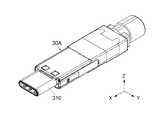
図1を参照すると、本発明の第1の実施の形態によるコネクタ組立体1は、コネクタ10と、相手側コネクタ80とを備えている。コネクタ10は、前後方向(X方向)に沿って前方(+X方向)に移動することで、相手側コネクタ80と嵌合可能である。本実施の形態によるコネクタ10は、ケーブル70に接続されたケーブルコネクタであり、相手側コネクタ80は、相手側回路基板890上に搭載された基板コネクタである。また、本実施の形態によるコネクタ10はプラグであり、相手側コネクタ80はレセプタクルである。但し、本発明は、これに限られず、様々なコネクタ及び相手側コネクタに適用可能である。例えば、相手側コネクタ80は、電子機器(図示せず)の一部であってもよい。
(First embodiment)
Referring to FIG. 1, the connector assembly 1 according to the first embodiment of the present invention includes a connector 10 and a mating connector 80. The connector 10 can be fitted to the mating connector 80 by moving forward (+ X direction) along the front-rear direction (X direction). Connector 10 according to the present embodiment is a cable connector connected to cable 70, and mating connector 80 is a board connector mounted on mating circuit board 890. The connector 10 according to the present embodiment is a plug, and the mating connector 80 is a receptacle. However, the present invention is not limited to this, and can be applied to various connectors and mating connectors. For example, the counterpart connector 80 may be a part of an electronic device (not shown).

図1及び図2を参照すると、相手側コネクタ80は、相手側嵌合部812と、2つの相手側ロック部(ロック孔)824とを備えている。詳しくは、相手側コネクタ80は、相手側コネクタ本体810と、金属製の相手側シェル820とを備えている。相手側嵌合部812は、相手側コネクタ本体810に設けられており、相手側ロック部824は、相手側シェル820に設けられている。相手側嵌合部812は、扁平な筒形状を有している。相手側嵌合部812の内部には、導電体からなる複数の相手側コンタクト814が設けられている。相手側コンタクト814は、ピッチ方向(Y方向:横方向)に配置されている。相手側コンタクト814は、相手側回路基板890に半田付け等によって接続され固定されている。   Referring to FIGS. 1 and 2, the mating connector 80 includes a mating mating portion 812 and two mating lock portions (lock holes) 824. Specifically, the mating connector 80 includes a mating connector body 810 and a metal mating shell 820. The mating mating portion 812 is provided in the mating connector main body 810, and the mating lock portion 824 is provided in the mating shell 820. The mating fitting portion 812 has a flat cylindrical shape. A plurality of mating contacts 814 made of a conductor are provided inside the mating mating portion 812. The counterpart contacts 814 are arranged in the pitch direction (Y direction: lateral direction). The mating contact 814 is connected and fixed to the mating circuit board 890 by soldering or the like.

相手側シェル820は、2つの側板822と、複数の被固定部828とを有している。相手側ロック部824は、側板822に夫々形成されている。本実施の形態による相手側ロック部824の夫々は、対応する側板822をY方向に貫通するロック孔である。相手側シェル820は、相手側コネクタ本体810を覆うようにして相手側回路基板890に取り付けられている。詳しくは、被固定部828は、相手側回路基板890に半田付け等によって接続され固定されている。これにより、相手側嵌合部812は、Y方向において、2つの相手側ロック部824の間に位置している。   The mating shell 820 includes two side plates 822 and a plurality of fixed portions 828. The mating lock portions 824 are formed on the side plates 822, respectively. Each of the mating lock portions 824 according to the present embodiment is a lock hole that penetrates the corresponding side plate 822 in the Y direction. The mating shell 820 is attached to the mating circuit board 890 so as to cover the mating connector body 810. Specifically, the fixed portion 828 is connected and fixed to the counterpart circuit board 890 by soldering or the like. Thereby, the other party fitting part 812 is located between the two other party lock parts 824 in the Y direction.

図3及び図4を参照すると、コネクタ10は、主部材20と、可動部材50と、操作部材60とを備えている。本実施の形態において、可動部材50は、主部材20の内部に少なくとも部分的に収容されている。また、操作部材60は、主部材20の内部に少なくとも部分的に収容されており、且つ、可動部材50の内部に少なくとも部分的に収容されている。   Referring to FIGS. 3 and 4, the connector 10 includes a main member 20, a movable member 50, and an operation member 60. In the present embodiment, the movable member 50 is at least partially housed inside the main member 20. The operation member 60 is at least partially accommodated in the main member 20 and is at least partially accommodated in the movable member 50.

主部材20は、コネクタ本体30と、絶縁体からなるフード40とを備えている。本実施の形態によるフード40は、互いに別体に形成された上フード410及び下フード460を上下に連結した組立体である。上フード410及び下フード460は、上下方向(Z方向)におけるフード40の上部(+Z側の部分)及び下部(−Z側の部分)に夫々位置している。フード40は、Y方向両側に夫々位置する2つの側部46を有している。この構造により、フード40の内部には、収容部48が形成されている。収容部48は、フード40をX方向に貫通する空間である。   The main member 20 includes a connector main body 30 and a hood 40 made of an insulator. The hood 40 according to the present embodiment is an assembly in which an upper hood 410 and a lower hood 460 that are formed separately from each other are connected vertically. The upper hood 410 and the lower hood 460 are respectively located at the upper part (the + Z side part) and the lower part (the -Z side part) of the hood 40 in the vertical direction (Z direction). The hood 40 has two side portions 46 positioned on both sides in the Y direction. With this structure, the accommodating portion 48 is formed inside the hood 40. The accommodating portion 48 is a space that penetrates the hood 40 in the X direction.

上述したように、本実施の形態によるフード40は、上フード410及び下フード460の2つの部材から構成されている。但し、本発明は、これに限られない。例えば、フード40は、1つの部材であってもよい。更に、フード40は、コネクタ本体30と一体に形成されていてもよい。   As described above, the hood 40 according to the present embodiment includes two members, the upper hood 410 and the lower hood 460. However, the present invention is not limited to this. For example, the hood 40 may be a single member. Furthermore, the hood 40 may be formed integrally with the connector main body 30.

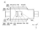
図3乃至図5を参照すると、コネクタ本体30は、嵌合部310を備えている。嵌合部310は、扁平な筒形状を有している。図23を参照すると、嵌合部310の内部には、導電体からなる複数のコンタクト320が設けられている。コンタクト320は、Y方向(ピッチ方向:横方向)に配置されている。コネクタ10の使用時において、コンタクト320は、ケーブル70(図5参照)に接続されている。図3乃至図5を参照すると、コネクタ本体30は、フード40によって保持されており、フード40に対して相対的に移動できない。詳しくは、コネクタ本体30は、嵌合部310と、ケーブル70に接続される後端部(−X側の端部)とを除いて、フード40の収容部48の内部に保持されている。嵌合部310は、フード40の前端(+X側の端)から前方に突出している。   Referring to FIGS. 3 to 5, the connector main body 30 includes a fitting portion 310. The fitting part 310 has a flat cylindrical shape. Referring to FIG. 23, a plurality of contacts 320 made of a conductor are provided inside the fitting portion 310. The contacts 320 are arranged in the Y direction (pitch direction: lateral direction). When the connector 10 is used, the contact 320 is connected to the cable 70 (see FIG. 5). 3 to 5, the connector body 30 is held by the hood 40 and cannot move relative to the hood 40. Specifically, the connector main body 30 is held inside the housing portion 48 of the hood 40 except for the fitting portion 310 and a rear end portion (−X side end portion) connected to the cable 70. The fitting part 310 protrudes forward from the front end (+ X side end) of the hood 40.

図1乃至図3を参照すると、嵌合部310は、コネクタ10と相手側コネクタ80とが互いに嵌合した嵌合状態において、相手側嵌合部812と嵌合する。本実施の形態における嵌合部310は、嵌合状態において、相手側嵌合部812の内部に挿入される。このとき、コンタクト320(図23参照)は、相手側コンタクト814と夫々接続する。   Referring to FIGS. 1 to 3, the fitting portion 310 is fitted with the mating fitting portion 812 in a fitting state where the connector 10 and the mating connector 80 are fitted to each other. The fitting part 310 in this Embodiment is inserted in the other party fitting part 812 in a fitting state. At this time, the contact 320 (see FIG. 23) is connected to the counterpart contact 814, respectively.

図6乃至図8から理解されるように、フード40は、上フード410及び下フード460を上下に連結した状態において、2つの操作規制孔412と、2つの仕切り壁420と、2つのガイド溝440とを有している。操作規制孔412の一方は、上フード410をZ方向に貫通する矩形の孔であり、操作規制孔412の他方は、下フード460をZ方向に貫通する矩形の孔である。2つの仕切り壁420は、収容部48のY方向両側に夫々位置している。ガイド溝440の一方は、+Y側の仕切り壁420と+Y側の側部46との間に形成された溝であり、前方に開口している。ガイド溝440の他方は、−Y側の仕切り壁420と−Y側の側部46との間に形成された溝であり、前方に開口している。   As can be understood from FIGS. 6 to 8, the hood 40 has two operation restriction holes 412, two partition walls 420, and two guide grooves in a state where the upper hood 410 and the lower hood 460 are vertically connected. 440. One of the operation restriction holes 412 is a rectangular hole that penetrates the upper hood 410 in the Z direction, and the other of the operation restriction holes 412 is a rectangular hole that penetrates the lower hood 460 in the Z direction. The two partition walls 420 are located on both sides of the accommodating portion 48 in the Y direction. One of the guide grooves 440 is a groove formed between the + Y side partition wall 420 and the + Y side side 46 and opens forward. The other of the guide grooves 440 is a groove formed between the -Y side partition wall 420 and the -Y side side 46 and opens forward.

フード40の仕切り壁420のY方向外側の面は、後述するように、維持部422として機能する。換言すれば、主部材20(図4参照)のフード40の収容部48には、Y方向両側に夫々位置する2つの維持部422が設けられている。維持部422の夫々は、X方向と斜交する傾斜面である前端部424と、XZ平面と平行に延びる後部426とを有している。   The surface on the outer side in the Y direction of the partition wall 420 of the hood 40 functions as a maintenance unit 422 as described later. In other words, the storage portion 48 of the hood 40 of the main member 20 (see FIG. 4) is provided with two maintaining portions 422 that are located on both sides in the Y direction. Each of the maintaining portions 422 includes a front end portion 424 that is an inclined surface that obliquely crosses the X direction, and a rear portion 426 that extends parallel to the XZ plane.

図4、図7及び図8を参照すると、フード40は、2つの前進操作規制部414と、2つの後退操作規制部416と、2つの前進規制部430とを備えている。前進操作規制部414は、夫々、操作規制孔412の前端に位置する内壁面であり、後退操作規制部416は、夫々、操作規制孔412の後端に位置する内壁面である。また、前進規制部430は、夫々、仕切り壁420の後端面である。   Referring to FIGS. 4, 7, and 8, the hood 40 includes two forward operation restricting portions 414, two reverse operation restricting portions 416, and two forward restricting portions 430. Each of the forward operation restricting portions 414 is an inner wall surface located at the front end of the operation restricting hole 412, and each of the backward operation restricting portions 416 is an inner wall surface located at the rear end of the operation restricting hole 412. Further, the forward restricting portions 430 are rear end surfaces of the partition wall 420, respectively.

図9及び図10を参照すると、可動部材50は、絶縁体からなる本体部材510と、金属等の弾性変形可能な部材からなる2つのロック部材560と、金属からなる2つのカバー部材580とを備えている。可動部材50は、X方向と平行な軸に対して180度回転対称な形状を有している。   Referring to FIGS. 9 and 10, the movable member 50 includes a main body member 510 made of an insulator, two lock members 560 made of an elastically deformable member such as metal, and two cover members 580 made of metal. I have. The movable member 50 has a 180-degree rotationally symmetric shape with respect to an axis parallel to the X direction.

本体部材510は、上部512と、下部514と、2つの側部516と、中空部518とを有している。上部512及び下部514は、本体部材510の上端及び下端に夫々位置しており、Z方向と直交する水平面(XY平面)上を延びている。2つの側部516は、本体部材510のY方向両側に夫々位置しており、上部512及び下部514をZ方向に連結している。中空部518は、上部512,下部514及び側部516によって囲まれた空間であり、前方及び後方(−X側)に開口している。側部516の夫々には、圧入溝522と、3つの圧入孔524とが形成されている。圧入溝522は、中空部518内に位置しており、後方に開口している。圧入孔524は、前方に開口している。   The body member 510 has an upper part 512, a lower part 514, two side parts 516, and a hollow part 518. The upper part 512 and the lower part 514 are respectively located at the upper end and the lower end of the main body member 510, and extend on a horizontal plane (XY plane) orthogonal to the Z direction. The two side parts 516 are respectively located on both sides of the main body member 510 in the Y direction, and connect the upper part 512 and the lower part 514 in the Z direction. The hollow portion 518 is a space surrounded by the upper portion 512, the lower portion 514, and the side portion 516, and opens forward and backward (−X side). A press-fit groove 522 and three press-fit holes 524 are formed in each of the side portions 516. The press-fitting groove 522 is located in the hollow portion 518 and opens rearward. The press-fitting hole 524 opens forward.

図9を参照すると、可動部材50は、2つの前進力受部532と、2つの後退力受部534とを備えている。前進力受部532は、本体部材510の上部512及び下部514に夫々設けられている。同様に、後退力受部534は、上部512及び下部514に夫々設けられている。詳しくは、前進力受部532の一方は、上部512の後端面から前方に凹んだ凹みの前端面であり、前進力受部532の他方は、下部514の後端面から前方に凹んだ凹みの前端面である。後退力受部534の一方は、上部512の前端面から後方に凹んだ凹みの後端面であり、後退力受部534の他方は、下部514の前端面から後方に凹んだ凹みの後端面である。   Referring to FIG. 9, the movable member 50 includes two forward force receiving portions 532 and two backward force receiving portions 534. The forward force receiving portions 532 are provided on the upper portion 512 and the lower portion 514 of the main body member 510, respectively. Similarly, the retracting force receiving portion 534 is provided in each of the upper part 512 and the lower part 514. Specifically, one of the forward force receiving portions 532 is a front end surface of a recess recessed forward from the rear end surface of the upper portion 512, and the other of the advance force receiving portions 532 is a recess recessed forward of the rear end surface of the lower portion 514. Front end face. One of the retracting force receiving portions 534 is a rear end surface of a recess recessed backward from the front end surface of the upper portion 512, and the other of the retracting force receiving portions 534 is a rear end surface of a recess recessed backward from the front end surface of the lower portion 514. is there.

図9乃至図11を参照すると、ロック部材560の夫々は、1枚の金属板を折り曲げて形成されている。換言すれば、ロック部材560の夫々は、曲げを有する一枚板である。本実施の形態において、2つのロック部材560は、互いに同一な形状を有している。換言すれば、2つのロック部材560は、同一の部品である。但し、ロック部材560の一方は、ロック部材560の他方に対して、X方向と平行な軸を中心にして180°回転した状態に配置されている。   9 to 11, each of the lock members 560 is formed by bending a single metal plate. In other words, each of the lock members 560 is a single plate having a bend. In the present embodiment, the two lock members 560 have the same shape. In other words, the two lock members 560 are the same part. However, one of the lock members 560 is arranged in a state of being rotated 180 ° around the axis parallel to the X direction with respect to the other of the lock members 560.

ロック部材560の夫々は、圧入部562と、支持部564と、被操作部566と、ロック部568とを有している。圧入部562は、ロック部材560の後端に位置している。支持部564は、圧入部562から前方に長く延びており、XY平面において弾性変形可能である。被操作部566は、X方向における支持部564の中間部に設けられており、Y方向内側に弧を描くように張り出している。換言すれば、被操作部566は、ロック部材560に形成された湾曲部である。ロック部568は、支持部564の前端に設けられており、Y方向内側に延びている。本実施の形態によるロック部568は、Y方向内側に延びるロック爪である。但し、ロック部568が延びる方向は、Y方向と多少斜交していてもよい。換言すれば、ロック部568は、X方向と交差する方向に延びていればよい。   Each of the lock members 560 includes a press-fit portion 562, a support portion 564, an operated portion 566, and a lock portion 568. The press-fit portion 562 is located at the rear end of the lock member 560. The support portion 564 extends long forward from the press-fit portion 562 and can be elastically deformed in the XY plane. The operated portion 566 is provided at an intermediate portion of the support portion 564 in the X direction, and projects so as to draw an arc on the inner side in the Y direction. In other words, the operated portion 566 is a curved portion formed on the lock member 560. The lock portion 568 is provided at the front end of the support portion 564 and extends inward in the Y direction. The lock portion 568 according to the present embodiment is a lock claw that extends inward in the Y direction. However, the direction in which the lock portion 568 extends may be slightly oblique to the Y direction. In other words, the lock portion 568 only needs to extend in a direction intersecting the X direction.

図9及び図10を参照すると、カバー部材580の夫々は、1枚の金属板を折り曲げて形成されている。換言すれば、カバー部材580の夫々は、曲げを有する一枚板である。本実施の形態において、2つのカバー部材580は、互いに同一な形状を有している。換言すれば、2つのカバー部材580は、同一の部品である。また、2つのカバー部材580は、XZ平面に対して鏡対称に配置されている。   9 and 10, each of the cover members 580 is formed by bending a single metal plate. In other words, each of the cover members 580 is a single plate having a bend. In the present embodiment, the two cover members 580 have the same shape. In other words, the two cover members 580 are the same part. Further, the two cover members 580 are arranged in mirror symmetry with respect to the XZ plane.

カバー部材580の夫々は、3つの圧入部582と、カバー584と、2つの前進被規制部590とを有している。また、カバー部材580の夫々には、受容部586が形成されている。圧入部582は、カバー部材580の後端に位置している。カバー584は、圧入部582から前方に長く延びており、Y方向内側及び後方に開口した箱形状を有している。前進被規制部590の夫々は、圧入部582が設けられた折り曲げ片の前端面である。受容部586は、カバー584に囲まれた空間であり、Y方向内側及び後方に開口している。   Each of the cover members 580 has three press-fit portions 582, a cover 584, and two forward restricted portions 590. Each cover member 580 is formed with a receiving portion 586. The press-fit portion 582 is located at the rear end of the cover member 580. The cover 584 extends long forward from the press-fit portion 582, and has a box shape that opens inward and rearward in the Y direction. Each of the forward restricted portions 590 is a front end surface of the bent piece provided with the press-fit portion 582. The receiving portion 586 is a space surrounded by the cover 584 and opens inward and rearward in the Y direction.

図9及び図10を参照すると、ロック部材560の圧入部562は、後方から本体部材510の圧入溝522に圧入されている。これにより、ロック部材560は、本体部材510に保持されており、支持部564は、本体部材510の前端から前方に突出している。カバー部材580の圧入部582は、前方から本体部材510の圧入孔524に圧入されている。これにより、カバー部材580は、本体部材510に保持されており、カバー584は、本体部材510の前端から前方に突出している。また、前進被規制部590は、本体部材510の前端よりも前方に位置している。   9 and 10, the press-fit portion 562 of the lock member 560 is press-fitted into the press-fit groove 522 of the main body member 510 from the rear. Thus, the lock member 560 is held by the main body member 510, and the support portion 564 protrudes forward from the front end of the main body member 510. The press-fitting portion 582 of the cover member 580 is press-fitted into the press-fitting hole 524 of the main body member 510 from the front. Accordingly, the cover member 580 is held by the main body member 510, and the cover 584 protrudes forward from the front end of the main body member 510. Further, the forward restricted portion 590 is located in front of the front end of the main body member 510.

図9を参照すると、支持部564の殆どは、受容部586内に受容されており、受容部586内において弾性変形が許容されている。ロック部568は、支持部564に支持されており、Y方向において移動可能である。図9及び図24を参照すると、支持部564が弾性変形していないバネの初期状態において、被操作部566の一部は、受容部586からY方向内側に突出している。また、バネの初期状態において、ロック部568の先端部は、受容部586からY方向内側に突出している。   Referring to FIG. 9, most of the support portion 564 is received in the receiving portion 586, and elastic deformation is allowed in the receiving portion 586. The lock part 568 is supported by the support part 564 and is movable in the Y direction. 9 and 24, in the initial state of the spring in which the support portion 564 is not elastically deformed, a part of the operated portion 566 protrudes inward in the Y direction from the receiving portion 586. In the initial state of the spring, the distal end portion of the lock portion 568 protrudes inward in the Y direction from the receiving portion 586.

図9を参照すると、本実施の形態による支持部564,被操作部566及びロック部568の夫々は、本体部材510と別体に形成されたロック部材560の一部である。換言すれば、可動部材50は、2つのロック部材560に夫々設けられた2つの支持部564と2つの被操作部566と2つのロック部568とを備えている。加えて、可動部材50は、2つのカバー部材580に夫々設けられた2つのカバー584と4つの前進被規制部590とを備えている。   Referring to FIG. 9, each of the support portion 564, the operated portion 566, and the lock portion 568 according to the present embodiment is a part of the lock member 560 formed separately from the main body member 510. In other words, the movable member 50 includes two support portions 564, two operated portions 566, and two lock portions 568 provided on the two lock members 560, respectively. In addition, the movable member 50 includes two covers 584 and four forward restricted portions 590 provided on the two cover members 580, respectively.

但し、本発明は、これに限られない。例えば、ロック部材560及びカバー部材580は、共通の1枚の金属板を折り曲げて形成してもよい。また、カバー部材580は、本体部材510の一部であってもよい。また、本体部材510,ロック部材560及びカバー部材580の全てを、共通の1枚の金属板を折り曲げて形成してもよい。また、例えばインサート成型によって、本体部材510,ロック部材560及びカバー部材580を、互いに一体に形成してもよい。   However, the present invention is not limited to this. For example, the lock member 560 and the cover member 580 may be formed by bending a common metal plate. Further, the cover member 580 may be a part of the main body member 510. Further, all of the main body member 510, the lock member 560, and the cover member 580 may be formed by bending a common metal plate. Further, the main body member 510, the lock member 560, and the cover member 580 may be integrally formed with each other by, for example, insert molding.

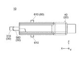
図12を参照すると、操作部材60は、X方向と平行な軸に対して180度回転対称な形状を有している。詳しくは、操作部材60は、上部602と、下部604と、2つの側部606と、中空部608とを有している。上部602及び下部604は、操作部材60の上端及び下端に夫々位置しており、概ねXY平面上を延びている。2つの側部606は、操作部材60のY方向両側に夫々位置しており、上部602及び下部604をZ方向に連結している。中空部608は、上部602,下部604及び側部606によって囲まれた空間であり、前方及び後方に開口している。図12、図22及び図23を参照すると、上部602及び下部604の夫々には、操作部610が設けられている。操作部610の一方は、上部602から上方に突出しており、操作部610の他方は、下部604から、下方に突出している。   Referring to FIG. 12, the operation member 60 has a 180-degree rotationally symmetric shape with respect to an axis parallel to the X direction. Specifically, the operation member 60 has an upper part 602, a lower part 604, two side parts 606, and a hollow part 608. The upper part 602 and the lower part 604 are located at the upper end and the lower end of the operation member 60, respectively, and generally extend on the XY plane. The two side portions 606 are respectively located on both sides of the operation member 60 in the Y direction, and connect the upper portion 602 and the lower portion 604 in the Z direction. The hollow part 608 is a space surrounded by the upper part 602, the lower part 604, and the side part 606, and is open forward and backward. Referring to FIGS. 12, 22, and 23, an operation unit 610 is provided in each of the upper part 602 and the lower part 604. One of the operation parts 610 protrudes upward from the upper part 602, and the other of the operation parts 610 protrudes downward from the lower part 604.

図12及び図15を参照すると、操作部材60は、2つの前進力付加部622と、2つの後退力付加部624と、2つの前進操作被規制部632と、2つの後退操作被規制部634と、2つの操作突部640とを備えている。前進力付加部622の一方は、上部602の後端近傍から上方に突出した突起の前端面であり、前進力付加部622の他方は、下部604の後端近傍から下方に突出した突起の前端面である。   Referring to FIGS. 12 and 15, the operation member 60 includes two forward force applying portions 622, two backward force adding portions 624, two forward operation restricted portions 632, and two backward operation restricted portions 634. And two operation protrusions 640. One of the advancing force adding portions 622 is a front end surface of a protrusion protruding upward from the vicinity of the rear end of the upper portion 602, and the other of the advancing force adding portions 622 is the front end of the protrusion protruding downward from the vicinity of the rear end of the lower portion 604. Surface.

本実施の形態においては、2つの操作部610の夫々の前面が前進操作被規制部632として機能し、操作部610の夫々の後面が後退力付加部624及び後退操作被規制部634として機能する。詳しくは、後退力付加部624の夫々は、対応する操作部610の後面の一部であり、後退操作被規制部634の夫々は、対応する操作部610の後面の他の一部である。また、前進操作被規制部632の夫々は、対応する操作部610の前面の一部である。   In the present embodiment, the front surfaces of the two operation portions 610 function as the forward operation restricted portion 632, and the rear surfaces of the operation portions 610 function as the backward force adding portion 624 and the backward operation restricted portion 634. . Specifically, each of the retraction force adding units 624 is a part of the rear surface of the corresponding operation unit 610, and each of the retraction operation restricted portions 634 is another part of the rear surface of the corresponding operation unit 610. Each of the forward operation restricted portions 632 is a part of the front surface of the corresponding operation portion 610.

図12を参照すると、操作突部640の一方は、+Y側の側部606の前端近傍から+Y方向に突出した突起であり、操作突部640の他方は、−Y側の側部606の前端近傍から−Y方向に突出した突起である。換言すれば、2つの操作突部640は、側部606に夫々設けられており、Y方向外側に突出している。操作突部640の夫々のY方向外側の面は、傾斜面642と、外側面644とから構成されている。傾斜面642は、X方向と斜交する面であり、操作突部640の後部(−X側の部位)に設けられている。外側面644は、XZ平面と平行な面であり、操作突部640の前部(+X側の部位)に設けられている。   Referring to FIG. 12, one of the operation protrusions 640 is a protrusion protruding in the + Y direction from the vicinity of the front end of the + Y side portion 606, and the other operation protrusion 640 is the front end of the −Y side portion 606. It is a protrusion protruding in the −Y direction from the vicinity. In other words, the two operation protrusions 640 are respectively provided on the side portions 606 and protrude outward in the Y direction. Each outer surface of the operation protrusion 640 in the Y direction includes an inclined surface 642 and an outer surface 644. The inclined surface 642 is a surface that obliquely intersects with the X direction, and is provided at the rear portion (the portion on the −X side) of the operation protrusion 640. The outer side surface 644 is a surface parallel to the XZ plane, and is provided at the front portion (the + X side portion) of the operation protrusion 640.

図3及び図4を参照すると、コネクタ10は、上述した主部材20,可動部材50及び操作部材60からなる組立体である。コネクタ10を組み立てる際、まず、操作部材60を、前方から可動部材50の中空部518に挿入し、前進力付加部622を、前進力受部532の後方に配置する。次に、主部材20のコネクタ本体30を、後方から操作部材60の中空部608に挿入する。次に、主部材20の上フード410及び下フード460によって、コネクタ本体30,可動部材50及び操作部材60を覆う。これにより、コネクタ本体30,可動部材50及び操作部材60は、少なくとも部分的に主部材20の収容部48内に収容され、2つのカバー部材580は、2つのガイド溝440に夫々受容される。このとき、コネクタ本体30の嵌合部310は、Y方向において、2つのロック部568の間に位置している(図14参照)。   3 and 4, the connector 10 is an assembly including the main member 20, the movable member 50, and the operation member 60 described above. When assembling the connector 10, first, the operation member 60 is inserted into the hollow portion 518 of the movable member 50 from the front, and the advance force adding portion 622 is disposed behind the advance force receiving portion 532. Next, the connector main body 30 of the main member 20 is inserted into the hollow portion 608 of the operation member 60 from the rear. Next, the connector main body 30, the movable member 50 and the operation member 60 are covered by the upper hood 410 and the lower hood 460 of the main member 20. Accordingly, the connector main body 30, the movable member 50, and the operation member 60 are at least partially accommodated in the accommodating portion 48 of the main member 20, and the two cover members 580 are received in the two guide grooves 440, respectively. At this time, the fitting portion 310 of the connector main body 30 is located between the two lock portions 568 in the Y direction (see FIG. 14).

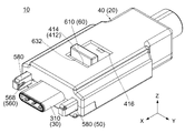
コネクタ10は、上述のように組み立てられたとき、図3及び図13乃至図16に示される初期状態にある。図14及び図15を参照すると、コネクタ10が初期状態にあるとき、可動部材50は、YZ平面において操作部材60及びコネクタ本体30を部分的に囲んでいる。詳しくは、可動部材50全体がフード40の収容部48の内部に収容されており、操作部材60は、操作部610を除いて収容部48の内部に収容されている。操作部610は、主部材20の外部に突出している。このため、操作部610にX方向に沿った力を加えることで、操作部材60を移動操作できる。特に、図15に示されるように、本実施の形態による操作部610は、上下に2つ設けられている。このため、操作者は、操作部610を上下に挟むことで、操作部材60をワンハンド操作できる。   The connector 10 is in the initial state shown in FIGS. 3 and 13 to 16 when assembled as described above. 14 and 15, when the connector 10 is in the initial state, the movable member 50 partially surrounds the operation member 60 and the connector main body 30 in the YZ plane. Specifically, the entire movable member 50 is housed in the housing portion 48 of the hood 40, and the operation member 60 is housed in the housing portion 48 except for the operation portion 610. The operation unit 610 protrudes outside the main member 20. For this reason, the operation member 60 can be moved and operated by applying a force along the X direction to the operation unit 610. In particular, as shown in FIG. 15, two operation units 610 according to the present embodiment are provided vertically. For this reason, the operator can operate the operation member 60 by one hand by pinching the operation part 610 up and down.

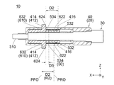
図13乃至図15を参照すると、初期状態において、操作部材60の後退操作被規制部634は、主部材20の後退操作規制部416の直前に位置している。このため、操作部材60(後退操作被規制部634)は、後方に移動できない。一方、操作部材60の前進操作被規制部632は、主部材20の前進操作規制部414から移動距離D2だけ離れて後方に位置している。また、X方向において、操作部材60と主部材20との間には、操作部材60の前方への移動を停止させる部位や部材が存在しない。このため、操作部材60(前進操作被規制部632)は、移動距離D2だけ前方に移動できる。   Referring to FIGS. 13 to 15, in the initial state, the backward operation restricted portion 634 of the operation member 60 is positioned immediately before the backward operation restriction portion 416 of the main member 20. For this reason, the operation member 60 (reverse operation restricted part 634) cannot move backward. On the other hand, the forward operation restricted portion 632 of the operating member 60 is located rearward from the forward operation restricting portion 414 of the main member 20 by a movement distance D2. Further, there is no portion or member that stops the forward movement of the operation member 60 between the operation member 60 and the main member 20 in the X direction. For this reason, the operation member 60 (the forward operation restricted portion 632) can move forward by the movement distance D2.

前進操作規制部414は、前進操作被規制部632の真っ直ぐ前方に位置している。このため、前進操作被規制部632は、移動距離D2だけ前方に移動したとき、前進操作規制部414と接触する。従って、前進操作被規制部632は、前進操作規制部414よりも前方に移動できない。一方、移動距離D2だけ前方に移動した前進操作被規制部632は、移動距離D2だけ後方に移動できる。   The forward operation restricting portion 414 is positioned directly in front of the forward operation restricted portion 632. For this reason, the forward operation restricted portion 632 contacts the forward operation restricting portion 414 when moving forward by the movement distance D2. Therefore, the forward operation restricted portion 632 cannot move forward relative to the forward operation restricted portion 414. On the other hand, the forward operation restricted portion 632 moved forward by the moving distance D2 can move backward by the moving distance D2.

以上の説明から理解されるように、前進操作被規制部632は、移動距離D2だけ前後に移動可能である。詳しくは、前進操作被規制部632は、X方向における所定の操作移動範囲R2の前端位置PFOと後端位置PROとの間を、主部材20に対して相対的に、移動距離D2だけ前後に移動可能である。前端位置PFOは、主部材20の前進操作規制部414のX方向における位置であり、後端位置PROは、後退操作被規制部634が主部材20の後退操作規制部416と接触しているときの、前進操作被規制部632のX方向における位置である。   As can be understood from the above description, the forward operation restricted portion 632 is movable back and forth by the movement distance D2. Specifically, the forward operation restricted portion 632 moves forward and backward by a movement distance D2 relative to the main member 20 between the front end position PFO and the rear end position PRO of the predetermined operation movement range R2 in the X direction. It is movable. The front end position PFO is a position in the X direction of the forward operation restricting portion 414 of the main member 20, and the rear end position PRO is when the reverse operation restricted portion 634 is in contact with the reverse operation restricting portion 416 of the main member 20. Of the forward operation restricted portion 632 in the X direction.

前進操作被規制部632は、操作部材60の一部である。従って、前進操作被規制部632が移動するとき、操作部材60全体が前進操作被規制部632の移動方向と同じ方向に同じ距離だけ移動する。以下、前進操作被規制部632の位置を、操作部材60の位置として説明する。即ち、操作部材60は、X方向における操作移動範囲R2の前端位置PFOと後端位置PROとの間を、主部材20に対して相対的に、前後に移動距離D2だけ移動可能である。前進操作規制部414は、操作部材60の前方への移動を規制して、操作移動範囲R2の前端位置PFOを規定している。また、後退操作規制部416は、操作部材60の後方への移動を規制して、操作移動範囲R2の後端位置PROを規定している。   The forward operation restricted portion 632 is a part of the operation member 60. Accordingly, when the forward operation restricted portion 632 moves, the entire operation member 60 moves by the same distance in the same direction as the moving direction of the forward operation restricted portion 632. Hereinafter, the position of the forward operation restricted portion 632 will be described as the position of the operation member 60. That is, the operation member 60 is movable back and forth by a movement distance D2 relative to the main member 20 between the front end position PFO and the rear end position PRO of the operation movement range R2 in the X direction. The forward operation restricting unit 414 restricts the forward movement of the operation member 60 and defines the front end position PFO of the operation movement range R2. Further, the backward operation restricting section 416 restricts the backward movement of the operation member 60 and defines the rear end position PRO of the operation movement range R2.

図14を参照すると、初期状態において、可動部材50の後端は、フード40の内壁の一部の直前に位置している。このため、可動部材50は、後方に移動できない。一方、可動部材50の前進被規制部590は、主部材20の前進規制部430から移動距離D1だけ離れて後方に位置している。また、X方向において、可動部材50と主部材20との間には、操作部材60を除き可動部材50の前方への移動を停止させる部位や部材が存在しない。また、操作部材60は、主部材20に対して相対的に移動可能である。このため、可動部材50(前進被規制部590)は、移動距離D1だけ前方に移動できる。   Referring to FIG. 14, the rear end of the movable member 50 is located immediately before a part of the inner wall of the hood 40 in the initial state. For this reason, the movable member 50 cannot move backward. On the other hand, the forward restricted portion 590 of the movable member 50 is located rearward from the forward restricting portion 430 of the main member 20 by a movement distance D1. Further, in the X direction, there is no portion or member between the movable member 50 and the main member 20 that stops the forward movement of the movable member 50 except for the operation member 60. In addition, the operation member 60 is movable relative to the main member 20. For this reason, the movable member 50 (advanced regulated part 590) can move forward by the movement distance D1.

前進規制部430は、前進被規制部590の真っ直ぐ前方に位置している。このため、前進被規制部590は、移動距離D1だけ前方に移動したとき、前進規制部430と接触する。従って、前進被規制部590は、前進規制部430よりも前方に移動できない。一方、移動距離D1だけ前方に移動した前進被規制部590は、移動距離D1だけ後方に移動できる。   The forward restricting portion 430 is positioned directly in front of the forward restricted portion 590. For this reason, the forward restricted part 590 comes into contact with the forward restricting part 430 when moving forward by the movement distance D1. Therefore, the forward restricted portion 590 cannot move forward than the forward restricting portion 430. On the other hand, the forward restricted portion 590 that has moved forward by the moving distance D1 can move backward by the moving distance D1.

以上の説明から理解されるように、前進被規制部590は、移動距離D1だけ前後に移動可能である。詳しくは、前進被規制部590は、X方向における所定の移動範囲R1の前端位置PFと後端位置PRとの間を、主部材20に対して相対的に、移動距離D1だけ前後に移動可能である。前端位置PFは、主部材20の前進規制部430のX方向における位置であり、後端位置PRは、可動部材50の後端がフード40の内壁に接触しているときの、前進被規制部590のX方向における位置である。   As can be understood from the above description, the forward restricted portion 590 can move back and forth by the moving distance D1. Specifically, the forward restricted portion 590 can move back and forth between the front end position PF and the rear end position PR of the predetermined movement range R1 in the X direction by a movement distance D1 relative to the main member 20. It is. The front end position PF is a position in the X direction of the forward movement restricting portion 430 of the main member 20, and the rear end position PR is the forward restricted portion when the rear end of the movable member 50 is in contact with the inner wall of the hood 40. 590 is the position in the X direction.

前進被規制部590は、可動部材50の一部である。従って、前進被規制部590が移動するとき、可動部材50全体が前進被規制部590の移動方向と同じ方向に同じ距離だけ移動する。以下、前進被規制部590の位置を、可動部材50の位置として説明する。即ち、可動部材50は、X方向における移動範囲R1の前端位置PFと後端位置PRとの間を、主部材20に対して相対的に、前後に移動距離D1だけ移動可能である。前進規制部430は、可動部材50の前方への移動を規制して、移動範囲R1の前端位置PFを規定している。また、フード40の内壁のうち可動部材50の後端と接触する部位(後退規制部)は、可動部材50の後方への移動を規制して、移動範囲R1の後端位置PRを規定している。   The forward restricted portion 590 is a part of the movable member 50. Therefore, when the forward restricted portion 590 moves, the entire movable member 50 moves by the same distance in the same direction as the moving direction of the forward restricted portion 590. Hereinafter, the position of the forward restricted portion 590 will be described as the position of the movable member 50. That is, the movable member 50 can move back and forth between the front end position PF and the rear end position PR of the movement range R1 in the X direction by the movement distance D1 relative to the main member 20. The forward regulation part 430 regulates the forward movement of the movable member 50 and defines the front end position PF of the movement range R1. Further, a portion of the inner wall of the hood 40 that comes into contact with the rear end of the movable member 50 (retraction restricting portion) regulates the rearward movement of the movable member 50 and defines the rear end position PR of the movement range R1. Yes.

図1を参照すると、上述した初期状態にあるコネクタ10全体を相手側コネクタ80に向かって移動させると、嵌合部310が相手側嵌合部812に挿入され、コンタクト320(図23参照)が相手側コンタクト814(図2参照)と夫々接続する。このとき、コネクタ10を後方に引くだけで相手側コネクタ80から抜去できる。換言すれば、コネクタ10は、その初期状態を維持したまま、相手側コネクタ80と嵌合した嵌合状態になる。以下、コネクタ10と相手側コネクタ80との嵌合状態をロックするための操作及び嵌合状態のロックを解除するための操作について説明する。   Referring to FIG. 1, when the entire connector 10 in the initial state described above is moved toward the mating connector 80, the fitting portion 310 is inserted into the mating fitting portion 812, and the contact 320 (see FIG. 23) is inserted. Each is connected to a counterpart contact 814 (see FIG. 2). At this time, the connector 10 can be removed from the mating connector 80 simply by pulling the connector 10 backward. In other words, the connector 10 is in a fitted state in which the connector 10 is fitted with the mating connector 80 while maintaining its initial state. Hereinafter, an operation for locking the fitting state between the connector 10 and the mating connector 80 and an operation for releasing the locking of the fitting state will be described.

図15を参照すると、初期状態において、可動部材50の後退力受部534は、操作部材60の後退力付加部624の直後に位置しており、後退力付加部624と接触している。一方、可動部材50の前進力受部532は、操作部材60の前進力付加部622の真っ直ぐ前方に位置している。   Referring to FIG. 15, in the initial state, the retracting force receiving portion 534 of the movable member 50 is positioned immediately after the retracting force adding portion 624 of the operation member 60 and is in contact with the retracting force adding portion 624. On the other hand, the forward force receiving portion 532 of the movable member 50 is positioned directly in front of the forward force adding portion 622 of the operation member 60.

詳しくは、図18を参照すると、X方向と直交する直交平面(YZ平面)における前進力付加部622の位置は、YZ平面における前進力受部532の位置と重なっている。また、図14及び図15を参照すると、操作部材60が操作移動範囲R2の後端位置PROに位置し、且つ、可動部材50が移動範囲R1の後端位置PRに位置しているとき(即ち、初期状態において)、前進力付加部622は、前進力受部532から後方に所定距離D3だけ離れてX方向において前進力受部532と対向している。所定距離D3は、移動距離D2よりも小さい。このため、操作部材60を操作移動範囲R2の後端位置PROから前方に所定距離D3だけ移動すると、前進力付加部622は、前進力受部532と接触する。   Specifically, referring to FIG. 18, the position of the advancing force adding portion 622 in the orthogonal plane (YZ plane) orthogonal to the X direction overlaps with the position of the advancing force receiving portion 532 in the YZ plane. 14 and 15, when the operation member 60 is located at the rear end position PRO of the operation movement range R2 and the movable member 50 is located at the rear end position PR of the movement range R1 (ie, In the initial state), the forward force adding portion 622 is separated from the forward force receiving portion 532 rearward by a predetermined distance D3 and faces the forward force receiving portion 532 in the X direction. The predetermined distance D3 is smaller than the movement distance D2. For this reason, when the operation member 60 is moved forward from the rear end position PRO of the operation movement range R2 by a predetermined distance D3, the advance force adding unit 622 comes into contact with the advance force receiving unit 532.

前進力付加部622が前進力受部532と接触したとき、コネクタ10は、図17及び図18に示される中間状態にある。   When the advancing force adding portion 622 comes into contact with the advancing force receiving portion 532, the connector 10 is in an intermediate state shown in FIGS.

図14及び図16を参照すると、主部材20の維持部422は、その前端部424を除き、操作部材60の操作突部640を越えてY方向外側に位置している。また、初期状態において、維持部422の後端は、可動部材50の被操作部566の湾曲した頂点を越えて後方に位置している。このため、可動部材50の支持部564は、Y方向外側に弾性変形している。詳しくは、被操作部566は、維持部422のY方向外側に位置しており、操作突部640からY方向外側に離れている。従って、操作部材60が後端位置PROから前方に所定距離D3だけ移動する間、操作部材60は、被操作部566に力を加えない。   Referring to FIGS. 14 and 16, the maintenance portion 422 of the main member 20 is located on the outer side in the Y direction beyond the operation protrusion 640 of the operation member 60 except for the front end portion 424 thereof. Further, in the initial state, the rear end of the maintenance unit 422 is positioned behind the curved vertex of the operated portion 566 of the movable member 50. For this reason, the support portion 564 of the movable member 50 is elastically deformed outward in the Y direction. Specifically, the operated portion 566 is located outside the maintaining portion 422 in the Y direction, and is separated from the operation protrusion 640 outward in the Y direction. Therefore, the operation member 60 does not apply force to the operated portion 566 while the operation member 60 moves forward from the rear end position PRO by the predetermined distance D3.

以上の説明から理解されるように、維持部422のうち、可動部材50が後端位置PRの近傍にあるときに被操作部566のY方向内側に位置する部位は、被操作部566を仮保持する仮保持部450として機能する。換言すれば、維持部422には、仮保持部450が設けられている。仮保持部450は、操作部材60の操作突部640を越えてY方向外側に位置している。操作部材60が操作移動範囲R2の後端位置PROに位置しているとき、被操作部566は、Y方向において仮保持部450の外側に位置している。   As can be understood from the above description, a portion of the maintenance unit 422 that is located on the inner side in the Y direction of the operated unit 566 when the movable member 50 is in the vicinity of the rear end position PR. It functions as the temporary holding part 450 to hold. In other words, the maintenance unit 422 is provided with the temporary holding unit 450. The temporary holding portion 450 is located outside the operation protrusion 640 of the operation member 60 and outside in the Y direction. When the operation member 60 is located at the rear end position PRO of the operation movement range R2, the operated portion 566 is located outside the temporary holding portion 450 in the Y direction.

仮保持部450の仮保持により、操作部材60が操作移動範囲R2の後端位置PROから前方に所定距離D3だけ移動する間、可動部材50は、移動範囲R1の後端位置PRに維持される。従って、操作部材60は、主部材20に対して相対的に移動すると共に、可動部材50に対して相対的に移動する。換言すれば、操作部材60は、可動部材50に対して相対的に、X方向において所定距離D3だけ前方に移動可能である。   By temporarily holding the temporary holding portion 450, the movable member 50 is maintained at the rear end position PR of the movement range R1 while the operation member 60 moves forward by a predetermined distance D3 from the rear end position PRO of the operation movement range R2. . Therefore, the operation member 60 moves relative to the main member 20 and moves relative to the movable member 50. In other words, the operation member 60 can move forward by a predetermined distance D3 in the X direction relative to the movable member 50.

図15及び図18を参照すると、後端位置PROから所定距離D3だけ前方に位置した操作部材60を更に前方に移動すると、前進力付加部622は、前進力受部532に前方に向かう前進力を付加する。可動部材50は、前進力により、操作部材60と共に前方に移動する。図19及び図21を参照すると、操作部材60を前方に移動し続けると、操作部材60の前進操作被規制部632が主部材20の前進操作規制部414に突き当たり、操作部材60は主部材20に対して停止する。   Referring to FIGS. 15 and 18, when the operation member 60 positioned forward by a predetermined distance D3 from the rear end position PRO is further moved forward, the forward force adding unit 622 advances the forward force toward the forward force receiving unit 532. Is added. The movable member 50 moves forward together with the operation member 60 by forward force. Referring to FIGS. 19 and 21, when the operation member 60 continues to move forward, the forward operation restricted portion 632 of the operation member 60 hits the forward operation restriction portion 414 of the main member 20, and the operation member 60 is moved to the main member 20. Stop against.

前進操作被規制部632が前進操作規制部414に突き当たったとき、コネクタ10は、図19乃至図25に示されるロック状態にある。   When the forward operation restricted portion 632 hits the forward operation restricting portion 414, the connector 10 is in the locked state shown in FIGS.

図25を参照すると、ロック状態において、操作部材60は、操作移動範囲R2の前端位置PFOに位置する。図20及び図24を参照すると、このとき可動部材50は、移動範囲R1の前端位置PFに位置し、可動部材50の前進被規制部590は、主部材20の前進規制部430の直後に位置する。これにより、可動部材50だけが更に前方に移動することが防止されている。   Referring to FIG. 25, in the locked state, the operation member 60 is located at the front end position PFO of the operation movement range R2. 20 and 24, at this time, the movable member 50 is located at the front end position PF of the movement range R1, and the forward restricted portion 590 of the movable member 50 is located immediately after the forward restricting portion 430 of the main member 20. To do. Thereby, only the movable member 50 is prevented from moving further forward.

図24を参照すると、ロック状態において、可動部材50の被操作部566は、主部材20の維持部422の後部426の前方に位置しており、維持部422と接触していない。また、被操作部566は、操作突部640の外側面644の後方に位置しており、操作突部640と接触していない。このため、被操作部566は、Y方向外側に向かう力を受けず、弾性変形していた支持部564は、バネの初期状態に復帰する。この結果、図19、図21、図23及び図24に示されるように、ロック部568は、カバー584の受容部586からY方向内側に突出する。   Referring to FIG. 24, in the locked state, the operated portion 566 of the movable member 50 is located in front of the rear portion 426 of the maintaining portion 422 of the main member 20 and is not in contact with the maintaining portion 422. The operated portion 566 is located behind the outer surface 644 of the operation protrusion 640 and is not in contact with the operation protrusion 640. For this reason, the operated portion 566 does not receive a force toward the outside in the Y direction, and the support portion 564 that has been elastically deformed returns to the initial state of the spring. As a result, as shown in FIGS. 19, 21, 23, and 24, the lock portion 568 protrudes inward in the Y direction from the receiving portion 586 of the cover 584.

図24を参照すると、カバー584から突出したロック部568の先端部は、嵌合状態にある相手側コネクタ80の相手側ロック部824の内部に位置する。これにより、コネクタ10の、相手側コネクタ80からの抜去が防止される。換言すれば、嵌合状態において操作部材60が操作移動範囲R2の前端位置PFOに位置し(図25参照)且つ可動部材50が移動範囲R1の前端位置PFに位置しているとき、ロック部568は、相手側ロック部824と共に嵌合状態をロックしている。特に、ロック部568の後端縁は、嵌合状態においてY方向に沿って延びている。このため、例えば、コネクタ10全体を後方に引いたとしても、ロック部568の後端縁が相手側ロック部824の後端縁に突き当たり、嵌合状態が維持される。   Referring to FIG. 24, the distal end portion of the lock portion 568 protruding from the cover 584 is located inside the mating lock portion 824 of the mating connector 80 in the fitted state. This prevents the connector 10 from being removed from the mating connector 80. In other words, when the operation member 60 is located at the front end position PFO of the operation movement range R2 (see FIG. 25) and the movable member 50 is located at the front end position PF of the movement range R1 in the fitted state, the lock portion 568. Locks the mating state together with the counterpart lock portion 824. In particular, the rear end edge of the lock portion 568 extends along the Y direction in the fitted state. For this reason, for example, even if the entire connector 10 is pulled rearward, the rear end edge of the lock portion 568 hits the rear end edge of the counterpart lock portion 824, and the fitting state is maintained.

図25を参照すると、ロック状態において、可動部材50の後退力受部534は、操作部材60の後退力付加部624の真っ直ぐ後方に位置している。詳しくは、図20を参照すると、YZ平面における後退力付加部624の位置は、YZ平面における後退力受部534の位置と重なっている。また、図24及び図25を参照すると、操作部材60が操作移動範囲R2の前端位置PFOに位置し、且つ、可動部材50が移動範囲R1の前端位置PFに位置しているとき、後退力付加部624は、後退力受部534から前方に所定距離D3だけ離れてX方向において後退力受部534と対向している。このため、操作部材60を操作移動範囲R2の前端位置PFOから後方に所定距離D3だけ移動すると、後退力付加部624は、後退力受部534と接触する。   Referring to FIG. 25, in the locked state, the retracting force receiving portion 534 of the movable member 50 is located directly behind the retracting force adding portion 624 of the operation member 60. Specifically, referring to FIG. 20, the position of the retraction force adding unit 624 in the YZ plane overlaps the position of the retraction force receiving unit 534 in the YZ plane. 24 and 25, when the operation member 60 is located at the front end position PFO of the operation movement range R2 and the movable member 50 is located at the front end position PF of the movement range R1, a reverse force is applied. The part 624 is separated from the retracting force receiving part 534 by a predetermined distance D3 and faces the retracting force receiving part 534 in the X direction. For this reason, when the operation member 60 is moved rearward from the front end position PFO of the operation movement range R2 by the predetermined distance D3, the retraction force adding unit 624 contacts the retraction force receiving unit 534.

後退力付加部624が後退力受部534と接触したとき、コネクタ10は、図26乃至図29に示されるアンロック状態にある。   When the retracting force adding portion 624 comes into contact with the retracting force receiving portion 534, the connector 10 is in the unlocked state shown in FIGS.

図24及び図25を参照すると、操作部材60が操作移動範囲R2の前端位置PFOから後方に所定距離D3だけ移動する間、可動部材50は、移動範囲R1の前端位置PFに維持される。従って、操作部材60は、主部材20に対して相対的に移動すると共に、可動部材50に対して相対的に移動する。換言すれば、操作部材60は、可動部材50に対して相対的に、X方向において所定距離D3だけ後方に移動可能である。   24 and 25, the movable member 50 is maintained at the front end position PF of the movement range R1 while the operation member 60 moves backward by a predetermined distance D3 from the front end position PFO of the operation movement range R2. Therefore, the operation member 60 moves relative to the main member 20 and moves relative to the movable member 50. In other words, the operation member 60 is movable backward by the predetermined distance D3 in the X direction relative to the movable member 50.

図24、図25及び図28を参照すると、操作部材60が前端位置PFOから後方に所定距離D3だけ移動する間、操作部材60の操作突部640の傾斜面642が可動部材50の被操作部566に接触し、被操作部566をY方向外側に押圧する。これにより、支持部564は、Y方向外側に弾性変形し、ロック部568は、Y方向外側に移動する。操作部材60が、前端位置PFOから後方に所定距離D3だけ離れた位置にあるとき、被操作部566は、操作突部640の外側面644上に位置する。   24, 25 and 28, while the operation member 60 moves rearward from the front end position PFO by a predetermined distance D3, the inclined surface 642 of the operation protrusion 640 of the operation member 60 is the operated portion of the movable member 50. 566 is touched and the operated portion 566 is pressed outward in the Y direction. As a result, the support portion 564 is elastically deformed outward in the Y direction, and the lock portion 568 moves outward in the Y direction. When the operation member 60 is at a position away from the front end position PFO by a predetermined distance D3, the operated portion 566 is positioned on the outer surface 644 of the operation protrusion 640.

換言すれば、嵌合状態において操作部材60が操作移動範囲R2の前端位置PFOから所定距離D3だけ後方に位置し且つ可動部材50が移動範囲R1の前端位置PFに位置しているとき、被操作部566は、Y方向において操作突部640の外側に位置している。この結果、ロック部568は、Y方向において相手側ロック部824の外側に移動して嵌合状態のロックを解除している。嵌合状態のロックが解除されたとき、ロック部568は、カバー584内に受容される。   In other words, when the operating member 60 is positioned rearward from the front end position PFO of the operation movement range R2 by the predetermined distance D3 and the movable member 50 is positioned at the front end position PF of the movement range R1 in the fitted state. The part 566 is located outside the operation protrusion 640 in the Y direction. As a result, the lock portion 568 moves to the outside of the counterpart lock portion 824 in the Y direction to release the lock in the fitted state. When the lock in the fitted state is released, the lock portion 568 is received in the cover 584.

本実施の形態によれば、可動部材50を移動範囲R1の前端位置PFに位置させたまま、操作部材60を操作移動範囲R2の前端位置PFOから所定距離D3だけ後方に位置させると、嵌合状態のロックが解除される。これにより、可動部材50を後方に移動させることなく、従って、ロック部568を相手側ロック部824の後端縁と突き当てることなく、嵌合状態のロックを解除できる。   According to the present embodiment, when the operating member 60 is positioned rearward from the front end position PFO of the operation movement range R2 by the predetermined distance D3 while the movable member 50 is positioned at the front end position PF of the movement range R1, the fitting is performed. The state lock is released. Thus, the locked state of the fitted state can be released without moving the movable member 50 rearward and, therefore, without causing the lock portion 568 to abut against the rear end edge of the counterpart lock portion 824.

図27乃至図29を参照すると、前端位置PFOから所定距離D3だけ後方に位置した操作部材60を更に後方に移動すると、後退力付加部624は、後退力受部534に後方に向かう後退力を付加する。可動部材50は、後退力により、操作部材60と共に後方に移動する。   Referring to FIGS. 27 to 29, when the operation member 60 positioned rearward from the front end position PFO by a predetermined distance D3 is further moved rearward, the retraction force adding unit 624 applies a retreating force toward the rear to the retraction force receiving unit 534. Append. The movable member 50 moves rearward together with the operation member 60 by a retreating force.

図28から理解されるように、操作部材60が前端位置PFOから所定距離D3だけ後方に離れた位置から更に後方に所定付加距離D4だけ移動すると、可動部材50の被操作部566は、維持部422の後部426上に乗り上げる。これにより、ロック部568がカバー584内に受容された状態が維持される。換言すれば、操作部材60が操作移動範囲R2の前端位置PFOから所定距離D3を所定付加距離D4だけ超えて後方に位置し且つ可動部材50が移動範囲R1の前端位置PFから所定付加距離D4だけ後方に位置しているとき、被操作部566は、Y方向において維持部422の外側に位置し、ロック部568のY方向外側に移動した状態が維持されている。   As understood from FIG. 28, when the operation member 60 moves further rearward from the front end position PFO by a predetermined distance D3 by a predetermined additional distance D4, the operated portion 566 of the movable member 50 becomes the maintenance portion. Ride on the rear 426 of the 422. Thereby, the state in which the lock portion 568 is received in the cover 584 is maintained. In other words, the operating member 60 is positioned rearward from the front end position PFO of the operation movement range R2 by exceeding the predetermined distance D3 by the predetermined additional distance D4, and the movable member 50 is only the predetermined additional distance D4 from the front end position PF of the movement range R1. When positioned rearward, the operated portion 566 is positioned outside the maintaining portion 422 in the Y direction, and the state where the operated portion 566 is moved outward in the Y direction of the lock portion 568 is maintained.

図27乃至図29を図13乃至図15と併せて参照すると、操作部材60を後方に移動し続けると、操作部材60の後退操作被規制部634が主部材20の後退操作規制部416と接触し、操作部材60は、操作移動範囲R2の後端位置PROに位置する。図14を参照すると、本実施の形態によれば、操作部材60が操作移動範囲R2の後端位置PROに位置したとき、可動部材50の後端は、フード40の内壁面と接触し、移動範囲R1の後端位置PRに位置する。このとき、コネクタ10は、図3及び図13乃至図16に示される初期状態にある。   Referring to FIGS. 27 to 29 together with FIGS. 13 to 15, when the operation member 60 continues to move backward, the retraction operation restricted portion 634 of the operation member 60 contacts the retraction operation restriction portion 416 of the main member 20. The operation member 60 is located at the rear end position PRO of the operation movement range R2. Referring to FIG. 14, according to the present embodiment, when the operation member 60 is positioned at the rear end position PRO of the operation movement range R2, the rear end of the movable member 50 comes into contact with the inner wall surface of the hood 40 and moves. It is located at the rear end position PR of the range R1. At this time, the connector 10 is in an initial state shown in FIGS. 3 and 13 to 16.

コネクタ10が初期状態にあるとき、操作部材60を更に後方に移動し続けると、コネクタ10は、相手側コネクタ80(図1参照)から抜去される。   When the connector 10 is in the initial state, the connector 10 is removed from the mating connector 80 (see FIG. 1) when the operation member 60 continues to move backward.

図14を参照すると、本実施の形態において、操作移動範囲R2における前端位置PFOと後端位置PROとの間の操作部材60の移動距離D2は、移動範囲R1における前端位置PFと後端位置PRとの間の可動部材50の移動距離D1+所定距離D3である。   Referring to FIG. 14, in the present embodiment, the movement distance D2 of the operation member 60 between the front end position PFO and the rear end position PRO in the operation movement range R2 is the front end position PF and the rear end position PR in the movement range R1. The movement distance D1 of the movable member 50 between and a predetermined distance D3.

特に、本実施の形態による可動部材50は、操作部材60が操作移動範囲R2の後端位置PROに位置しているときに後端位置PRに位置しており、後端位置PRを越えて後方に移動できない。これにより、可動部材50は、操作部材60を前方に移動しない限り、移動範囲R1の後端位置PRに維持される。従って、収容部48内での可動部材50の不要な移動が防止される。また、可動部材50は、操作部材60が操作移動範囲R2の前端位置PFOに位置しているときに前端位置PFに位置しており、前端位置PFを越えて前方に移動できない。即ち、本実施の形態における移動距離D1は、可動部材50が前後方向において実際に移動可能な距離(移動可能距離D5)と等しい。詳しくは、前端位置PF及び後端位置PRは、移動可能距離D5を有する移動範囲の前端位置及び後端位置と夫々一致している。   In particular, the movable member 50 according to the present embodiment is located at the rear end position PR when the operation member 60 is located at the rear end position PRO of the operation movement range R2, and is rearward beyond the rear end position PR. Cannot move to. Accordingly, the movable member 50 is maintained at the rear end position PR of the movement range R1 unless the operation member 60 is moved forward. Therefore, unnecessary movement of the movable member 50 in the accommodating portion 48 is prevented. The movable member 50 is located at the front end position PF when the operation member 60 is located at the front end position PFO of the operation movement range R2, and cannot move forward beyond the front end position PF. That is, the moving distance D1 in the present embodiment is equal to the distance that the movable member 50 can actually move in the front-rear direction (movable distance D5). Specifically, the front end position PF and the rear end position PR coincide with the front end position and the rear end position of the movement range having the movable distance D5, respectively.

但し、本発明は、これに限られない。例えば、可動部材50の後端位置PRから後方への多少の移動が許容されていてもよい。換言すれば、可動部材50は、操作移動範囲R2の後端位置PROに位置する操作部材60に対して、相対的に後方に移動可能であってもよい。同様に、可動部材50は、操作移動範囲R2の前端位置PFOに位置する操作部材60に対して、相対的に前方に移動可能であってもよい。即ち、操作部材60の操作移動範囲R2における移動距離D2は、可動部材50の移動範囲R1における移動可能距離D5+所定距離D3より小さくてもよい。   However, the present invention is not limited to this. For example, a slight movement backward from the rear end position PR of the movable member 50 may be allowed. In other words, the movable member 50 may be movable rearward relative to the operation member 60 located at the rear end position PRO of the operation movement range R2. Similarly, the movable member 50 may be able to move relatively forward with respect to the operation member 60 located at the front end position PFO of the operation movement range R2. That is, the movement distance D2 in the operation movement range R2 of the operation member 60 may be smaller than the movable distance D5 in the movement range R1 of the movable member 50 + the predetermined distance D3.

図14を参照すると、コネクタ10は、支持部564とロック部568とを含むロック機構を備えている。このロック機構は、可動部材50に設けられている。可動部材50は、X方向における移動範囲R1の前端位置PFと後端位置PRとの間を、嵌合部310が設けられた主部材20に対して相対的に移動可能である。このため、ロック機構は、X方向に沿って移動可能である。図31及び図32を参照すると、この構造により、コネクタ10は、相手側コネクタ80が筐体880の内部に設置されていても、相手側コネクタ80と嵌合可能である。   Referring to FIG. 14, the connector 10 includes a lock mechanism including a support portion 564 and a lock portion 568. This locking mechanism is provided on the movable member 50. The movable member 50 is movable relative to the main member 20 provided with the fitting portion 310 between the front end position PF and the rear end position PR of the movement range R1 in the X direction. For this reason, the lock mechanism is movable along the X direction. With reference to FIGS. 31 and 32, this structure allows the connector 10 to be fitted to the mating connector 80 even when the mating connector 80 is installed inside the housing 880.

図31を参照すると、例えば、コネクタ10を、相手側ロック部824を備える相手側コネクタ80と嵌合する場合であって、且つ、筐体880にカバー部材580の通過を許容する取付孔882が形成されている場合、可動部材50を移動範囲R1の前端位置PFに位置させることで嵌合状態をロックできる。   Referring to FIG. 31, for example, when the connector 10 is fitted to the mating connector 80 including the mating lock portion 824, the housing 880 has a mounting hole 882 that allows the cover member 580 to pass therethrough. If formed, the fitted state can be locked by positioning the movable member 50 at the front end position PF of the movement range R1.

図32を参照すると、例えば、コネクタ10を、相手側ロック部824を備えない相手側コネクタ80Xと嵌合する場合であって、且つ、筐体880にカバー部材580の通過を許容しない取付孔884が形成されている場合、可動部材50を移動範囲R1の後端位置PRに位置することで、コネクタ10を相手側コネクタ80Xと嵌合できる。換言すれば、本発明によるコネクタは、コネクタを相手側コネクタに嵌合する際のコネクタの移動経路上にロック機構と干渉する部位や部材が設けられていたとしても、相手側コネクタと嵌合可能である。   Referring to FIG. 32, for example, when the connector 10 is fitted with a mating connector 80X that does not include the mating lock portion 824, and the mounting hole 884 that does not allow the cover 580 to pass through the housing 880. When the movable member 50 is positioned at the rear end position PR of the movement range R1, the connector 10 can be fitted to the mating connector 80X. In other words, the connector according to the present invention can be mated with the mating connector even if a portion or member that interferes with the locking mechanism is provided on the movement path of the connector when mating the connector with the mating connector. It is.

本実施の形態は、既に説明した変形例に加えて、更に様々に変形可能である。   The present embodiment can be modified in various ways in addition to the modifications already described.

例えば、図16及び図30を参照すると、コネクタ10は、維持部422の一部である仮保持部450に代えて、仮保持部(リブ)450Xを備えていてもよい。換言すれば、図30に示されるように、維持部422には、仮保持部として機能するリブが設けられていてもよい。図示された仮保持部450Xは、操作部材60の操作突部640を越えてY方向外側に突出している。また、操作部材60が操作移動範囲R2の後端位置PROに位置しているとき、仮保持部450Xは、被操作部566の前方を部分的に塞いでいる。   For example, referring to FIGS. 16 and 30, the connector 10 may include a temporary holding portion (rib) 450 </ b> X instead of the temporary holding portion 450 that is a part of the maintaining portion 422. In other words, as shown in FIG. 30, the maintenance part 422 may be provided with a rib that functions as a temporary holding part. The illustrated temporary holding portion 450 </ b> X protrudes outward in the Y direction beyond the operation protrusion 640 of the operation member 60. Further, when the operation member 60 is located at the rear end position PRO of the operation movement range R2, the temporary holding portion 450X partially blocks the front of the operated portion 566.

仮保持部450Xを設けることで、維持部422が、Y方向において操作突部640の外側面644と同じ位置に位置する場合でも、Y方向において外側面644の少し内側に位置する場合でも、仮保持部450Xは、被操作部566を仮保持できる。   By providing the temporary holding portion 450X, even if the maintaining portion 422 is positioned at the same position as the outer surface 644 of the operation protrusion 640 in the Y direction, or even if it is positioned slightly inside the outer surface 644 in the Y direction, The holding portion 450X can temporarily hold the operated portion 566.

上述のように主部材20の一部として仮保持部450や仮保持部450X等の仮保持部を設けることで、バネ等の部材を設けることなく、可動部材50を後端位置PRに維持できる。図14を参照すると、これにより、操作部材60を図15に示される後端位置PROから所定距離D3だけ前方に移動する際、可動部材50の前方への移動によってロック部568の先端部がY方向内側に突出することを防止できる。   As described above, by providing the temporary holding portions such as the temporary holding portion 450 and the temporary holding portion 450X as a part of the main member 20, the movable member 50 can be maintained at the rear end position PR without providing a member such as a spring. . Referring to FIG. 14, when the operation member 60 is moved forward by a predetermined distance D3 from the rear end position PRO shown in FIG. 15, the front end portion of the lock portion 568 is moved by the forward movement of the movable member 50. Protruding inward in the direction can be prevented.

(第2の実施の形態)
図2及び図33を参照すると、本発明の第2の実施の形態によるコネクタ組立体1Aは、コネクタ10Aと、相手側コネクタ80とを備えている。コネクタ10Aは、前後方向(X方向)に沿って前方に移動することで、相手側コネクタ80と嵌合可能である。本実施の形態によるコネクタ10Aは、コネクタ10(図1参照)と同様に、ケーブル70に接続されたケーブルコネクタであり、且つプラグである。
(Second Embodiment)
2 and 33, a connector assembly 1A according to a second embodiment of the present invention includes a connector 10A and a mating connector 80. The connector 10A can be fitted to the mating connector 80 by moving forward along the front-rear direction (X direction). The connector 10A according to the present embodiment is a cable connector connected to the cable 70 and a plug, like the connector 10 (see FIG. 1).

図4及び図34を参照すると、コネクタ10Aは、コネクタ10と同様に、主部材20Aと、可動部材50Aと、操作部材60Aとを備えている。以下に説明するように、主部材20A,可動部材50A及び操作部材60Aの相対的包含関係は、主部材20,可動部材50及び操作部材60の相対的包含関係と異なっているが、コネクタ10Aは、コネクタ10と同様に機能し、同様な効果を奏する。加えて、コネクタ10Aは、コネクタ10の様々な部材や部位(以下、単に「部位」という。)と同様な構造及び機能を有している部材や部位(以下、単に「部位」という。)を有している。   Referring to FIGS. 4 and 34, the connector 10A includes a main member 20A, a movable member 50A, and an operation member 60A, like the connector 10. As will be described below, the relative inclusion relationship between the main member 20A, the movable member 50A, and the operation member 60A is different from the relative inclusion relationship between the main member 20, the movable member 50, and the operation member 60. Functions in the same manner as the connector 10 and produces the same effect. In addition, the connector 10A includes members and parts (hereinafter simply referred to as “parts”) having the same structure and function as various members and parts (hereinafter simply referred to as “parts”) of the connector 10. Have.

以下の説明において、コネクタ10Aの部位のうちコネクタ10の対応する部位と同じ機能及び構造を有する部位は、コネクタ10の部位に付与した符号によって参照し、特に必要がない限り説明を省略する。また、コネクタ10Aの部位のうちコネクタ10の部位と同様な構造及び機能を有する部位は、コネクタ10の部位に付与した符号の末尾に「A」を付加した符号によって参照し、コネクタ10の部位と異なる構造や機能を中心に説明する。   In the following description, a part having the same function and structure as a corresponding part of the connector 10 among parts of the connector 10A is referred to by a reference numeral given to the part of the connector 10, and the description is omitted unless particularly necessary. Further, a part having the same structure and function as the part of the connector 10 among the parts of the connector 10 </ b> A is referred to by a reference numeral “A” added to the end of the reference numeral given to the part of the connector 10. The explanation will focus on the different structures and functions.

図33及び図34を参照すると、本実施の形態において、主部材20Aは、操作部材60Aの内部に少なくとも部分的に収容されている。詳しくは、可動部材50Aは、操作部材60Aの内部に少なくとも部分的に収容されており、主部材20Aは、可動部材50Aの内部に少なくとも部分的に収容されている。   Referring to FIGS. 33 and 34, in the present embodiment, main member 20A is at least partially housed inside operation member 60A. Specifically, the movable member 50A is at least partially accommodated in the operation member 60A, and the main member 20A is at least partially accommodated in the movable member 50A.

主部材20Aは、コネクタ本体30Aと、絶縁体からなるフード40Aとを備えている。フード40Aは、上フード410Aと下フード460Aとからなる組立体である。フード40Aは、2つの側部46Aを有している。   The main member 20A includes a connector main body 30A and a hood 40A made of an insulator. The hood 40A is an assembly including an upper hood 410A and a lower hood 460A. The hood 40A has two side portions 46A.

図33及び図34から理解されるように、フード40Aの上フード410A及び下フード460Aは、上下方向(Z方向)におけるフード40Aの上部及び下部に夫々位置しており、2つの側部46Aは、横方向(Y方向)におけるフード40Aの両側に夫々位置している。この構造により、フード40Aの内部には、収容部48Aが形成されている。収容部48Aは、フード40AをX方向に貫通する空間である。   As can be understood from FIGS. 33 and 34, the upper hood 410A and the lower hood 460A of the hood 40A are respectively located at the upper and lower portions of the hood 40A in the vertical direction (Z direction), and the two side portions 46A are The hood 40A is located on both sides in the lateral direction (Y direction). With this structure, an accommodating portion 48A is formed inside the hood 40A. The accommodating portion 48A is a space that penetrates the hood 40A in the X direction.

図33乃至図35を参照すると、コネクタ本体30Aは、嵌合部310を備えている。コネクタ本体30Aは、嵌合部310及び後端部を除いて、フード40Aの収容部48Aの内部に保持されており、フード40Aに対して相対的に移動できない。嵌合部310は、フード40Aの前端から前方に突出している。嵌合部310は、コネクタ10Aと相手側コネクタ80(図1参照)とが互いに嵌合した嵌合状態において相手側嵌合部812(図1参照)と嵌合する。   Referring to FIGS. 33 to 35, the connector main body 30 </ b> A includes a fitting portion 310. The connector main body 30A is held inside the accommodating portion 48A of the hood 40A except for the fitting portion 310 and the rear end portion, and cannot move relative to the hood 40A. The fitting part 310 protrudes forward from the front end of the hood 40A. The fitting portion 310 is fitted with the mating fitting portion 812 (see FIG. 1) in a fitting state in which the connector 10A and the mating connector 80 (see FIG. 1) are fitted to each other.

図36乃至図38を参照すると、フード40Aは、2つの前進操作規制部414Aと、1つの後退操作規制部416Aと、2つの突出部420Aと、2つの維持部422Aと、4つの前進規制部430Aとを備えている。   36 to 38, the hood 40A includes two forward operation restricting portions 414A, one reverse operation restricting portion 416A, two projecting portions 420A, two maintaining portions 422A, and four forward restricting portions. 430A.

前進操作規制部414Aの一方は、上フード410Aに設けられた突起の後端面であり、前進操作規制部414Aの他方は、下フード460Aに設けられた突起の後端面である。後退操作規制部416Aは、フード40Aの後部に位置する面である。前進規制部430Aのうちの2つは、上フード410Aに設けられた2つの突起の後端面であり、前進規制部430Aのうちの他の2つは、下フード460Aに設けられた2つの突起の後端面である。   One of the forward operation restricting portions 414A is a rear end surface of the protrusion provided on the upper hood 410A, and the other of the forward operation restricting portions 414A is a rear end surface of the protrusion provided on the lower hood 460A. The backward operation restricting portion 416A is a surface located at the rear portion of the hood 40A. Two of the forward restricting portions 430A are rear end surfaces of two protrusions provided on the upper hood 410A, and the other two of the forward restricting portions 430A are two protrusions provided on the lower hood 460A. This is the rear end face.

突出部420Aは、2つの側部46Aに夫々設けられている。突出部420Aの夫々は、対応する側部46AからY方向外側に突出しつつ、X方向に長く延びている。維持部422Aは、突出部420Aに夫々設けられている。詳しくは、維持部422Aの夫々は、対応する突出部420AのY方向外側の面である。維持部422Aの夫々は、X方向と斜交する傾斜面である前端部424Aと、XZ平面と平行に延びる後部426Aとを有している。   The protruding portion 420A is provided on each of the two side portions 46A. Each of the protrusions 420A extends long in the X direction while protruding outward from the corresponding side part 46A in the Y direction. The maintenance parts 422A are respectively provided on the protrusions 420A. Specifically, each of the maintaining portions 422A is a surface on the outer side in the Y direction of the corresponding protruding portion 420A. Each of the maintaining portions 422A has a front end portion 424A that is an inclined surface that obliquely crosses the X direction, and a rear portion 426A that extends in parallel with the XZ plane.

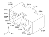
図39及び図40を参照すると、可動部材50Aは、絶縁体からなる本体部材510Aと、金属からなる2つのロック部材560Aと、金属からなる2つのカバー部材580Aとを備えている。可動部材50Aは、X方向と平行な軸に対して180度回転対称な形状を有している。   39 and 40, the movable member 50A includes a main body member 510A made of an insulator, two lock members 560A made of metal, and two cover members 580A made of metal. The movable member 50A has a 180-degree rotationally symmetric shape with respect to an axis parallel to the X direction.

図39を参照すると、本体部材510Aは、上部512Aと、下部514Aと、2つの側部516Aと、中空部518Aとを有している。中空部518Aは、上部512A,下部514A及び側部516Aによって囲まれた空間であり、前方及び後方に開口している。側部516Aの夫々には、ガイド溝550Aが形成されている。ガイド溝550Aは、中空部518AのY方向両側に夫々位置しており、且つ、前方及び後方に開口している。ガイド溝550Aを上下に囲む内壁には、圧入溝522Aが形成されている。圧入溝522Aは、後方に開口している。   Referring to FIG. 39, the main body member 510A has an upper part 512A, a lower part 514A, two side parts 516A, and a hollow part 518A. The hollow portion 518A is a space surrounded by the upper portion 512A, the lower portion 514A, and the side portion 516A, and opens forward and rearward. A guide groove 550A is formed in each of the side portions 516A. The guide grooves 550A are located on both sides in the Y direction of the hollow portion 518A, and open forward and rearward. A press-fit groove 522A is formed on the inner wall that surrounds the guide groove 550A vertically. The press-fitting groove 522A opens rearward.

可動部材50Aは、4つの前進力受部532Aと、2つの後退力受部534Aと、4つの前進被規制部540Aとを備えている。前進力受部532Aのうちの2つは、上部512Aの後端面から前方に凹んだ2つの凹みの前端面であり、前進力受部532Aのうちの他の2つは、下部514Aの後端面から前方に凹んだ2つの凹みの前端面である。後退力受部534Aの一方は、上部512Aの前端面から後方に凹んだ凹みの後端面であり、後退力受部534Aの他方は、下部514Aの前端面から後方に凹んだ凹みの後端面である。前進被規制部540Aのうちの2つは、上部512Aの前端面の一部であり、上部512Aの後退力受部534AのY方向両側に夫々位置している。前進被規制部540Aのうちの他の2つは、下部514Aの前端面の一部であり、下部514Aの後退力受部534AのY方向両側に夫々位置している。   The movable member 50A includes four forward force receiving portions 532A, two backward force receiving portions 534A, and four forward restricted portions 540A. Two of the advancing force receiving portions 532A are front end surfaces of two recesses recessed forward from the rear end surface of the upper portion 512A, and the other two of the advancing force receiving portions 532A are rear end surfaces of the lower portion 514A. It is a front-end surface of two dents dented ahead from. One of the retracting force receiving portions 534A is a rear end surface of a recess recessed backward from the front end surface of the upper portion 512A, and the other of the retracting force receiving portions 534A is a rear end surface of a recess recessed rearward from the front end surface of the lower portion 514A. is there. Two of the forward restricted parts 540A are a part of the front end surface of the upper part 512A, and are respectively located on both sides in the Y direction of the backward force receiving part 534A of the upper part 512A. The other two of the forward restricted parts 540A are a part of the front end surface of the lower part 514A, and are respectively located on both sides in the Y direction of the backward force receiving part 534A of the lower part 514A.

図40を参照すると、ロック部材560Aの夫々は、曲げを有する一枚板である。2つのロック部材560Aは、互いに同一な形状を有している。但し、ロック部材560Aの一方は、ロック部材560Aの他方に対して、X方向と平行な軸を中心にして180°回転した状態に配置されている。   Referring to FIG. 40, each of the lock members 560A is a single plate having a bend. The two lock members 560A have the same shape. However, one of the lock members 560A is arranged in a state rotated by 180 ° around the axis parallel to the X direction with respect to the other of the lock members 560A.

ロック部材560Aの夫々は、圧入部562Aと、支持部564Aと、被操作部566Aと、ロック部568Aとを有している。圧入部562Aは、ロック部材560Aの後端に位置している。支持部564Aは、圧入部562Aから前方に長く延びており、XY平面において弾性変形可能である。被操作部566Aは、ロック部材560Aに形成された湾曲部である。ロック部568Aは、X方向と交差する方向に延びるロック爪であり、支持部564Aの前端に設けられている。   Each of the lock members 560A has a press-fit portion 562A, a support portion 564A, an operated portion 566A, and a lock portion 568A. The press-fit portion 562A is located at the rear end of the lock member 560A. The support portion 564A extends forward from the press-fit portion 562A and can be elastically deformed in the XY plane. The operated portion 566A is a curved portion formed on the lock member 560A. The lock portion 568A is a lock claw that extends in a direction crossing the X direction, and is provided at the front end of the support portion 564A.

カバー部材580Aの夫々は、曲げを有する一枚板である。2つのカバー部材580Aは、互いに同一な形状を有している。また、2つのカバー部材580Aは、XZ平面に対して鏡対称に配置されている。カバー部材580Aの夫々は、圧入部582Aと、カバー584Aを有している。また、カバー部材580Aには、受容部586Aが形成されている。圧入部582Aは、カバー部材580Aの後端に位置している。カバー584Aは、圧入部582Aから前方に延びている。受容部586Aは、カバー584Aに囲まれた空間であり、Y方向内側及び後方に開口している。   Each of the cover members 580A is a single plate having a bend. The two cover members 580A have the same shape. Further, the two cover members 580A are arranged in mirror symmetry with respect to the XZ plane. Each of the cover members 580A has a press-fit portion 582A and a cover 584A. The cover member 580A has a receiving portion 586A. The press-fit portion 582A is located at the rear end of the cover member 580A. The cover 584A extends forward from the press-fit portion 582A. The receiving portion 586A is a space surrounded by the cover 584A and opens inward and rearward in the Y direction.

図39及び図40を参照すると、ロック部材560Aは、後方から本体部材510Aに取り付けられており、圧入溝522Aによって夫々保持されている。カバー部材580Aは、前方から本体部材510Aに取り付けられており、本体部材510Aの側部516Aによって夫々保持されている。支持部564A及びカバー584Aは、本体部材510Aの前端から前方に突出している。   Referring to FIGS. 39 and 40, the lock member 560A is attached to the main body member 510A from the rear, and is held by the press-fit grooves 522A. The cover member 580A is attached to the main body member 510A from the front, and is held by the side portions 516A of the main body member 510A. The support portion 564A and the cover 584A protrude forward from the front end of the main body member 510A.

図53を参照すると、支持部564Aの殆どは、受容部586A内に受容されており、受容部586A内において弾性変形が許容されている。ロック部568Aは、支持部564Aに支持されており、Y方向に移動可能である。支持部564Aが弾性変形していないバネの初期状態において、被操作部566Aの一部は、受容部586AからY方向内側に突出している。また、バネの初期状態において、ロック部568Aの先端部は、受容部586AからY方向内側に突出している。   Referring to FIG. 53, most of the support portion 564A is received in the receiving portion 586A, and elastic deformation is allowed in the receiving portion 586A. The lock portion 568A is supported by the support portion 564A, and is movable in the Y direction. In the initial state of the spring in which the support portion 564A is not elastically deformed, a part of the operated portion 566A protrudes inward in the Y direction from the receiving portion 586A. In the initial state of the spring, the distal end portion of the lock portion 568A protrudes inward in the Y direction from the receiving portion 586A.

図41を参照すると、操作部材60Aは、X方向と平行な軸に対して180度回転対称な形状を有している。詳しくは、操作部材60Aは、上部602Aと、下部604Aと、2つの側部606Aと、中空部608Aとを有している。中空部608Aは、上部602A,下部604A及び側部606Aによって囲まれた空間であり、前方及び後方に開口している。図41、図51及び図52を参照すると、上部602A及び下部604Aの夫々には、操作部610Aが設けられている。   Referring to FIG. 41, the operation member 60A has a 180-degree rotationally symmetric shape with respect to an axis parallel to the X direction. Specifically, the operation member 60A has an upper part 602A, a lower part 604A, two side parts 606A, and a hollow part 608A. The hollow portion 608A is a space surrounded by the upper portion 602A, the lower portion 604A, and the side portion 606A, and opens forward and rearward. 41, 51, and 52, an operation unit 610A is provided in each of the upper part 602A and the lower part 604A.

図41及び図42を参照すると、操作部材60Aは、4つの前進力付加部622Aと、2つの後退力付加部624Aと、2つの前進操作被規制部632Aと、1つの後退操作被規制部634Aと、4つの操作突部640Aと、2つのガイド溝650Aとを備えている。前進力付加部622A、後退力付加部624A、操作突部640A及びガイド溝650Aは、中空部608A内に設けられている。   Referring to FIGS. 41 and 42, the operation member 60A includes four forward force adding portions 622A, two backward force adding portions 624A, two forward operation restricted portions 632A, and one backward operation restricted portion 634A. And four operation protrusions 640A and two guide grooves 650A. The forward force adding portion 622A, the backward force adding portion 624A, the operation protrusion 640A, and the guide groove 650A are provided in the hollow portion 608A.

前進力付加部622Aのうちの2つは、中空部608A内において上部602Aの後端近傍から下方に突出した2つの突起の前端面であり、前進力付加部622Aのうちの他の2つは、中空部608A内において下部604Aの後端近傍から上方に突出した2つの突起の前端面である。後退力付加部624Aの一方は、中空部608A内において上部602Aの前端近傍から下方に突出した突起の後端面であり、後退力付加部624Aの他方は、中空部608A内において下部604Aの前端近傍から上方に突出した突起の後端面である。 Two of the forward force addition portions 622A are front end surfaces of two protrusions that protrude downward from the vicinity of the rear end of the upper portion 602A in the hollow portion 608A, and the other two of the forward force addition portions 622A are These are front end surfaces of two protrusions protruding upward from the vicinity of the rear end of the lower portion 604A in the hollow portion 608A. One of the receding force adding portions 624A is a rear end surface of a protrusion protruding downward from the vicinity of the front end of the upper portion 602A in the hollow portion 608A, and the other of the receding force adding portions 624A is the front end of the lower portion 604A in the hollow portion 608A. It is a rear end surface of the protrusion protruding upward from the vicinity.

操作突部640Aのうちの2つは、+Y側の側部606Aに対応しており、操作突部640Aのうちの他の2つは、−Y側の側部606Aに対応している。詳しくは、+Y側の2つの操作突部640Aは、+Y側の側部606AからY方向内側に離れて+Y側の側部606AとY方向において対向している。同様に、−Y側の2つの操作突部640Aは、−Y側の側部606AとY方向において対向している。側部606Aの夫々に対応する2つの操作突部640Aにおいて、操作突部640Aの一方は、下方に突出しつつ後方に延びており、操作突部640Aの他方は、上方に突出しつつ後方に延びている。   Two of the operation protrusions 640A correspond to the + Y side part 606A, and the other two of the operation protrusions 640A correspond to the −Y side part 606A. Specifically, the two + Y side operation protrusions 640A are separated from the + Y side portion 606A inward in the Y direction and face the + Y side portion 606A in the Y direction. Similarly, the two operation protrusions 640A on the −Y side face the side part 606A on the −Y side in the Y direction. In the two operation protrusions 640A corresponding to the respective side portions 606A, one of the operation protrusions 640A extends backward while protruding downward, and the other of the operation protrusions 640A extends backward while protruding upward. Yes.

図49を参照すると、XY平面において、操作突部640Aは、Y方向外側に突出している。図41及び図42を参照すると、操作突部640Aの夫々のY方向外側の面は、傾斜面642Aと、外側面644Aとから構成されている。傾斜面642Aは、X方向と斜交する面であり、操作突部640Aの後部に設けられている。外側面644Aは、XZ平面と平行な面であり、操作突部640Aの前部に設けられている。ガイド溝650Aの一方は、+Y側の2つの操作突部640Aと+Y側の側部606Aとの間に形成された溝であり、ガイド溝650Aの他方は、−Y側の2つの操作突部640Aと−Y側の側部606Aとの間に形成された溝である。ガイド溝650Aは、中空部608AのY方向外側に位置しており、且つ、前方及び後方に開口している。   Referring to FIG. 49, on the XY plane, the operation protrusion 640A protrudes outward in the Y direction. Referring to FIGS. 41 and 42, the outer surface in the Y direction of each of the operation protrusions 640A includes an inclined surface 642A and an outer surface 644A. The inclined surface 642A is a surface oblique to the X direction, and is provided at the rear portion of the operation protrusion 640A. The outer side surface 644A is a surface parallel to the XZ plane, and is provided at the front portion of the operation protrusion 640A. One of the guide grooves 650A is a groove formed between the two + Y side operation protrusions 640A and the + Y side side 606A, and the other of the guide grooves 650A is the two operation protrusions on the −Y side. This is a groove formed between 640A and the −Y side portion 606A. The guide groove 650A is located on the outer side in the Y direction of the hollow portion 608A, and opens forward and rearward.

前進操作被規制部632Aの一方は、上部602Aの前端面から後方に凹んだ凹みの後端面であり、前進操作被規制部632Aの他方は、下部604Aの前端面から後方に凹んだ凹みの後端面である。後退操作被規制部634Aは、操作部材60Aの後端面であり、上部602Aの後端面,下部604Aの後端面及び側部606Aの後端面を含んでいる。   One of the forward operation restricted portions 632A is a rear end surface of a recess recessed backward from the front end surface of the upper portion 602A, and the other of the forward operation restricted portions 632A is behind a recess recessed backward from the front end surface of the lower portion 604A. It is an end face. The backward operation restricted portion 634A is a rear end surface of the operation member 60A, and includes a rear end surface of the upper portion 602A, a rear end surface of the lower portion 604A, and a rear end surface of the side portion 606A.

図33、図34及び図45を参照すると、コネクタ10Aは、上述した主部材20A,可動部材50A及び操作部材60Aからなる組立体である。コネクタ10Aを組み立てる際、まず、可動部材50Aを、後方から操作部材60Aの中空部608Aに挿入し、前進力受部532Aを、前進力付加部622Aの前方に配置する。これにより、2つのカバー部材580Aは、2つのガイド溝650Aを夫々通過して、操作部材60Aの前端から前方に突出する。次に、コネクタ本体30Aを収容した主部材20Aを、後方から可動部材50Aの中空部518Aに挿入し、前進操作規制部414Aを、前進操作被規制部632Aの前方に配置すると共に、前進規制部430Aを、前進被規制部540Aの前方に配置する。これにより、2つの突出部420Aは、可動部材50Aのガイド溝550Aに夫々受容される。嵌合部310を含む主部材20Aの前部は、操作部材60Aの前端から前方に突出する。このとき、コネクタ本体30Aの嵌合部310は、Y方向において、2つのロック部568Aの間に位置している。   Referring to FIGS. 33, 34 and 45, the connector 10A is an assembly including the main member 20A, the movable member 50A and the operation member 60A described above. When assembling the connector 10A, first, the movable member 50A is inserted into the hollow portion 608A of the operation member 60A from the rear, and the advance force receiving portion 532A is disposed in front of the advance force adding portion 622A. Thus, the two cover members 580A pass through the two guide grooves 650A and project forward from the front end of the operation member 60A. Next, the main member 20A containing the connector main body 30A is inserted into the hollow portion 518A of the movable member 50A from the rear, the forward operation restricting portion 414A is disposed in front of the forward operation restricted portion 632A, and the forward restricting portion. 430A is disposed in front of the forward restricted portion 540A. Thereby, the two protrusions 420A are received in the guide grooves 550A of the movable member 50A, respectively. The front part of the main member 20A including the fitting part 310 protrudes forward from the front end of the operation member 60A. At this time, the fitting portion 310 of the connector main body 30A is located between the two lock portions 568A in the Y direction.

コネクタ10Aは、上述のように組み立てられたとき、図33及び図43乃至図46に示される初期状態にある。図43乃至図46を参照すると、コネクタ10Aが初期状態にあるとき、操作部材60Aは、YZ平面において可動部材50A及び主部材20Aを部分的に囲んでいる。詳しくは、可動部材50Aの本体部材510A全体と、主部材20AのX方向における中間部は、操作部材60Aの中空部608Aの内部に収容されている。本実施の形態においても、操作部610AにX方向に沿った力を加えることで、操作部材60Aを移動操作できる。図51及び図52を参照すると、操作者は、2つの操作部610Aを上下に挟むことで、操作部材60Aをワンハンド操作できる。   When the connector 10A is assembled as described above, it is in the initial state shown in FIGS. 43 to 46, when the connector 10A is in the initial state, the operation member 60A partially surrounds the movable member 50A and the main member 20A in the YZ plane. Specifically, the entire main body member 510A of the movable member 50A and the intermediate portion in the X direction of the main member 20A are accommodated in the hollow portion 608A of the operation member 60A. Also in the present embodiment, the operation member 60A can be moved and operated by applying a force along the X direction to the operation unit 610A. Referring to FIGS. 51 and 52, the operator can operate the operation member 60A in one hand by sandwiching the two operation units 610A up and down.

図43乃至図45を参照すると、初期状態において、操作部材60Aの後退操作被規制部634Aは、主部材20Aの後退操作規制部416Aの直前に位置している。このため、操作部材60A(後退操作被規制部634A)は、後方に移動できない。一方、操作部材60Aの前進操作被規制部632Aは、主部材20Aの前進操作規制部414Aから移動距離D2だけ離れて後方に位置している。このため、操作部材60A(前進操作被規制部632A)は、第1の実施の形態と同様に、移動距離D2だけ前方に移動できる。また、移動距離D2だけ前方に移動した前進操作被規制部632Aは、移動距離D2だけ後方に移動できる。   43 to 45, in the initial state, the retracting operation restricted portion 634A of the operating member 60A is positioned immediately before the retracting operation restricting portion 416A of the main member 20A. For this reason, the operation member 60A (reverse operation restricted portion 634A) cannot move backward. On the other hand, the forward operation restricted portion 632A of the operation member 60A is located rearward from the forward operation restricting portion 414A of the main member 20A by a movement distance D2. For this reason, the operation member 60A (the forward operation restricted portion 632A) can move forward by the movement distance D2 as in the first embodiment. Further, the forward operation restricted portion 632A that has moved forward by the moving distance D2 can move backward by the moving distance D2.

以上の説明から理解されるように、前進操作被規制部632Aは、X方向における所定の操作移動範囲R2の前端位置PFOと後端位置PROとの間を、主部材20Aに対して相対的に、移動距離D2だけ前後に移動可能である。前端位置PFOは、主部材20Aの前進操作規制部414AのX方向における位置であり、後端位置PROは、後退操作被規制部634Aが主部材20Aの後退操作規制部416Aと接触しているときの、前進操作被規制部632AのX方向における位置である。   As can be understood from the above description, the forward operation restricted portion 632A is relatively relative to the main member 20A between the front end position PFO and the rear end position PRO of the predetermined operation movement range R2 in the X direction. It is possible to move back and forth by the moving distance D2. The front end position PFO is a position in the X direction of the forward operation restricting portion 414A of the main member 20A, and the rear end position PRO is when the reverse operation restricted portion 634A is in contact with the reverse operation restricting portion 416A of the main member 20A. Of the forward operation restricted portion 632A in the X direction.

前進操作被規制部632Aは、操作部材60Aの一部である。以下、第1の実施の形態と同じく、前進操作被規制部632Aの位置を、操作部材60Aの位置として説明する。即ち、操作部材60Aは、X方向における操作移動範囲R2の前端位置PFOと後端位置PROとの間を、主部材20Aに対して相対的に、前後に移動距離D2だけ移動可能である。前進操作規制部414Aは、操作部材60Aの前方への移動を規制して、操作移動範囲R2の前端位置PFOを規定している。また、後退操作規制部416Aは、操作部材60Aの後方への移動を規制して、操作移動範囲R2の後端位置PROを規定している。   The forward operation restricted portion 632A is a part of the operation member 60A. Hereinafter, as in the first embodiment, the position of the forward operation restricted portion 632A will be described as the position of the operation member 60A. That is, the operation member 60A can move back and forth by a movement distance D2 relative to the main member 20A between the front end position PFO and the rear end position PRO of the operation movement range R2 in the X direction. The forward operation restricting portion 414A restricts the forward movement of the operation member 60A and defines the front end position PFO of the operation movement range R2. Further, the backward operation restricting portion 416A restricts the backward movement of the operation member 60A and defines the rear end position PRO of the operation movement range R2.

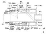
図45を参照すると、初期状態において、可動部材50Aの前進被規制部540Aは、主部材20Aの前進規制部430Aから後方に移動距離D1だけ離れた後端位置PRに位置している。このため、可動部材50A(前進被規制部540A)は、移動距離D1だけ前方に移動できる。また、移動距離D1だけ前方に移動した前進被規制部540Aは、移動距離D1だけ後方に移動できる。加えて、初期状態において、可動部材50Aの後端(前進力受部532A)は、操作部材60Aの前進力付加部622Aから所定距離D3だけ離れて前方に位置している。このため、可動部材50A(前進被規制部540A)は、所定距離D3だけ後方に移動できる。また、所定距離D3だけ後方に移動した前進被規制部540Aは、所定距離D3だけ前方に移動できる。   Referring to FIG. 45, in the initial state, the forward restricted portion 540A of the movable member 50A is located at the rear end position PR separated from the forward restricting portion 430A of the main member 20A by the movement distance D1. For this reason, the movable member 50A (the forward restricted portion 540A) can move forward by the moving distance D1. Further, the forward restricted portion 540A that has moved forward by the moving distance D1 can move backward by the moving distance D1. In addition, in the initial state, the rear end (advance force receiving portion 532A) of the movable member 50A is positioned forward by a predetermined distance D3 from the advance force addition portion 622A of the operation member 60A. For this reason, the movable member 50A (advanced regulated portion 540A) can move backward by a predetermined distance D3. Further, the forward restricted portion 540A that has moved backward by the predetermined distance D3 can move forward by the predetermined distance D3.

以上の説明から理解されるように、前進被規制部540Aは、X方向における移動範囲R1の前端位置PFと後端位置PRとの間を、主部材20Aに対して相対的に、移動距離D1だけ前後に移動可能である。前端位置PFは、主部材20Aの前進規制部430AのX方向における位置であり、後端位置PRは、操作部材60Aの後退操作被規制部634Aが主部材20Aの後退操作規制部416Aと接触しており且つ前進力受部532Aが前進力付加部622Aから前方に所定距離D3だけ離れているときの、前進被規制部540AのX方向における位置である。   As can be understood from the above description, the forward restricted portion 540A moves between the front end position PF and the rear end position PR of the movement range R1 in the X direction relative to the main member 20A. Can only move back and forth. The front end position PF is a position in the X direction of the forward restricting portion 430A of the main member 20A, and the rear end position PR is the backward operation restricted portion 634A of the operating member 60A in contact with the reverse operation restricting portion 416A of the main member 20A. This is the position in the X direction of the forward restricted portion 540A when the forward force receiving portion 532A is separated from the forward force adding portion 622A by a predetermined distance D3.

前進被規制部540Aは、可動部材50Aの一部である。以下、第1の実施の形態と同じく、前進被規制部540Aの位置を、可動部材50Aの位置として説明する。即ち、可動部材50Aは、X方向における移動範囲R1の前端位置PFと後端位置PRとの間を、主部材20Aに対して相対的に、前後に移動距離D1だけ移動可能である。前進規制部430Aは、第1の実施の形態と同様に、可動部材50Aの前方への移動を規制して、移動範囲R1の前端位置PFを規定している。一方、第1の実施の形態と異なり、主部材20Aは、可動部材50Aの後方への移動を直接的に規制する部位を備えていない。移動範囲R1の後端位置PRは、後端位置PROに位置したときの操作部材60Aの前進力付加部622Aによって規定されている。   The forward restricted portion 540A is a part of the movable member 50A. Hereinafter, as in the first embodiment, the position of the forward restricted portion 540A will be described as the position of the movable member 50A. That is, the movable member 50A is movable back and forth by a movement distance D1 relative to the main member 20A between the front end position PF and the rear end position PR of the movement range R1 in the X direction. Similarly to the first embodiment, the forward restricting portion 430A restricts the forward movement of the movable member 50A and defines the front end position PF of the movement range R1. On the other hand, unlike the first embodiment, the main member 20A does not include a portion that directly regulates the backward movement of the movable member 50A. The rear end position PR of the movement range R1 is defined by the forward force adding portion 622A of the operation member 60A when it is located at the rear end position PRO.

図1及び図33を参照すると、上述した初期状態にあるコネクタ10A全体を相手側コネクタ80に向かって移動させると、コネクタ10Aは、その初期状態を維持したまま、相手側コネクタ80と嵌合した嵌合状態になる。以下、コネクタ10Aと相手側コネクタ80との嵌合状態をロックするための操作及び嵌合状態のロックを解除するための操作について、第1の実施の形態との相違点を中心に説明する。   1 and 33, when the entire connector 10A in the initial state described above is moved toward the mating connector 80, the connector 10A is fitted with the mating connector 80 while maintaining the initial state. It will be in a fitting state. Hereinafter, an operation for locking the fitting state between the connector 10A and the mating connector 80 and an operation for releasing the locking of the fitting state will be described with a focus on differences from the first embodiment.

図45を参照すると、初期状態において、操作部材60Aの前進力付加部622Aは、第1の実施の形態と同様に、可動部材50Aの前進力受部532Aから後方に所定距離D3だけ離れてX方向において前進力受部532Aと対向している。所定距離D3は、移動距離D2よりも小さい。このため、操作部材60Aを操作移動範囲R2の後端位置PROから前方に所定距離D3だけ移動すると、前進力付加部622Aは、前進力受部532Aと接触する。前進力付加部622Aが前進力受部532Aと接触したとき、コネクタ10Aは、図47に示される中間状態にある。   Referring to FIG. 45, in the initial state, the advancing force adding portion 622A of the operating member 60A is spaced apart from the advancing force receiving portion 532A of the movable member 50A by a predetermined distance D3, as in the first embodiment. It faces the forward force receiving portion 532A in the direction. The predetermined distance D3 is smaller than the movement distance D2. For this reason, when the operation member 60A is moved forward from the rear end position PRO of the operation movement range R2 by a predetermined distance D3, the forward force adding portion 622A comes into contact with the forward force receiving portion 532A. When the forward force adding portion 622A comes into contact with the forward force receiving portion 532A, the connector 10A is in an intermediate state shown in FIG.

図44及び図46を参照すると、主部材20Aの維持部422Aは、その前端部424Aを除き、操作部材60Aの操作突部640Aを越えてY方向外側に位置している。また、初期状態において、維持部422Aの後端は、所定距離D3を大きく越えて可動部材50Aの被操作部566Aの後方に位置している。このため、可動部材50Aの支持部564Aは、Y方向外側に弾性変形している。詳しくは、被操作部566Aは、維持部422AのY方向外側に位置しており、操作突部640AからY方向外側に離れている。従って、操作部材60Aが後端位置PROから前方に所定距離D3だけ移動する間、操作部材60Aは、被操作部566Aに力を加えない。   44 and 46, the maintenance portion 422A of the main member 20A is located outside the operation protrusion 640A of the operation member 60A outside the Y direction except for the front end portion 424A. Further, in the initial state, the rear end of the maintaining portion 422A is positioned behind the operated portion 566A of the movable member 50A so as to greatly exceed the predetermined distance D3. For this reason, the support portion 564A of the movable member 50A is elastically deformed outward in the Y direction. Specifically, the operated portion 566A is located on the outer side in the Y direction of the maintaining portion 422A, and is separated from the operating protrusion 640A on the outer side in the Y direction. Therefore, the operation member 60A does not apply force to the operated portion 566A while the operation member 60A moves forward from the rear end position PRO by the predetermined distance D3.

以上の説明から理解されるように、本実施の形態による維持部422Aには、第1の実施の形態と同様な仮保持部450Aが設けられている。仮保持部450Aは、操作部材60Aの操作突部640Aを越えてY方向外側に位置している。操作部材60Aが操作移動範囲R2の後端位置PROに位置しているとき、被操作部566Aは、Y方向において仮保持部450Aの外側に位置している。図44及び図45を参照すると、仮保持部450Aの仮保持により、操作部材60Aが後端位置PROから前方に所定距離D3だけ移動する間、可動部材50Aは、後端位置PRに維持される。従って、操作部材60Aは、可動部材50Aに対して相対的に、X方向において所定距離D3だけ前方に移動可能である。   As can be understood from the above description, the maintenance unit 422A according to the present embodiment is provided with a temporary holding unit 450A similar to that of the first embodiment. The temporary holding portion 450A is located on the outer side in the Y direction beyond the operation protrusion 640A of the operation member 60A. When the operation member 60A is located at the rear end position PRO of the operation movement range R2, the operated portion 566A is located outside the temporary holding portion 450A in the Y direction. 44 and 45, the temporary holding of the temporary holding portion 450A causes the movable member 50A to be maintained at the rear end position PR while the operation member 60A moves forward from the rear end position PRO by a predetermined distance D3. . Therefore, the operation member 60A can move forward by a predetermined distance D3 in the X direction relative to the movable member 50A.

図45を参照すると、後端位置PROから所定距離D3だけ前方に位置した操作部材60A(図47参照)を更に前方に移動すると、前進力付加部622Aは、前進力受部532Aに前方に向かう前進力を付加する。可動部材50Aは、前進力により、操作部材60Aと共に前方に移動する。図48及び図50を参照すると、操作部材60Aを前方に移動し続けると、操作部材60Aの前進操作被規制部632Aが主部材20Aの前進操作規制部414Aに突き当たり、操作部材60Aは主部材20Aに対して停止する。前進操作被規制部632Aが前進操作規制部414Aに突き当たったとき、コネクタ10Aは、図48乃至図54に示されるロック状態にある。   Referring to FIG. 45, when the operation member 60A (see FIG. 47) positioned forward by a predetermined distance D3 from the rear end position PRO is further moved forward, the forward force adding portion 622A moves forward toward the forward force receiving portion 532A. Add forward force. The movable member 50A moves forward together with the operation member 60A by a forward force. 48 and 50, when the operation member 60A continues to move forward, the forward operation restricted portion 632A of the operation member 60A hits the forward operation restriction portion 414A of the main member 20A, and the operation member 60A is the main member 20A. Stop against. When the forward operation restricted portion 632A hits the forward operation restricting portion 414A, the connector 10A is in the locked state shown in FIGS.

図54を参照すると、ロック状態において、操作部材60Aは、操作移動範囲R2の前端位置PFOに位置する。図49及び図54を参照すると、このとき可動部材50Aは、移動範囲R1の前端位置PFに位置し、可動部材50Aの前進被規制部540Aは、主部材20Aの前進規制部430Aの直後に位置する。第1の実施の形態と同様、可動部材50Aは、前端位置PFを越えて前方に移動することができない。   Referring to FIG. 54, in the locked state, the operation member 60A is located at the front end position PFO of the operation movement range R2. 49 and 54, at this time, the movable member 50A is positioned at the front end position PF of the movement range R1, and the forward restricted portion 540A of the movable member 50A is located immediately after the forward restricting portion 430A of the main member 20A. To do. Similar to the first embodiment, the movable member 50A cannot move forward beyond the front end position PF.

図53を参照すると、ロック状態において、可動部材50Aの被操作部566Aは、主部材20Aの維持部422Aの前方に位置しており、維持部422Aと接触していない。また、被操作部566Aは、操作突部640Aの外側面644Aの後方に位置しており、操作突部640Aと接触していない。このため、被操作部566Aは、Y方向外側に向かう力を受けず、弾性変形していた支持部564Aは、バネの初期状態に復帰する。この結果、図48、図49、図50、図52及び図53に示されるように、ロック部568Aは、カバー584Aの受容部586AからY方向内側に突出する。   Referring to FIG. 53, in the locked state, the operated portion 566A of the movable member 50A is located in front of the maintaining portion 422A of the main member 20A and is not in contact with the maintaining portion 422A. The operated portion 566A is located behind the outer surface 644A of the operation protrusion 640A and does not contact the operation protrusion 640A. For this reason, the operated portion 566A does not receive a force toward the outside in the Y direction, and the support portion 564A that has been elastically deformed returns to the initial state of the spring. As a result, as shown in FIGS. 48, 49, 50, 52, and 53, the lock portion 568A protrudes inward in the Y direction from the receiving portion 586A of the cover 584A.

図53を参照すると、カバー584Aから突出したロック部568Aの先端部は、嵌合状態にある相手側コネクタ80の相手側ロック部824の内部に位置する。図53及び図54を参照すると、第1の実施の形態と同様に、嵌合状態において操作部材60Aが操作移動範囲R2の前端位置PFOに位置し且つ可動部材50Aが移動範囲R1の前端位置PFに位置しているとき、ロック部568Aは、相手側ロック部824と共に嵌合状態をロックしている。これにより、コネクタ10Aの、相手側コネクタ80からの抜去が防止される。   Referring to FIG. 53, the distal end portion of the lock portion 568A protruding from the cover 584A is located inside the mating lock portion 824 of the mating connector 80 in the fitted state. 53 and 54, similarly to the first embodiment, the operating member 60A is positioned at the front end position PFO of the operation movement range R2 and the movable member 50A is the front end position PF of the movement range R1 in the fitted state. The locking portion 568A locks the fitting state together with the counterpart locking portion 824. This prevents the connector 10A from being removed from the mating connector 80.

図54を参照すると、ロック状態において、操作部材60Aの後退力付加部624Aは、可動部材50Aの後退力受部534Aから前方に所定距離D3だけ離れてX方向において後退力受部534Aと対向している。このため、操作部材60Aを操作移動範囲R2の前端位置PFOから後方に所定距離D3だけ移動すると、後退力付加部624Aは、後退力受部534Aと接触する。後退力付加部624Aが後退力受部534Aと接触したとき、コネクタ10Aは、図55乃至図58に示されるアンロック状態にある。   Referring to FIG. 54, in the locked state, the retracting force adding portion 624A of the operation member 60A is separated from the retracting force receiving portion 534A of the movable member 50A by a predetermined distance D3 and faces the retracting force receiving portion 534A in the X direction. ing. For this reason, when the operation member 60A is moved rearward from the front end position PFO of the operation movement range R2 by the predetermined distance D3, the retraction force adding unit 624A comes into contact with the retraction force receiving unit 534A. When the retracting force adding portion 624A comes into contact with the retracting force receiving portion 534A, the connector 10A is in the unlocked state shown in FIGS.

図54を参照すると、操作部材60Aが操作移動範囲R2の前端位置PFOから後方に所定距離D3だけ移動する間、可動部材50Aは、移動範囲R1の前端位置PFに維持される。換言すれば、操作部材60Aは、可動部材50Aに対して相対的に、X方向において所定距離D3だけ後方に移動可能である。   Referring to FIG. 54, the movable member 50A is maintained at the front end position PF of the movement range R1 while the operation member 60A moves rearward from the front end position PFO of the operation movement range R2 by a predetermined distance D3. In other words, the operation member 60A can move backward by the predetermined distance D3 in the X direction relative to the movable member 50A.

図53、図54及び図57を参照すると、操作部材60Aが前端位置PFOから後方に所定距離D3だけ移動する間、操作部材60Aの操作突部640Aの傾斜面642Aが可動部材50Aの被操作部566Aに接触し、被操作部566AをY方向外側に押圧する。これにより、支持部564Aは、Y方向外側に弾性変形し、ロック部568Aは、Y方向外側に移動する。操作部材60Aが、前端位置PFOから後方に所定距離D3だけ離れた位置にあるとき、被操作部566Aは、操作突部640Aの外側面644A上に位置する。   53, 54 and 57, while the operation member 60A moves rearward from the front end position PFO by a predetermined distance D3, the inclined surface 642A of the operation protrusion 640A of the operation member 60A is the operated portion of the movable member 50A. 566A is touched, and the operated portion 566A is pressed outward in the Y direction. Thereby, the support portion 564A is elastically deformed outward in the Y direction, and the lock portion 568A moves outward in the Y direction. When the operation member 60A is at a position away from the front end position PFO by a predetermined distance D3, the operated portion 566A is located on the outer surface 644A of the operation protrusion 640A.

換言すれば、嵌合状態において操作部材60Aが操作移動範囲R2の前端位置PFOから所定距離D3だけ後方に位置し且つ可動部材50Aが移動範囲R1の前端位置PFに位置しているとき、被操作部566Aは、Y方向において操作突部640Aの外側に位置している。この結果、ロック部568Aは、Y方向において相手側ロック部824の外側に移動して嵌合状態のロックを解除している。図55、図56及び図57を参照すると、嵌合状態のロックが解除されたとき、ロック部568Aは、カバー584A内に受容される。 In other words, when the operating member 60A is located behind the front end position PFO of the operation movement range R2 by the predetermined distance D3 and the movable member 50A is located at the front end position PF of the movement range R1 in the fitted state, The portion 566A is located outside the operation protrusion 640A in the Y direction. As a result, the lock portion 568A moves to the outside of the counterpart lock portion 824 in the Y direction to release the lock in the fitted state. Referring to FIGS. 55, 56 and 57, when the lock in the fitted state is released, the lock portion 568A is received in the cover 584A.

図58を参照すると、前端位置PFOから所定距離D3だけ後方に位置した操作部材60Aを更に後方に移動すると、後退力付加部624Aは、後退力受部534Aに後方に向かう後退力を付加する。可動部材50Aは、後退力により、操作部材60Aと共に後方に移動する。   Referring to FIG. 58, when the operation member 60A located rearward by the predetermined distance D3 from the front end position PFO is further moved rearward, the retreating force adding unit 624A applies a retreating force directed rearward to the retreating force receiving unit 534A. The movable member 50A moves backward together with the operation member 60A due to the retreating force.

図54に示された操作部材60Aは、操作移動範囲R2の前端位置PFOに位置しており、図57に示された操作部材60Aは、操作移動範囲R2の前端位置PFOから所定距離D3だけ後方に位置している。図54及び図57から理解されるように、操作部材60Aが操作移動範囲R2の前端位置PFOから所定距離D3を所定付加距離D4だけ超えて後方に位置し且つ可動部材50Aが移動範囲R1の前端位置PFから所定付加距離D4だけ後方に位置しているとき、被操作部566Aは、第1の実施の形態と同様に、Y方向において維持部422Aの外側に位置し、ロック部568AのY方向外側に移動した状態が維持されている状態となる。   The operation member 60A shown in FIG. 54 is located at the front end position PFO of the operation movement range R2, and the operation member 60A shown in FIG. 57 is rearward from the front end position PFO of the operation movement range R2 by a predetermined distance D3. Is located. As understood from FIGS. 54 and 57, the operating member 60A is positioned rearward from the front end position PFO of the operation moving range R2 by exceeding the predetermined distance D3 by the predetermined additional distance D4, and the movable member 50A is positioned at the front end of the moving range R1. When it is located behind the position PF by a predetermined additional distance D4, the operated portion 566A is located outside the maintaining portion 422A in the Y direction and the Y direction of the lock portion 568A, as in the first embodiment. The state moved to the outside is maintained.

図56乃至図58を図43乃至図45と併せて参照すると、操作部材60Aを後方に移動し続けると、操作部材60Aの後退操作被規制部634Aが主部材20Aの後退操作規制部416Aと接触し、操作部材60Aは、操作移動範囲R2の後端位置PROに位置する。図45を参照すると、本実施の形態によれば、操作部材60Aが操作移動範囲R2の後端位置PROに位置したとき、可動部材50Aは、移動範囲R1の後端位置PRに位置する。このとき、コネクタ10Aは、図33及び図43乃至図46に示される初期状態にある。コネクタ10Aが初期状態にあるとき、操作部材60Aを更に後方に移動し続けると、コネクタ10Aは、相手側コネクタ80(図1参照)から抜去される。   56 to 58 together with FIGS. 43 to 45, when the operation member 60A continues to move backward, the retraction operation restricted portion 634A of the operation member 60A contacts the retraction operation restriction portion 416A of the main member 20A. The operation member 60A is located at the rear end position PRO of the operation movement range R2. Referring to FIG. 45, according to the present embodiment, when the operation member 60A is located at the rear end position PRO of the operation movement range R2, the movable member 50A is located at the rear end position PR of the movement range R1. At this time, the connector 10A is in the initial state shown in FIG. 33 and FIGS. When the connector 10A is in the initial state, the connector 10A is removed from the mating connector 80 (see FIG. 1) if the operation member 60A continues to move further backward.

図45を参照すると、本実施の形態によれば、操作移動範囲R2における前端位置PFOと後端位置PROとの間の操作部材60Aの移動距離D2は、第1の実施の形態と同様に、移動範囲R1における前端位置PFと後端位置PRとの間の可動部材50Aの移動距離D1+所定距離D3である。一方、可動部材50Aは、第1の実施の形態と異なり、後端位置PRを越えて後方に移動できる。換言すれば、本実施の形態における移動距離D1は、可動部材50Aが前後方向において実際に移動可能な距離(移動可能距離D5)よりも小さい。詳しくは、前端位置PFは、移動可能距離D5を有する移動範囲の前端位置と一致している一方、後端位置PRは、移動可能距離D5を有する移動範囲の後端位置よりも所定距離D3だけ前方に位置している。但し、図44を参照すると、維持部422Aが被操作部566AをY方向外側に押圧しているため、可動部材50Aの不要な移動が、ある程度防止される。 Referring to FIG. 45, according to the present embodiment, the movement distance D2 of the operation member 60A between the front end position PFO and the rear end position PRO in the operation movement range R2 is the same as in the first embodiment. The movement distance D1 of the movable member 50A between the front end position PF and the rear end position PR in the movement range R1 + predetermined distance D3. On the other hand, unlike the first embodiment, the movable member 50A can move backward beyond the rear end position PR. In other words, the moving distance D1 in the present embodiment is smaller than the distance (movable distance D5) that the movable member 50A can actually move in the front-rear direction. Specifically, the front end position PF coincides with the front end position of the movement range having the movable distance D5, while the rear end position PR is the predetermined distance D3 than the rear end position of the movement range having the movable distance D5. Located in front. However, referring to FIG. 44, since the maintaining portion 422A presses the operated portion 566A outward in the Y direction, unnecessary movement of the movable member 50A is prevented to some extent.

図33を図31及び図32と併せて参照すると、本実施の形態によるコネクタ10Aは、コネクタ10と同様に、取付孔882や取付孔884が形成された筐体880の内部に相手側コネクタ80(相手側コネクタ80X)が設置されていても、相手側コネクタ80(相手側コネクタ80X)と嵌合可能である。   Referring to FIG. 33 together with FIGS. 31 and 32, the connector 10 </ b> A according to the present embodiment, like the connector 10, has a mating connector 80 inside the housing 880 in which the attachment holes 882 and 884 are formed. Even if the (mating connector 80X) is installed, the mating connector 80 (mating connector 80X) can be fitted.

本実施の形態は、既に説明した変形例に加えて、更に様々に変形可能である。   The present embodiment can be modified in various ways in addition to the modifications already described.

例えば、図46及び図59を参照すると、コネクタ10Aは、維持部422Aの一部である仮保持部450Aに代えて、第1の実施の形態と同様な仮保持部(リブ)450Xを備えていてもよい。   For example, referring to FIGS. 46 and 59, the connector 10A includes a temporary holding portion (rib) 450X similar to that of the first embodiment, instead of the temporary holding portion 450A which is a part of the maintaining portion 422A. May be.

本発明は、既に説明した実施の形態や変形例に加えて、更に様々に応用可能である。   The present invention can be applied in various ways in addition to the embodiments and modifications already described.

例えば、図24及び図53を参照すると、ロック部が相手側ロック部と共に嵌合状態をロックできる限り、ロック部及び相手側ロック部の夫々は、上述した実施の形態と異なる構造を有していてもよい。例えば、ロック部は、ロック孔であってもよく、相手側ロック部は、ロック爪であってもよい。   For example, referring to FIGS. 24 and 53, as long as the lock portion can lock the fitting state together with the counterpart lock portion, each of the lock portion and the counterpart lock portion has a structure different from that of the above-described embodiment. May be. For example, the lock portion may be a lock hole, and the counterpart lock portion may be a lock claw.

また、主部材,可動部材及び操作部材の相対的包含関係は、上述した実施の形態に限られない。例えば、可動部材を主部材及び操作部材の外側に配置することも可能である。更に、上述した規制部、被規制部、力付加部、力受部等の様々な部位の構造は、主部材,可動部材及び操作部材の相対的包含関係に応じて様々に変形可能である。但し、いずれの実施の形態においても、操作部材の移動距離D2は、(移動距離D1+所定距離D3)である。   Further, the relative inclusion relationship among the main member, the movable member, and the operation member is not limited to the above-described embodiment. For example, the movable member can be disposed outside the main member and the operation member. Furthermore, the structure of various parts such as the restricting part, the restricted part, the force applying part, and the force receiving part described above can be variously modified according to the relative inclusion relationship of the main member, the movable member, and the operation member. However, in any embodiment, the movement distance D2 of the operation member is (movement distance D1 + predetermined distance D3).

1,1A コネクタ組立体
10,10A コネクタ
20,20A 主部材
30,30A コネクタ本体
310 嵌合部
320 コンタクト
40,40A フード
46,46A 側部
48,48A 収容部
410,410A 上フード
412 操作規制孔
414,414A 前進操作規制部
416,416A 後退操作規制部
420 仕切り壁
420A 突出部
422,422A 維持部
424,424A 前端部
426,426A 後部
430,430A 前進規制部
440 ガイド溝
450,450A 仮保持部
450X 仮保持部(リブ)
460,460A 下フード
50,50A 可動部材
510,510A 本体部材
512,512A 上部
514,514A 下部
516,516A 側部
518,518A 中空部
522,522A 圧入溝
524 圧入孔
532,532A 前進力受部
534,534A 後退力受部
540A 前進被規制部
550A ガイド溝
560,560A ロック部材
562,562A 圧入部
564,564A 支持部
566,566A 被操作部
568,568A ロック部
580,580A カバー部材
582,582A 圧入部
584,584A カバー
586,586A 受容部
590 前進被規制部
60,60A 操作部材
602,602A 上部
604,604A 下部
606,606A 側部
608,608A 中空部
610,610A 操作部
622,622A 前進力付加部
624,624A 後退力付加部
632,632A 前進操作被規制部
634,634A 後退操作被規制部
640,640A 操作突部
642,642A 傾斜面
644,644A 外側面
650A ガイド溝
R1 移動範囲
D1 移動距離
PF 前端位置
PR 後端位置
R2 操作移動範囲
D2 移動距離
PFO 前端位置
PRO 後端位置
D3 所定距離
D4 所定付加距離
D5 移動可能距離
70 ケーブル
80,80X 相手側コネクタ
810 相手側コネクタ本体
812 相手側嵌合部
814 相手側コンタクト
820 相手側シェル
822 側板
824 相手側ロック部(ロック孔)
828 被固定部
880 筐体
882,884 取付孔
890 相手側回路基板
1, 1A connector assembly 10, 10A connector 20, 20A main member 30, 30A connector main body 310 fitting portion 320 contact 40, 40A hood 46, 46A side portion 48, 48A housing portion 410, 410A upper hood 412 operation restriction hole 414 , 414A Advance operation restricting part 416, 416A Retreat operation restricting part 420 Partition wall 420A Protruding part 422, 422A Maintaining part 424, 424A Front end part 426, 426A Rear part 430, 430A Advance restricting part 440 Guide groove 450, 450A Temporary holding part 450X Temporary Holding part (rib)
460, 460A Lower hood 50, 50A Movable member 510, 510A Main body member 512, 512A Upper part 514, 514A Lower part 516, 516A Side part 518, 518A Hollow part 522, 522A Press-fit groove 524 Press-fit hole 532, 532A Advance force receiving part 534 534A Backward force receiving portion 540A Advance restricted portion 550A Guide groove 560, 560A Lock member 562, 562A Press-fit portion 564, 564A Support portion 566, 566A Operated portion 568, 568A Lock portion 580, 580A Cover member 582, 582A Press-fit portion 584 , 584A cover 586, 586A receiving portion 590 forward restricted portion 60, 60A operation member 602, 602A upper portion 604, 604A lower portion 606, 606A side portion 608, 608A hollow portion 610, 610A operation portion 62 2,622A forward force adding portion 624, 624A backward force adding portion 632, 632A forward operation restricted portion 634, 634A backward operation restricted portion 640, 640A operation protrusion 642, 642A inclined surface 644, 644A outer surface 650A guide groove R1 Movement range D1 Movement distance PF Front end position PR Rear end position R2 Operation movement range D2 Movement distance PFO Front end position PRO Rear end position D3 Predetermined distance D4 Predetermined additional distance D5 Movable distance 70 Cable 80, 80X Mating connector 810 Mating connector body 812 Mating portion 814 Mating contact 820 Mating shell 822 Side plate 824 Mating lock (lock hole)
828 Fixed part 880 Case 882, 884 Mounting hole 890 Mating side circuit board

Claims (20)

前後方向に沿って前方に移動することで、相手側嵌合部と相手側ロック部とを備えた相手側コネクタと嵌合可能なコネクタであって、
前記コネクタは、主部材と、可動部材と、操作部材とを備えており、
前記主部材は、コネクタ本体を備えており、
前記コネクタ本体は、嵌合部を備えており、
前記嵌合部は、前記コネクタと前記相手側コネクタとが互いに嵌合した嵌合状態において前記相手側嵌合部と嵌合し、
前記可動部材は、前記前後方向における移動範囲の前端位置と後端位置との間を、前記主部材に対して相対的に移動可能であり、
前記操作部材は、前記前後方向における操作移動範囲の前端位置と後端位置との間を、前記主部材に対して相対的に移動可能であり、且つ、前記前後方向において前記可動部材に対して相対的に移動可能であり、
前記可動部材は、支持部と、ロック部とを備えており、
前記支持部は、弾性変形可能であり、
前記ロック部は、前記支持部に支持されており、
前記嵌合状態において前記操作部材が前記操作移動範囲の前記前端位置に位置し且つ前記可動部材が前記移動範囲の前記前端位置に位置しているとき、前記ロック部は、前記相手側ロック部と共に前記嵌合状態をロックしており、
前記嵌合状態において前記操作部材が前記操作移動範囲の前記前端位置から所定距離だけ後方に位置し且つ前記可動部材が前記移動範囲の前記前端位置に位置しているとき、前記嵌合状態のロックが解除されている
コネクタ。
By moving forward along the front-rear direction, it is a connector that can be mated with a mating connector provided with a mating mating portion and a mating lock portion,
The connector includes a main member, a movable member, and an operation member,
The main member includes a connector body,
The connector body includes a fitting portion,
The fitting portion is fitted with the mating fitting portion in a fitting state in which the connector and the mating connector are fitted to each other,
The movable member is movable relative to the main member between a front end position and a rear end position of a moving range in the front-rear direction;
The operation member is movable relative to the main member between a front end position and a rear end position of an operation movement range in the front-rear direction, and relative to the movable member in the front-rear direction. Relatively movable,
The movable member includes a support portion and a lock portion,
The support portion is elastically deformable,
The lock part is supported by the support part,
When the operation member is located at the front end position of the operation movement range and the movable member is located at the front end position of the movement range in the fitted state, the lock portion is combined with the counterpart lock portion. The fitting state is locked,
When the operating member is positioned a predetermined distance behind the front end position of the operating movement range in the fitted state and the movable member is positioned at the front end position of the moving range, The connector that has been released.
請求項1記載のコネクタであって、
前記操作部材が前記操作移動範囲の前記後端位置に位置したとき、前記可動部材は、前記移動範囲の前記後端位置に位置する
コネクタ。
The connector according to claim 1,
The movable member is a connector located at the rear end position of the movement range when the operation member is located at the rear end position of the operation movement range.
請求項1又は請求項2記載のコネクタであって、
前記主部材は、前進操作規制部と、後退操作規制部とを備えており、
前記前進操作規制部は、前記操作部材の前方への移動を規制して、前記操作移動範囲の前記前端位置を規定しており、
前記後退操作規制部は、前記操作部材の後方への移動を規制して、前記操作移動範囲の前記後端位置を規定している
コネクタ。
The connector according to claim 1 or 2, wherein
The main member includes a forward operation restricting portion and a reverse operation restricting portion,
The forward operation restricting portion restricts the forward movement of the operation member to define the front end position of the operation movement range;
The backward operation restricting portion restricts the backward movement of the operation member, and defines the rear end position of the operation movement range.
請求項1乃至請求項3のいずれかに記載のコネクタであって、
前記主部材は、前進規制部を備えており、
前記前進規制部は、前記可動部材の前方への移動を規制して、前記移動範囲の前記前端位置を規定している
コネクタ。
The connector according to any one of claims 1 to 3,
The main member includes a forward restricting portion,
The forward restricting portion restricts the forward movement of the movable member and defines the front end position of the moving range.
請求項1乃至請求項4のいずれかに記載のコネクタであって、
前記操作部材は、前記可動部材に対して前記所定距離だけ相対的に移動可能であり、
前記操作移動範囲における前記前端位置と前記後端位置との間の前記操作部材の移動距離は、前記移動範囲における前記前端位置と前記後端位置との間の前記可動部材の移動距離+前記所定距離である
コネクタ。
The connector according to any one of claims 1 to 4,
The operation member is movable relative to the movable member by the predetermined distance;
The movement distance of the operation member between the front end position and the rear end position in the operation movement range is the movement distance of the movable member between the front end position and the rear end position in the movement range + the predetermined distance. A connector that is a distance.
請求項1乃至請求項5のいずれかに記載のコネクタであって、
前記ロック部は、前記前後方向と交差する方向に延びるロック爪である
コネクタ。
The connector according to any one of claims 1 to 5,
The said lock part is a connector which is a lock claw extended in the direction which cross | intersects the said front-back direction.
請求項1乃至請求項6のいずれかに記載のコネクタであって、
前記可動部材の前記支持部には、被操作部が設けられており、
前記操作部材には、操作突部が設けられており、
前記操作突部は、前記前後方向と直交する横方向の外側に突出しており、
前記嵌合状態において前記操作部材が前記操作移動範囲の前記前端位置から前記所定距離だけ後方に位置し且つ前記可動部材が前記移動範囲の前記前端位置に位置しているとき、前記被操作部は、前記横方向において前記操作突部の外側に位置し、前記ロック部は、前記横方向において前記相手側ロック部の外側に移動して前記嵌合状態のロックを解除している
コネクタ。
The connector according to any one of claims 1 to 6,
The supported portion of the movable member is provided with an operated portion,
The operation member is provided with an operation protrusion,
The operation protrusion protrudes outward in a lateral direction perpendicular to the front-rear direction,
When the operation member is positioned rearward from the front end position of the operation movement range by the predetermined distance and the movable member is positioned at the front end position of the movement range in the fitted state, the operated portion is The connector is located outside the operation protrusion in the lateral direction, and the lock portion is moved to the outside of the counterpart lock portion in the lateral direction to release the lock in the fitted state.
請求項7記載のコネクタであって、
前記可動部材は、ロック部材を備えており、
前記ロック部材は、曲げを有する一枚板であり、
前記支持部及び前記ロック部は、前記ロック部材の一部であり、
前記被操作部は、前記ロック部材に形成された湾曲部である
コネクタ。
The connector according to claim 7, wherein
The movable member includes a lock member,
The locking member is a single plate having a bend,
The support part and the lock part are a part of the lock member,
The operated portion is a connector that is a curved portion formed in the lock member.
請求項7又は請求項8記載のコネクタであって、
前記主部材には、維持部が設けられており、
前記操作部材が前記操作移動範囲の前記前端位置から前記所定距離を所定付加距離だけ超えて後方に位置し且つ前記可動部材が前記移動範囲の前記前端位置から前記所定付加距離だけ後方に位置しているとき、前記被操作部は、前記横方向において前記維持部の外側に位置し、前記ロック部の前記横方向の外側に移動した状態が維持されている
コネクタ。
The connector according to claim 7 or claim 8, wherein
The main member is provided with a maintenance part,
The operating member is positioned rearward from the front end position of the operation movement range by a predetermined additional distance and the movable member is positioned rearward from the front end position of the movement range by the predetermined additional distance. The operated portion is positioned outside the maintaining portion in the lateral direction, and is maintained in a state where the operated portion is moved outward in the lateral direction of the lock portion.
請求項9記載のコネクタであって、
前記維持部には、仮保持部が設けられており、
前記仮保持部は、前記操作部材の前記操作突部を越えて前記横方向の外側に位置しており、
前記操作部材が前記操作移動範囲の前記後端位置に位置しているとき、前記被操作部は、前記横方向において前記仮保持部の外側に位置している
コネクタ。
The connector according to claim 9, wherein
The maintenance part is provided with a temporary holding part,
The temporary holding portion is located outside the lateral direction beyond the operation protrusion of the operation member,
When the operation member is located at the rear end position of the operation movement range, the operated portion is located outside the temporary holding portion in the lateral direction.
請求項9記載のコネクタであって、
前記維持部には、仮保持部が設けられており、
前記仮保持部は、前記操作部材の前記操作突部を越えて前記横方向の外側に突出しており、
前記操作部材が前記操作移動範囲の前記後端位置に位置しているとき、前記仮保持部は、前記被操作部の前方を部分的に塞いでいる
コネクタ。
The connector according to claim 9, wherein
The maintenance part is provided with a temporary holding part,
The temporary holding portion protrudes outward in the lateral direction beyond the operation protrusion of the operation member,
When the operation member is located at the rear end position of the operation movement range, the temporary holding portion is a connector that partially blocks the front of the operated portion.
請求項9乃至請求項11のいずれかに記載のコネクタであって、
前記維持部は、その前端部を除き、前記操作部材の前記操作突部を越えて前記横方向の外側に位置している
コネクタ。
The connector according to any one of claims 9 to 11,
The maintenance part is a connector located outside the lateral direction beyond the operation protrusion of the operation member except for a front end part thereof.
請求項7乃至請求項12のいずれかに記載のコネクタであって、
前記可動部材は、前記ロック部を2つ備えており、
前記コネクタ本体の前記嵌合部は、前記横方向において、2つの前記ロック部の間に位置している
コネクタ。
The connector according to any one of claims 7 to 12,
The movable member includes two lock portions,
The fitting portion of the connector body is a connector located between the two lock portions in the lateral direction.
請求項1乃至請求項13のいずれかに記載のコネクタであって、
前記可動部材は、カバーを備えており、
前記嵌合状態のロックが解除されたとき、前記ロック部は、前記カバー内に受容される
コネクタ。
The connector according to any one of claims 1 to 13,
The movable member includes a cover,
The connector is received in the cover when the lock in the fitted state is released.
請求項1乃至請求項14のいずれかに記載のコネクタであって、
前記可動部材は、前進力受部と、後退力受部とを備えており、
前記操作部材は、前進力付加部と、後退力付加部とを備えており、
前記前後方向と直交する直交平面における前記前進力付加部の位置は、前記直交平面における前記前進力受部の位置と重なっており、
前記操作部材が前記操作移動範囲の前記後端位置に位置し、且つ、前記可動部材が前記移動範囲の前記後端位置に位置しているとき、前記前進力付加部は、前記前進力受部から後方に離れて前記前後方向において前記前進力受部と対向しており、
前記操作部材を前記操作移動範囲の前記後端位置から前方に移動すると、前記前進力付加部は、前記前進力受部に前方に向かう力を付加し、
前記直交平面における前記後退力付加部の位置は、前記直交平面における前記後退力受部の位置と重なっており、
前記操作部材が前記操作移動範囲の前記前端位置に位置し、且つ、前記可動部材が前記移動範囲の前記前端位置に位置しているとき、前記後退力付加部は、前記後退力受部から前方に離れて前記前後方向において前記後退力受部と対向しており、
前記操作部材を前記操作移動範囲の前記前端位置から後方に移動すると、前記後退力付加部は、前記後退力受部に後方に向かう力を付加する
コネクタ。
The connector according to any one of claims 1 to 14,
The movable member includes a forward force receiving portion and a backward force receiving portion,
The operation member includes a forward force adding portion and a backward force adding portion,
The position of the advancing force adding portion in the orthogonal plane orthogonal to the front-rear direction overlaps the position of the advancing force receiving portion in the orthogonal plane,
When the operation member is located at the rear end position of the operation movement range, and the movable member is located at the rear end position of the movement range, the forward force adding portion is the forward force reception portion. Facing away from the forward force receiving portion in the front-rear direction away from
When the operation member is moved forward from the rear end position of the operation movement range, the forward force adding unit applies a forward force to the forward force receiving unit,
The position of the receding force adding part in the orthogonal plane overlaps the position of the receding force receiving part in the orthogonal plane,
When the operation member is located at the front end position of the operation movement range and the movable member is located at the front end position of the movement range, the retraction force adding portion is moved forward from the retraction force receiving portion. Facing away from the retracting force receiving portion in the front-rear direction,
When the operation member is moved rearward from the front end position of the operation movement range, the retraction force adding portion applies a force directed rearward to the retraction force receiving portion.
請求項1乃至請求項15のいずれかに記載のコネクタであって、
前記操作部材は、前記主部材の内部に少なくとも部分的に収容されている
コネクタ。
The connector according to any one of claims 1 to 15,
The operation member is a connector that is at least partially housed inside the main member.
請求項16記載のコネクタであって、
前記可動部材は、前記主部材の内部に少なくとも部分的に収容されており、
前記操作部材は、前記可動部材の内部に少なくとも部分的に収容されている
コネクタ。
The connector according to claim 16, wherein
The movable member is at least partially housed within the main member;
The operation member is a connector that is at least partially housed inside the movable member.
請求項1乃至請求項15のいずれかに記載のコネクタであって、
前記主部材は、前記操作部材の内部に少なくとも部分的に収容されている
コネクタ。
The connector according to any one of claims 1 to 15,
The main member is a connector that is at least partially housed inside the operation member.
請求項18記載のコネクタであって、
前記可動部材は、前記操作部材の内部に少なくとも部分的に収容されており、
前記主部材は、前記可動部材の内部に少なくとも部分的に収容されている
コネクタ。
The connector according to claim 18, wherein
The movable member is at least partially housed inside the operating member;
The main member is a connector housed at least partially within the movable member.
請求項1乃至請求項19のいずれかに記載のコネクタと、前記相手側コネクタとを備えたコネクタ組立体であって、
前記相手側コネクタは、前記相手側嵌合部と、前記相手側ロック部とを備えている
コネクタ組立体。
A connector assembly comprising the connector according to any one of claims 1 to 19 and the mating connector,
The said other party connector is a connector assembly provided with the said other party fitting part and the said other party lock part.
JP2015223146A 2015-11-13 2015-11-13 Connector and connector assembly Active JP6570431B2 (en)

Priority Applications (4)

Application Number Priority Date Filing Date Title
JP2015223146A JP6570431B2 (en) 2015-11-13 2015-11-13 Connector and connector assembly
US15/262,322 US9666987B1 (en) 2015-11-13 2016-09-12 Connector and connector assembly
CN201610819580.6A CN106711696B (en) 2015-11-13 2016-09-13 Connector and connector assembly
TW105129939A TWI635673B (en) 2015-11-13 2016-09-14 Connector and connector assembly

Applications Claiming Priority (1)

Application Number Priority Date Filing Date Title
JP2015223146A JP6570431B2 (en) 2015-11-13 2015-11-13 Connector and connector assembly

Publications (3)

Publication Number Publication Date
JP2017091915A JP2017091915A (en) 2017-05-25
JP2017091915A5 JP2017091915A5 (en) 2018-08-16
JP6570431B2 true JP6570431B2 (en) 2019-09-04

Family

ID=58691461

Family Applications (1)

Application Number Title Priority Date Filing Date
JP2015223146A Active JP6570431B2 (en) 2015-11-13 2015-11-13 Connector and connector assembly

Country Status (4)

Country Link
US (1) US9666987B1 (en)
JP (1) JP6570431B2 (en)
CN (1) CN106711696B (en)
TW (1) TWI635673B (en)

Families Citing this family (6)

* Cited by examiner, † Cited by third party
Publication number Priority date Publication date Assignee Title
US9843148B2 (en) * 2013-07-19 2017-12-12 Foxconn Interconnect Technology Limited Flippable electrical connector
CN107078439A (en) * 2014-12-24 2017-08-18 通利台有限公司 The connector class attachment means of portable electric appts
JP7144305B2 (en) 2018-12-14 2022-09-29 日本航空電子工業株式会社 connector assembly
JP7330845B2 (en) * 2019-10-11 2023-08-22 ヒロセ電機株式会社 Connector with locking mechanism and connector device
CN211150950U (en) * 2020-01-03 2020-07-31 康普技术有限责任公司 Electrical connector assembly
WO2023119784A1 (en) * 2021-12-24 2023-06-29 株式会社ソニー・インタラクティブエンタテインメント Attachment apparatus for fitting to cable

Family Cites Families (23)

* Cited by examiner, † Cited by third party
Publication number Priority date Publication date Assignee Title
JPS5437960Y2 (en) * 1975-06-24 1979-11-13
JPH097690A (en) * 1995-06-20 1997-01-10 Sharp Corp Lock mechanism of connector
JP3074453B2 (en) * 1995-06-27 2000-08-07 日本航空電子工業株式会社 Connector device
JPH0963694A (en) 1995-08-21 1997-03-07 Honda Tsushin Kogyo Kk Connector having lock mechanism
JP3451393B2 (en) 1998-01-30 2003-09-29 日本航空電子工業株式会社 Plug connector and socket connector
DE19818677C2 (en) * 1998-04-27 2000-07-06 Amphenol Tuchel Elect Two-part electrical connector
JP2003297482A (en) 2002-02-01 2003-10-17 Japan Aviation Electronics Industry Ltd Unlocking mechanism using pull tab and connector
JP3788959B2 (en) 2002-08-05 2006-06-21 日本航空電子工業株式会社 Connector mounting structure and connector device
EP1575134A1 (en) 2004-03-12 2005-09-14 Thomson Multimedia Broadband Belgium Securing device for electrical connectors and application thereof
US7309250B2 (en) * 2004-12-16 2007-12-18 Molex Incorporated Plug connector ejector mechanism with integrated return action
JP2009543296A (en) * 2006-06-30 2009-12-03 モレックス インコーポレイテド Low profile latch connector and pull tab for unlatching
US7198522B1 (en) * 2006-10-24 2007-04-03 Cheng Uei Precision Industry Co., Ltd. Plug connector
JP4917448B2 (en) * 2007-02-02 2012-04-18 日本圧着端子製造株式会社 Electrical connector
TWM318829U (en) * 2007-02-14 2007-09-11 Yanglee Su Lan Improved structure of micro serial-port electric connector
JP2009004228A (en) * 2007-06-21 2009-01-08 Japan Aviation Electronics Industry Ltd Connector
JP2009170391A (en) 2008-01-18 2009-07-30 Lintec 21:Kk Usb connector plug with locking mechanism
WO2009093078A2 (en) * 2008-01-25 2009-07-30 Alexander Richard Drewnicki Electrical connectors
US7628638B2 (en) * 2008-04-01 2009-12-08 Hon Hai Precision Ind. Co., Ltd. Shielded electrical connector with latch means
EP2745356A4 (en) * 2011-08-16 2015-04-08 HARTING Electronics GmbH Locking apparatus for electrical plug-type connectors
CN103138115B (en) * 2011-11-22 2015-07-08 富士康(昆山)电脑接插件有限公司 Cable connector assembly
JP6133107B2 (en) * 2013-04-08 2017-05-24 日本航空電子工業株式会社 Plug connector
US9105999B2 (en) * 2013-07-15 2015-08-11 Tigerex Enterprise Co., Ltd. Lock device for electronic apparatus
US9350126B2 (en) * 2013-07-19 2016-05-24 Foxconn Interconnect Technology Limited Electrical connector having a receptacle with a shielding plate and a mating plug with metallic side arms

Also Published As

Publication number Publication date
CN106711696A (en) 2017-05-24
US9666987B1 (en) 2017-05-30
CN106711696B (en) 2019-01-11
TW201717502A (en) 2017-05-16
US20170141514A1 (en) 2017-05-18
TWI635673B (en) 2018-09-11
JP2017091915A (en) 2017-05-25

Similar Documents

Publication Publication Date Title
JP6570431B2 (en) Connector and connector assembly
US20080013148A1 (en) Optical connection component which has a shutter member and which can be reduced in size
JP6249998B2 (en) connector
JP2016149212A (en) Connector device having cable connector
JP2015169721A (en) optical transceiver
WO2014142245A1 (en) Electronic-component assembly structure and junction box
JP6270144B2 (en) Alignment function connector
JP2017130422A (en) Connector device with cable connector and mounting connector, and connector used for the same
JP5223810B2 (en) Connector mounting structure
JP5015812B2 (en) Connector cover
JP5690510B2 (en) Electronic components
JP2008128460A (en) Locking structure
US11048049B2 (en) Fiber optic connector
JP2009037768A (en) Connector with movable guide member
JP7014424B2 (en) Connector fixture
JP5999067B2 (en) Motor control device
JP6635588B2 (en) connector
JP5050860B2 (en) Connector mounting structure
JP7068252B2 (en) Electrical junction box unit
JP7098454B2 (en) Connector holder and electronic equipment equipped with it
JP2013113878A (en) Adapter for optical connector
JP6390019B2 (en) Waterproof plug and receptacle
JP2019175728A (en) connector
WO2012002385A1 (en) Electronic component
JP6611307B2 (en) connector

Legal Events

Date Code Title Description
A521 Request for written amendment filed

Free format text: JAPANESE INTERMEDIATE CODE: A523

Effective date: 20180705

A621 Written request for application examination

Free format text: JAPANESE INTERMEDIATE CODE: A621

Effective date: 20180705

A977 Report on retrieval

Free format text: JAPANESE INTERMEDIATE CODE: A971007

Effective date: 20190719

TRDD Decision of grant or rejection written
A01 Written decision to grant a patent or to grant a registration (utility model)

Free format text: JAPANESE INTERMEDIATE CODE: A01

Effective date: 20190731

A61 First payment of annual fees (during grant procedure)

Free format text: JAPANESE INTERMEDIATE CODE: A61

Effective date: 20190806

R150 Certificate of patent or registration of utility model

Ref document number: 6570431

Country of ref document: JP

Free format text: JAPANESE INTERMEDIATE CODE: R150

R250 Receipt of annual fees

Free format text: JAPANESE INTERMEDIATE CODE: R250

R250 Receipt of annual fees

Free format text: JAPANESE INTERMEDIATE CODE: R250