EP2790200B1 - Input apparatus for electronic device - Google Patents
Input apparatus for electronic device Download PDFInfo
- Publication number
- EP2790200B1 EP2790200B1 EP14162815.6A EP14162815A EP2790200B1 EP 2790200 B1 EP2790200 B1 EP 2790200B1 EP 14162815 A EP14162815 A EP 14162815A EP 2790200 B1 EP2790200 B1 EP 2790200B1
- Authority
- EP
- European Patent Office
- Prior art keywords
- input device
- key base
- floating prevention
- switch
- present disclosure
- Prior art date
- Legal status (The legal status is an assumption and is not a legal conclusion. Google has not performed a legal analysis and makes no representation as to the accuracy of the status listed.)
- Not-in-force
Links
Images


Classifications
-
- G—PHYSICS
- G06—COMPUTING; CALCULATING OR COUNTING
- G06F—ELECTRIC DIGITAL DATA PROCESSING
- G06F3/00—Input arrangements for transferring data to be processed into a form capable of being handled by the computer; Output arrangements for transferring data from processing unit to output unit, e.g. interface arrangements
- G06F3/01—Input arrangements or combined input and output arrangements for interaction between user and computer
- G06F3/02—Input arrangements using manually operated switches, e.g. using keyboards or dials
-
- H—ELECTRICITY
- H01—ELECTRIC ELEMENTS
- H01H—ELECTRIC SWITCHES; RELAYS; SELECTORS; EMERGENCY PROTECTIVE DEVICES
- H01H13/00—Switches having rectilinearly-movable operating part or parts adapted for pushing or pulling in one direction only, e.g. push-button switch
- H01H13/02—Details
- H01H13/10—Bases; Stationary contacts mounted thereon
-
- H—ELECTRICITY
- H01—ELECTRIC ELEMENTS
- H01H—ELECTRIC SWITCHES; RELAYS; SELECTORS; EMERGENCY PROTECTIVE DEVICES
- H01H13/00—Switches having rectilinearly-movable operating part or parts adapted for pushing or pulling in one direction only, e.g. push-button switch
- H01H13/70—Switches having rectilinearly-movable operating part or parts adapted for pushing or pulling in one direction only, e.g. push-button switch having a plurality of operating members associated with different sets of contacts, e.g. keyboard
- H01H13/702—Switches having rectilinearly-movable operating part or parts adapted for pushing or pulling in one direction only, e.g. push-button switch having a plurality of operating members associated with different sets of contacts, e.g. keyboard with contacts carried by or formed from layers in a multilayer structure, e.g. membrane switches
- H01H13/705—Switches having rectilinearly-movable operating part or parts adapted for pushing or pulling in one direction only, e.g. push-button switch having a plurality of operating members associated with different sets of contacts, e.g. keyboard with contacts carried by or formed from layers in a multilayer structure, e.g. membrane switches characterised by construction, mounting or arrangement of operating parts, e.g. push-buttons or keys
-
- H—ELECTRICITY
- H01—ELECTRIC ELEMENTS
- H01H—ELECTRIC SWITCHES; RELAYS; SELECTORS; EMERGENCY PROTECTIVE DEVICES
- H01H13/00—Switches having rectilinearly-movable operating part or parts adapted for pushing or pulling in one direction only, e.g. push-button switch
- H01H13/02—Details
- H01H13/12—Movable parts; Contacts mounted thereon
- H01H13/14—Operating parts, e.g. push-button
-
- H—ELECTRICITY
- H01—ELECTRIC ELEMENTS
- H01H—ELECTRIC SWITCHES; RELAYS; SELECTORS; EMERGENCY PROTECTIVE DEVICES
- H01H2221/00—Actuators
- H01H2221/058—Actuators to avoid tilting or skewing of contact area or actuator
Definitions
- the present disclosure relates generally to an input device, and more particularly, to an input device for an electronic device which includes a floating prevention mechnism.
- Recent electronic devices provide various functions such as a voice conversation function, a music playing function, a photographing function, and an internet connection.
- the electronic device involves but not exclusively a mobile communciation terminal, a smart phone, a Personal Digital Assistant (PDA), a tablet Personnel Computer (PC), a hand-held PC, a Portable Multimedia Player (PMP), or the like.
- PDA Personal Digital Assistant
- PC Tablet Computer
- PMP Portable Multimedia Player
- Such an electronic device may include various input devices for controlling various functions, for example, physical keys, touch keys, touch screens, or the like.
- the electronic device usually includes one or more button type physical keys.
- the electronic device may include a power key, a home key, a volume key, etc. which are formed as physical keys.
- FIG. 1 is a front view of a conventional electronic device.
- the conventional electronic device 1 may have a rectangular shape.
- the electronic device 1 may include a display unit 2 on a front face thereof.
- the electronic device 1 may include an illuminance sensor 3, a speaker 4, and a camera 5 which are positioned at the upper end of the display unit 2 as well as a menu key 6, a home key 7, and a cancel key 8 which are positioned at the lower end of the display unit 2.
- the menu key 6 and the cancel key 8 of the electronic device 1 may be formed as touch keys and the home key 7 may be formed as a button type physical key.
- a power key and a volume key may also be formed as button type physical keys.
- Each of the above-mentioned physical keys of the electronic device has a structure that presses a dome switch mounted on a substrate so as to generate an electric signal.
- each physical key may have a protrusion for pressing the dome switch, which is formed at the center of the lower end thereof. That is, each of the physical keys takes a form in which the central portion protrudes. For this reason, the physical keys have a problem of rocking from side to side.
- the problem will be described in more detail with reference to drawings.
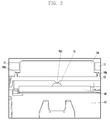
- FIG. 2 is a view for describing a structure of a home key of a conventional electronic device
- FIG. 3 is a view illustrating the home key of the conventional electronic device inclined to the right side.
- a home key 7 may be positioned between a front case 11 and a rear case 12.
- the home key 7 may include a body 14, a key base 13, and a switch 15.
- the switch 15 When a force of which the magnitude is equal to or larger than a predetermined level is applied to the switch 15, the switch 15 may generate an electric signal. Specifically, the switch 15 is elastically deformed by a user's pushing operation to be electrically connected with a contact on a Printed Circuit Board (PCB) 16. When the pushing is released, the switch 15 is returned to its original shape so that the electrical connection with the contact may be released.
- PCB Printed Circuit Board
- the body 14 forms an exterior of the home key 7 and may be formed from a hard material.
- the body 14 may be mounted on the front case 11 to be partly exposed to the outside of the front case 11.
- the body 14 may include a locking rim 14a that prevents the body 14 from being released from the front case 11.
- the key base 13 is coupled to the lower end of the body 14 so as to transmit the user's pushing force to the switch 15.
- the key base 13 may be formed of a soft material (e.g., rubber, silicon or the like).
- the key base 13 may have a pressing protrusion 13c formed on the bottom surface thereof so as to press the switch 15.
- the conventional home key 7 may have a structure with a protruding central portion. For this reason, the home key 7 may rock from side to side in a normal state where no force is applied thereto. For example, the home key 7 may be inclined to the right side as illustrated in FIG. 3 . Similarly, the home key 7 may also be inclined to the left side. Thus, the conventional home key 7 has a problem of rocking from side to side.
- Document GB2054270 discloses a device according to the preamble of claim 1.
- exemplary embodiments of the present disclosure have been made in an effort to solve the above-mentioned problems and provide an input device of an electronic device which is provided with a floating prevention mechanism capable of preventing floating (e.g., rocking from side to side) of the input device.
- an input device for an electronic device comprising a switch; a substrate comprising the switch; a body; a pressing protrusion arranged between a bottom surface of the body and the switch, and configured for pressing the switch when a pressing force is exerted onto the body; and a floating prevention arrangement extending in a direction away from the bottom surface of the body, and being configured and arranged so as to prevent the body from being rocked and/or to impede off-axial movement of the body with respect to a longitudinal axis extending in a direction along a height of the protrusion.
- An input device for an electronic device according to an exemplary embodiment of the present disclosure may include: a case, a body that is partially exposed to an outside of the case, a key base that is made of a soft material and coupled to a lower end of the body, a switch that is positioned below the key base and generates an electrical signal when pressed by a force that is equal to or larger than a predetermined magnitude, and a subtrate on which the switch is mounted.
- the key base may include a pressing prutrusion that is formed on a bottom surface of the key base and presses the switch, and floating prevention units that are made of a soft material and formed at opposite sides of the key base with respect to the pressing protrusion. The floating prevention units support the body to prevent the body from being rocked.
- the pressing protusion may have a height
- the switch may have a height
- the floating prevetion unit may have a height that is equal to or larger than the sum of the heights of the pressing protrusion and the switch.
- a hole may be formed in the key base, and one or more supporting portions may extend downward from a side wall of a hole and may be spaced apart from the bottom surface of the key base by a predetermined distance and may be configured to support the body.
- the floating prevention unit may be made of an elastic body of a first material and the key base may be formed of a second material, the first material being different from the second material.
- the first material may be selected from materials including, for example, a spring and a sponge.
- the floating prevention unit may be elastically deformed when pressed by the force that is equal to or larger than a predetermined magnitude and returned to an original state when the force is released.
- the force may correspond to the width, the thickness, the material, the number, and the shape of the supporting portions.
- the key base may further include a fixing unit that is configured to fix a position of the key base relative to the electronic device.
- the body and key base may be formed as a single structure such as through one of a dual injection molding and an insert injection molding.
- An input device for an electronic device may include a body that forms an external appearance of the input device and is partially exposed to the outside, a key base that is made of a soft material and coupled to a lower end of the body, a switch that is positioned below the key base and generates an electrical signal when pressed by a force that is equal to or larger than a predetermined magnitude, and a subtrate on which the switch is mounted.
- the key base may include a pressing protrusion that is formed on a bottom surface of the key base and presses the switch, and floating prevention units that are made of a soft material and formed at opposing sides of the key base with respect to the pressing protrusion.
- the floating prevention units extend from a bottom surace of the key base in a step shape to be partially contacted with the substrate, thereby supporting the body to prevent the body from being rocked.
- the floating prevention units may be formed of an elastic material and may be elastically deformed in response to being pressed by the force that is equal to or larger than the predetermined magnitude.
- the force may correspond to the size, shape, and material of the floating prevention units.
- an electronic sytem may include an input device.
- the input device may include a printed circuit board including a dome switch, and a body including a lower surface.
- the body may be linearly movable in a direction toward and away from the printed circuit board.
- a pressing protrusion may extend in a direction away from the lower surface of the body and may be configured to press the dome switch.
- a longintudinal axis may extend along a height of the pressing protrusion.
- One or more floating prevention units may extend in the direction of the longitudinal axis away from the lower surface of the body and may be configured to impede off-axial movement of the body with respect to the longitudinal axis.
- Each floating prevention unit may have a first height, the dome switch may have a second height and the pressing protrusion may have a third height.
- a first height of the floating prevention unit may be at least as large as the sume of the second and third heights.
- An application of a pressing force may electrically deform the floating prevention units.
- the system may further include a key base that is coupled to the lower surface of the body, and the key base may include the pressing protrusion and the one or more floating prevention units.
- An equal number of floating prevention units may be positioned at opposing sides of the pressing protrusion.
- the key base and the body may be integrally formed.
- the dome switch may generate an electrical signal when pressed by a force at least as large as a predetermined magnitude and the floating prevention units may be elastically deformed when pressed by the force.
- the deformation of the floating prevention units may be approximately equal such that the body translates in a substantally non-angled manner when acted upon by the force.
- the input device for an electronic device according to the present disclosure may be prevented from being rocked by being additionally provided with the floating prevention units made of a soft material on the key base.
- the input device for an electronic device according to the present disclosure may protect the switch from an external impact since the floating prevention units come in contact with the substrate where the switch is mounted, thereby supporting the input device.
- an electronic device is a device that includes at least one physical input device and may be, for example, a mobile communciation terminal, a smart phone, a PDA, a tablet PC, a hand-held PC, a PMP, or the like.
- An input device will be described using a home key of an electronic device.
- the exemplary embodiments of the present disclosure may be applied to various keys (for example, a volume key, a power key, or the like) rather than being limited to an application to the home key.
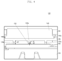
- FIG. 4 is a cross-sectional view illustrating an input device according to a first exemplary embodiment of the present disclosure.
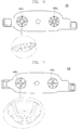
- FIG. 5 is a bottom view illustrating a key base of the input device according to the first exemplary embodiment of the present disclosure.
- FIG. 6 is a perspective view illustrating the key base of the input device according to the first exemplary embodiment of the present disclosure.
- FIG. 7 is a view illustrating an operated appearance of a floating prevention unit of the input device according to the first exemplary embodiment of the present disclosure.
- an input device 100 of the first exemplary embodiment of the present disclosure may be positioned between a front case 110 and a rear case 120.
- the input device 100 may include a body 140, a key base 130, and a switch 150.
- the switch 150 may generate an electric signal.
- the switch 150 may be a dome switch. Specifically, the switch 150 is elastically deformed by a pushing operation to be electrically connected with a contact on a PCB 160. When the pushing is released, the switch 150 is returned to its original shape so that the electrical connection with the contact may be released.
- the switch 150 may be mounted on a separate substrate (for example, Flexible Printed Circuit Board (FPCB)).
- FPCB Flexible Printed Circuit Board
- the body 140 forms an exterior of the input device 100 and may be formed of a hard material.
- the body 140 may be coupled to the front case 110 to be partially exposed to the outside and to be movable up and down. Specifically, the body 140 may be partially exposed through a hole formed in the front case 110 and partially positioned inside the front case 110.
- the body 140 extends in a horizontal direction by a predetermined length and may include a locking rim 140a that prevents the body 140 from being released from the front case 110.
- the key base 130 is positioned between the body 140 and the switch 150 and may transmit the user's pushing force to the switch 150.
- the key base 130 may be formed of a soft material (for example, rubber, silicon, or the like) so that the lifespan of the switch 150 may not be shortened as might occur over time when the body 140 formed of a hard material and directly presses the switch 150.
- the key base 130 may include a pressing protrusion 130c on the bottom surface thereof to press the switch 150. That is, the force generated by pushing the body 140 is transmitted to the switch 150 through the pressing protrusion 130c.
- the key base 130 may include fixing units 130d and 130e at opposite ends as illustrated in FIG. 5 .
- the fixing units 130d and 130e are structures for fixing the position of the input device 100. That is, the fixing units 130d and 130e serve to fix the input device 100 in such a manner that the input device 100 may not move horizonally forward, backward, left and right.
- the key base 130 may include a floating prevention or arrangement comprising floating prevention units 130a and 130b at opposite sides of the pressing protrusion 130c so as to prevent the key base 130 from left and right floating.
- the floating prevention units 130a and 130b may have a height higher than the pressing protrusion 130c.
- each of the floating prevention units 130a and 130b may come in contact with the printed circuit board 160 at one side of the lower end thereof.
- the height d3 of the floating prevention units 130a and 130b may have a value that is equal to or larger than the sum of the height d1 of the pressing protrusion 130c and the height d2 of the switch 150.
- the first exemplary embodiment of the present disclosure is not limited to this and the height of the floating prevention units 130a and 130b may have a tolerance of several milimeters. That is, the height d3 of the floating prevention units 130a and 130b may have a value which is similar (i.e., the same or approximately) to the sum of the height d1 of the pressing protrusion 130c and the height (d2) of the switch 150. Accordingly, as illustrated in FIG. 4 , the floating prevention units 130a and 130b may support the input device 100 at opposite sides with reference to the pressing protrusion 130c so that the input device 100 is not rocked. As a result, the input device 100 according to the first exemplary embodiment of the present disclosure may completely prevent occurrence of leftward and rightward movements.
- Each of the floating prevention units 130a and 130b may include one structure (hereinafter, "supporting portion") to support the input device 100.
- the supporting portion of each floating prevention unit 130a or 130b may extend downward from a side wall of a hole formed in the key base 130 to be spaced apart from the bottom surace of the key base 130 as illustrated in FIGs. 5 and 6 . That is, an empty space may exist between the supporting portion and the bottom surface of the key base 130.
- the supporting portion may have a shape of a two-tired step.
- the exemplary embodiment of the present disclosure is not limited to this and the supporting portion of each floating prevention unit 130a of 130b may have a shape of a one-tiered step of a three or more tiered step.
- the floating prevention units 130a and 130b may extend from the bottom surface of the key base 130. That is, no hole may be formed in the key base 130.
- the floating prevention units 130a and 130b may have elasticity.
- the floating prevention units 130a and 130b may maintain the shape as illustrated in FIG. 6 in a state where no force is applied thereto, and may be deformed in shape as illustrated in FIG. 7 in a pressed state where a force which is equal to or larger than a predetermined magnitude is applied thereto. Thereafter, when the force is released, the floating prevention units 130a and 130b may be returned to the origianal states thereof.
- the first exemplary embodiment of the present disclosure may minimize the decrease of a click feeling and prevent a problem of causing the body 140 to be floated (rocked) about the pressing protrusion 130c.
- the floating prevention units 130a and 130b according to the first exemplary embodiment of the present disclosure may protect the switch 150 from an external impact.
- the elastic force may be adjusted by properly changing the width, the thickness and the material of the floating prevention units 130a and 130b, and may adjust the click feeling of the input device 100 through the adjustment of the elastic force.
- the click feeling may be degraded since a large force is required in order to push the input device 100.
- the elastic force of the floating prevention units 130a and 130b is weak, the click feeling may be improved since a small force is requird for pushing the input device 100.
- a force for supporting the input device 100 is weak. Accordingly, it is desirable for the designer to properly change the width, the thickness and the material of the floating prevention units 130a and 130b depending on a situation.
- the floating prevention unit 130a and 130b and the key base 130 are integrally formed with the same material (for example, rubber), the present disclosure is not limited to this.
- the floating prevention units 130a and 130b may be formed as separate structures (for example, elastic bodies of a material that is different from the key base).
- the floating prevention units 130a and 130b may be formed of a spring, a sponge (for example, a high-elastic sponge or a compressed sponge), or the like.
- the body 140 and the key base 130 have been described above as being separate components, the body 140 and the key base 130 may be formed as a single or integral structure through dual injection molding, insert injection molding, or the like.
- FIG. 8 is a front view of a key base of an input device according to a second exemplary embodiment of the present disclosure
- FIG. 9 is a perspective view illustraing the key base of the input device according to the second exemplary embodiment of the present disclosure.
- each of the floating prevention units 230a and 230b of the key base 230 of of the input device according to the second exemplary embodiment of the present disclosure may include supporting portions arranged in a cross shape. That is, each floating prevention unit 230a or 230b of the key base 230 of the input device according to the second exemplary embodiment of the of the present disclosure may be configured by two supporting portions. Specifically, as illustrated in FIG. 9 , the supporting portions of each floating prevention unit 230a or 230b are connected to a hole formed in the key base 230 such that a cross portion thereof protrudes downwardly from the key base 230.
- the input device according to the second exemplary embodiment of the present disclosure is configured such that the elastic force of the floating prevention units 230a and 230b may be adjusted by increasing the number of supporting portions as described above. Meanwhile, the input device according to the second exemplary embodiment of the present disclosure is similar to the input device according to the first exemplary embodiment of the present disclosure described with reference to FIGs. 4 to 7 except that the shape of the key base 230 is changed. Accordingly, descriptions on the other components of the input device according to the second exemplary embodiment of the present disclosure will be omitted.
- FIG. 10 is a view illustraing a key base of an input device according to a third exemplary embodiment of the present disclosure.
- each of the floating prevention units 330a and 330b of the key base 330 of the input device according to the third exemplary embodiment of the present disclosure may be formed in a state where three supporting portions are joined with each other. At this time, the three supporting portions are connected to a hole formed in the key base 330 such that the cross portion of the three supporting portions of each floating prevention unit 330a or 330b protrudes downward from the key base 330. That is, similarly to the floating prevention units illustrated in FIGs. 8 and 9 , the input device according to the third exemplary embodiment of the present disclosure is configured such that the elastic force may be increased by increasing the number of the supporting portions that form each floating prevention unit 330a or 330b of the key base 330.
- the click feeling may be properly adjusted by changing the width, the thickness, the material, or the like of each supporting portion.
- the present disclosure is not limited to the configuration in which three supporting portions are joined with each other.
- each floating prevention unit according to the third exemplary embodiment of the present disclosure may be formed by joining four or more supporting portions.
- the third exemplary embodiment of the present disclosure is similar to the first exemplary embodiment of the present disclosure except that the shape of the key base 330 is changed. Accordingly, further detailed descriptions on the third exemplary embodiment of the present disclosure will be omitted.
- FIG. 11 is a view illsutrating a key base of an input device according to a fourth exemplary embodiment of the present disclosure.
- each of the floating prevention units 430a and 430b of the input device according to the fourth exemplary embodiment of the present disclosure may include supporting portions arranged in a cross shape. At this time, each supporting portion of each floating prevention unit 430a or 430b has a width which is narrowed in a direction away from the bottom surface of the key base 430.
- the input device according to the fourth exemplary embodiment of the present disclosure is configured such that the click feeling may be adjusted by adjustting the width of each supporting portion.
- the input device according to the fourth exemplary embodiment of the present disclosure is similar to the first exemplary embodiment of the present disclosure described above with reference to FIGs. 4 to 7 except that the shape of the key base 430 is changed. Accordingly, detailed descriptions on the other components of the input device according to the fourth exemplary embodiment of the present disclosure will be omitted.
Description
- The present disclosure relates generally to an input device, and more particularly, to an input device for an electronic device which includes a floating prevention mechnism.
- Recent electronic devices provide various functions such as a voice conversation function, a music playing function, a photographing function, and an internet connection. The electronic device involves but not exclusively a mobile communciation terminal, a smart phone, a Personal Digital Assistant (PDA), a tablet Personnel Computer (PC), a hand-held PC, a Portable Multimedia Player (PMP), or the like. Such an electronic device may include various input devices for controlling various functions, for example, physical keys, touch keys, touch screens, or the like. The electronic device usually includes one or more button type physical keys. For example, the electronic device may include a power key, a home key, a volume key, etc. which are formed as physical keys.
-
FIG. 1 is a front view of a conventional electronic device. - Referring to
FIG. 1 , the conventionalelectronic device 1 may have a rectangular shape. Theelectronic device 1 may include adisplay unit 2 on a front face thereof. In addition, theelectronic device 1 may include anilluminance sensor 3, aspeaker 4, and acamera 5 which are positioned at the upper end of thedisplay unit 2 as well as amenu key 6, ahome key 7, and acancel key 8 which are positioned at the lower end of thedisplay unit 2. Themenu key 6 and the cancelkey 8 of theelectronic device 1 may be formed as touch keys and thehome key 7 may be formed as a button type physical key. In addition, although not illustrated inFIG. 1 , a power key and a volume key may also be formed as button type physical keys. - Each of the above-mentioned physical keys of the electronic device has a structure that presses a dome switch mounted on a substrate so as to generate an electric signal. For this purpose, each physical key may have a protrusion for pressing the dome switch, which is formed at the center of the lower end thereof. That is, each of the physical keys takes a form in which the central portion protrudes. For this reason, the physical keys have a problem of rocking from side to side. Hereinafter, the problem will be described in more detail with reference to drawings.
-
FIG. 2 is a view for describing a structure of a home key of a conventional electronic device, andFIG. 3 is a view illustrating the home key of the conventional electronic device inclined to the right side. - Referring to
FIGs. 2 and3 , ahome key 7 may be positioned between afront case 11 and arear case 12. Thehome key 7 may include abody 14, akey base 13, and aswitch 15. - When a force of which the magnitude is equal to or larger than a predetermined level is applied to the
switch 15, theswitch 15 may generate an electric signal. Specifically, theswitch 15 is elastically deformed by a user's pushing operation to be electrically connected with a contact on a Printed Circuit Board (PCB) 16. When the pushing is released, theswitch 15 is returned to its original shape so that the electrical connection with the contact may be released. - The
body 14 forms an exterior of thehome key 7 and may be formed from a hard material. Thebody 14 may be mounted on thefront case 11 to be partly exposed to the outside of thefront case 11. Thebody 14 may include alocking rim 14a that prevents thebody 14 from being released from thefront case 11. - The
key base 13 is coupled to the lower end of thebody 14 so as to transmit the user's pushing force to theswitch 15. Thekey base 13 may be formed of a soft material (e.g., rubber, silicon or the like). Thekey base 13 may have apressing protrusion 13c formed on the bottom surface thereof so as to press theswitch 15. As described above, theconventional home key 7 may have a structure with a protruding central portion. For this reason, thehome key 7 may rock from side to side in a normal state where no force is applied thereto. For example, thehome key 7 may be inclined to the right side as illustrated inFIG. 3 . Similarly, thehome key 7 may also be inclined to the left side. Thus, theconventional home key 7 has a problem of rocking from side to side. - Document
GB2054270 claim 1. - Accordingly, exemplary embodiments of the present disclosure have been made in an effort to solve the above-mentioned problems and provide an input device of an electronic device which is provided with a floating prevention mechanism capable of preventing floating (e.g., rocking from side to side) of the input device. To solve the problem the invention provides for an input device for an electronic device, comprising a switch; a substrate comprising the switch; a body; a pressing protrusion arranged between a bottom surface of the body and the switch, and configured for pressing the switch when a pressing force is exerted onto the body; and a floating prevention arrangement extending in a direction away from the bottom surface of the body, and being configured and arranged so as to prevent the body from being rocked and/or to impede off-axial movement of the body with respect to a longitudinal axis extending in a direction along a height of the protrusion.
- An input device (e.g., a physical button) for an electronic device according to an exemplary embodiment of the present disclosure may include: a case, a body that is partially exposed to an outside of the case, a key base that is made of a soft material and coupled to a lower end of the body, a switch that is positioned below the key base and generates an electrical signal when pressed by a force that is equal to or larger than a predetermined magnitude, and a subtrate on which the switch is mounted. The key base may include a pressing prutrusion that is formed on a bottom surface of the key base and presses the switch, and floating prevention units that are made of a soft material and formed at opposite sides of the key base with respect to the pressing protrusion. The floating prevention units support the body to prevent the body from being rocked.
- The pressing protusion may have a height, the switch may have a height, and the floating prevetion unit may have a height that is equal to or larger than the sum of the heights of the pressing protrusion and the switch. A hole may be formed in the key base, and one or more supporting portions may extend downward from a side wall of a hole and may be spaced apart from the bottom surface of the key base by a predetermined distance and may be configured to support the body. The floating prevention unit may be made of an elastic body of a first material and the key base may be formed of a second material, the first material being different from the second material. The first material may be selected from materials including, for example, a spring and a sponge. The floating prevention unit may be elastically deformed when pressed by the force that is equal to or larger than a predetermined magnitude and returned to an original state when the force is released. The force may correspond to the width, the thickness, the material, the number, and the shape of the supporting portions. The key base may further include a fixing unit that is configured to fix a position of the key base relative to the electronic device. The body and key base may be formed as a single structure such as through one of a dual injection molding and an insert injection molding.
- An input device for an electronic device according to another exemplary embodiment of the present disclosrue may include a body that forms an external appearance of the input device and is partially exposed to the outside, a key base that is made of a soft material and coupled to a lower end of the body, a switch that is positioned below the key base and generates an electrical signal when pressed by a force that is equal to or larger than a predetermined magnitude, and a subtrate on which the switch is mounted. The key base may include a pressing protrusion that is formed on a bottom surface of the key base and presses the switch, and floating prevention units that are made of a soft material and formed at opposing sides of the key base with respect to the pressing protrusion. The floating prevention units extend from a bottom surace of the key base in a step shape to be partially contacted with the substrate, thereby supporting the body to prevent the body from being rocked.
- In an embodiment, the floating prevention units may be formed of an elastic material and may be elastically deformed in response to being pressed by the force that is equal to or larger than the predetermined magnitude. The force may correspond to the size, shape, and material of the floating prevention units.
- In an aspect of the present disclosure, an electronic sytem may include an input device. The input device may include a printed circuit board including a dome switch, and a body including a lower surface. The body may be linearly movable in a direction toward and away from the printed circuit board. A pressing protrusion may extend in a direction away from the lower surface of the body and may be configured to press the dome switch. A longintudinal axis may extend along a height of the pressing protrusion. One or more floating prevention units may extend in the direction of the longitudinal axis away from the lower surface of the body and may be configured to impede off-axial movement of the body with respect to the longitudinal axis. Each floating prevention unit may have a first height, the dome switch may have a second height and the pressing protrusion may have a third height. A first height of the floating prevention unit may be at least as large as the sume of the second and third heights. An application of a pressing force may electrically deform the floating prevention units. The system may further include a key base that is coupled to the lower surface of the body, and the key base may include the pressing protrusion and the one or more floating prevention units. An equal number of floating prevention units may be positioned at opposing sides of the pressing protrusion. The key base and the body may be integrally formed. The dome switch may generate an electrical signal when pressed by a force at least as large as a predetermined magnitude and the floating prevention units may be elastically deformed when pressed by the force. The deformation of the floating prevention units may be approximately equal such that the body translates in a substantally non-angled manner when acted upon by the force.
- The input device for an electronic device according to the present disclosure may be prevented from being rocked by being additionally provided with the floating prevention units made of a soft material on the key base. In addition, the input device for an electronic device according to the present disclosure may protect the switch from an external impact since the floating prevention units come in contact with the substrate where the switch is mounted, thereby supporting the input device.
- These and other aspects of the present disclosure are mor fully described hereinbelow with reference to the accompanying drawings.
- The above features and advantages of the present disclosure will be more apparent from the following detailed description in conjunction with the accompanying drawings, in which:
-
FIG. 1 is a view illustrating a conventional electronic device in accordance with the prior art; -
FIG. 2 is a view for describing a configuration of a home key of a conventional electronic device in accordance to the prior art; -
FIG. 3 is a view illustrating the home key of the conventional electronic device which is inclined to the right side in accordance with the prior art; -
FIG. 4 is a cross-sectional view illustrating an input device according to a first exemplary embodiment of the present disclosure; -
FIG. 5 is a bottom view illustrating a key base of the input device according to the first exemplary embodiment of the present disclosure; -
FIG. 6 is a perspective view illustrating the key base of the input device according to the first exemplary embodiment of the present disclosure; -
FIG. 7 is a perspective view of the input device as shown inFIG. 6 illustrating an operated appearance of a floating prevention unit; -
FIG. 8 is a front view illustrating a key base of an input device according to a second exemplary embodiment of the present disclosure; -
FIG. 9 is a perspective view illustrating the key base of the input device according to the second exemplary embodiemnt of the present disclosure; -
FIG. 10 is a view illustrating a key base of an input device according to a third exemplary embodiment of the present disclosure; and -
FIG. 11 is a view illustrating a key base of an input device according to a fourth exemplary embodiment of the present disclosure. - Hereinafter, exemplary embodiments of the present disclosure will be described with reference to the accompanying drawings. At this time, it shall be noted that in the accompanying drawings, the same or similar components are depicted by the same or similar reference numerals. Further, in the following description of the present description, a detailed description of known functions and configurations incorporated herein will be omitted when it may make the subject matter of the present description rather unclear. For the same reason, some components are exaggerated, omitted or schematically illustrated, and the size of each component is not intended to be to scale and therefore does not fully reflect the real size thereof. Moreover, the spacing between components as illustrated in the accompanying drawings is not intended to be to scale, and therefore the present disclosure is not limited by the spaces illustrated in the accompanying drawings.
- Meanwhile, the exemplary embodiments disclosed in the specification and drawings are merely presented to easily describe technical contents of the present disclosure and help the understanding of the present disclosure and are not intended to limit the scope of the present disclosure.
- In addition, an electronic device according to exemplary embodiments of the present disclosure is a device that includes at least one physical input device and may be, for example, a mobile communciation terminal, a smart phone, a PDA, a tablet PC, a hand-held PC, a PMP, or the like.
- An input device according to exemplary embodiments of the present disclosure will be described using a home key of an electronic device. However, the exemplary embodiments of the present disclosure may be applied to various keys (for example, a volume key, a power key, or the like) rather than being limited to an application to the home key.
- A structure of an input device according to a first exemplary embodiment of the present disclosure will be described with reference to
FIGS. 4-7 .FIG. 4 is a cross-sectional view illustrating an input device according to a first exemplary embodiment of the present disclosure.FIG. 5 is a bottom view illustrating a key base of the input device according to the first exemplary embodiment of the present disclosure.FIG. 6 is a perspective view illustrating the key base of the input device according to the first exemplary embodiment of the present disclosure.FIG. 7 is a view illustrating an operated appearance of a floating prevention unit of the input device according to the first exemplary embodiment of the present disclosure. - Referring to
FIGs. 4 to 7 , aninput device 100 of the first exemplary embodiment of the present disclosure may be positioned between afront case 110 and arear case 120. Theinput device 100 may include abody 140, akey base 130, and aswitch 150. - When a force which is equal to or larger than a predetermined magnitude is applied, the
switch 150 may generate an electric signal. Theswitch 150 may be a dome switch. Specifically, theswitch 150 is elastically deformed by a pushing operation to be electrically connected with a contact on aPCB 160. When the pushing is released, theswitch 150 is returned to its original shape so that the electrical connection with the contact may be released. Meanwhile, although it has been described above that theswitch 150 is mounted on thePCB 160, the present disclosure is not limited to this. For example, theswitch 150 may be mounted on a separate substrate (for example, Flexible Printed Circuit Board (FPCB)). - The
body 140 forms an exterior of theinput device 100 and may be formed of a hard material. Thebody 140 may be coupled to thefront case 110 to be partially exposed to the outside and to be movable up and down. Specifically, thebody 140 may be partially exposed through a hole formed in thefront case 110 and partially positioned inside thefront case 110. In addition, thebody 140 extends in a horizontal direction by a predetermined length and may include alocking rim 140a that prevents thebody 140 from being released from thefront case 110. - The
key base 130 is positioned between thebody 140 and theswitch 150 and may transmit the user's pushing force to theswitch 150. Thekey base 130 may be formed of a soft material (for example, rubber, silicon, or the like) so that the lifespan of theswitch 150 may not be shortened as might occur over time when thebody 140 formed of a hard material and directly presses theswitch 150. - The
key base 130 may include apressing protrusion 130c on the bottom surface thereof to press theswitch 150. That is, the force generated by pushing thebody 140 is transmitted to theswitch 150 through thepressing protrusion 130c. In addition, thekey base 130 may include fixingunits FIG. 5 . The fixingunits input device 100. That is, the fixingunits input device 100 in such a manner that theinput device 100 may not move horizonally forward, backward, left and right. - In addition, the
key base 130 may include a floating prevention or arrangement comprising floatingprevention units pressing protrusion 130c so as to prevent thekey base 130 from left and right floating. At this time, the floatingprevention units pressing protrusion 130c. For example, as illustrated inFIG. 4 , each of the floatingprevention units circuit board 160 at one side of the lower end thereof. The height d3 of the floatingprevention units pressing protrusion 130c and the height d2 of theswitch 150. However, the first exemplary embodiment of the present disclosure is not limited to this and the height of the floatingprevention units prevention units pressing protrusion 130c and the height (d2) of theswitch 150. Accordingly, as illustrated inFIG. 4 , the floatingprevention units input device 100 at opposite sides with reference to thepressing protrusion 130c so that theinput device 100 is not rocked. As a result, theinput device 100 according to the first exemplary embodiment of the present disclosure may completely prevent occurrence of leftward and rightward movements. - Each of the floating
prevention units input device 100. For example, the supporting portion of each floatingprevention unit key base 130 to be spaced apart from the bottom surace of thekey base 130 as illustrated inFIGs. 5 and6 . That is, an empty space may exist between the supporting portion and the bottom surface of thekey base 130. At this time, the supporting portion may have a shape of a two-tired step. However, the exemplary embodiment of the present disclosure is not limited to this and the supporting portion of each floatingprevention unit 130a of 130b may have a shape of a one-tiered step of a three or more tiered step. Further, the floatingprevention units key base 130. That is, no hole may be formed in thekey base 130. - The floating
prevention units prevention units FIG. 6 in a state where no force is applied thereto, and may be deformed in shape as illustrated inFIG. 7 in a pressed state where a force which is equal to or larger than a predetermined magnitude is applied thereto. Thereafter, when the force is released, the floatingprevention units body 140 to be floated (rocked) about thepressing protrusion 130c. In addition, the floatingprevention units switch 150 from an external impact. - The elastic force may be adjusted by properly changing the width, the thickness and the material of the floating
prevention units input device 100 through the adjustment of the elastic force. Specifically, there is an advantage in that no floating may occur when the elastic force of the floatingprevention units input device 100. On the contrary, when the elastic force of the floatingprevention units input device 100. However, there is a problem in that a force for supporting theinput device 100 is weak. Accordingly, it is desirable for the designer to properly change the width, the thickness and the material of the floatingprevention units - Although it has been described above that the floating
prevention unit key base 130 are integrally formed with the same material (for example, rubber), the present disclosure is not limited to this. For example, the floatingprevention units prevention units - Although the
body 140 and thekey base 130 have been described above as being separate components, thebody 140 and thekey base 130 may be formed as a single or integral structure through dual injection molding, insert injection molding, or the like. -
FIG. 8 is a front view of a key base of an input device according to a second exemplary embodiment of the present disclosure, andFIG. 9 is a perspective view illustraing the key base of the input device according to the second exemplary embodiment of the present disclosure. - Referring to
FIGs. 8 and 9 , each of the floatingprevention units key base 230 of of the input device according to the second exemplary embodiment of the present disclosure may include supporting portions arranged in a cross shape. That is, each floatingprevention unit key base 230 of the input device according to the second exemplary embodiment of the of the present disclosure may be configured by two supporting portions. Specifically, as illustrated inFIG. 9 , the supporting portions of each floatingprevention unit key base 230 such that a cross portion thereof protrudes downwardly from thekey base 230. The input device according to the second exemplary embodiment of the present disclosure is configured such that the elastic force of the floatingprevention units FIGs. 4 to 7 except that the shape of thekey base 230 is changed. Accordingly, descriptions on the other components of the input device according to the second exemplary embodiment of the present disclosure will be omitted. -
FIG. 10 is a view illustraing a key base of an input device according to a third exemplary embodiment of the present disclosure. - Referring to
FIG. 10 , each of the floatingprevention units key base 330 of the input device according to the third exemplary embodiment of the present disclosure may be formed in a state where three supporting portions are joined with each other. At this time, the three supporting portions are connected to a hole formed in thekey base 330 such that the cross portion of the three supporting portions of each floatingprevention unit key base 330. That is, similarly to the floating prevention units illustrated inFIGs. 8 and 9 , the input device according to the third exemplary embodiment of the present disclosure is configured such that the elastic force may be increased by increasing the number of the supporting portions that form each floatingprevention unit key base 330. At this time, as described above with reference toFIGs. 4 to 7 , the click feeling may be properly adjusted by changing the width, the thickness, the material, or the like of each supporting portion. However, the present disclosure is not limited to the configuration in which three supporting portions are joined with each other. For example, each floating prevention unit according to the third exemplary embodiment of the present disclosure may be formed by joining four or more supporting portions. Meanwhile, the third exemplary embodiment of the present disclosure is similar to the first exemplary embodiment of the present disclosure except that the shape of thekey base 330 is changed. Accordingly, further detailed descriptions on the third exemplary embodiment of the present disclosure will be omitted. -
FIG. 11 is a view illsutrating a key base of an input device according to a fourth exemplary embodiment of the present disclosure. - Referring to
FIG. 11 , each of the floatingprevention units prevention unit key base 430. The input device according to the fourth exemplary embodiment of the present disclosure is configured such that the click feeling may be adjusted by adusting the width of each supporting portion. Meanwhile, the input device according to the fourth exemplary embodiment of the present disclosure is similar to the first exemplary embodiment of the present disclosure described above with reference toFIGs. 4 to 7 except that the shape of thekey base 430 is changed. Accordingly, detailed descriptions on the other components of the input device according to the fourth exemplary embodiment of the present disclosure will be omitted. - Input devices for an electronic device according to the exemplary embodiments of the present disclosure have been described above with reference to the drawings and specific terms have been used.
Claims (10)
- An input device (100) for an electronic device, comprising:a case (110, 120);a body (140) that is partially exposed to an outside of the case;a key base (130; 230; 330; 430) that is made of a soft material and coupled to a lower surface of the body;a switch (150) that is positioned below the key base so as to generate an electrical signal when pressed by a force that is equal to or larger than a predetermined magnitude; anda substrate on which the switch is mounted,wherein the key base (130; 230; 330; 430) includes:a pressing protrusion (130c) that is formed on a bottom surface of the key base and is configured to press the switch; anda floating prevention arrangement comprising at least one floating prevention unit (130a, 130b; 230a, 230b; 330a, 330b; 430a, 430b) that is made of a soft material and formed at opposing sides of the key base with respect to the pressing protrusion to support the bodyso as to prevent the body from being rocked,characterized in that the floating prevention arrangement or unit (130a, 130b; 230a, 230b; 330a, 330b; 430a, 430b) includes:a hole formed in the key base (130; 230; 330; 430); andone or more supporting portions that extend downward from a side wall of the hole and are spaced apart from the bottom surface of the key base by a predetermined distance and are configured to support the body (140).
- The input device of claim 1, wherein the pressing protrusion (150c) has a height (d1) and the switch (150) has a height (d2), and wherein the floating prevention arrangement or unit (130a, 130b; 230a, 230b; 330a, 330b; 430a, 430b) has a height (d3) that is equal to or larger than a sum of the height (d1) of the pressing protrusion and the height (d2) of the switch.
- The input device of any one of claims 1 to 2, wherein the floating prevention arrangement or unit (130a, 130b; 230a, 230b; 330a, 330b; 430a, 430b) includes:one or more supporting portions that extend downward from the bottom surface of the key base (130; 230; 330; 430) and are configured to support the body (140).
- The input device of any one of claims 1 to 3, wherein the floating prevention arrangement or unit (130a, 130b; 230a, 230b; 330a, 330b; 430a, 430b) is made of a first material and the key base (130; 230; 330; 430) is formed from a second material, the first material being different from the second material.
- The input device of claim 4, wherein the first material includes an elastic body.
- The input device of any one of claims 1 to 5, wherein the input device is configured such that the floating prevention unit (130a, 130b; 230a, 230b; 330a, 330b; 430a, 430b) is elastically deformed when pressed by the force that is equal to or larger than the predetermined magnitude and returns to an original state when the force is released.
- The input device of any one of claims 1 to 6, wherein the force that is equal to or larger than the predetermined magnitude corresponds to a width, thickness, material, number, and/or shape of the supporting portions.
- The input device of any one of claims 1 to 7, wherein the key base (130; 230; 330; 430) further includes a fixing unit (130d, 130e) that is configured to fix a position of the key base relative to the case (110, 120).
- The input device of any one of claims 1 to 8, wherein the body (140) and the key base (130; 230; 330; 430) are formed as a single structure through one of a dual injection molding and an insert injection molding.
- An electronic device comprising the input device according to any one of the preceding claims.
Applications Claiming Priority (1)
| Application Number | Priority Date | Filing Date | Title |
|---|---|---|---|
| KR1020130040064A KR20140123194A (en) | 2013-04-11 | 2013-04-11 | Input apparatus for electronic device |
Publications (3)
| Publication Number | Publication Date |
|---|---|
| EP2790200A2 EP2790200A2 (en) | 2014-10-15 |
| EP2790200A3 EP2790200A3 (en) | 2014-11-19 |
| EP2790200B1 true EP2790200B1 (en) | 2016-02-03 |
Family
ID=50473045
Family Applications (1)
| Application Number | Title | Priority Date | Filing Date |
|---|---|---|---|
| EP14162815.6A Not-in-force EP2790200B1 (en) | 2013-04-11 | 2014-03-31 | Input apparatus for electronic device |
Country Status (6)
| Country | Link |
|---|---|
| US (1) | US20140305778A1 (en) |
| EP (1) | EP2790200B1 (en) |
| KR (1) | KR20140123194A (en) |
| CN (1) | CN104103442A (en) |
| AU (1) | AU2014201990A1 (en) |
| WO (1) | WO2014168382A1 (en) |
Families Citing this family (1)
| Publication number | Priority date | Publication date | Assignee | Title |
|---|---|---|---|---|
| KR102565839B1 (en) * | 2017-10-13 | 2023-08-10 | 엘에스오토모티브테크놀로지스 주식회사 | Vehicular multi-operating switching unit |
Family Cites Families (14)
| Publication number | Priority date | Publication date | Assignee | Title |
|---|---|---|---|---|
| JPS5924109Y2 (en) * | 1979-06-22 | 1984-07-17 | シチズン時計株式会社 | Push button structure for small portable devices |
| KR19980027628U (en) * | 1996-11-18 | 1998-08-05 | 김광호 | Button of electronics |
| US6774330B2 (en) * | 2001-03-27 | 2004-08-10 | Trw Inc. | Multi-stage push button switch apparatus |
| CN1255827C (en) * | 2001-12-28 | 2006-05-10 | 株式会社东芝 | Press button switch for elevator |
| CN2550887Y (en) * | 2002-02-04 | 2003-05-14 | 旭丽股份有限公司 | Spring sheet type key |
| CN2548245Y (en) * | 2002-04-22 | 2003-04-30 | 神基科技股份有限公司 | Keyboard |
| JP2004103375A (en) * | 2002-09-09 | 2004-04-02 | Alps Electric Co Ltd | Push-button switch |
| TW568337U (en) * | 2003-03-11 | 2003-12-21 | Inventec Multimedia & Telecom | Improved button structure |
| JP2005183306A (en) * | 2003-12-22 | 2005-07-07 | T An T:Kk | Push button structure of push switch |
| JP2006100084A (en) * | 2004-09-29 | 2006-04-13 | Matsushita Electric Ind Co Ltd | Multi-direction operating device |
| JP4960779B2 (en) * | 2007-07-02 | 2012-06-27 | ペンタックスリコーイメージング株式会社 | Operation member |
| TW200908049A (en) * | 2007-08-07 | 2009-02-16 | Darfon Electronics Corp | A key structure |
| US7964813B2 (en) * | 2009-05-27 | 2011-06-21 | Cheng Uei Precision Industry Co., Ltd. | Key structure |
| EP2282318B1 (en) * | 2009-07-29 | 2016-06-29 | Electrolux Home Products Corporation N.V. | Push button switch assembly |
-
2013
- 2013-04-11 KR KR1020130040064A patent/KR20140123194A/en not_active Application Discontinuation
-
2014
- 2014-03-31 EP EP14162815.6A patent/EP2790200B1/en not_active Not-in-force
- 2014-04-02 US US14/243,162 patent/US20140305778A1/en not_active Abandoned
- 2014-04-04 WO PCT/KR2014/002911 patent/WO2014168382A1/en active Application Filing
- 2014-04-08 AU AU2014201990A patent/AU2014201990A1/en not_active Abandoned
- 2014-04-09 CN CN201410140159.3A patent/CN104103442A/en active Pending
Also Published As
| Publication number | Publication date |
|---|---|
| EP2790200A2 (en) | 2014-10-15 |
| US20140305778A1 (en) | 2014-10-16 |
| KR20140123194A (en) | 2014-10-22 |
| CN104103442A (en) | 2014-10-15 |
| WO2014168382A1 (en) | 2014-10-16 |
| EP2790200A3 (en) | 2014-11-19 |
| AU2014201990A1 (en) | 2014-10-30 |
Similar Documents
| Publication | Publication Date | Title |
|---|---|---|
| US8263889B2 (en) | Manipulating apparatus and mobile terminal including the same | |
| US9292051B2 (en) | Touch pad input device | |
| US6686906B2 (en) | Tactile electromechanical data input mechanism | |
| US20100103611A1 (en) | Electronic device | |
| US9214295B2 (en) | Key structure | |
| CN102403147B (en) | Press key structure and electronic device comprising same | |
| CN102387678A (en) | Electronic device | |
| EP2034499A1 (en) | Switch responsive to see-saw key | |
| TW201714053A (en) | Touch pad module and electronic device | |
| CN106133866A (en) | Electricity key switch and the operating element with electric key switch | |
| JP2003045291A (en) | Operation button structure | |
| EP2790200B1 (en) | Input apparatus for electronic device | |
| US9715976B2 (en) | Keyboard device | |
| CN111223701B (en) | Key structure | |
| JP5376026B2 (en) | Push switch | |
| US10903025B1 (en) | Keyboard with vibration function | |
| JP6292624B2 (en) | Input device and electronic device | |
| US20160233861A1 (en) | Keyboard device | |
| JP2008311009A (en) | Press operation device | |
| JP2007207473A (en) | Electronic apparatus | |
| US20190096605A1 (en) | Mechanical key structure | |
| US9870883B2 (en) | Input device and electronic equipment | |
| KR200451842Y1 (en) | Low profile multi-directional key unit structure | |
| JP2010080330A (en) | Multidirectional input device | |
| WO2015111624A1 (en) | Input device, and electronic device provided with same |
Legal Events
| Date | Code | Title | Description |
|---|---|---|---|
| PUAI | Public reference made under article 153(3) epc to a published international application that has entered the european phase |
Free format text: ORIGINAL CODE: 0009012 |
|
| 17P | Request for examination filed |
Effective date: 20140331 |
|
| AK | Designated contracting states |
Kind code of ref document: A2 Designated state(s): AL AT BE BG CH CY CZ DE DK EE ES FI FR GB GR HR HU IE IS IT LI LT LU LV MC MK MT NL NO PL PT RO RS SE SI SK SM TR |
|
| AX | Request for extension of the european patent |
Extension state: BA ME |
|
| PUAL | Search report despatched |
Free format text: ORIGINAL CODE: 0009013 |
|
| AK | Designated contracting states |
Kind code of ref document: A3 Designated state(s): AL AT BE BG CH CY CZ DE DK EE ES FI FR GB GR HR HU IE IS IT LI LT LU LV MC MK MT NL NO PL PT RO RS SE SI SK SM TR |
|
| AX | Request for extension of the european patent |
Extension state: BA ME |
|
| RIC1 | Information provided on ipc code assigned before grant |
Ipc: H01H 13/705 20060101AFI20141013BHEP |
|
| R17P | Request for examination filed (corrected) |
Effective date: 20150519 |
|
| RBV | Designated contracting states (corrected) |
Designated state(s): AL AT BE BG CH CY CZ DE DK EE ES FI FR GB GR HR HU IE IS IT LI LT LU LV MC MK MT NL NO PL PT RO RS SE SI SK SM TR |
|
| GRAP | Despatch of communication of intention to grant a patent |
Free format text: ORIGINAL CODE: EPIDOSNIGR1 |
|
| INTG | Intention to grant announced |
Effective date: 20150729 |
|
| GRAS | Grant fee paid |
Free format text: ORIGINAL CODE: EPIDOSNIGR3 |
|
| GRAA | (expected) grant |
Free format text: ORIGINAL CODE: 0009210 |
|
| AK | Designated contracting states |
Kind code of ref document: B1 Designated state(s): AL AT BE BG CH CY CZ DE DK EE ES FI FR GB GR HR HU IE IS IT LI LT LU LV MC MK MT NL NO PL PT RO RS SE SI SK SM TR |
|
| REG | Reference to a national code |
Ref country code: GB Ref legal event code: FG4D |
|
| REG | Reference to a national code |
Ref country code: AT Ref legal event code: REF Ref document number: 774037 Country of ref document: AT Kind code of ref document: T Effective date: 20160215 Ref country code: CH Ref legal event code: EP |
|
| REG | Reference to a national code |
Ref country code: IE Ref legal event code: FG4D |
|
| REG | Reference to a national code |
Ref country code: DE Ref legal event code: R096 Ref document number: 602014000820 Country of ref document: DE |
|
| REG | Reference to a national code |
Ref country code: FR Ref legal event code: PLFP Year of fee payment: 3 |
|
| REG | Reference to a national code |
Ref country code: NL Ref legal event code: FP |
|
| REG | Reference to a national code |
Ref country code: LT Ref legal event code: MG4D |
|
| REG | Reference to a national code |
Ref country code: AT Ref legal event code: MK05 Ref document number: 774037 Country of ref document: AT Kind code of ref document: T Effective date: 20160203 |
|
| PG25 | Lapsed in a contracting state [announced via postgrant information from national office to epo] |
Ref country code: HR Free format text: LAPSE BECAUSE OF FAILURE TO SUBMIT A TRANSLATION OF THE DESCRIPTION OR TO PAY THE FEE WITHIN THE PRESCRIBED TIME-LIMIT Effective date: 20160203 Ref country code: NO Free format text: LAPSE BECAUSE OF FAILURE TO SUBMIT A TRANSLATION OF THE DESCRIPTION OR TO PAY THE FEE WITHIN THE PRESCRIBED TIME-LIMIT Effective date: 20160503 Ref country code: FI Free format text: LAPSE BECAUSE OF FAILURE TO SUBMIT A TRANSLATION OF THE DESCRIPTION OR TO PAY THE FEE WITHIN THE PRESCRIBED TIME-LIMIT Effective date: 20160203 Ref country code: GR Free format text: LAPSE BECAUSE OF FAILURE TO SUBMIT A TRANSLATION OF THE DESCRIPTION OR TO PAY THE FEE WITHIN THE PRESCRIBED TIME-LIMIT Effective date: 20160504 Ref country code: ES Free format text: LAPSE BECAUSE OF FAILURE TO SUBMIT A TRANSLATION OF THE DESCRIPTION OR TO PAY THE FEE WITHIN THE PRESCRIBED TIME-LIMIT Effective date: 20160203 |
|
| PG25 | Lapsed in a contracting state [announced via postgrant information from national office to epo] |
Ref country code: PT Free format text: LAPSE BECAUSE OF FAILURE TO SUBMIT A TRANSLATION OF THE DESCRIPTION OR TO PAY THE FEE WITHIN THE PRESCRIBED TIME-LIMIT Effective date: 20160603 Ref country code: SE Free format text: LAPSE BECAUSE OF FAILURE TO SUBMIT A TRANSLATION OF THE DESCRIPTION OR TO PAY THE FEE WITHIN THE PRESCRIBED TIME-LIMIT Effective date: 20160203 Ref country code: LV Free format text: LAPSE BECAUSE OF FAILURE TO SUBMIT A TRANSLATION OF THE DESCRIPTION OR TO PAY THE FEE WITHIN THE PRESCRIBED TIME-LIMIT Effective date: 20160203 Ref country code: PL Free format text: LAPSE BECAUSE OF FAILURE TO SUBMIT A TRANSLATION OF THE DESCRIPTION OR TO PAY THE FEE WITHIN THE PRESCRIBED TIME-LIMIT Effective date: 20160203 Ref country code: IS Free format text: LAPSE BECAUSE OF FAILURE TO SUBMIT A TRANSLATION OF THE DESCRIPTION OR TO PAY THE FEE WITHIN THE PRESCRIBED TIME-LIMIT Effective date: 20160603 Ref country code: BE Free format text: LAPSE BECAUSE OF NON-PAYMENT OF DUE FEES Effective date: 20160331 Ref country code: LT Free format text: LAPSE BECAUSE OF FAILURE TO SUBMIT A TRANSLATION OF THE DESCRIPTION OR TO PAY THE FEE WITHIN THE PRESCRIBED TIME-LIMIT Effective date: 20160203 Ref country code: RS Free format text: LAPSE BECAUSE OF FAILURE TO SUBMIT A TRANSLATION OF THE DESCRIPTION OR TO PAY THE FEE WITHIN THE PRESCRIBED TIME-LIMIT Effective date: 20160203 Ref country code: AT Free format text: LAPSE BECAUSE OF FAILURE TO SUBMIT A TRANSLATION OF THE DESCRIPTION OR TO PAY THE FEE WITHIN THE PRESCRIBED TIME-LIMIT Effective date: 20160203 |
|
| PG25 | Lapsed in a contracting state [announced via postgrant information from national office to epo] |
Ref country code: DK Free format text: LAPSE BECAUSE OF FAILURE TO SUBMIT A TRANSLATION OF THE DESCRIPTION OR TO PAY THE FEE WITHIN THE PRESCRIBED TIME-LIMIT Effective date: 20160203 Ref country code: EE Free format text: LAPSE BECAUSE OF FAILURE TO SUBMIT A TRANSLATION OF THE DESCRIPTION OR TO PAY THE FEE WITHIN THE PRESCRIBED TIME-LIMIT Effective date: 20160203 |
|
| REG | Reference to a national code |
Ref country code: DE Ref legal event code: R097 Ref document number: 602014000820 Country of ref document: DE |
|
| PG25 | Lapsed in a contracting state [announced via postgrant information from national office to epo] |
Ref country code: SM Free format text: LAPSE BECAUSE OF FAILURE TO SUBMIT A TRANSLATION OF THE DESCRIPTION OR TO PAY THE FEE WITHIN THE PRESCRIBED TIME-LIMIT Effective date: 20160203 Ref country code: RO Free format text: LAPSE BECAUSE OF FAILURE TO SUBMIT A TRANSLATION OF THE DESCRIPTION OR TO PAY THE FEE WITHIN THE PRESCRIBED TIME-LIMIT Effective date: 20160203 Ref country code: CZ Free format text: LAPSE BECAUSE OF FAILURE TO SUBMIT A TRANSLATION OF THE DESCRIPTION OR TO PAY THE FEE WITHIN THE PRESCRIBED TIME-LIMIT Effective date: 20160203 Ref country code: SK Free format text: LAPSE BECAUSE OF FAILURE TO SUBMIT A TRANSLATION OF THE DESCRIPTION OR TO PAY THE FEE WITHIN THE PRESCRIBED TIME-LIMIT Effective date: 20160203 |
|
| PLBE | No opposition filed within time limit |
Free format text: ORIGINAL CODE: 0009261 |
|
| STAA | Information on the status of an ep patent application or granted ep patent |
Free format text: STATUS: NO OPPOSITION FILED WITHIN TIME LIMIT |
|
| REG | Reference to a national code |
Ref country code: IE Ref legal event code: MM4A |
|
| PG25 | Lapsed in a contracting state [announced via postgrant information from national office to epo] |
Ref country code: BE Free format text: LAPSE BECAUSE OF FAILURE TO SUBMIT A TRANSLATION OF THE DESCRIPTION OR TO PAY THE FEE WITHIN THE PRESCRIBED TIME-LIMIT Effective date: 20160203 |
|
| 26N | No opposition filed |
Effective date: 20161104 |
|
| PG25 | Lapsed in a contracting state [announced via postgrant information from national office to epo] |
Ref country code: IE Free format text: LAPSE BECAUSE OF NON-PAYMENT OF DUE FEES Effective date: 20160331 |
|
| REG | Reference to a national code |
Ref country code: FR Ref legal event code: PLFP Year of fee payment: 4 |
|
| PG25 | Lapsed in a contracting state [announced via postgrant information from national office to epo] |
Ref country code: SI Free format text: LAPSE BECAUSE OF FAILURE TO SUBMIT A TRANSLATION OF THE DESCRIPTION OR TO PAY THE FEE WITHIN THE PRESCRIBED TIME-LIMIT Effective date: 20160203 Ref country code: BG Free format text: LAPSE BECAUSE OF FAILURE TO SUBMIT A TRANSLATION OF THE DESCRIPTION OR TO PAY THE FEE WITHIN THE PRESCRIBED TIME-LIMIT Effective date: 20160503 |
|
| PG25 | Lapsed in a contracting state [announced via postgrant information from national office to epo] |
Ref country code: MT Free format text: LAPSE BECAUSE OF FAILURE TO SUBMIT A TRANSLATION OF THE DESCRIPTION OR TO PAY THE FEE WITHIN THE PRESCRIBED TIME-LIMIT Effective date: 20160203 |
|
| REG | Reference to a national code |
Ref country code: CH Ref legal event code: PL |
|
| REG | Reference to a national code |
Ref country code: FR Ref legal event code: PLFP Year of fee payment: 5 |
|
| PG25 | Lapsed in a contracting state [announced via postgrant information from national office to epo] |
Ref country code: LI Free format text: LAPSE BECAUSE OF NON-PAYMENT OF DUE FEES Effective date: 20170331 Ref country code: CH Free format text: LAPSE BECAUSE OF NON-PAYMENT OF DUE FEES Effective date: 20170331 |
|
| PG25 | Lapsed in a contracting state [announced via postgrant information from national office to epo] |
Ref country code: HU Free format text: LAPSE BECAUSE OF FAILURE TO SUBMIT A TRANSLATION OF THE DESCRIPTION OR TO PAY THE FEE WITHIN THE PRESCRIBED TIME-LIMIT; INVALID AB INITIO Effective date: 20140331 |
|
| PG25 | Lapsed in a contracting state [announced via postgrant information from national office to epo] |
Ref country code: LU Free format text: LAPSE BECAUSE OF NON-PAYMENT OF DUE FEES Effective date: 20160331 Ref country code: CY Free format text: LAPSE BECAUSE OF FAILURE TO SUBMIT A TRANSLATION OF THE DESCRIPTION OR TO PAY THE FEE WITHIN THE PRESCRIBED TIME-LIMIT Effective date: 20160203 Ref country code: MK Free format text: LAPSE BECAUSE OF FAILURE TO SUBMIT A TRANSLATION OF THE DESCRIPTION OR TO PAY THE FEE WITHIN THE PRESCRIBED TIME-LIMIT Effective date: 20160203 Ref country code: MC Free format text: LAPSE BECAUSE OF FAILURE TO SUBMIT A TRANSLATION OF THE DESCRIPTION OR TO PAY THE FEE WITHIN THE PRESCRIBED TIME-LIMIT Effective date: 20160203 |
|
| PG25 | Lapsed in a contracting state [announced via postgrant information from national office to epo] |
Ref country code: TR Free format text: LAPSE BECAUSE OF FAILURE TO SUBMIT A TRANSLATION OF THE DESCRIPTION OR TO PAY THE FEE WITHIN THE PRESCRIBED TIME-LIMIT Effective date: 20160203 Ref country code: AL Free format text: LAPSE BECAUSE OF FAILURE TO SUBMIT A TRANSLATION OF THE DESCRIPTION OR TO PAY THE FEE WITHIN THE PRESCRIBED TIME-LIMIT Effective date: 20160203 |
|
| PGFP | Annual fee paid to national office [announced via postgrant information from national office to epo] |
Ref country code: NL Payment date: 20190221 Year of fee payment: 6 |
|
| PGFP | Annual fee paid to national office [announced via postgrant information from national office to epo] |
Ref country code: DE Payment date: 20190220 Year of fee payment: 6 Ref country code: GB Payment date: 20190221 Year of fee payment: 6 Ref country code: IT Payment date: 20190313 Year of fee payment: 6 |
|
| PGFP | Annual fee paid to national office [announced via postgrant information from national office to epo] |
Ref country code: FR Payment date: 20190225 Year of fee payment: 6 |
|
| REG | Reference to a national code |
Ref country code: DE Ref legal event code: R119 Ref document number: 602014000820 Country of ref document: DE |
|
| REG | Reference to a national code |
Ref country code: NL Ref legal event code: MM Effective date: 20200401 |
|
| PG25 | Lapsed in a contracting state [announced via postgrant information from national office to epo] |
Ref country code: NL Free format text: LAPSE BECAUSE OF NON-PAYMENT OF DUE FEES Effective date: 20200401 |
|
| PG25 | Lapsed in a contracting state [announced via postgrant information from national office to epo] |
Ref country code: DE Free format text: LAPSE BECAUSE OF NON-PAYMENT OF DUE FEES Effective date: 20201001 Ref country code: FR Free format text: LAPSE BECAUSE OF NON-PAYMENT OF DUE FEES Effective date: 20200331 |
|
| GBPC | Gb: european patent ceased through non-payment of renewal fee |
Effective date: 20200331 |
|
| PG25 | Lapsed in a contracting state [announced via postgrant information from national office to epo] |
Ref country code: GB Free format text: LAPSE BECAUSE OF NON-PAYMENT OF DUE FEES Effective date: 20200331 |
|
| PG25 | Lapsed in a contracting state [announced via postgrant information from national office to epo] |
Ref country code: IT Free format text: LAPSE BECAUSE OF NON-PAYMENT OF DUE FEES Effective date: 20200331 |