EP2034499A1 - Switch responsive to see-saw key - Google Patents
Switch responsive to see-saw key Download PDFInfo
- Publication number
- EP2034499A1 EP2034499A1 EP07707209A EP07707209A EP2034499A1 EP 2034499 A1 EP2034499 A1 EP 2034499A1 EP 07707209 A EP07707209 A EP 07707209A EP 07707209 A EP07707209 A EP 07707209A EP 2034499 A1 EP2034499 A1 EP 2034499A1
- Authority
- EP
- European Patent Office
- Prior art keywords
- push
- pivot point
- operation knob
- contact
- switch
- Prior art date
- Legal status (The legal status is an assumption and is not a legal conclusion. Google has not performed a legal analysis and makes no representation as to the accuracy of the status listed.)
- Withdrawn
Links
Images


Classifications
-
- H—ELECTRICITY
- H01—ELECTRIC ELEMENTS
- H01H—ELECTRIC SWITCHES; RELAYS; SELECTORS; EMERGENCY PROTECTIVE DEVICES
- H01H13/00—Switches having rectilinearly-movable operating part or parts adapted for pushing or pulling in one direction only, e.g. push-button switch
- H01H13/70—Switches having rectilinearly-movable operating part or parts adapted for pushing or pulling in one direction only, e.g. push-button switch having a plurality of operating members associated with different sets of contacts, e.g. keyboard
- H01H13/702—Switches having rectilinearly-movable operating part or parts adapted for pushing or pulling in one direction only, e.g. push-button switch having a plurality of operating members associated with different sets of contacts, e.g. keyboard with contacts carried by or formed from layers in a multilayer structure, e.g. membrane switches
- H01H13/705—Switches having rectilinearly-movable operating part or parts adapted for pushing or pulling in one direction only, e.g. push-button switch having a plurality of operating members associated with different sets of contacts, e.g. keyboard with contacts carried by or formed from layers in a multilayer structure, e.g. membrane switches characterised by construction, mounting or arrangement of operating parts, e.g. push-buttons or keys
- H01H13/7065—Switches having rectilinearly-movable operating part or parts adapted for pushing or pulling in one direction only, e.g. push-button switch having a plurality of operating members associated with different sets of contacts, e.g. keyboard with contacts carried by or formed from layers in a multilayer structure, e.g. membrane switches characterised by construction, mounting or arrangement of operating parts, e.g. push-buttons or keys characterised by the mechanism between keys and layered keyboards
-
- H—ELECTRICITY
- H01—ELECTRIC ELEMENTS
- H01H—ELECTRIC SWITCHES; RELAYS; SELECTORS; EMERGENCY PROTECTIVE DEVICES
- H01H13/00—Switches having rectilinearly-movable operating part or parts adapted for pushing or pulling in one direction only, e.g. push-button switch
- H01H13/02—Details
- H01H13/12—Movable parts; Contacts mounted thereon
- H01H13/20—Driving mechanisms
-
- H—ELECTRICITY
- H01—ELECTRIC ELEMENTS
- H01H—ELECTRIC SWITCHES; RELAYS; SELECTORS; EMERGENCY PROTECTIVE DEVICES
- H01H13/00—Switches having rectilinearly-movable operating part or parts adapted for pushing or pulling in one direction only, e.g. push-button switch
- H01H13/50—Switches having rectilinearly-movable operating part or parts adapted for pushing or pulling in one direction only, e.g. push-button switch having a single operating member
- H01H13/52—Switches having rectilinearly-movable operating part or parts adapted for pushing or pulling in one direction only, e.g. push-button switch having a single operating member the contact returning to its original state immediately upon removal of operating force, e.g. bell-push switch
-
- H—ELECTRICITY
- H01—ELECTRIC ELEMENTS
- H01H—ELECTRIC SWITCHES; RELAYS; SELECTORS; EMERGENCY PROTECTIVE DEVICES
- H01H2205/00—Movable contacts
- H01H2205/016—Separate bridge contact
- H01H2205/022—Conductive rubber
-
- H—ELECTRICITY
- H01—ELECTRIC ELEMENTS
- H01H—ELECTRIC SWITCHES; RELAYS; SELECTORS; EMERGENCY PROTECTIVE DEVICES
- H01H2215/00—Tactile feedback
- H01H2215/004—Collapsible dome or bubble
- H01H2215/006—Only mechanical function
-
- H—ELECTRICITY
- H01—ELECTRIC ELEMENTS
- H01H—ELECTRIC SWITCHES; RELAYS; SELECTORS; EMERGENCY PROTECTIVE DEVICES
- H01H2215/00—Tactile feedback
- H01H2215/004—Collapsible dome or bubble
- H01H2215/022—Asymmetric; Elliptic; Square
-
- H—ELECTRICITY
- H01—ELECTRIC ELEMENTS
- H01H—ELECTRIC SWITCHES; RELAYS; SELECTORS; EMERGENCY PROTECTIVE DEVICES
- H01H2221/00—Actuators
- H01H2221/008—Actuators other then push button
- H01H2221/016—Lever; Rocker
Definitions
- the present invention relates to a switch using a contact rubber switch operated by a seesaw-key which is used for operating home electric appliances, mobile phones and in-vehicle units.
- Some switches mounted on home electric appliances and in-vehicle units use a contact rubber switch.
- the switch of this type has a key top or an operation knob operated by a user and the rubber switch which is pushed down by the key top and the operation knob.
- a movable contact formed on an under surface of the rubber switch contacts a fixed contact formed on a circuit board, providing conduction between the contacts.
- Some of these switches are constructed such that the operation knob is rotated around a pivot point.
- the operation knob when the key top is being pushed down to rotate the operation knob, the operation knob contacts the contact rubber switch in a tilted state.
- the movable contact sometimes goes down without remaining in a horizontal posture, causing insufficient conduction between the contacts.
- the movable contact provides the conduction by deformation of the rubber during the pushing operation. In this operation, it is preferable to give a clear clicking, feeling which teaches completion of the pushing operation to a user.
- An object of the present invention is to provide a switch which has advantages such as simple structure, reliable conduction, or excellent click feeling when operated.
- a switch according to the present invention is a switch which is pushed down so as to conduct a fixed contact formed on a circuit board and comprises: a key top to be pushed down; an operation knob pushed down by the key top to rotate around a pivot point, having a working portion; and a contact rubber switch pushed down by the working portion of the operation knob; wherein the rubber switch is provided with a push-button portion having an upper surface pushed down by the working portion of the operation knob and an under surface formed with a movable contact; and a skirt portion extending obliquely downward from an edge of the push-button portion, in which the skirt portion has a thinner portion on the side of the pivot point of the operation knob and a thicker portion on the opposite side of the pivot point of the operation knob and the push-button portion has an upper surface inclined upward toward the side of the pivot point of the operation knob.
- the operation knob In the generally used switches constructed such that the operation knob is rotated around a pivot point, the operation knob contacts the push-button portion in a tilted state during most of the rotating operation. Accordingly, the movable contact does not go down straight, causing insufficient conduction.
- the skirt portion is constructed so as to have a thinner portion on the side of the pivot point of the operation knob and a thicker portion on the opposite side of the pivot point of the operation knob. Furthermore, the upper surface of the push-button portion inclines upward toward the side of the pivot point of the operation knob. As s result, it becomes possible to contact the movable contact with the fixed contact with a parallel posture to cause sufficient conduction, described later referring to as Fig.3 in detail.
- the working portion of the operation knob contacts the edge of the push-button portion of the rubber switch, on the side of the pivot point of the operation knob, to deform the skirt portion on the side of the pivot point at the initial step of the push down operation, and then the working portion contacts the edge of the push-button portion of the rubber switch, on the opposite side of the pivot point, to be pushed down and to deform the skirt portion on the opposite side of the pivot point.
- the upper portion of the push-button portion is made to come in contact with the working portion of the operation knob evenly.
- the push-button portion of the contact rubber switch may have a central portion having a surface inclined upward toward the side of the pivot point; a peripheral portion surrounding the central portion other than an edge on the pivot point side; and a slit having a thin base separating the central portion from the peripheral portion, in which the working portion of the operation knob contacts only the upper surface of the central portion and does not contact the peripheral portion when comes in contact with the push-button portion of the contact rubber switch.
- the central portion of the push-button portion is easy to rotate with respect to the base of the slit when the push-button portion is pushed down by the working portion of the operation knob whereby it becomes possible to contact the upper surfaces of the central portion and the peripheral portion with the working portion of the operation knob.
- the contact rubber switch may be operated in such a manner that the movable contact tilts downward toward the side of the pivot point when the key top is being applied with preload; an angle of the movable contact becomes small gradually during a push down operation of the key top; and the movable contact comes contact with the fixed contact with substantially a parallel posture at the final step of the push down operation.
- the thicker skirt portion on the opposite side of the pivot point of the operation knob is suddenly deformed at the final step of the push down operation to cause a click feeling teaching a completion of the push down operation to the user.
- the key top is applied with pressure produced by the sudden deformation of the thicker skirt portion thereby to generate a clear click feeling teaching completion of the push down operation to the user.
- the switch of the present invention it becomes possible to contact the movable contact formed on the push-button portion in surface with the fixed contact formed on the circuit board in a parallel posture. Furthermore, as compared with the generally used switches, only the contact rubber switch is modified and number of parts does not increase. So, a switch with stably operation ability and simple structure can be provided.
- the key top 5 has a cylindrical body 5a, a flange portion 5b extending outward from an under surface of the body 5a and a pusher rod 5c protruding vertically from a center of the under surface of the body 5a.
- the key top 5 is slidably mounted upward and downward to a case 4 covering the board 2.
- the case 4 is formed with a circular opening 4a which allows passing of the body 5a of the key top 5.
- a peripheral recess 4b having a suitable height is formed, into which the flange portion 5b is stored.
- the flange portion 5b slides in the recess 4b upward and downward to guide the key top 5 in upward and downward directions (in a stroke direction).
- the operation knob 6 is arranged under the key top 5, the operation knob 6 is arranged.
- the operation knob 6 is a flat plate shaped member and is rotatably attached to the case 4 at the proximal portion 6a.
- the pusher rod 5c of the key top 5 comes in contact with the distal portion (working portion) 6b of the operation knob 6.
- the distal portion 6b of the operation knob 6 is pushed down by the pusher rod 5c to rotate the operation knob 5 around a pivot point P.
- the pivot point P is positioned lower than the highest point of the contact rubber switch 10.
- the operation knob 6 rotates from a slightly upward tilted state to a slightly downward tilted state with respect to a level line.
- the contact rubber switch 10 is disposed under the distal portion (working portion) 6b of the operation knob 6, the contact rubber switch 10 is disposed.
- the rubber switch 10 has a supporting portion 11 mounted on the board 2, a push-button portion 12 pushed down by the working portion 6b of the operation knob 6 at the upper surface thereof and a skirt portion 13 extending obliquely downward from a peripheral edge of the push-button portion 12 to the supporting portion 11.
- a movable contact 14 is formed on an under surface of the push-button portion 12. The movable contact 14 is positioned above the fixed contact 3 formed on the board 2.
- the contact rubber switch 10 has the supporting portion 11 mounted on the board 2, the push-button portion 12 pushed down by the working portion 6b of the operation knob 6 at the upper surface thereof and the skirt portion 13 extending obliquely downward from the peripheral edge of the pusher button portion 12 to the supporting portion 11.
- the portions are formed integrally using elastic rubber such as silicone rubber.
- the supporting portion 11 is mounted on the surface of the board 2.
- the supporting portion 11 is formed with an opening 11a for exposing the fixed contact 3 formed on the board 2.
- the push-button portion 12 is a substantially rectangular solid shaped member and has a main body 12a positioned on the side of the pivot point P of the operation knob 6 (on the pivot point side, on the right hand side in the figure) and a secondary body 12b positioned on the opposite side of the pivot point P (on the opposite side of the pivot point).
- the main body 12a has an upper surface 12c inclined upward toward the side of the pivot point P; the secondary body 12b has a substantially horizontal flat upper surface 12d.
- the inclined upper surface 12c makes up about two thirds of a total area of the upper surface of the push-button portion 12 and the flat upper surface 12d makes up about one third of the total area.
- the highest point of the upper surface of the push-button portion 12 (an edge 12e on the pivot point side) is positioned slightly higher than the pivot point P of the operation knob 6 in a free state in which the rubber switch 10 is not pushed down.
- a cylindrical projection 12g projects downward.
- the projection 12g has a substantially flat under surface (in substantially parallel to the fixed contact 3) on which the movable contact 14 is formed.
- the movable contact 14 is formed by gold plating or applying a conductive material such as metal and carbon on the under surface of the projection 12g, for example.
- a center of the movable contact 14 is positioned on an approximate center of the inclined upper surface 12c.
- An under surface of the secondary body 12b is positioned higher than the under surface of the main body 12a (the movable contact 14).
- the skirt portion 13 extends from the peripheral edge of the push-button portion 12 obliquely downward and outward toward the edge of the opening 11a of the supporting portion 11.
- a skirt portion 13a extending from the edge on the opposite side of the pivot point, one of four edges around the push-button portion 12, has a thickness thicker than that of the other skirt portions 13b, 13c and 13d extending from the other three edges.
- the skirt portions 13c on the three edges other than the edge on the opposite side of the pivot point extend from the side surface of the main body 12a obliquely downward.
- the skirt portion 13a on the edge on the opposite side of the pivot point extends from the peripheral edge of the under surface of the secondary body 12b obliquely downward.
- a slit 13e is formed so as to keep the supporting portion 11 without influence of the deformation force of the skirt portion 13 when the push-button portion 12 is pushed down.
- the supporting portion 11 may be applied with the deformation force thereby to be shifted.
- the slit 13e since the slit 13e disperses the push down force, a click feeling may be affected. Depending on variation of products, the slit 13e may not be formed.
- the operation knob 6 Since the pivot point P of the operation knob 6 is positioned slightly lower than the highest point (the edge 12e) of the upper surface of the push-button portion 12, the operation knob 6 contacts the push-button portion 12 in a slightly upward tilted state from the pivot point P.
- a switching operation of the switch will be described.
- Fig.3A in a state in which the rubber switch 10 is assembled in the case 4, the flange portion 5b of the key top 5 abuts against the uppermost wall of the recess 4b of the case 4.
- the pusher rod 5c of the key top 5 contacts the working portion 6b of the operation knob 6 over an approximate center of the upper surface 12c of the main body 12a of the push-button portion 12 (an approximate center of the movable contact 14).
- the operation knob 6 rotates into a substantially horizontal posture and thus the push-button portion 12 is applied with load (preload). Applying the preload to the push-button portion 12 prevents backlash of the push-button portion 12.
- a repulsive force produced by the rubber switch 10 applied with the load pushes the key top 5 up and the push-up force is suppressed by the flange portion 5b.
- the skirt portion 13c on the pivot point side is deformed as bends outward because of its thin thickness and thus easy-deformable property.
- the skirt portion 13a on the opposite side of the pivot point is hardly deformed because of its thickness and thus less-deformable property. Accordingly, the push-button portion 12 rotates around the edge 12e on the pivot point side clockwise in the figure and then comes in contact with the operation knob 6 at the edge 12f on the opposite side of the pivot point. And, there is a space between a boundary portion of the inclined upper surface 12c and the flat upper surface 12d of the push-button portion 12, and the under surface of the operation knob 6.
- the movable contact 14 formed on the under surface of the push-button portion 12 tilts downward toward the side of the pivot point with respect to a level state shown in Fig.2A (a state parallel to the fixed contact 3).
- the skirt portion 13b on the pivot point side having a thinner thickness and thus easy-deformable property, is deformed as bends further outward.
- the skirt portion 13a on the opposite side of the pivot point having a thicker thickness than the skirt portion 13b on the pivot point side and thus less-deformable property, is also deformed as bends outward slightly.
- the push-button portion 12 is deformed elastically so that the inclined upper surface 12c and the flat upper surface 12d of the push-button portion 12 contacts in surface with the under surface of the operation knob 6.
- the movable contact 14 still tilts downward toward the side of the pivot point; however, an angle of the tilt to a level line becomes smaller compared with the state shown in Fig.2A .
- the key top 5 is pushed down until the flange portion 5b abuts against the undermost wall of the recess 4b of the case 4 to push down the push-button portion 12 by the operation knob 6.
- the operation knob 6 rotates into a state tilted further downward compared with the state shown in Fig.3B (further downward with respect to a level line).
- the less-deformable skirt portion 13a on the opposite side of the pivot point can not sustain the push-down force to be deformed suddenly.
- the skirt portion 13a on the opposite side of the pivot point has a thicker thickness and also extends obliquely downward from the under surface of the secondary body 12b of the push-button portion 12, it is not bent outward so much.
- the easy-deformable skirt portion 13b on the pivot point side bends outward to be deformed further.
- the push-button portion 12 is pushed down while moving inward (in a direction of the pivot point P). Then, an angle of the movable contact 14 with respect to a level line becomes almost zero resulting in that the movable contact 14 parallel contacts in surface with the fixed contact 3.
- Figs.4 are views showing a contact rubber switch included in a switch according to the second embodiment of the present invention
- Fig.4A is a side view
- Fig.4B is a plain view
- Figs.5 are views showing operating state of the switch of Fig.4
- the switch 1' has the same structure as the switch 1 of Fig.1 except for a structure of a push-button portion 22.
- the push-button portion 22 has a round hill-shaped central portion 22a and a peripheral portion 22b separated by a slit 22c from the central portion 22a.
- the parts having the same structure and function as the parts of the switch 1 of Fig.1 are indicated with the same number as Fig.1 and will not be described.
- the central portion 22a corresponding to the main body 12a of the push-button portion 12 of Fig.1 , has an upper surface 22d inclined upward toward the side of the pivot point P. From an under surface of the central portion 22a, a cylindrical projection 22f projects downward. The projection 22f has a substantially flat under surface (in substantially parallel to the fixed contact 3) on which the movable contact 14 is formed.
- the peripheral portion 22b corresponding to the secondary body 12b of the push-button portion 12 of Fig.1 , surrounds the peripheral edge of the central portion 22a other than the edge on the pivot point side.
- the peripheral portion 22b has a flat upper surface having a same height as a height of the undermost portion of the upper surface 22d of the central portion 22a.
- the slit 22c has a thin bottom 22g.
- the under surface of the working portion 6b of the operation knob 6 contacts only the central portion 22a, specifically the edge 22e on the pivot point side, and does not contact the peripheral potion 22b.
- the operation knob 6 tilts upward from the pivot point P and contacts the push-button portion 22.
- a switching operation of the switch will be described.
- the push-button portion 22 rotates around the edge 22e on the pivot point side clockwise in the figure. Since the slit 22c is formed between the central portion 22a and the peripheral portion 22b, the bottom 22g of the slit 22c is easily deformable. Accordingly, the central portion 22a is easily rotatable to the bottom 22g of the slit 22c clockwise in the figure. As a result, it becomes possible to contact the under surface of the operation knob 6 with the upper surface 22d of the central portion 22a and the upper surface of the peripheral portion 22b of the push-button portion 22 tightly. And, the movable contact 14 tilts downward toward the side of the pivot point P.
- the push-button portion 22 When the push-button portion 22 is formed with the slit 22c like this embodiment, all area of the upper surface of the push-button portion 22 can contact the under surface of the working portion 6b of the operation knob 5. However, the slit 22c does not always have to be formed.
Landscapes
- Push-Button Switches (AREA)
- Rotary Switch, Piano Key Switch, And Lever Switch (AREA)
Abstract
Description
- The present invention relates to a switch using a contact rubber switch operated by a seesaw-key which is used for operating home electric appliances, mobile phones and in-vehicle units.
- Some switches mounted on home electric appliances and in-vehicle units use a contact rubber switch. The switch of this type has a key top or an operation knob operated by a user and the rubber switch which is pushed down by the key top and the operation knob. When the key top is pushed down by a finger to push down the rubber switch, a movable contact formed on an under surface of the rubber switch contacts a fixed contact formed on a circuit board, providing conduction between the contacts.
- Some of these switches are constructed such that the operation knob is rotated around a pivot point. In the switch of this type, when the key top is being pushed down to rotate the operation knob, the operation knob contacts the contact rubber switch in a tilted state. In this instance, the movable contact sometimes goes down without remaining in a horizontal posture, causing insufficient conduction between the contacts. In some contact rubber switches, the movable contact provides the conduction by deformation of the rubber during the pushing operation. In this operation, it is preferable to give a clear clicking, feeling which teaches completion of the pushing operation to a user.
- In view of the points, various types of improved seesaw switches have been proposed. One of the seesaw switches has an inclined movable contact surface which becomes parallel to a fixed contact when the movable contact is pushed down (referring to Patent literature 1). Or, another seesaw switch has a projecting contact which contacts the operation knob with a small contact area (referring to Patent literature 2). And, still another seesaw switch is proposed, which has a pusher pushed down by an operation knob to press a movable contact formed on a rubber contact switch, in which the rubber contact switch is provided with an elastic member with which the operation knob comes in contact before the operation knob contacts the pusher (referring to Patent literature 3). However, these switches have problems in which a sufficient click feeling of the switch can not generated when pushed down and they needs increased numbers of parts causing a complex structure.
- Patent literature 1: Unexamined Japanese Utility Model Publication
Sho63-60234 - Patent literature 2: Unexamined Japanese Utility Model Publication
Sho63-112724 - Patent literature 2: Japanese Patent Publication
2005-5139 - An object of the present invention is to provide a switch which has advantages such as simple structure, reliable conduction, or excellent click feeling when operated.
- A switch according to the present invention is a switch which is pushed down so as to conduct a fixed contact formed on a circuit board and comprises: a key top to be pushed down; an operation knob pushed down by the key top to rotate around a pivot point, having a working portion; and a contact rubber switch pushed down by the working portion of the operation knob; wherein the rubber switch is provided with a push-button portion having an upper surface pushed down by the working portion of the operation knob and an under surface formed with a movable contact; and a skirt portion extending obliquely downward from an edge of the push-button portion, in which the skirt portion has a thinner portion on the side of the pivot point of the operation knob and a thicker portion on the opposite side of the pivot point of the operation knob and the push-button portion has an upper surface inclined upward toward the side of the pivot point of the operation knob.
- In the generally used switches constructed such that the operation knob is rotated around a pivot point, the operation knob contacts the push-button portion in a tilted state during most of the rotating operation. Accordingly, the movable contact does not go down straight, causing insufficient conduction. So, in order to solve the problem, in the present invention, the skirt portion is constructed so as to have a thinner portion on the side of the pivot point of the operation knob and a thicker portion on the opposite side of the pivot point of the operation knob. Furthermore, the upper surface of the push-button portion inclines upward toward the side of the pivot point of the operation knob. As s result, it becomes possible to contact the movable contact with the fixed contact with a parallel posture to cause sufficient conduction, described later referring to as
Fig.3 in detail. - Preferably, the working portion of the operation knob contacts the edge of the push-button portion of the rubber switch, on the side of the pivot point of the operation knob, to deform the skirt portion on the side of the pivot point at the initial step of the push down operation, and then the working portion contacts the edge of the push-button portion of the rubber switch, on the opposite side of the pivot point, to be pushed down and to deform the skirt portion on the opposite side of the pivot point.
- In this case, at the initial step (the preload step), since the skirt portion on the side of the pivot point is deformed such that the push-button portion tilts downward toward the side of the pivot point, the upper portion of the push-button portion is made to come in contact with the working portion of the operation knob evenly.
- In the present invention, the push-button portion of the contact rubber switch may have a central portion having a surface inclined upward toward the side of the pivot point; a peripheral portion surrounding the central portion other than an edge on the pivot point side; and a slit having a thin base separating the central portion from the peripheral portion, in which the working portion of the operation knob contacts only the upper surface of the central portion and does not contact the peripheral portion when comes in contact with the push-button portion of the contact rubber switch.
- In this case, the central portion of the push-button portion is easy to rotate with respect to the base of the slit when the push-button portion is pushed down by the working portion of the operation knob whereby it becomes possible to contact the upper surfaces of the central portion and the peripheral portion with the working portion of the operation knob.
- In the present invention, the contact rubber switch may be operated in such a manner that the movable contact tilts downward toward the side of the pivot point when the key top is being applied with preload; an angle of the movable contact becomes small gradually during a push down operation of the key top; and the movable contact comes contact with the fixed contact with substantially a parallel posture at the final step of the push down operation.
- Preferably, the thicker skirt portion on the opposite side of the pivot point of the operation knob is suddenly deformed at the final step of the push down operation to cause a click feeling teaching a completion of the push down operation to the user.
- In this case, at the final step of the push down operation, the key top is applied with pressure produced by the sudden deformation of the thicker skirt portion thereby to generate a clear click feeling teaching completion of the push down operation to the user.
- As described above, according to the switch of the present invention, it becomes possible to contact the movable contact formed on the push-button portion in surface with the fixed contact formed on the circuit board in a parallel posture. Furthermore, as compared with the generally used switches, only the contact rubber switch is modified and number of parts does not increase. So, a switch with stably operation ability and simple structure can be provided.
- Hereinafter, preferred embodiments of the present in vention will be described in detail with reference to the accompanying drawings.
-
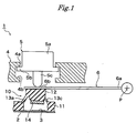
Fig.1 is a side view showing a switch according to the first embodiment of the present invention. -
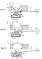
Figs.2 are views showing a structure of a contact rubber switch included in the switch ofFig.1 ,Fig.2(A) is a side view andFig.2(B) is a plain view. -
Figs.3 are side views showing operating state of the switch ofFig.1 . - The
key top 5 has acylindrical body 5a, aflange portion 5b extending outward from an under surface of thebody 5a and apusher rod 5c protruding vertically from a center of the under surface of thebody 5a. Thekey top 5 is slidably mounted upward and downward to acase 4 covering theboard 2. Specifically, thecase 4 is formed with acircular opening 4a which allows passing of thebody 5a of thekey top 5. On a peripheral wall of theopening 4a, aperipheral recess 4b having a suitable height is formed, into which theflange portion 5b is stored. Theflange portion 5b slides in therecess 4b upward and downward to guide thekey top 5 in upward and downward directions (in a stroke direction). - Under the
key top 5, theoperation knob 6 is arranged. Theoperation knob 6 is a flat plate shaped member and is rotatably attached to thecase 4 at theproximal portion 6a. Thepusher rod 5c of thekey top 5 comes in contact with the distal portion (working portion) 6b of theoperation knob 6. On pushing down thekey top 5, thedistal portion 6b of theoperation knob 6 is pushed down by thepusher rod 5c to rotate theoperation knob 5 around a pivot point P. As described later, the pivot point P is positioned lower than the highest point of thecontact rubber switch 10. In this example, theoperation knob 6 rotates from a slightly upward tilted state to a slightly downward tilted state with respect to a level line. - Under the distal portion (working portion) 6b of the
operation knob 6, thecontact rubber switch 10 is disposed. Therubber switch 10 has a supportingportion 11 mounted on theboard 2, a push-button portion 12 pushed down by the workingportion 6b of theoperation knob 6 at the upper surface thereof and askirt portion 13 extending obliquely downward from a peripheral edge of the push-button portion 12 to the supportingportion 11. On an under surface of the push-button portion 12, amovable contact 14 is formed. Themovable contact 14 is positioned above the fixedcontact 3 formed on theboard 2. When the push-button portion 12 of therubber switch 10 is pushed down by the workingportion 6b of theoperation knob 6, the push-button portion 12 moves downward to cause contact of themovable contact 14 with the fixedcontact 3, providing conduction of the pair of contacts of the fixedcontact 3. - Referring to
Fig.2 , the structure of thecontact rubber switch 10 will be described.
As described above, thecontact rubber switch 10 has the supportingportion 11 mounted on theboard 2, the push-button portion 12 pushed down by the workingportion 6b of theoperation knob 6 at the upper surface thereof and theskirt portion 13 extending obliquely downward from the peripheral edge of thepusher button portion 12 to the supportingportion 11. The portions are formed integrally using elastic rubber such as silicone rubber. - The supporting
portion 11 is mounted on the surface of theboard 2. The supportingportion 11 is formed with anopening 11a for exposing the fixedcontact 3 formed on theboard 2. - The push-
button portion 12 is a substantially rectangular solid shaped member and has amain body 12a positioned on the side of the pivot point P of the operation knob 6 (on the pivot point side, on the right hand side in the figure) and asecondary body 12b positioned on the opposite side of the pivot point P (on the opposite side of the pivot point). Themain body 12a has anupper surface 12c inclined upward toward the side of the pivot point P; thesecondary body 12b has a substantially horizontal flatupper surface 12d. In this example, the inclinedupper surface 12c makes up about two thirds of a total area of the upper surface of the push-button portion 12 and the flatupper surface 12d makes up about one third of the total area. The highest point of the upper surface of the push-button portion 12 (anedge 12e on the pivot point side) is positioned slightly higher than the pivot point P of theoperation knob 6 in a free state in which therubber switch 10 is not pushed down. - From an under surface of the
main body 12a, acylindrical projection 12g projects downward. Theprojection 12g has a substantially flat under surface (in substantially parallel to the fixed contact 3) on which themovable contact 14 is formed. Themovable contact 14 is formed by gold plating or applying a conductive material such as metal and carbon on the under surface of theprojection 12g, for example. A center of themovable contact 14 is positioned on an approximate center of the inclinedupper surface 12c.
An under surface of thesecondary body 12b is positioned higher than the under surface of themain body 12a (the movable contact 14). - The
skirt portion 13 extends from the peripheral edge of the push-button portion 12 obliquely downward and outward toward the edge of theopening 11a of the supportingportion 11. Askirt portion 13a extending from the edge on the opposite side of the pivot point, one of four edges around the push-button portion 12, has a thickness thicker than that of theother skirt portions
Furthermore, as shown inFig.2A , theskirt portions 13c on the three edges other than the edge on the opposite side of the pivot point extend from the side surface of themain body 12a obliquely downward. On the contrary, theskirt portion 13a on the edge on the opposite side of the pivot point extends from the peripheral edge of the under surface of thesecondary body 12b obliquely downward.
Around theskirt portions skirt portion 13c on the side of the pivot point of theoperation knob 6, aslit 13e is formed so as to keep the supportingportion 11 without influence of the deformation force of theskirt portion 13 when the push-button portion 12 is pushed down. When theslit 13e is not formed, the supportingportion 11 may be applied with the deformation force thereby to be shifted. And, when theslit 13e is formed, since theslit 13e disperses the push down force, a click feeling may be affected. Depending on variation of products, theslit 13e may not be formed. - In a free state of the
operation knob 6, indicated by an image line inFig.2A , (in a state in which theoperation knob 6 contacts the upper surface of thecontact rubber switch 10 and thecontact rubber switch 10 is applied with the operation knob's own weight only), the under surface of the workingportion 6b of theknob 6 contacts the upper surface of the push-button portion 12, specifically the under surface of the workingportion 6b of theoperation knob 6 contacts theedge 12e on the side of the pivot point only and does not contact theedge 12f on the opposite side of the pivot point. Since the pivot point P of theoperation knob 6 is positioned slightly lower than the highest point (theedge 12e) of the upper surface of the push-button portion 12, theoperation knob 6 contacts the push-button portion 12 in a slightly upward tilted state from the pivot point P. - Referring to
Fig.3 , a switching operation of the switch will be described.
As shown inFig.3A , in a state in which therubber switch 10 is assembled in thecase 4, theflange portion 5b of thekey top 5 abuts against the uppermost wall of therecess 4b of thecase 4. Thepusher rod 5c of the key top 5 contacts the workingportion 6b of theoperation knob 6 over an approximate center of theupper surface 12c of themain body 12a of the push-button portion 12 (an approximate center of the movable contact 14). And, theoperation knob 6 rotates into a substantially horizontal posture and thus the push-button portion 12 is applied with load (preload). Applying the preload to the push-button portion 12 prevents backlash of the push-button portion 12. Conversely, a repulsive force produced by therubber switch 10 applied with the load pushes the key top 5 up and the push-up force is suppressed by theflange portion 5b. - When the push-
button portion 12 is pushed down by theoperation knob 6, theskirt portion 13c on the pivot point side is deformed as bends outward because of its thin thickness and thus easy-deformable property. On the contrary, theskirt portion 13a on the opposite side of the pivot point is hardly deformed because of its thickness and thus less-deformable property. Accordingly, the push-button portion 12 rotates around theedge 12e on the pivot point side clockwise in the figure and then comes in contact with theoperation knob 6 at theedge 12f on the opposite side of the pivot point. And, there is a space between a boundary portion of the inclinedupper surface 12c and the flatupper surface 12d of the push-button portion 12, and the under surface of theoperation knob 6. Themovable contact 14 formed on the under surface of the push-button portion 12 tilts downward toward the side of the pivot point with respect to a level state shown inFig.2A (a state parallel to the fixed contact 3). - As shown in
Fig.3B , when thekey top 5 is pushed down to push down the push-button portion 12 by theoperation knob 6, theoperation knob 6 rotates into a state tilted slightly downward from the pivot point (downward with respect to a level line). - Then, the
skirt portion 13b on the pivot point side, having a thinner thickness and thus easy-deformable property, is deformed as bends further outward. At the same time, theskirt portion 13a on the opposite side of the pivot point, having a thicker thickness than theskirt portion 13b on the pivot point side and thus less-deformable property, is also deformed as bends outward slightly. And, the push-button portion 12 is deformed elastically so that the inclinedupper surface 12c and the flatupper surface 12d of the push-button portion 12 contacts in surface with the under surface of theoperation knob 6. And, themovable contact 14 still tilts downward toward the side of the pivot point; however, an angle of the tilt to a level line becomes smaller compared with the state shown inFig.2A . - Finally, as shown in
Fig.3C , thekey top 5 is pushed down until theflange portion 5b abuts against the undermost wall of therecess 4b of thecase 4 to push down the push-button portion 12 by theoperation knob 6. Theoperation knob 6 rotates into a state tilted further downward compared with the state shown inFig.3B (further downward with respect to a level line). - As a result, the less-
deformable skirt portion 13a on the opposite side of the pivot point can not sustain the push-down force to be deformed suddenly. However, since theskirt portion 13a on the opposite side of the pivot point has a thicker thickness and also extends obliquely downward from the under surface of thesecondary body 12b of the push-button portion 12, it is not bent outward so much. On the contrary, the easy-deformable skirt portion 13b on the pivot point side bends outward to be deformed further. And, the push-button portion 12 is pushed down while moving inward (in a direction of the pivot point P). Then, an angle of themovable contact 14 with respect to a level line becomes almost zero resulting in that themovable contact 14 parallel contacts in surface with the fixedcontact 3. - As described above, since the
movable contact 14 formed on the push-button portion 12 contacts in surface with the fixedcontact 3 formed on thecircuit board 2, contact failure between the contacts will not occur. And, at the final step shown inFig.3C , thekey top 5 is applied with a pressure produced by the suddenly deformation of thethick skirt portion 13a, providing a clear click sensation to the user. - When the
key top 5 is released from the pressure applied thereto, theskirt portion 13 returns to its original shape by its elasticity. And, theoperation knob 6 is pushed up by the push-button portion 12 until theflange portion 5b abuts against the uppermost wall of therecess 4b of thecase 4. -
Figs.4 are views showing a contact rubber switch included in a switch according to the second embodiment of the present invention,Fig.4A is a side view andFig.4B is a plain view.
Figs.5 are views showing operating state of the switch ofFig.4
The switch 1' has the same structure as theswitch 1 ofFig.1 except for a structure of a push-button portion 22. In this embodiment, the push-button portion 22 has a round hill-shapedcentral portion 22a and aperipheral portion 22b separated by aslit 22c from thecentral portion 22a. InFigs.4 and5 , the parts having the same structure and function as the parts of theswitch 1 ofFig.1 are indicated with the same number asFig.1 and will not be described. - The
central portion 22a, corresponding to themain body 12a of the push-button portion 12 ofFig.1 , has anupper surface 22d inclined upward toward the side of the pivot point P. From an under surface of thecentral portion 22a, acylindrical projection 22f projects downward. Theprojection 22f has a substantially flat under surface (in substantially parallel to the fixed contact 3) on which themovable contact 14 is formed.
Theperipheral portion 22b, corresponding to thesecondary body 12b of the push-button portion 12 ofFig.1 , surrounds the peripheral edge of thecentral portion 22a other than the edge on the pivot point side. Theperipheral portion 22b has a flat upper surface having a same height as a height of the undermost portion of theupper surface 22d of thecentral portion 22a. And, theslit 22c has athin bottom 22g. - As shown in
Fig.4A , in a free state in which theoperation knob 6 is not applied with pressure, the under surface of the workingportion 6b of theoperation knob 6 contacts only thecentral portion 22a, specifically theedge 22e on the pivot point side, and does not contact theperipheral potion 22b. Theoperation knob 6 tilts upward from the pivot point P and contacts the push-button portion 22. - Referring to
Fig.5 , a switching operation of the switch will be described.
In a preload state shown inFig.5A , as withFig.3A , the push-button portion 22 rotates around theedge 22e on the pivot point side clockwise in the figure. Since theslit 22c is formed between thecentral portion 22a and theperipheral portion 22b, the bottom 22g of theslit 22c is easily deformable. Accordingly, thecentral portion 22a is easily rotatable to the bottom 22g of theslit 22c clockwise in the figure. As a result, it becomes possible to contact the under surface of theoperation knob 6 with theupper surface 22d of thecentral portion 22a and the upper surface of theperipheral portion 22b of the push-button portion 22 tightly. And, themovable contact 14 tilts downward toward the side of the pivot point P. - As shown in
Fig.5B , when thekey top 5 is pushed down to push down the push-button portion 22 by theoperation knob 6, theoperation knob 6 rotates into a state tilted slightly downward with respect to the pivot point P. Themovable contact 14 still tilts downward toward the side of the pivot point; however, an angle of the tilt with respect to a level line becomes smaller than the state shown inFig.5A . - Then, as shown in
Fig.5C , when thekey top 5 is pushed down undermost to push down the push-button portion 12 by theoperation knob 6, as withFig.3C , themovable contact 14 contacts the fixedcontact 3 in a substantially level posture. At the same time, theskirt portion 13 is deformed, as withFig.3C . - When the push-
button portion 22 is formed with theslit 22c like this embodiment, all area of the upper surface of the push-button portion 22 can contact the under surface of the workingportion 6b of theoperation knob 5. However, theslit 22c does not always have to be formed. -
-
Fig.1 is a side view showing a switch according to the first embodiment of the present invention; -
Figs.2 are views showing a structure of a contact rubber switch included in the switch ofFig.1 ,Fig.2(A) is a side view andFig.2(B) is a plain view; -
Figs.3 are side views showing operating state of the switch ofFig.1 ; -
Figs.4 are views showing a contact rubber switch included in a switch according to the second embodiment of the present invention,Fig.4A is a side view andFig.4B is a plain view; and -
Figs.5 are views showing operating state of the switch ofFig.4 . -
1 switch 2 circuit board 3 fixed contact 4 case 5 key top 6 operation knob 10, 10' contact rubber switch 11 supporting portion 12,22 push- button portion 13 skirt portion 14 movable contact
Claims (5)
- A switch pushed down so as to conduct a fixed contact formed on a circuit board comprising:a key top to be pushed down;an operation knob pushed down by the key top to rotate around a pivot point, having a working portion; anda contact rubber switch pushed down by the working portion of the operation knob;wherein the rubber switch is provided with a push-button portion having an upper surface pushed down by the working portion of the operation knob and an under surface formed with a movable contact; and a skirt portion extending obliquely downward from an edge of the push-button portion,in which the skirt portion has a thinner portion on the side of the pivot point of the operation knob and a thicker portion on the opposite side of the pivot point of the operation knob andthe push-button portion has an upper surface inclined upward toward the side of the pivot point of the operation knob.
- A switch according to claim 1,
wherein the working portion of the operation knob contacts the edge of the push-button portion of the rubber switch, on the side of the pivot point of the operation knob, to deform the skirt portion on the side of the pivot point at the initial step of the push down operation, and then
the working portion contacts the edge of the push-button portion of the rubber switch, on the opposite side of the pivot point, to be pushed down and to deform the skirt portion on the opposite side of the pivot point. - A switch according to claim 1,
wherein the push-button portion of the contact rubber switch has
a central portion having a surface inclined upward toward the side of the pivot point;
a peripheral portion surrounding the central portion other than an edge on the pivot point side; and
a slit having a thin base separating the central portion from the peripheral portion,
in which the working portion of the operation knob contacts only the upper surface of the central portion and does not contact the peripheral portion when comes in contact with the push-button portion of the contact rubber switch. - A switch according to any one of claims 1 to 3,
wherein the contact rubber switch is operated in such a manner that
the movable contact tilts downward toward the side of the pivot point when the key top is being applied with preload;
an angle of the movable contact becomes small gradually during a push down operation of the key top; and
the movable contact comes contact with the fixed contact with substantially a parallel posture at the final step of the push down operation. - A switch according to any one of claims 1 to 4,
wherein the thicker skirt portion on the opposite side of the pivot point of the operation knob is suddenly deformed at the final step of the push down operation to cause a click feeling teaching a completion of the push down operation to the user.
Applications Claiming Priority (2)
| Application Number | Priority Date | Filing Date | Title |
|---|---|---|---|
| JP2006172205 | 2006-06-22 | ||
| PCT/JP2007/050946 WO2007148446A1 (en) | 2006-06-22 | 2007-01-23 | Switch responsive to see-saw key |
Publications (2)
| Publication Number | Publication Date |
|---|---|
| EP2034499A1 true EP2034499A1 (en) | 2009-03-11 |
| EP2034499A4 EP2034499A4 (en) | 2012-01-11 |
Family
ID=38833192
Family Applications (1)
| Application Number | Title | Priority Date | Filing Date |
|---|---|---|---|
| EP07707209A Withdrawn EP2034499A4 (en) | 2006-06-22 | 2007-01-23 | Switch responsive to see-saw key |
Country Status (5)
| Country | Link |
|---|---|
| US (1) | US8008593B2 (en) |
| EP (1) | EP2034499A4 (en) |
| KR (1) | KR101312136B1 (en) |
| CN (1) | CN101473394B (en) |
| WO (1) | WO2007148446A1 (en) |
Cited By (4)
| Publication number | Priority date | Publication date | Assignee | Title |
|---|---|---|---|---|
| DE102010027799A1 (en) * | 2010-04-15 | 2011-10-20 | BSH Bosch und Siemens Hausgeräte GmbH | Operating device for a domestic appliance and domestic appliance with an operating device |
| EP2400664B1 (en) * | 2010-06-24 | 2013-11-06 | Sick Ag | Method for producing an optoelectronic sensor with an operating element |
| EP4089702A1 (en) * | 2021-05-12 | 2022-11-16 | Nintendo Co., Ltd. | Controller and key structure |
| IT202100031763A1 (en) * | 2021-12-20 | 2023-06-20 | Bitron Spa | INNOVATIVE SNAP-ON SILICONE DOME, CONTROL DEVICE FOR SWITCHING DEVICES AND RELATED SWITCHING DEVICE |
Families Citing this family (6)
| Publication number | Priority date | Publication date | Assignee | Title |
|---|---|---|---|---|
| CN102129928B (en) * | 2010-01-20 | 2013-11-27 | 和硕联合科技股份有限公司 | Key and electronic device applying same |
| WO2012153587A1 (en) * | 2011-05-10 | 2012-11-15 | 株式会社コバック | Two-stage switch |
| JP6155580B2 (en) * | 2012-09-11 | 2017-07-05 | オムロン株式会社 | Operation switch |
| CN103811216B (en) * | 2013-11-12 | 2015-10-21 | 苏州达方电子有限公司 | There is the keyboard of button storage function |
| CN107833777B (en) * | 2017-12-04 | 2020-10-02 | 漳州聚安美电气科技有限公司 | Short-stroke microswitch |
| TWI702626B (en) * | 2018-03-30 | 2020-08-21 | 英屬開曼群島商康而富控股股份有限公司 | Touch button with better pressing feel |
Citations (4)
| Publication number | Priority date | Publication date | Assignee | Title |
|---|---|---|---|---|
| DE3044414A1 (en) * | 1980-11-26 | 1982-06-24 | Licentia Gmbh | Electrical switch operated by key pressure - consists of embossed dome bulging from parent plastics sheet |
| FR2554630A1 (en) * | 1983-11-04 | 1985-05-10 | Thomson Brandt | Contactor of the push button type and its use on key pads. |
| JPH0458924U (en) * | 1990-09-25 | 1992-05-20 | ||
| EP1677325A2 (en) * | 2004-12-28 | 2006-07-05 | Brother Kogyo Kabushiki Kaisha | Push-button switch |
Family Cites Families (19)
| Publication number | Priority date | Publication date | Assignee | Title |
|---|---|---|---|---|
| US4492829A (en) * | 1982-02-25 | 1985-01-08 | Rogers Corporation | Tactile membrane keyboard with asymmetrical tactile key elements |
| JPS618821A (en) * | 1984-06-22 | 1986-01-16 | 松下電器産業株式会社 | Switch |
| US4604509A (en) * | 1985-02-01 | 1986-08-05 | Honeywell Inc. | Elastomeric push button return element for providing enhanced tactile feedback |
| US4771139A (en) * | 1986-06-27 | 1988-09-13 | Desmet Gregory L | Keyboard with metal cover and improved switches |
| JPS6360234A (en) | 1986-08-29 | 1988-03-16 | High Frequency Heattreat Co Ltd | Driving method for roll electrode for electrical heating |
| JPS63112724A (en) | 1986-10-29 | 1988-05-17 | Yukiya Sato | Method and apparatus for production of carbonized fiber cloth |
| JPH072158B2 (en) | 1990-06-28 | 1995-01-18 | 三洋電機株式会社 | Floor suction |
| US5228561A (en) * | 1991-04-01 | 1993-07-20 | Hewlett-Packard Company | Long traveling button switch with enhanced user feedback |
| JP2595132Y2 (en) * | 1992-02-14 | 1999-05-24 | ブラザー工業株式会社 | Key switch |
| JP3299041B2 (en) * | 1994-06-20 | 2002-07-08 | 株式会社河合楽器製作所 | Electronic musical instrument keyboard device |
| JPH0822738A (en) | 1994-07-05 | 1996-01-23 | Sega Enterp Ltd | Multistage push-switch |
| US5564560A (en) * | 1995-06-07 | 1996-10-15 | Garmin Corporation | Dual function button |
| JP2000067698A (en) * | 1998-08-20 | 2000-03-03 | Olympus Optical Co Ltd | Switch operating rubber member |
| KR100342959B1 (en) * | 1998-12-31 | 2002-07-05 | 양윤홍 | Keypad for cellular phone and method of manufacturing same |
| JP3941357B2 (en) | 2000-08-21 | 2007-07-04 | 松下電器産業株式会社 | Pushbutton switch and composite switch using the same |
| JP2002175746A (en) * | 2000-12-06 | 2002-06-21 | Yazaki Corp | Multi-stage click switch |
| US6940030B2 (en) * | 2003-04-03 | 2005-09-06 | Minebea Co., Ltd. | Hinge key switch |
| JP4217546B2 (en) | 2003-06-12 | 2009-02-04 | 株式会社東海理化電機製作所 | switch |
| FR2913524B1 (en) * | 2007-03-05 | 2009-04-17 | Itt Mfg Enterprises Inc | ELECTRICAL SWITCH WITH VARIABLE RECALL EFFORT. |
-
2007
- 2007-01-23 WO PCT/JP2007/050946 patent/WO2007148446A1/en active Application Filing
- 2007-01-23 US US12/305,415 patent/US8008593B2/en not_active Expired - Fee Related
- 2007-01-23 CN CN2007800226010A patent/CN101473394B/en not_active Expired - Fee Related
- 2007-01-23 KR KR1020087030851A patent/KR101312136B1/en not_active IP Right Cessation
- 2007-01-23 EP EP07707209A patent/EP2034499A4/en not_active Withdrawn
Patent Citations (4)
| Publication number | Priority date | Publication date | Assignee | Title |
|---|---|---|---|---|
| DE3044414A1 (en) * | 1980-11-26 | 1982-06-24 | Licentia Gmbh | Electrical switch operated by key pressure - consists of embossed dome bulging from parent plastics sheet |
| FR2554630A1 (en) * | 1983-11-04 | 1985-05-10 | Thomson Brandt | Contactor of the push button type and its use on key pads. |
| JPH0458924U (en) * | 1990-09-25 | 1992-05-20 | ||
| EP1677325A2 (en) * | 2004-12-28 | 2006-07-05 | Brother Kogyo Kabushiki Kaisha | Push-button switch |
Non-Patent Citations (1)
| Title |
|---|
| See also references of WO2007148446A1 * |
Cited By (6)
| Publication number | Priority date | Publication date | Assignee | Title |
|---|---|---|---|---|
| DE102010027799A1 (en) * | 2010-04-15 | 2011-10-20 | BSH Bosch und Siemens Hausgeräte GmbH | Operating device for a domestic appliance and domestic appliance with an operating device |
| WO2011141262A1 (en) | 2010-04-15 | 2011-11-17 | BSH Bosch und Siemens Hausgeräte GmbH | Operating device for a household appliance and household appliance comprising an operating device |
| EP2400664B1 (en) * | 2010-06-24 | 2013-11-06 | Sick Ag | Method for producing an optoelectronic sensor with an operating element |
| EP4089702A1 (en) * | 2021-05-12 | 2022-11-16 | Nintendo Co., Ltd. | Controller and key structure |
| US11951387B2 (en) | 2021-05-12 | 2024-04-09 | Nintendo Co., Ltd. | Controller and key structure |
| IT202100031763A1 (en) * | 2021-12-20 | 2023-06-20 | Bitron Spa | INNOVATIVE SNAP-ON SILICONE DOME, CONTROL DEVICE FOR SWITCHING DEVICES AND RELATED SWITCHING DEVICE |
Also Published As
| Publication number | Publication date |
|---|---|
| CN101473394A (en) | 2009-07-01 |
| CN101473394B (en) | 2012-03-28 |
| WO2007148446A1 (en) | 2007-12-27 |
| KR20090023611A (en) | 2009-03-05 |
| EP2034499A4 (en) | 2012-01-11 |
| JPWO2007148446A1 (en) | 2009-11-12 |
| US20090277765A1 (en) | 2009-11-12 |
| JP4044957B2 (en) | 2008-02-06 |
| US8008593B2 (en) | 2011-08-30 |
| KR101312136B1 (en) | 2013-09-26 |
Similar Documents
| Publication | Publication Date | Title |
|---|---|---|
| US8008593B2 (en) | Switch for seesaw key | |
| TWI475587B (en) | Keyboard and method making the same | |
| TW201515038A (en) | Low travel switch assembly | |
| US20100253633A1 (en) | Fingertip tactile-sense input device | |
| JP2007188682A (en) | Key switch device | |
| US5967298A (en) | Keyboard device | |
| US6390699B1 (en) | Keyboard with moveable base plate providing key travel | |
| TW201735083A (en) | Keyboard | |
| US6545238B2 (en) | Key device with a scissors mechanism | |
| US11670465B2 (en) | Key structure | |
| US6534736B1 (en) | Key switch of keyboard unit | |
| US10242819B1 (en) | Mechanical key structure | |
| CN107240525B (en) | Keyboard with a keyboard body | |
| CN111292989B (en) | Key device and keyboard device | |
| US6152627A (en) | Keyboard device having plurality of keyswitches | |
| JP4221338B2 (en) | Key switch structure | |
| WO2024157998A1 (en) | Push switch | |
| JP4044957B1 (en) | Seesaw key compatible switch | |
| JP3352680B2 (en) | Key switch device | |
| CN107850949B (en) | Depressible key and keyboard | |
| CN111292990A (en) | Keyboard device and key structure thereof | |
| JP3352677B2 (en) | Key switch device | |
| JPH0329856Y2 (en) | ||
| JPS62176013A (en) | Clicking spring for switch | |
| JP3352678B2 (en) | Key switch device |
Legal Events
| Date | Code | Title | Description |
|---|---|---|---|
| PUAI | Public reference made under article 153(3) epc to a published international application that has entered the european phase |
Free format text: ORIGINAL CODE: 0009012 |
|
| 17P | Request for examination filed |
Effective date: 20081218 |
|
| AK | Designated contracting states |
Kind code of ref document: A1 Designated state(s): AT BE BG CH CY CZ DE DK EE ES FI FR GB GR HU IE IS IT LI LT LU LV MC NL PL PT RO SE SI SK TR |
|
| AX | Request for extension of the european patent |
Extension state: AL BA HR MK RS |
|
| A4 | Supplementary search report drawn up and despatched |
Effective date: 20111208 |
|
| RIC1 | Information provided on ipc code assigned before grant |
Ipc: H01H 13/7065 20060101ALI20111202BHEP Ipc: H01H 13/52 20060101ALI20111202BHEP Ipc: H01H 13/20 20060101ALI20111202BHEP Ipc: H01H 13/12 20060101AFI20111202BHEP |
|
| DAX | Request for extension of the european patent (deleted) | ||
| 17Q | First examination report despatched |
Effective date: 20140403 |
|
| STAA | Information on the status of an ep patent application or granted ep patent |
Free format text: STATUS: THE APPLICATION IS DEEMED TO BE WITHDRAWN |
|
| 18D | Application deemed to be withdrawn |
Effective date: 20140801 |