EP2789854A1 - Fluid-pressure apparatus - Google Patents
Fluid-pressure apparatus Download PDFInfo
- Publication number
- EP2789854A1 EP2789854A1 EP12855423.5A EP12855423A EP2789854A1 EP 2789854 A1 EP2789854 A1 EP 2789854A1 EP 12855423 A EP12855423 A EP 12855423A EP 2789854 A1 EP2789854 A1 EP 2789854A1
- Authority
- EP
- European Patent Office
- Prior art keywords
- gears
- tooth
- pair
- fluid
- chamfering
- Prior art date
- Legal status (The legal status is an assumption and is not a legal conclusion. Google has not performed a legal analysis and makes no representation as to the accuracy of the status listed.)
- Granted
Links
- 230000001154 acute effect Effects 0.000 claims description 15
- 230000002093 peripheral effect Effects 0.000 claims description 7
- 239000012530 fluid Substances 0.000 abstract description 25
- 239000003921 oil Substances 0.000 description 59
- 230000000052 comparative effect Effects 0.000 description 11
- 230000000694 effects Effects 0.000 description 6
- 238000003780 insertion Methods 0.000 description 4
- 230000037431 insertion Effects 0.000 description 4
- 230000033001 locomotion Effects 0.000 description 3
- 239000012141 concentrate Substances 0.000 description 2
- 239000002826 coolant Substances 0.000 description 2
- 238000010586 diagram Methods 0.000 description 2
- 238000002474 experimental method Methods 0.000 description 2
- 239000010720 hydraulic oil Substances 0.000 description 2
- 238000000034 method Methods 0.000 description 2
- 238000007789 sealing Methods 0.000 description 2
- 230000002159 abnormal effect Effects 0.000 description 1
- 230000015556 catabolic process Effects 0.000 description 1
- 230000008094 contradictory effect Effects 0.000 description 1
- 230000003247 decreasing effect Effects 0.000 description 1
- 238000006731 degradation reaction Methods 0.000 description 1
- 239000007788 liquid Substances 0.000 description 1
- 230000001050 lubricating effect Effects 0.000 description 1
- 238000003754 machining Methods 0.000 description 1
- 239000002184 metal Substances 0.000 description 1
Images





Classifications
-
- F—MECHANICAL ENGINEERING; LIGHTING; HEATING; WEAPONS; BLASTING
- F04—POSITIVE - DISPLACEMENT MACHINES FOR LIQUIDS; PUMPS FOR LIQUIDS OR ELASTIC FLUIDS
- F04C—ROTARY-PISTON, OR OSCILLATING-PISTON, POSITIVE-DISPLACEMENT MACHINES FOR LIQUIDS; ROTARY-PISTON, OR OSCILLATING-PISTON, POSITIVE-DISPLACEMENT PUMPS
- F04C2/00—Rotary-piston machines or pumps
- F04C2/08—Rotary-piston machines or pumps of intermeshing-engagement type, i.e. with engagement of co-operating members similar to that of toothed gearing
- F04C2/12—Rotary-piston machines or pumps of intermeshing-engagement type, i.e. with engagement of co-operating members similar to that of toothed gearing of other than internal-axis type
- F04C2/14—Rotary-piston machines or pumps of intermeshing-engagement type, i.e. with engagement of co-operating members similar to that of toothed gearing of other than internal-axis type with toothed rotary pistons
- F04C2/18—Rotary-piston machines or pumps of intermeshing-engagement type, i.e. with engagement of co-operating members similar to that of toothed gearing of other than internal-axis type with toothed rotary pistons with similar tooth forms
-
- F—MECHANICAL ENGINEERING; LIGHTING; HEATING; WEAPONS; BLASTING
- F01—MACHINES OR ENGINES IN GENERAL; ENGINE PLANTS IN GENERAL; STEAM ENGINES
- F01C—ROTARY-PISTON OR OSCILLATING-PISTON MACHINES OR ENGINES
- F01C1/00—Rotary-piston machines or engines
- F01C1/08—Rotary-piston machines or engines of intermeshing engagement type, i.e. with engagement of co- operating members similar to that of toothed gearing
- F01C1/12—Rotary-piston machines or engines of intermeshing engagement type, i.e. with engagement of co- operating members similar to that of toothed gearing of other than internal-axis type
- F01C1/14—Rotary-piston machines or engines of intermeshing engagement type, i.e. with engagement of co- operating members similar to that of toothed gearing of other than internal-axis type with toothed rotary pistons
- F01C1/18—Rotary-piston machines or engines of intermeshing engagement type, i.e. with engagement of co- operating members similar to that of toothed gearing of other than internal-axis type with toothed rotary pistons with similar tooth forms
-
- F—MECHANICAL ENGINEERING; LIGHTING; HEATING; WEAPONS; BLASTING
- F01—MACHINES OR ENGINES IN GENERAL; ENGINE PLANTS IN GENERAL; STEAM ENGINES
- F01C—ROTARY-PISTON OR OSCILLATING-PISTON MACHINES OR ENGINES
- F01C1/00—Rotary-piston machines or engines
- F01C1/08—Rotary-piston machines or engines of intermeshing engagement type, i.e. with engagement of co- operating members similar to that of toothed gearing
- F01C1/082—Details specially related to intermeshing engagement type machines or engines
- F01C1/084—Toothed wheels
-
- F—MECHANICAL ENGINEERING; LIGHTING; HEATING; WEAPONS; BLASTING
- F01—MACHINES OR ENGINES IN GENERAL; ENGINE PLANTS IN GENERAL; STEAM ENGINES
- F01C—ROTARY-PISTON OR OSCILLATING-PISTON MACHINES OR ENGINES
- F01C1/00—Rotary-piston machines or engines
- F01C1/08—Rotary-piston machines or engines of intermeshing engagement type, i.e. with engagement of co- operating members similar to that of toothed gearing
- F01C1/12—Rotary-piston machines or engines of intermeshing engagement type, i.e. with engagement of co- operating members similar to that of toothed gearing of other than internal-axis type
- F01C1/14—Rotary-piston machines or engines of intermeshing engagement type, i.e. with engagement of co- operating members similar to that of toothed gearing of other than internal-axis type with toothed rotary pistons
- F01C1/16—Rotary-piston machines or engines of intermeshing engagement type, i.e. with engagement of co- operating members similar to that of toothed gearing of other than internal-axis type with toothed rotary pistons with helical teeth, e.g. chevron-shaped, screw type
-
- F—MECHANICAL ENGINEERING; LIGHTING; HEATING; WEAPONS; BLASTING
- F03—MACHINES OR ENGINES FOR LIQUIDS; WIND, SPRING, OR WEIGHT MOTORS; PRODUCING MECHANICAL POWER OR A REACTIVE PROPULSIVE THRUST, NOT OTHERWISE PROVIDED FOR
- F03C—POSITIVE-DISPLACEMENT ENGINES DRIVEN BY LIQUIDS
- F03C2/00—Rotary-piston engines
- F03C2/08—Rotary-piston engines of intermeshing-engagement type, i.e. with engagement of co- operating members similar to that of toothed gearing
-
- F—MECHANICAL ENGINEERING; LIGHTING; HEATING; WEAPONS; BLASTING
- F04—POSITIVE - DISPLACEMENT MACHINES FOR LIQUIDS; PUMPS FOR LIQUIDS OR ELASTIC FLUIDS
- F04C—ROTARY-PISTON, OR OSCILLATING-PISTON, POSITIVE-DISPLACEMENT MACHINES FOR LIQUIDS; ROTARY-PISTON, OR OSCILLATING-PISTON, POSITIVE-DISPLACEMENT PUMPS
- F04C14/00—Control of, monitoring of, or safety arrangements for, machines, pumps or pumping installations
- F04C14/28—Safety arrangements; Monitoring
-
- F—MECHANICAL ENGINEERING; LIGHTING; HEATING; WEAPONS; BLASTING
- F04—POSITIVE - DISPLACEMENT MACHINES FOR LIQUIDS; PUMPS FOR LIQUIDS OR ELASTIC FLUIDS
- F04C—ROTARY-PISTON, OR OSCILLATING-PISTON, POSITIVE-DISPLACEMENT MACHINES FOR LIQUIDS; ROTARY-PISTON, OR OSCILLATING-PISTON, POSITIVE-DISPLACEMENT PUMPS
- F04C18/00—Rotary-piston pumps specially adapted for elastic fluids
- F04C18/08—Rotary-piston pumps specially adapted for elastic fluids of intermeshing-engagement type, i.e. with engagement of co-operating members similar to that of toothed gearing
- F04C18/082—Details specially related to intermeshing engagement type pumps
- F04C18/084—Toothed wheels
-
- F—MECHANICAL ENGINEERING; LIGHTING; HEATING; WEAPONS; BLASTING
- F04—POSITIVE - DISPLACEMENT MACHINES FOR LIQUIDS; PUMPS FOR LIQUIDS OR ELASTIC FLUIDS
- F04C—ROTARY-PISTON, OR OSCILLATING-PISTON, POSITIVE-DISPLACEMENT MACHINES FOR LIQUIDS; ROTARY-PISTON, OR OSCILLATING-PISTON, POSITIVE-DISPLACEMENT PUMPS
- F04C18/00—Rotary-piston pumps specially adapted for elastic fluids
- F04C18/08—Rotary-piston pumps specially adapted for elastic fluids of intermeshing-engagement type, i.e. with engagement of co-operating members similar to that of toothed gearing
- F04C18/12—Rotary-piston pumps specially adapted for elastic fluids of intermeshing-engagement type, i.e. with engagement of co-operating members similar to that of toothed gearing of other than internal-axis type
- F04C18/14—Rotary-piston pumps specially adapted for elastic fluids of intermeshing-engagement type, i.e. with engagement of co-operating members similar to that of toothed gearing of other than internal-axis type with toothed rotary pistons
- F04C18/16—Rotary-piston pumps specially adapted for elastic fluids of intermeshing-engagement type, i.e. with engagement of co-operating members similar to that of toothed gearing of other than internal-axis type with toothed rotary pistons with helical teeth, e.g. chevron-shaped, screw type
-
- F—MECHANICAL ENGINEERING; LIGHTING; HEATING; WEAPONS; BLASTING
- F04—POSITIVE - DISPLACEMENT MACHINES FOR LIQUIDS; PUMPS FOR LIQUIDS OR ELASTIC FLUIDS
- F04C—ROTARY-PISTON, OR OSCILLATING-PISTON, POSITIVE-DISPLACEMENT MACHINES FOR LIQUIDS; ROTARY-PISTON, OR OSCILLATING-PISTON, POSITIVE-DISPLACEMENT PUMPS
- F04C18/00—Rotary-piston pumps specially adapted for elastic fluids
- F04C18/08—Rotary-piston pumps specially adapted for elastic fluids of intermeshing-engagement type, i.e. with engagement of co-operating members similar to that of toothed gearing
- F04C18/12—Rotary-piston pumps specially adapted for elastic fluids of intermeshing-engagement type, i.e. with engagement of co-operating members similar to that of toothed gearing of other than internal-axis type
- F04C18/14—Rotary-piston pumps specially adapted for elastic fluids of intermeshing-engagement type, i.e. with engagement of co-operating members similar to that of toothed gearing of other than internal-axis type with toothed rotary pistons
- F04C18/18—Rotary-piston pumps specially adapted for elastic fluids of intermeshing-engagement type, i.e. with engagement of co-operating members similar to that of toothed gearing of other than internal-axis type with toothed rotary pistons with similar tooth forms
-
- F—MECHANICAL ENGINEERING; LIGHTING; HEATING; WEAPONS; BLASTING
- F04—POSITIVE - DISPLACEMENT MACHINES FOR LIQUIDS; PUMPS FOR LIQUIDS OR ELASTIC FLUIDS
- F04C—ROTARY-PISTON, OR OSCILLATING-PISTON, POSITIVE-DISPLACEMENT MACHINES FOR LIQUIDS; ROTARY-PISTON, OR OSCILLATING-PISTON, POSITIVE-DISPLACEMENT PUMPS
- F04C2/00—Rotary-piston machines or pumps
- F04C2/08—Rotary-piston machines or pumps of intermeshing-engagement type, i.e. with engagement of co-operating members similar to that of toothed gearing
- F04C2/082—Details specially related to intermeshing engagement type machines or pumps
- F04C2/084—Toothed wheels
-
- F—MECHANICAL ENGINEERING; LIGHTING; HEATING; WEAPONS; BLASTING
- F04—POSITIVE - DISPLACEMENT MACHINES FOR LIQUIDS; PUMPS FOR LIQUIDS OR ELASTIC FLUIDS
- F04C—ROTARY-PISTON, OR OSCILLATING-PISTON, POSITIVE-DISPLACEMENT MACHINES FOR LIQUIDS; ROTARY-PISTON, OR OSCILLATING-PISTON, POSITIVE-DISPLACEMENT PUMPS
- F04C2/00—Rotary-piston machines or pumps
- F04C2/08—Rotary-piston machines or pumps of intermeshing-engagement type, i.e. with engagement of co-operating members similar to that of toothed gearing
- F04C2/12—Rotary-piston machines or pumps of intermeshing-engagement type, i.e. with engagement of co-operating members similar to that of toothed gearing of other than internal-axis type
- F04C2/14—Rotary-piston machines or pumps of intermeshing-engagement type, i.e. with engagement of co-operating members similar to that of toothed gearing of other than internal-axis type with toothed rotary pistons
- F04C2/16—Rotary-piston machines or pumps of intermeshing-engagement type, i.e. with engagement of co-operating members similar to that of toothed gearing of other than internal-axis type with toothed rotary pistons with helical teeth, e.g. chevron-shaped, screw type
-
- F—MECHANICAL ENGINEERING; LIGHTING; HEATING; WEAPONS; BLASTING
- F04—POSITIVE - DISPLACEMENT MACHINES FOR LIQUIDS; PUMPS FOR LIQUIDS OR ELASTIC FLUIDS
- F04C—ROTARY-PISTON, OR OSCILLATING-PISTON, POSITIVE-DISPLACEMENT MACHINES FOR LIQUIDS; ROTARY-PISTON, OR OSCILLATING-PISTON, POSITIVE-DISPLACEMENT PUMPS
- F04C15/00—Component parts, details or accessories of machines, pumps or pumping installations, not provided for in groups F04C2/00 - F04C14/00
- F04C15/0042—Systems for the equilibration of forces acting on the machines or pump
- F04C15/0049—Equalization of pressure pulses
-
- F—MECHANICAL ENGINEERING; LIGHTING; HEATING; WEAPONS; BLASTING
- F04—POSITIVE - DISPLACEMENT MACHINES FOR LIQUIDS; PUMPS FOR LIQUIDS OR ELASTIC FLUIDS
- F04C—ROTARY-PISTON, OR OSCILLATING-PISTON, POSITIVE-DISPLACEMENT MACHINES FOR LIQUIDS; ROTARY-PISTON, OR OSCILLATING-PISTON, POSITIVE-DISPLACEMENT PUMPS
- F04C2270/00—Control; Monitoring or safety arrangements
- F04C2270/13—Noise
Definitions
- the present invention relates to a fluid-pressure apparatus having a pair of gears whose tooth surfaces mesh with each other.
- a hydraulic pump which rotates a pair of gears by an appropriate drive motor and pressurizes an operation fluid by the rotational motions of the gears and discharges the pressurized operation fluid
- a hydraulic motor which rotates gears by introducing a previously pressurized operation fluid therein and uses rotational forces of rotating shafts of the gears as a power are conventionally known.
- Such fluid-pressure apparatuses have a problem of operational noise generated by meshing of gears, a problem of noise generated by discontinuous change of the volume of the liquid confined between tooth surfaces of the meshing gears, and the like.
- a fluid-pressure apparatus using a pair of gears having a theoretical tooth profile which prevents the occurrence of a gap between tooth surfaces of the gears meshing with each other has been suggested (see the Unexamined Patent Application (Translation of PCT Application) Publication No. 2010-521610 ).
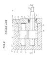
- Figs. 8 to 11 show the fluid-pressure apparatus disclosed in the Unexamined Patent Application (Translation of PCT Application) Publication No. 2010-521610 , specifically, an oil hydraulic device. It is noted that, although the Unexamined Patent Application (Translation of PCT Application) Publication No. 2010-521610 does not disclose the whole configuration of the oil hydraulic device, Figs. 8 and 9 shows also the whole configuration thereof.
- an oil hydraulic device 1 has a housing 2 having a hydraulic chamber 4 formed therein, a pair of helical gears 20', 23' (hereinafter, simply referred to as "gears") inserted in the hydraulic chamber 4 in a state where their tooth portions mesh with each other, and bushes 30, 32 as two support members which are inserted in the hydraulic chamber 4 in a state of being in contact with both end surfaces of the pair of gears 20', 23' to support the pair of gears 20', 23'.
- gears a pair of helical gears 20', 23'
- the housing 2 comprises a body 3 in which the hydraulic chamber 4 having a space with a substantially 8-shaped cross-section is formed from one end surface to the other end surface thereof, a first flange 8 screwed on the one end surface of the body 3, and a second flange 11 similarly screwed on the other end surface of the body 3, and the hydraulic chamber 4 is closed by the first flange 8 and the second flange 11.
- One of the pair of gears 20', 23' is a driving gear 20' and the other is a driven gear 23'.
- the gears 20', 23' respectively have rotating shafts 21, 24 which are respectively provided to extend in the axial directions of the gears 20', 23' from both end surfaces of the gears 20', 23', and the rotating shaft 21 of the gear 20' has a tapered portion formed on one end portion thereof and a screw portion 22 is formed on the tip of the tapered portion.
- the pair of gears 20', 23' are, as described above, contained in the hydraulic chamber 4 in a state of meshing with each other, and the outer surfaces of their tooth tips are in sliding contact with an inner peripheral surface 7 of the hydraulic chamber 4.
- the bushes 30, 32 are metal bearings comprising a plate-shaped member having a substantially 8-shaped cross-section and respectively have two support holes 31, 33, and the rotating shafts 21, 24 of the gears 20', 23' are inserted through the support holes 31, 33, and thereby the rotating shafts 21, 24 are supported to be rotatable. Further, the bushes 30, 32 are inserted in the hydraulic chamber 4 in a state where the rotating shafts 21, 24 of the gears 20', 23' are inserted through the support holes 31, 33 and end surfaces of the bushes 30, 32 are in contact with the end surfaces of the gears 20', 23'.
- the first flange 8 has an insertion hole 9 formed through which the rotating shaft 21 having the screw portion 22 of the driving gear 20' is inserted, and the driving gear 20' is arranged in the hydraulic chamber 4 in a state where the rotating shaft 21 is inserted through the insertion hole 9 of the first flange 8 and extended to the outside.
- an oil seal 10 is provided in the insertion hole 9 and the oil seal 10 provides sealing between the insertion hole 9 and the rotating shaft 21.
- O-rings 12 are respectively interposed between the end surfaces of the body 3 and the first and second flanges 8, 11, and the O-rings 12 provide sealing therebetween.
- the body 3 has an intake port (intake flow path) 5, which leads to the hydraulic chamber 4, bored in one side surface thereof and a discharge port (discharge flow path) 6, which similarly leads to the hydraulic chamber 4, bored in another side surface thereof located opposite said side surface with the hydraulic chamber 4 between them.
- intake port 5 and the discharge port 6 are provided so that their axes are positioned at the middle between the rotating shafts 21, 24 of the pair of gears 20', 23'.
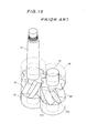
- the pair of gears 20', 23' has such a theoretical tooth profile that their tooth surfaces are continuously and linearly in contact with each other in the axial direction of the rotating shafts 21, 24 and tooth tips of one of them are brought into contact with tooth bottoms of the other of them as shown in Figs. 10 and 11 .
- the hydraulic chamber 4 is divided in two, a high-pressure side and a low-pressure side, with the contact portion 26 as a border.
- the bushes 30, 32 being in contact with the end surfaces of the gears 20', 23' have a function of preventing leakage of the operation fluid from the high-pressure side to the low-pressure side by the contact between the gears 20' and 23', and therefore, in the oil hydraulic device 1, the roundness or inclination of edges of the end surfaces of the tooth portions of the gears 20', 23' is set to be as small as possible.
- the oil hydraulic device 1 having the above-described configuration can be used as an oil hydraulic pump or an oil hydraulic motor.
- appropriate piping which is connected to an appropriate tank for storing an operation fluid therein is connected to the intake port 5 of the housing 2, and the rotating shaft 21 of the driving gear 20' is driven by an appropriate drive motor, thereby rotating the driving gear 20' in the direction indicated by the arrow R shown in Fig. 11 .
- the oil hydraulic device 1 functions as an oil hydraulic pump.
- the edges have portions where the angle is acute (acute angle portions) 27a' and portions where the angle is obtuse (obtuse angle portions) 27b', and, of these portions, particularly the acute angle portions 27a' are easily damaged.
- Fig. 12 shows a state where edge portions are damaged as described above. It is noted that the damaged portions are indicated by the reference C.
- Figs. 13 and 15 are sectional views showing a state where the bush 30 (32) is in contact with the end surfaces of the gears 20', 23', and Fig. 13 shows a case where the edges are not broken and Fig. 15 shows a case where an edge portion is broken.
- Fig. 14 is a sectional view showing a portion where the gear 20' (23') is in contact with the bush 30 (32) and the inner peripheral surface 7 of the body 3, and shows a case where the edge is not broken.
- the above-described conventional oil hydraulic device 1 has a structural problem that a rated discharge amount cannot be maintained for a long time, and a problem that the device lacks reliability.
- the present invention has been achieved in view of the above-described circumstances and an object thereof is to provide a conventional fluid-pressure apparatus which is quiet and has high output efficiency, the apparatus being capable of maintaining the quietness and the output efficiency for a long time, and having higher reliability than before.
- the present invention for solving the above-described problems, relates to a fluid-pressure apparatus comprising:
- At least the intermediate parts between the tooth tips and tooth bottoms are chamfered and the roundness or inclination of the intermediate parts is larger than those of the tooth tips and the tooth bottoms.
- the edge strength of the intermediate parts can be increased, thereby preventing the intermediate parts from being damaged due to contact stress generated when the pair of gears mesh with each other.
- a larger stress acts on the intermediate parts, particularly a power transmitting region, than on other portions, increasing the strength thereof by chamfering makes it possible to improve the durability thereof.
- the tooth tips and the tooth bottoms are not a power transmitting region and the stress acting thereon is not so large, even if the roundness or inclination of their edge portions is made small, there is not a fear that they are damaged.
- the roundness or inclination of the edges of the tooth potions causes mutually contradictory phenomena that, when it is small, although the sealablity is improved, the strength is reduced and the edges are easily damaged, and that, on the other hand, when it is large, although the strength is increased and the edges are hardly damaged, the sealability is reduced and leakage easily occurs.
- the original performance of being quiet and having high output efficiency can be maintained for a long time and higher reliability than before can be obtained.
- edge portions corresponding to the power transmitting region are chamfered.
- power-transmitting-region portions since particularly large stress acts on the power-transmitting-region portions, chamfering the portions can prevent damage thereof.
- the "power-transmitting-region portion” means a theoretical curve portion which is represented by theoretical curves used in general gears, such as an involute curve and a trochoid curve, specifically a theoretical curve portion which is arranged in the vicinity of a pitch point of the gears and cannot be expressed by one perfect circle (single R).
- the power-transmitting-region portion is generally positioned in a range of 0.1 h to 0.9h from the tooth bottom, where h is the tooth depth of the gears. Further, in the present invention, it is particularly preferable that the intermediate part is positioned in a range of 0.26h to 0.81 h from the tooth bottom.
- the pair of gears may be helical gears, and in this case, the chamfering may be performed on only the intermediate parts on a side where the angle between the end surface of the gear and the tooth surface is acute.
- the strength of the acute-angle edge portions is lower than that of the obtuse-angle edge portions, and, although there is no fear of damage to the obtuse-angle edge portions, risk of damage to the acute-angle edge portions is high. Therefore, by chamfering the acute-angle edge portions, risk of damage can be reduced for the entire edges. Further, by suppressing the part to be chamfered to minimum, the sealability between the edges and the support members can be maintained more appropriately.
- the width of chamfering performed on the intermediate parts is between 0.05 and 0.8 mm, and it is more preferable that it is between 0.1 and 0.2 mm.
- the "depth of chamfering" here means, in a case where the chamfering is round, the chord length dimension of the arc portion, and means, in a case where the chamfering is a inclination, the width of the inclination.
- the fluid-pressure apparatus of the present invention since, on the edges of the end surfaces of the tooth portions of the gears, at least the intermediate parts between the tooth tips and the tooth bottoms are chamfered and the roundness or inclination of the intermediate parts is made larger than those of the tooth tips and the tooth bottoms, it is possible to prevent the edges from being damaged due to contact force generated when the pair of gears mesh with each other, and it is possible to prevent leakage of the operation fluid through between the gears and the support members. Thereby, the original performance of being quiet and having high output efficiency can be maintained for a long time and higher reliability than before can be obtained.
- an oil hydraulic device using a hydraulic oil as operation fluid will be described with reference to Figs. 1 to 7 .
- the oil hydraulic device according to this embodiment has, instead of the pair of helical gears 20', 23' of the conventional oil hydraulic device 1 shown in Figs. 8 to 11 , a similar pair of helical gears 20, 23 edges of end surfaces of which are chamfered, and, other than that, the configuration thereof is the same as that of the conventional oil hydraulic device 1. Therefore, detailed explanation of the same components as those of the conventional oil hydraulic device 1 is omitted.
- Fig. 2 is a schematic diagram for explaining a method of determining the width of chamfering of an edge portion of an end surface of the gears 20, 23. It is noted that h in Fig. 2 indicates the tooth depth of the tooth portion.
- the tooth bottom part is chamfered so that the width of chamfering is gradually increased from 0 to the maximum width of chamfering starting from the tooth bottom to h1
- the intermediate part is chamfered so that the width of chamfering of the entire part is the maximum width of chamfering
- the tooth tip part is chamfered so that the width of chamfering is gradually decreased from the maximum width of chamfering to 0 starting from h2 to the tooth tip.
- the values of h1 and h2 are set so that the power-transmitting-region portion is included between h1 and h2, and h1 is from 0.1 h to 0.5h (positioned at 10 to 50 % of the tooth depth from the tooth bottom) and h2 is from 0.5h to 0.9h (portioned at 50 to 90 % of the tooth depth from the tooth bottom).
- the widths of chamfering of the tooth tip part and the tooth bottom part are 0, in actual machining, it is very difficult to set the width of chamfering to 0. Therefore, it is allowed to make the tooth tip part and the tooth bottom part have such a width of chamfering that an acceptable degree of leakage from the high-pressure side to the low-pressure side occurs.
- the width of chamfering of the intermediate part does not have to be uniform and may be gradually changed. In brief, it is important to make the intermediate part have such a width of chamfering that the intermediate part can obtain a predetermined strength. In this sense, it is preferable that the width of chamfering of the intermediate part is from 0.05 to 0.8 mm, and it is more preferable that it is from 0.1 to 0.2 mm.
- the widths of chamfering of the tooth tip part and the tooth bottom part are set to 0 or such a width of chamfering that leakage from the high-pressure side to the low-pressure side is within an acceptable range, similarly to the conventional oil hydraulic device 1, it is possible to secure high sealability between the end surfaces of the gears 20, 23 and the end surfaces of the bushes 30, 32, and it is possible to secure high output efficiency.
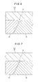
- Fig. 4 is a sectional view of a portion where a tooth tip part and a tooth bottom part of the gears 20, 23 mesh with each other
- Fig. 6 is a sectional view of a portion where the intermediate parts of the gears 20, 23 mesh with each other.
- Fig. 5 is a sectional view of a portion where the gear 20 (23) is in contact with the body 3 and the bush 30 (32).
- the widths of chamfering of the tooth tip part and the tooth bottom part on which high stress does not act are set to 0 or set to such a width of chamfering that leakage from the high-pressure side to the low-pressure side is within an acceptable range. Therefore, as seen from Figs. 13 and 14 , at the tooth tip parts and the tooth bottom parts, a gap between the gears 20, 23 and the bush 30 (32) and a gap between the gear 20 (23), the body 3 and the bush 30 (32) are very small, and, even if the leakage occurs, it can be suppressed within an acceptable range.
- Fig. 7 is a sectional view of a portion where the intermediate parts mesh with each other in a case where chamfering is performed on only the intermediate parts of the acute angle portions 27.
- Fig. 3 is a table which indicates the results obtained when the above-mentioned oil hydraulic pumps were driven and the discharge flow rates thereof were measured at a predetermined time interval.
- the oil hydraulic pumps of the Example, the Comparative Example 1 and the Comparative Example 2 have the same theoretical discharge flow rate.
- the initial discharge flow rate measured was 107.4 L/min (94 % of the theoretical value), and, the discharge flow rate measured after 200 hours had elapsed was almost the same, that is, 107 L/min.
- the initial discharge flow rate is 94 % of the theoretical value, and therefore it has a high discharge flow rate (that is, high volume efficiency) equivalent to that of the conventional oil hydraulic device 1 (the Comparative Example 1). This means that volume efficiency is not affected even when the intermediate parts are chamfered.
- the discharge flow rate was not changed so much even after the operation time has elapsed. This indicates that, since chamfering the edges of the tooth portions increases the strength of the edges and therefore the edges are hardly damaged, the seability between the end surfaces of the gears and the end surfaces of the bushes is preferably maintained even after the operation time has elapsed.
- the oil hydraulic device according to the present embodiment has the same configuration as that of the conventional oil hydraulic device 1 shown in Figs. 8 to 11 , a specific mode in which the present invention can be realized is not limited thereto.
- the fluid-pressure apparatus according to the present invention was embodied as an oil hydraulic pump as an example, it is not limited thereto and may be an oil hydraulic motor, for example.
- the operation fluid is not limited to the hydraulic oil, and coolant may be used as operation fluid, for example.
- the fluid-pressure apparatus according to the present invention is embodied as a coolant pump.
- the oil hydraulic device of the above embodiment has the configuration in which a pair of helical gears are used, the configuration thereof is not limited thereto and the oli hydraulic device may have a configuration in which a pair of spur gears are used. In this case, one or both of the edges of the end surfaces of the tooth portions can be chamfered.
- the oil hydraulic device of the above embodiment has the configuration in which the buses 30, 32 are directly in contact with the gears 20, 23, it may have a configuration in which plate-shaped sliding members (for example, side plates) are respectively interposed between the bushes 30, 32 and the gears 20, 23. Furthermore, each of the bushes 30, 32 may be divided in two and both sides of the rotating shafts 21, 24 may be individually supported by the four bushes.
- a configuration may be employed in which a key groove is formed in the tapered portion of the rotating shaft 21 and a key is inserted in the key groove, and an appropriate rotary body is coupled to the tapered portion of the rotating shaft 21 by the key groove and the key.
- the intake port 5 and the discharge port 6 are bored as through holes in the body, the intake hole 5 and the discharge hole 6 may be anything as long as they lead to the hydraulic chamber 4. Therefore, the intake port 5 and the discharge port 6 may be formed in the body, the first flange 8 and/or the second flange 11 to form flow paths (an intake flow path and a discharge flow path) one ends of which lead to the hydraulic chamber 4 though an opening formed in the body 3 and the other ends of which lead to the outside through an opening formed in the first flange 8 and/or the second flange 11.
- flow paths an intake flow path and a discharge flow path
Landscapes
- Engineering & Computer Science (AREA)
- Mechanical Engineering (AREA)
- General Engineering & Computer Science (AREA)
- Chemical & Material Sciences (AREA)
- Combustion & Propulsion (AREA)
- Rotary Pumps (AREA)
- Hydraulic Motors (AREA)
- Details And Applications Of Rotary Liquid Pumps (AREA)
Abstract
Description
- 0001 The present invention relates to a fluid-pressure apparatus having a pair of gears whose tooth surfaces mesh with each other.
- 0002 As a fluid-pressure apparatus as mentioned above, a hydraulic pump which rotates a pair of gears by an appropriate drive motor and pressurizes an operation fluid by the rotational motions of the gears and discharges the pressurized operation fluid, and a hydraulic motor which rotates gears by introducing a previously pressurized operation fluid therein and uses rotational forces of rotating shafts of the gears as a power are conventionally known.
- 0003 Such fluid-pressure apparatuses have a problem of operational noise generated by meshing of gears, a problem of noise generated by discontinuous change of the volume of the liquid confined between tooth surfaces of the meshing gears, and the like. In order to reduced such noise, conventionally a fluid-pressure apparatus using a pair of gears having a theoretical tooth profile which prevents the occurrence of a gap between tooth surfaces of the gears meshing with each other has been suggested (see the Unexamined Patent Application (Translation of PCT Application) Publication No.
2010-521610 - 0004
Figs. 8 to 11 show the fluid-pressure apparatus disclosed in the Unexamined Patent Application (Translation of PCT Application) Publication No.2010-521610 2010-521610 Figs. 8 and9 shows also the whole configuration thereof. - 0005 As shown in
Figs. 8 and9 , an oilhydraulic device 1 has ahousing 2 having a hydraulic chamber 4 formed therein, a pair of helical gears 20', 23' (hereinafter, simply referred to as "gears") inserted in the hydraulic chamber 4 in a state where their tooth portions mesh with each other, andbushes - 0006 The
housing 2 comprises abody 3 in which the hydraulic chamber 4 having a space with a substantially 8-shaped cross-section is formed from one end surface to the other end surface thereof, afirst flange 8 screwed on the one end surface of thebody 3, and asecond flange 11 similarly screwed on the other end surface of thebody 3, and the hydraulic chamber 4 is closed by thefirst flange 8 and thesecond flange 11. - 0007 One of the pair of gears 20', 23' is a driving gear 20' and the other is a driven gear 23'. The gears 20', 23' respectively have rotating
shafts shaft 21 of the gear 20' has a tapered portion formed on one end portion thereof and ascrew portion 22 is formed on the tip of the tapered portion. Further, the pair of gears 20', 23' are, as described above, contained in the hydraulic chamber 4 in a state of meshing with each other, and the outer surfaces of their tooth tips are in sliding contact with an innerperipheral surface 7 of the hydraulic chamber 4. - 0008 The
bushes support holes shafts support holes shafts bushes rotating shafts support holes bushes bushes first flange 8 and thesecond flange 11, respectively, and thereby movement of the gears 20', 23' and thebushes - 0009 Further, the
first flange 8 has aninsertion hole 9 formed through which therotating shaft 21 having thescrew portion 22 of the driving gear 20' is inserted, and the driving gear 20' is arranged in the hydraulic chamber 4 in a state where the rotatingshaft 21 is inserted through theinsertion hole 9 of thefirst flange 8 and extended to the outside. Further, anoil seal 10 is provided in theinsertion hole 9 and theoil seal 10 provides sealing between theinsertion hole 9 and the rotatingshaft 21. It is noted that O-rings 12 are respectively interposed between the end surfaces of thebody 3 and the first andsecond flanges rings 12 provide sealing therebetween. - 0010 Further, the
body 3 has an intake port (intake flow path) 5, which leads to the hydraulic chamber 4, bored in one side surface thereof and a discharge port (discharge flow path) 6, which similarly leads to the hydraulic chamber 4, bored in another side surface thereof located opposite said side surface with the hydraulic chamber 4 between them. Further, theintake port 5 and thedischarge port 6 are provided so that their axes are positioned at the middle between the rotatingshafts - 0011 The pair of gears 20', 23' has such a theoretical tooth profile that their tooth surfaces are continuously and linearly in contact with each other in the axial direction of the rotating
shafts Figs. 10 and11 . Thus, due to the contact between the gears 20' and 23', the hydraulic chamber 4 is divided in two, a high-pressure side and a low-pressure side, with thecontact portion 26 as a border. Thebushes hydraulic device 1, the roundness or inclination of edges of the end surfaces of the tooth portions of the gears 20', 23' is set to be as small as possible. - 0012 The oil
hydraulic device 1 having the above-described configuration can be used as an oil hydraulic pump or an oil hydraulic motor. For example, in a case where it is used as an oil hydraulic pump, appropriate piping which is connected to an appropriate tank for storing an operation fluid therein is connected to theintake port 5 of thehousing 2, and the rotatingshaft 21 of the driving gear 20' is driven by an appropriate drive motor, thereby rotating the driving gear 20' in the direction indicated by the arrow R shown inFig. 11 . - 0013 Thereby, the driven gear 23' meshing with the driving gear 20' is rotated in the direction indicated by the arrow R', the operation fluid in a
space 28 between the innerperipheral surface 7 of the hydraulic chamber 4 and the tooth portions of the gears 20', 23' is transferred to thedischarge port 6 side by the rotation of the gears 20', 23', and thedischarge port 6 side is brought into a high pressure and theintake port 5 side is brought into a low pressure, with thecontact portion 26 between the pair of gears 20', 23' as a border. - 0014 When the
intake port 5 side is brought into a negative pressure in the above-described manner, the operation fluid in the tank is inhaled into the low-pressure side of the hydraulic chamber 4 through the piping and theintake port 5, and is transferred to thedischarge port 6 side by the operation of the pair of gears 20', 23' and thereby pressurized to a high pressure, and the pressurized operation fluid is discharged through thedischarge port 6. - 0015 In the above-described manner, the oil
hydraulic device 1 functions as an oil hydraulic pump. - 0016 Further, according to this oil
hydraulic device 1, since, as described above, the pair of gears 20', 23' have such a theoretical tooth profile that their tooth surfaces are continuously and linearly in contact with each other in the axial direction of therotating shafts pressure discharge port 6 side to the low-pressure intake port 5 side, high discharge volume (which is volume efficiency and also output efficiency) can be obtained. - 0017
- Patent document 1: Japanese Unexamined Patent Application (Translation of PCT Application) Publication No.
2010-521610 - 0018 However, while the above-described conventional oil
hydraulic device 1 has, as described above, a merit that the noise problems can be solved and high volume efficiency can be obtained, it has a problem that, since the roundness or inclination of the edges of the end surfaces of the tooth portions is set to be as small as possible for obtaining high volume efficiency, when the pair of gears 20', 23' mesh with each other, contact stress tends to concentrate at the edges and the edges are easily damaged due to the contact stress. Particularly, intermediate parts between the teeth tips and the tooth bottoms are regions having a function of transmitting power from the driving gear 20' to the driven gear 23', and because a larger stress acts thereon than on the tooth tips and the tooth bottoms, the intermediate parts are easily damaged. Further, in a case where the pair of gears 20', 23' are helical gears like the oilhydraulic device 1, as shown inFig. 10 , the edges have portions where the angle is acute (acute angle portions) 27a' and portions where the angle is obtuse (obtuse angle portions) 27b', and, of these portions, particularly theacute angle portions 27a' are easily damaged.Fig. 12 shows a state where edge portions are damaged as described above. It is noted that the damaged portions are indicated by the reference C. - 0019 Further, if, for example, an edge portion is broken as described above, a problem that a broken piece caused by the breaking bites the pair of gears 20', 23' meshing with each other and the tooth surfaces thereof at the biting portion is damaged, that is, the damaged region is expanded is caused, and, in turn, a large abnormal noise occurs or the oil
hydraulic device 1 can be brought into a disabled state. Furthermore, it is conceivable that the broken piece caused by the breaking is transferred from the oilhydraulic device 1 to an oil hydraulic equipment connected thereto and the oil hydraulic equipment is damaged by the broken piece. - 0020 Further, in a case where an edge portion is broken, the sealability between the edges and the
bushes Figs. 13 to 15 . It is noted thatFigs. 13 and15 are sectional views showing a state where the bush 30 (32) is in contact with the end surfaces of the gears 20', 23', andFig. 13 shows a case where the edges are not broken andFig. 15 shows a case where an edge portion is broken. Further,Fig. 14 is a sectional view showing a portion where the gear 20' (23') is in contact with the bush 30 (32) and the innerperipheral surface 7 of thebody 3, and shows a case where the edge is not broken. - 0021 As shown in
Figs. 13 and 14 , in the case where the edges are not broken, since the roundness or inclination of the edges is set to be as small as possible, agap 40 between the edges of the gears 20', 23' and the bush 30 (32) and agap 41 between the edge portion of the gear 20' (23'), thebody 3 and the bush 30 (32) is very small, and further viscous resistance acts between the edges of the gears 20', 23', the bush 30 (32) and thebody 3. Therefore, leakage of the operation fluid through thegaps - 0022 On the other hand, if, for example, an edge portion of the gear 20' is broken as shown in
Fig. 15 , a gap 40' between the edges of the gears 20', 23' and the bush 30 (32) is large, and, as for the operation fluid in the vicinity of the edges and thebush 30, viscous resistance acts between the operation fluid and the edges and between the operation fluid and thebush 30, whereas, as for the operation fluid away from the edge portions and thebush 30, such viscous resistance does not act. Therefore, movement of the operation fluid through the gap 40' easily occurs and leakage of the operation fluid from the high-pressure side to the low-pressure side occurs. - 0023 Thus, the above-described conventional oil
hydraulic device 1 has a structural problem that a rated discharge amount cannot be maintained for a long time, and a problem that the device lacks reliability. - 0024 The present invention has been achieved in view of the above-described circumstances and an object thereof is to provide a conventional fluid-pressure apparatus which is quiet and has high output efficiency, the apparatus being capable of maintaining the quietness and the output efficiency for a long time, and having higher reliability than before.
- 0025 The present invention, for solving the above-described problems, relates to a fluid-pressure apparatus comprising:
- a pair of gears which each have a tooth portion formed at an outer peripheral portion thereof and the tooth portions of which mesh with each other;
- a housing which has a hydraulic chamber in which the pair of gears are contained in a state of meshing with each other, the hydraulic chamber having an arc-shaped inner peripheral surface with which outer surfaces of tooth tips of the pair of gears are in sliding contact;
- support members which are inserted in the hydraulic chamber of the housing in a state of being respectively in contact with both end surfaces of the gears and support rotating shafts respectively provided to extend outward from both end surfaces of the gears;
- the housing having an intake flow path and a discharge flow path which respectively open in one side inner surface and another side inner surface of the hydraulic chamber with the pair of gears between them; and
- the pair of gears having such a theoretical tooth profile that their tooth surfaces are continuously and linearly in contact with each other in an axial direction of the rotating shafts and the tooth tips of one of the gears are brought into contact with tooth bottoms of the other of the gears, wherein
- on edges of the end surfaces of the tooth portions of the gears, at least intermediate parts between the tooth tips and the tooth bottoms are chamfered and the intermediate parts have a roundness or inclination larger than those of the tooth tips and the tooth bottoms.
- 0026 According to the present invention, on the edges of the end surfaces of the tooth portions of the pair of gears, at least the intermediate parts between the tooth tips and tooth bottoms are chamfered and the roundness or inclination of the intermediate parts is larger than those of the tooth tips and the tooth bottoms.
- 0027 Thus, by chamfering at least the intermediate parts between the tooth tips and the tooth bottoms, the edge strength of the intermediate parts can be increased, thereby preventing the intermediate parts from being damaged due to contact stress generated when the pair of gears mesh with each other. Although a larger stress acts on the intermediate parts, particularly a power transmitting region, than on other portions, increasing the strength thereof by chamfering makes it possible to improve the durability thereof. On the other hand, because the tooth tips and the tooth bottoms are not a power transmitting region and the stress acting thereon is not so large, even if the roundness or inclination of their edge portions is made small, there is not a fear that they are damaged.
- 0028 Further, in the present invention, by making the roundness or inclination of the tooth tips and the tooth bottoms smaller than that of the intermediate parts, the sealability between the end surfaces of the gears and the support members is maintained.
- 0029 That is, although, if the entire edges of the tooth portions are uniformly chamfered to prevent the occurrence of damage of the edges, leakage from the high-pressure side to the low-pressure side occurs similarly to the above-described case where an edge portion is broken, such leakage can be prevented by making at least the tooth tips and the tooth bottoms have such a roundness or slop that the leakage does not occur.
- 0030 As described above, the roundness or inclination of the edges of the tooth potions causes mutually contradictory phenomena that, when it is small, although the sealablity is improved, the strength is reduced and the edges are easily damaged, and that, on the other hand, when it is large, although the strength is increased and the edges are hardly damaged, the sealability is reduced and leakage easily occurs.
- 0031 The inventor of the present application, as a result of eager studies, found out that it is possible to achieve both the sealabily and the strength by making the tooth tips and the tooth bottoms have a very small roundness or inclination which does not cause the leakage and making the intermediate parts have a roundness or slop which does not cause the damage.
- 0032 Further, according to the present invention, it is possible to provide a lubricating effect between the end surfaces of the gears and the support members by chamfering the intermediate parts.
- 0033 As described above, according to the fluid-pressure apparatus of the present invention, the original performance of being quiet and having high output efficiency can be maintained for a long time and higher reliability than before can be obtained.
- 0034 Further, in the present invention, it is particularly preferable that edge portions corresponding to the power transmitting region (hereinafter, referred to as "power-transmitting-region portions") are chamfered. As described above, since particularly large stress acts on the power-transmitting-region portions, chamfering the portions can prevent damage thereof.
- 0035 It is noted that the "power-transmitting-region portion" means a theoretical curve portion which is represented by theoretical curves used in general gears, such as an involute curve and a trochoid curve, specifically a theoretical curve portion which is arranged in the vicinity of a pitch point of the gears and cannot be expressed by one perfect circle (single R). The power-transmitting-region portion is generally positioned in a range of 0.1 h to 0.9h from the tooth bottom, where h is the tooth depth of the gears. Further, in the present invention, it is particularly preferable that the intermediate part is positioned in a range of 0.26h to 0.81 h from the tooth bottom.
- 0036 Further, in the present invention, the pair of gears may be helical gears, and in this case, the chamfering may be performed on only the intermediate parts on a side where the angle between the end surface of the gear and the tooth surface is acute.
- 0037 The strength of the acute-angle edge portions is lower than that of the obtuse-angle edge portions, and, although there is no fear of damage to the obtuse-angle edge portions, risk of damage to the acute-angle edge portions is high. Therefore, by chamfering the acute-angle edge portions, risk of damage can be reduced for the entire edges. Further, by suppressing the part to be chamfered to minimum, the sealability between the edges and the support members can be maintained more appropriately.
- 0038 Further, in the present invention, it is preferable that the width of chamfering performed on the intermediate parts is between 0.05 and 0.8 mm, and it is more preferable that it is between 0.1 and 0.2 mm. It is noted that the "depth of chamfering" here means, in a case where the chamfering is round, the chord length dimension of the arc portion, and means, in a case where the chamfering is a inclination, the width of the inclination.
- 0039 As described in detail above, according to the fluid-pressure apparatus of the present invention, since, on the edges of the end surfaces of the tooth portions of the gears, at least the intermediate parts between the tooth tips and the tooth bottoms are chamfered and the roundness or inclination of the intermediate parts is made larger than those of the tooth tips and the tooth bottoms, it is possible to prevent the edges from being damaged due to contact force generated when the pair of gears mesh with each other, and it is possible to prevent leakage of the operation fluid through between the gears and the support members. Thereby, the original performance of being quiet and having high output efficiency can be maintained for a long time and higher reliability than before can be obtained.
- 0040
-
Fig. 1 is a perspective view showing a state where edge portions of an end surface of a gear is chamfered; -
Fig. 2 is a schematic diagram for explaining a method of determining a width of chamfering of an edge portion of an end surface of a gear; -
Fig. 3 is a table indicating results of a performance degradation experiment of an oil hydraulic device; -
Fig. 4 is a sectional view of a contact portion between a pair of gears and a bush, for explaining an effect of the present invention; -
Fig. 5 is a sectional view of a contact portion between a gear, a bush and a body, for explaining the effect of the present invention; -
Fig. 6 is a sectional view of a contact portion between the pair of gears and the bush, for explaining the effect of the present invention; -
Fig. 7 is a sectional view of a contact portion between the pair of gears and the bush, for explaining the effect of the present invention; -
Fig. 8 is a sectional view showing a configuration a conventional oil hydraulic device; -
Fig. 9 is a sectional view taken along A-A inFig. 8 ; -
Fig. 10 is a perspective view showing a state where buses are in contact with end surfaces of a pair of gears meshing with each other; -
Fig. 11 is a plane view showing a state where helical gears mesh with each other; -
Fig. 12 is a perspective view showing a state where edge portions of an end surface and a tooth surface of a gear are broken; -
Fig. 13 is a sectional view of a contact portion between a pair of gears and a bush in the conventional oil hydraulic device; -
Fig. 14 is a sectional view of a contact portion between a gear, a bush and a body in the conventional oil hydraulic device; and -
Fig. 15 is a sectional view of a contact portion between a pair of gears and a bush, for explaining a problem in the conventional oil hydraulic device. Description of Embodiments - 0041 Hereinafter, in connection with a fluid-pressure apparatus according to a specific embodiment of the present invention, as an example, an oil hydraulic device using a hydraulic oil as operation fluid will be described with reference to
Figs. 1 to 7 . It is noted that the oil hydraulic device according to this embodiment has, instead of the pair of helical gears 20', 23' of the conventional oilhydraulic device 1 shown inFigs. 8 to 11 , a similar pair ofhelical gears hydraulic device 1. Therefore, detailed explanation of the same components as those of the conventional oilhydraulic device 1 is omitted. - 0042 In the pair of
helical gears gears acute angle portion 27a shown inFig. 2 , corresponding to theacute angle portion 27a' shown inFig. 10 ) are chamfered, and the width of chamfering is varied from the tooth tip to the tooth bottom and the width of chamfering of the intermediate part is larger than those of the tooth tip and the tooth bottom (seeFig. 1 ). This is specifically explained with reference toFig. 2 . It is noted that a chamfered portion is indicated by the reference M. - 0043
Fig. 2 is a schematic diagram for explaining a method of determining the width of chamfering of an edge portion of an end surface of thegears Fig. 2 indicates the tooth depth of the tooth portion. In a case where: the portion from the tooth bottom to h1 is defined as a tooth bottom part; the portion from h1 to h2 is defined as an intermediate part; the portion from h2 to the tooth tip is defined as a tooth tip part; and a predetermined maximum depth of chamfering is set, the tooth bottom part is chamfered so that the width of chamfering is gradually increased from 0 to the maximum width of chamfering starting from the tooth bottom to h1, the intermediate part is chamfered so that the width of chamfering of the entire part is the maximum width of chamfering, and the tooth tip part is chamfered so that the width of chamfering is gradually decreased from the maximum width of chamfering to 0 starting from h2 to the tooth tip. - 0044 Here, it is preferable that the values of h1 and h2 are set so that the power-transmitting-region portion is included between h1 and h2, and h1 is from 0.1 h to 0.5h (positioned at 10 to 50 % of the tooth depth from the tooth bottom) and h2 is from 0.5h to 0.9h (portioned at 50 to 90 % of the tooth depth from the tooth bottom). In other words, it is preferable that the intermediate part is set within a range of 0.1 h to 0.9h, and as a more preferable example, an example in which h1 = 0.26h and h2 = 0.81 h can be given.
- 0045 It is noted that, although, in the foregoing, the widths of chamfering of the tooth tip part and the tooth bottom part are 0, in actual machining, it is very difficult to set the width of chamfering to 0. Therefore, it is allowed to make the tooth tip part and the tooth bottom part have such a width of chamfering that an acceptable degree of leakage from the high-pressure side to the low-pressure side occurs.
- 0046 Further, the width of chamfering of the intermediate part does not have to be uniform and may be gradually changed. In brief, it is important to make the intermediate part have such a width of chamfering that the intermediate part can obtain a predetermined strength. In this sense, it is preferable that the width of chamfering of the intermediate part is from 0.05 to 0.8 mm, and it is more preferable that it is from 0.1 to 0.2 mm.
- 0047 In the oil hydraulic device of the present embodiment having the above-described configuration, since the width of chamfering of the intermediate parts of the acute angle portions 27 which are easily damaged when the
gears - 0048 On the other hand, since the widths of chamfering of the tooth tip part and the tooth bottom part are set to 0 or such a width of chamfering that leakage from the high-pressure side to the low-pressure side is within an acceptable range, similarly to the conventional oil
hydraulic device 1, it is possible to secure high sealability between the end surfaces of thegears bushes - 0049 That is, if the entire edges of the
gears Figs. 4 and6 ,large gaps gears gears gears gaps Fig. 5 , alarge gap 51 is generated between the gear 20 (23), thebody 3 and the bush 30 (32), and the operation fluid leaks through thegap 51. Therefore, in this case, while the strength of the edges can be increased, leakage of the operation fluid occurs on the entire edges and therefore there is a problem that high sealability cannot be secured. - 0050 It is noted that
Fig. 4 is a sectional view of a portion where a tooth tip part and a tooth bottom part of thegears Fig. 6 is a sectional view of a portion where the intermediate parts of thegears Fig. 5 is a sectional view of a portion where the gear 20 (23) is in contact with thebody 3 and the bush 30 (32). - 0051 To the contrary, in the oil hydraulic device according to the present embodiment, as described above, the widths of chamfering of the tooth tip part and the tooth bottom part on which high stress does not act are set to 0 or set to such a width of chamfering that leakage from the high-pressure side to the low-pressure side is within an acceptable range. Therefore, as seen from
Figs. 13 and 14 , at the tooth tip parts and the tooth bottom parts, a gap between thegears body 3 and the bush 30 (32) are very small, and, even if the leakage occurs, it can be suppressed within an acceptable range. - 0052 Further, since predetermined chamfering is performed on only the intermediate parts of the
acute angle portions 27a which are easily broken when thegears Fig. 7 , although agap 53 generated between thegears gap 52 shown inFig. 6 . Therefore, the amount of leakage is reduced for that. It is noted thatFig. 7 is a sectional view of a portion where the intermediate parts mesh with each other in a case where chamfering is performed on only the intermediate parts of the acute angle portions 27. - 0053 Thus, according to the oil hydraulic device of the present embodiment, for the above-described reasons, an effect that the durability is high and high output efficiency can be maintained for a long time as compared with the conventional oil
hydraulic device 1 is achieved. - 0054 In this connection, the inventor of the present application performed a performance comparison experiment using an oil hydraulic pump corresponding to the conventional oil
hydraulic device 1 using helical gears the edges of the tooth portions of which are not chamfered (Comparative Example 1), an oil hydraulic pump using helical gears the entire edges of the tooth portions of which are chamfered (Comparative Example 2) and an oil hydraulic pump using helical gears only the acute-angle edge portions of the tooth portions of which are chamfered so that the width of chamfering of the intermediate part between tooth tip part and the tooth bottom part is larger than those of the tooth tip part and the tooth bottom part (Example). The results thereof are described below. It is noted thatFig. 3 is a table which indicates the results obtained when the above-mentioned oil hydraulic pumps were driven and the discharge flow rates thereof were measured at a predetermined time interval. - 0055 As shown in
Fig. 3 , the oil hydraulic pumps of the Example, the Comparative Example 1 and the Comparative Example 2 have the same theoretical discharge flow rate. In the Example, the initial discharge flow rate measured was 107.4 L/min (94 % of the theoretical value), and, the discharge flow rate measured after 200 hours had elapsed was almost the same, that is, 107 L/min. On the other hand, in the Comparative Example 1, although the initial discharge flow rate measured was 109 L/min (95.4% of the theoretical value), thereafter, the discharge flow rate was reduced as time elapsed, and, after 200 hours had elapsed, the discharge flow rate was 103 L/min (90.1 % of the theoretical value) and the discharge flow rate has been reduced by 2.8 % as compared with the initial discharge flow rate. Further, in the Comparative Example 2, although the initial discharge flow rate was 95.5 L/min (83.6 % of the theoretical value), which was low as compared with the Example and the Comparative Example 1, the discharge flow rate thereof was not reduced with elapse of time like the Example and the discharge flow rate after 200 hours had elapsed was 94.5 L/min (82.7 % of the theoretical value). - 0056 As described above, in the oil hydraulic pump of the Example, the initial discharge flow rate is 94 % of the theoretical value, and therefore it has a high discharge flow rate (that is, high volume efficiency) equivalent to that of the conventional oil hydraulic device 1 (the Comparative Example 1). This means that volume efficiency is not affected even when the intermediate parts are chamfered.
- 0057 On the other hand, in the Comparative Example 2 in which the entire edges were chamfered, the obtained initial discharge flow rate was only 83.6 % of the theoretical value. This indicates that, when the tooth tip parts and the tooth bottom parts of the edge portions are chamfered, the leakage becomes extremely large and the volume efficiency thereof is remarkably lowered.
- 0058 Further, in the Example and the Comparative Example 2, the discharge flow rate was not changed so much even after the operation time has elapsed. This indicates that, since chamfering the edges of the tooth portions increases the strength of the edges and therefore the edges are hardly damaged, the seability between the end surfaces of the gears and the end surfaces of the bushes is preferably maintained even after the operation time has elapsed.
- 0059 On the other hand, in the Comparative Example 1 in which the edges were not chamfered, the discharge flow rate was reduced as time elapsed, and, after 200 hours have elapsed, the discharge flow rate has been reduced by 2.8 % as compared with the initial discharge flow rate. In a case where the edges are not chamfered, the edges are easily broken, and, in view of the foregoing, it is seen that the edges are broken with elapse of time, and thereby the sealability between the end surfaces of the gears and the end surfaces of the bushes is reduced and the leakage is increased.
- 0060 Thus, according to the oil hydraulic pump of the Example, it is possible to obtain high volume efficiency and maintain it for a long time.
- 0061 As described in detail above, in the oil hydraulic pump of the present embodiment, since only the acute-angle edge portions of the end surfaces of the tooth portions of the pair of helical gears are chamfered so that the intermediate parts thereof have a larger width of chamfering than those of the tooth tip parts and the tooth bottom parts, it is possible to increase the strength of the intermediate parts and prevent the intermediate parts from being broken. Further, such chamfering makes it possible to secure high volume efficiency equivalent to that of the conventional oil
hydraulic device 1 and maintain the high volume efficiency for a long time, thereby improving the durability as compared with the conventional oilhydraulic device 1 and obtaining high reliability. - 0062 It is noted that, although, as described above, except for the fact that the edges of the end surfaces of the pair of
helical gears hydraulic device 1 shown inFigs. 8 to 11 , a specific mode in which the present invention can be realized is not limited thereto. - 0063 For example, although, in the above embodiment, the fluid-pressure apparatus according to the present invention was embodied as an oil hydraulic pump as an example, it is not limited thereto and may be an oil hydraulic motor, for example. Further, the operation fluid is not limited to the hydraulic oil, and coolant may be used as operation fluid, for example. In this case, the fluid-pressure apparatus according to the present invention is embodied as a coolant pump.
- 0064 Further, the oil hydraulic device of the above embodiment has the configuration in which a pair of helical gears are used, the configuration thereof is not limited thereto and the oli hydraulic device may have a configuration in which a pair of spur gears are used. In this case, one or both of the edges of the end surfaces of the tooth portions can be chamfered.
- 0065 Further, although the oil hydraulic device of the above embodiment has the configuration in which the
buses gears bushes gears bushes rotating shafts - 0066 Further, a configuration may be employed in which a key groove is formed in the tapered portion of the
rotating shaft 21 and a key is inserted in the key groove, and an appropriate rotary body is coupled to the tapered portion of therotating shaft 21 by the key groove and the key. - 0067 Further, although, in the above embodiment, the
intake port 5 and thedischarge port 6 are bored as through holes in the body, theintake hole 5 and thedischarge hole 6 may be anything as long as they lead to the hydraulic chamber 4. Therefore, theintake port 5 and thedischarge port 6 may be formed in the body, thefirst flange 8 and/or thesecond flange 11 to form flow paths (an intake flow path and a discharge flow path) one ends of which lead to the hydraulic chamber 4 though an opening formed in thebody 3 and the other ends of which lead to the outside through an opening formed in thefirst flange 8 and/or thesecond flange 11. - 0068
- 1
- Oil hydraulic device
- 2
- Housing
- 4
- Hydraulic chamber
- 5
- Intake port
- 6
- Discharge port
- 20, 20', 23, 23'
- Helical gear
- 21, 24
- Rotating shaft
- 27a
- Acute angle portion
- 27b
- Obtuse angle portion
- 28
- Space
- 30, 32
- Bush
- 31, 33
- Support hole
Claims (10)
- A fluid-pressure apparatus comprising:a pair of gears which each have a tooth portion formed at an outer peripheral portion thereof and the tooth portions of which mesh with each other;a housing which has a hydraulic chamber in which the pair of gears are contained in a state of meshing with each other, the hydraulic chamber having an arc-shaped inner peripheral surface with which outer surfaces of tooth tips of the pair of gears are in sliding contact;support members which are inserted in the hydraulic chamber of the housing in a state of being respectively in contact with both end surfaces of the gears and support rotating shafts respectively provided to extend outward from both end surfaces of the gears;the housing having an intake flow path and a discharge flow path which respectively open in one side inner surface and another side inner surface of the hydraulic chamber with the pair of gears between them; andthe pair of gears having such a theoretical tooth profile that their tooth surfaces are continuously and linearly in contact with each other in an axial direction of the rotating shafts and the tooth tips of one of the gears are brought into contact with tooth bottoms of the other of the gears, whereinon edges of the end surfaces of the tooth portions of the gears, chamfering is performed on at least intermediate parts between the tooth tips and the tooth bottoms and the intermediate parts have a roundness or inclination larger than those of the tooth tips and the tooth bottoms.
- The fluid-pressure apparatus according to claim 1, wherein
the pair of gears are helical gears, and
the chamfering is performed on only the intermediate parts positioned on a side where the angle between the end surface and the tooth surface is acute. - The fluid-pressure apparatus according to claim 1, wherein the intermediate parts are a power-transmitting region portion of the gears.
- The fluid-pressure apparatus according to claim 3, wherein
the pair of gears are helical gears, and
the chamfering is performed on only the intermediate parts positioned on a side where the angle between the end surface and the tooth surface is acute. - The fluid-pressure apparatus according to claim 1, wherein the intermediate part is within a range of 0.1 h to 0.9h from the tooth bottom, where h is a tooth depth of the gears.
- The fluid-pressure apparatus according to claim 5, wherein
the pair of gears are helical gears, and
the chamfering is performed on only the intermediate parts positioned on a side where the angle between the end surface and the tooth surface is acute. - The fluid-pressure apparatus according to claim 1, wherein the intermediate part is within a range of 0.26h to 0.81 h from the tooth bottom, where h is a tooth depth of the gears.
- The fluid-pressure apparatus according to claim 7, wherein
the pair of gears are helical gears, and
the chamfering is performed on only the intermediate parts positioned on a side where the angle between the end surface and the tooth surface is acute. - The fluid-pressure apparatus according to any one of claims 1 to 8, wherein a width of the chamfering performed on the intermediate parts is from 0.05 to 0.8 mm.
- The fluid-pressure apparatus according to any one of claims 1 to 8, wherein a width of the chamfering performed on the intermediate parts is from 0.1 to 0.2 mm.
Applications Claiming Priority (2)
| Application Number | Priority Date | Filing Date | Title |
|---|---|---|---|
| JP2011266732A JP5993138B2 (en) | 2011-12-06 | 2011-12-06 | Hydraulic device |
| PCT/JP2012/070337 WO2013084542A1 (en) | 2011-12-06 | 2012-08-09 | Fluid-pressure apparatus |
Publications (3)
| Publication Number | Publication Date |
|---|---|
| EP2789854A1 true EP2789854A1 (en) | 2014-10-15 |
| EP2789854A4 EP2789854A4 (en) | 2015-08-19 |
| EP2789854B1 EP2789854B1 (en) | 2018-10-10 |
Family
ID=48573927
Family Applications (1)
| Application Number | Title | Priority Date | Filing Date |
|---|---|---|---|
| EP12855423.5A Not-in-force EP2789854B1 (en) | 2011-12-06 | 2012-08-09 | Fluid-pressure apparatus |
Country Status (5)
| Country | Link |
|---|---|
| US (1) | US9366137B2 (en) |
| EP (1) | EP2789854B1 (en) |
| JP (1) | JP5993138B2 (en) |
| CN (1) | CN103975162B (en) |
| WO (1) | WO2013084542A1 (en) |
Families Citing this family (4)
| Publication number | Priority date | Publication date | Assignee | Title |
|---|---|---|---|---|
| JP6446961B2 (en) * | 2014-09-30 | 2019-01-09 | ダイキン工業株式会社 | Gear pump or gear motor |
| DE102015214584B4 (en) * | 2015-07-31 | 2024-11-07 | Robert Bosch Gmbh | rotational/translational converter transmission |
| CN110748483B (en) * | 2019-08-20 | 2024-09-17 | 神钢无锡压缩机股份有限公司 | Screw compressor host computer structure of making an uproar falls |
| US11624360B2 (en) * | 2020-12-23 | 2023-04-11 | Hamilton Sundstrand Corporation | Gear pump with gear including etched surfaces |
Family Cites Families (13)
| Publication number | Priority date | Publication date | Assignee | Title |
|---|---|---|---|---|
| GB574364A (en) | 1943-06-09 | 1946-01-02 | Frank Robert Bell | Improvements in or relating to rotary pumps and engines of the gear-wheel type |
| JPS5170504A (en) * | 1974-12-14 | 1976-06-18 | Kayaba Industry Co Ltd | KOSOKUKO ATSUHAGURUMAHONPU |
| JPS51109401U (en) * | 1975-03-01 | 1976-09-03 | ||
| JPS5922465B2 (en) | 1975-03-20 | 1984-05-26 | 松下電器産業株式会社 | Flat armature with sandwich structure |
| DE2714705C3 (en) | 1977-04-01 | 1984-04-12 | Paul Dipl.-Ing. Bellach Truninger | Gear pump |
| US4548531A (en) * | 1983-05-03 | 1985-10-22 | United Technologies Corporation | Method for chamfering the edges of gear teeth |
| EP0211127B1 (en) | 1985-08-01 | 1991-02-06 | United Technologies Corporation | Method for chamfering the edges of gear teeth |
| WO1992009807A1 (en) * | 1990-11-30 | 1992-06-11 | Kabushiki Kaisha Maekawa Seisakusho | Fluid jetting type screw compressor |
| JP2003083259A (en) * | 2001-09-13 | 2003-03-19 | Koyo Seiko Co Ltd | Gear pump |
| SE520250C2 (en) * | 2002-08-14 | 2003-06-17 | Svenska Rotor Maskiner Ab | Screw rotor compressor, has rotor body with ears having chamfered region at trailing end of one flank |
| JP2008215382A (en) | 2007-02-28 | 2008-09-18 | Jtekt Corp | Helical gear, planetary gear mechanism including the same, and vehicle differential |
| ITBO20070172A1 (en) * | 2007-03-14 | 2008-09-15 | Mario Antonio Morselli | HYDRAULIC EQUIPMENT WITH REFINED GEARS |
| WO2009098773A1 (en) | 2008-02-08 | 2009-08-13 | Shimadzu Corporation | Gear wheel pump or motor |
-
2011
- 2011-12-06 JP JP2011266732A patent/JP5993138B2/en not_active Expired - Fee Related
-
2012
- 2012-08-09 WO PCT/JP2012/070337 patent/WO2013084542A1/en not_active Ceased
- 2012-08-09 US US14/361,589 patent/US9366137B2/en not_active Expired - Fee Related
- 2012-08-09 EP EP12855423.5A patent/EP2789854B1/en not_active Not-in-force
- 2012-08-09 CN CN201280059937.5A patent/CN103975162B/en not_active Expired - Fee Related
Also Published As
| Publication number | Publication date |
|---|---|
| CN103975162B (en) | 2016-11-23 |
| US20140322060A1 (en) | 2014-10-30 |
| EP2789854B1 (en) | 2018-10-10 |
| WO2013084542A1 (en) | 2013-06-13 |
| US9366137B2 (en) | 2016-06-14 |
| JP5993138B2 (en) | 2016-09-14 |
| JP2013119780A (en) | 2013-06-17 |
| CN103975162A (en) | 2014-08-06 |
| EP2789854A4 (en) | 2015-08-19 |
Similar Documents
| Publication | Publication Date | Title |
|---|---|---|
| EP2789854B1 (en) | Fluid-pressure apparatus | |
| JP5783305B2 (en) | Gear fluid device | |
| JPWO1992009807A1 (en) | Liquid injection screw compressor | |
| WO1992009807A1 (en) | Fluid jetting type screw compressor | |
| WO2011104891A1 (en) | Gear pump | |
| JP4917921B2 (en) | External gear pump with relief pocket | |
| JP6446961B2 (en) | Gear pump or gear motor | |
| CN216518614U (en) | Pump and vehicle | |
| EP1475536B1 (en) | Improved rotating pump | |
| JP6406281B2 (en) | Gear pump or gear motor | |
| CN113348303B (en) | Helical gear pump or motor | |
| JP6631106B2 (en) | Gear pump or gear motor | |
| JP6402862B2 (en) | Gear pump or gear motor | |
| JP2020122455A (en) | Geared pump or geared motor | |
| WO2016125263A1 (en) | Method for manufacturing hydraulic device, and hydraulic device manufactured using this manufacturing method | |
| JP2016020661A (en) | Pump device | |
| JP2017057726A (en) | Gear pump or gear motor | |
| US20040166010A1 (en) | Offset bearing for extended fuel pump life | |
| JP7014093B2 (en) | Gear pump or motor | |
| EP4545790A1 (en) | Gear pump or gear motor | |
| CN115875256A (en) | Pump and vehicle | |
| CN107420298A (en) | The impeller pump that a kind of internal rotor floats | |
| WO2024024035A1 (en) | External gear pump | |
| JP2022042820A (en) | Gear pump or gear motor | |
| JP2004176633A (en) | Gear pump |
Legal Events
| Date | Code | Title | Description |
|---|---|---|---|
| PUAI | Public reference made under article 153(3) epc to a published international application that has entered the european phase |
Free format text: ORIGINAL CODE: 0009012 |
|
| 17P | Request for examination filed |
Effective date: 20140612 |
|
| AK | Designated contracting states |
Kind code of ref document: A1 Designated state(s): AL AT BE BG CH CY CZ DE DK EE ES FI FR GB GR HR HU IE IS IT LI LT LU LV MC MK MT NL NO PL PT RO RS SE SI SK SM TR |
|
| DAX | Request for extension of the european patent (deleted) | ||
| RA4 | Supplementary search report drawn up and despatched (corrected) |
Effective date: 20150716 |
|
| RIC1 | Information provided on ipc code assigned before grant |
Ipc: F04C 14/28 20060101ALI20150710BHEP Ipc: F04C 2/18 20060101AFI20150710BHEP Ipc: F04C 2/08 20060101ALI20150710BHEP Ipc: F03C 2/08 20060101ALI20150710BHEP |
|
| GRAP | Despatch of communication of intention to grant a patent |
Free format text: ORIGINAL CODE: EPIDOSNIGR1 |
|
| STAA | Information on the status of an ep patent application or granted ep patent |
Free format text: STATUS: GRANT OF PATENT IS INTENDED |
|
| RIC1 | Information provided on ipc code assigned before grant |
Ipc: F04C 2/18 20060101AFI20180502BHEP Ipc: F04C 14/28 20060101ALI20180502BHEP Ipc: F03C 2/08 20060101ALI20180502BHEP Ipc: F04C 2/08 20060101ALI20180502BHEP |
|
| INTG | Intention to grant announced |
Effective date: 20180523 |
|
| GRAS | Grant fee paid |
Free format text: ORIGINAL CODE: EPIDOSNIGR3 |
|
| GRAA | (expected) grant |
Free format text: ORIGINAL CODE: 0009210 |
|
| STAA | Information on the status of an ep patent application or granted ep patent |
Free format text: STATUS: THE PATENT HAS BEEN GRANTED |
|
| AK | Designated contracting states |
Kind code of ref document: B1 Designated state(s): AL AT BE BG CH CY CZ DE DK EE ES FI FR GB GR HR HU IE IS IT LI LT LU LV MC MK MT NL NO PL PT RO RS SE SI SK SM TR |
|
| REG | Reference to a national code |
Ref country code: GB Ref legal event code: FG4D |
|
| REG | Reference to a national code |
Ref country code: CH Ref legal event code: EP Ref country code: AT Ref legal event code: REF Ref document number: 1051557 Country of ref document: AT Kind code of ref document: T Effective date: 20181015 |
|
| REG | Reference to a national code |
Ref country code: IE Ref legal event code: FG4D |
|
| REG | Reference to a national code |
Ref country code: DE Ref legal event code: R096 Ref document number: 602012052162 Country of ref document: DE |
|
| REG | Reference to a national code |
Ref country code: NL Ref legal event code: MP Effective date: 20181010 |
|
| REG | Reference to a national code |
Ref country code: LT Ref legal event code: MG4D |
|
| REG | Reference to a national code |
Ref country code: AT Ref legal event code: MK05 Ref document number: 1051557 Country of ref document: AT Kind code of ref document: T Effective date: 20181010 |
|
| PG25 | Lapsed in a contracting state [announced via postgrant information from national office to epo] |
Ref country code: NL Free format text: LAPSE BECAUSE OF FAILURE TO SUBMIT A TRANSLATION OF THE DESCRIPTION OR TO PAY THE FEE WITHIN THE PRESCRIBED TIME-LIMIT Effective date: 20181010 |
|
| PG25 | Lapsed in a contracting state [announced via postgrant information from national office to epo] |
Ref country code: FI Free format text: LAPSE BECAUSE OF FAILURE TO SUBMIT A TRANSLATION OF THE DESCRIPTION OR TO PAY THE FEE WITHIN THE PRESCRIBED TIME-LIMIT Effective date: 20181010 Ref country code: LV Free format text: LAPSE BECAUSE OF FAILURE TO SUBMIT A TRANSLATION OF THE DESCRIPTION OR TO PAY THE FEE WITHIN THE PRESCRIBED TIME-LIMIT Effective date: 20181010 Ref country code: HR Free format text: LAPSE BECAUSE OF FAILURE TO SUBMIT A TRANSLATION OF THE DESCRIPTION OR TO PAY THE FEE WITHIN THE PRESCRIBED TIME-LIMIT Effective date: 20181010 Ref country code: LT Free format text: LAPSE BECAUSE OF FAILURE TO SUBMIT A TRANSLATION OF THE DESCRIPTION OR TO PAY THE FEE WITHIN THE PRESCRIBED TIME-LIMIT Effective date: 20181010 Ref country code: BG Free format text: LAPSE BECAUSE OF FAILURE TO SUBMIT A TRANSLATION OF THE DESCRIPTION OR TO PAY THE FEE WITHIN THE PRESCRIBED TIME-LIMIT Effective date: 20190110 Ref country code: AT Free format text: LAPSE BECAUSE OF FAILURE TO SUBMIT A TRANSLATION OF THE DESCRIPTION OR TO PAY THE FEE WITHIN THE PRESCRIBED TIME-LIMIT Effective date: 20181010 Ref country code: PL Free format text: LAPSE BECAUSE OF FAILURE TO SUBMIT A TRANSLATION OF THE DESCRIPTION OR TO PAY THE FEE WITHIN THE PRESCRIBED TIME-LIMIT Effective date: 20181010 Ref country code: ES Free format text: LAPSE BECAUSE OF FAILURE TO SUBMIT A TRANSLATION OF THE DESCRIPTION OR TO PAY THE FEE WITHIN THE PRESCRIBED TIME-LIMIT Effective date: 20181010 Ref country code: NO Free format text: LAPSE BECAUSE OF FAILURE TO SUBMIT A TRANSLATION OF THE DESCRIPTION OR TO PAY THE FEE WITHIN THE PRESCRIBED TIME-LIMIT Effective date: 20190110 Ref country code: IS Free format text: LAPSE BECAUSE OF FAILURE TO SUBMIT A TRANSLATION OF THE DESCRIPTION OR TO PAY THE FEE WITHIN THE PRESCRIBED TIME-LIMIT Effective date: 20190210 |
|
| PG25 | Lapsed in a contracting state [announced via postgrant information from national office to epo] |
Ref country code: GR Free format text: LAPSE BECAUSE OF FAILURE TO SUBMIT A TRANSLATION OF THE DESCRIPTION OR TO PAY THE FEE WITHIN THE PRESCRIBED TIME-LIMIT Effective date: 20190111 Ref country code: PT Free format text: LAPSE BECAUSE OF FAILURE TO SUBMIT A TRANSLATION OF THE DESCRIPTION OR TO PAY THE FEE WITHIN THE PRESCRIBED TIME-LIMIT Effective date: 20190210 Ref country code: RS Free format text: LAPSE BECAUSE OF FAILURE TO SUBMIT A TRANSLATION OF THE DESCRIPTION OR TO PAY THE FEE WITHIN THE PRESCRIBED TIME-LIMIT Effective date: 20181010 Ref country code: SE Free format text: LAPSE BECAUSE OF FAILURE TO SUBMIT A TRANSLATION OF THE DESCRIPTION OR TO PAY THE FEE WITHIN THE PRESCRIBED TIME-LIMIT Effective date: 20181010 Ref country code: AL Free format text: LAPSE BECAUSE OF FAILURE TO SUBMIT A TRANSLATION OF THE DESCRIPTION OR TO PAY THE FEE WITHIN THE PRESCRIBED TIME-LIMIT Effective date: 20181010 |
|
| REG | Reference to a national code |
Ref country code: DE Ref legal event code: R097 Ref document number: 602012052162 Country of ref document: DE |
|
| PG25 | Lapsed in a contracting state [announced via postgrant information from national office to epo] |
Ref country code: CZ Free format text: LAPSE BECAUSE OF FAILURE TO SUBMIT A TRANSLATION OF THE DESCRIPTION OR TO PAY THE FEE WITHIN THE PRESCRIBED TIME-LIMIT Effective date: 20181010 Ref country code: DK Free format text: LAPSE BECAUSE OF FAILURE TO SUBMIT A TRANSLATION OF THE DESCRIPTION OR TO PAY THE FEE WITHIN THE PRESCRIBED TIME-LIMIT Effective date: 20181010 |
|
| PLBE | No opposition filed within time limit |
Free format text: ORIGINAL CODE: 0009261 |
|
| STAA | Information on the status of an ep patent application or granted ep patent |
Free format text: STATUS: NO OPPOSITION FILED WITHIN TIME LIMIT |
|
| PG25 | Lapsed in a contracting state [announced via postgrant information from national office to epo] |
Ref country code: SM Free format text: LAPSE BECAUSE OF FAILURE TO SUBMIT A TRANSLATION OF THE DESCRIPTION OR TO PAY THE FEE WITHIN THE PRESCRIBED TIME-LIMIT Effective date: 20181010 Ref country code: EE Free format text: LAPSE BECAUSE OF FAILURE TO SUBMIT A TRANSLATION OF THE DESCRIPTION OR TO PAY THE FEE WITHIN THE PRESCRIBED TIME-LIMIT Effective date: 20181010 Ref country code: SK Free format text: LAPSE BECAUSE OF FAILURE TO SUBMIT A TRANSLATION OF THE DESCRIPTION OR TO PAY THE FEE WITHIN THE PRESCRIBED TIME-LIMIT Effective date: 20181010 Ref country code: RO Free format text: LAPSE BECAUSE OF FAILURE TO SUBMIT A TRANSLATION OF THE DESCRIPTION OR TO PAY THE FEE WITHIN THE PRESCRIBED TIME-LIMIT Effective date: 20181010 |
|
| 26N | No opposition filed |
Effective date: 20190711 |
|
| PG25 | Lapsed in a contracting state [announced via postgrant information from national office to epo] |
Ref country code: SI Free format text: LAPSE BECAUSE OF FAILURE TO SUBMIT A TRANSLATION OF THE DESCRIPTION OR TO PAY THE FEE WITHIN THE PRESCRIBED TIME-LIMIT Effective date: 20181010 |
|
| PG25 | Lapsed in a contracting state [announced via postgrant information from national office to epo] |
Ref country code: TR Free format text: LAPSE BECAUSE OF FAILURE TO SUBMIT A TRANSLATION OF THE DESCRIPTION OR TO PAY THE FEE WITHIN THE PRESCRIBED TIME-LIMIT Effective date: 20181010 |
|
| GBPC | Gb: european patent ceased through non-payment of renewal fee |
Effective date: 20190809 |
|
| PG25 | Lapsed in a contracting state [announced via postgrant information from national office to epo] |
Ref country code: CH Free format text: LAPSE BECAUSE OF NON-PAYMENT OF DUE FEES Effective date: 20190831 Ref country code: LI Free format text: LAPSE BECAUSE OF NON-PAYMENT OF DUE FEES Effective date: 20190831 Ref country code: LU Free format text: LAPSE BECAUSE OF NON-PAYMENT OF DUE FEES Effective date: 20190809 Ref country code: MC Free format text: LAPSE BECAUSE OF FAILURE TO SUBMIT A TRANSLATION OF THE DESCRIPTION OR TO PAY THE FEE WITHIN THE PRESCRIBED TIME-LIMIT Effective date: 20181010 |
|
| REG | Reference to a national code |
Ref country code: BE Ref legal event code: MM Effective date: 20190831 |
|
| PG25 | Lapsed in a contracting state [announced via postgrant information from national office to epo] |
Ref country code: FR Free format text: LAPSE BECAUSE OF NON-PAYMENT OF DUE FEES Effective date: 20190831 Ref country code: IE Free format text: LAPSE BECAUSE OF NON-PAYMENT OF DUE FEES Effective date: 20190809 |
|
| PG25 | Lapsed in a contracting state [announced via postgrant information from national office to epo] |
Ref country code: GB Free format text: LAPSE BECAUSE OF NON-PAYMENT OF DUE FEES Effective date: 20190809 Ref country code: BE Free format text: LAPSE BECAUSE OF NON-PAYMENT OF DUE FEES Effective date: 20190831 |
|
| PG25 | Lapsed in a contracting state [announced via postgrant information from national office to epo] |
Ref country code: CY Free format text: LAPSE BECAUSE OF FAILURE TO SUBMIT A TRANSLATION OF THE DESCRIPTION OR TO PAY THE FEE WITHIN THE PRESCRIBED TIME-LIMIT Effective date: 20181010 |
|
| PG25 | Lapsed in a contracting state [announced via postgrant information from national office to epo] |
Ref country code: MT Free format text: LAPSE BECAUSE OF FAILURE TO SUBMIT A TRANSLATION OF THE DESCRIPTION OR TO PAY THE FEE WITHIN THE PRESCRIBED TIME-LIMIT Effective date: 20181010 Ref country code: HU Free format text: LAPSE BECAUSE OF FAILURE TO SUBMIT A TRANSLATION OF THE DESCRIPTION OR TO PAY THE FEE WITHIN THE PRESCRIBED TIME-LIMIT; INVALID AB INITIO Effective date: 20120809 |
|
| PGFP | Annual fee paid to national office [announced via postgrant information from national office to epo] |
Ref country code: IT Payment date: 20210830 Year of fee payment: 10 |
|
| PGFP | Annual fee paid to national office [announced via postgrant information from national office to epo] |
Ref country code: DE Payment date: 20210819 Year of fee payment: 10 |
|
| PG25 | Lapsed in a contracting state [announced via postgrant information from national office to epo] |
Ref country code: MK Free format text: LAPSE BECAUSE OF FAILURE TO SUBMIT A TRANSLATION OF THE DESCRIPTION OR TO PAY THE FEE WITHIN THE PRESCRIBED TIME-LIMIT Effective date: 20181010 |
|
| REG | Reference to a national code |
Ref country code: DE Ref legal event code: R119 Ref document number: 602012052162 Country of ref document: DE |
|
| PG25 | Lapsed in a contracting state [announced via postgrant information from national office to epo] |
Ref country code: IT Free format text: LAPSE BECAUSE OF NON-PAYMENT OF DUE FEES Effective date: 20220809 Ref country code: DE Free format text: LAPSE BECAUSE OF NON-PAYMENT OF DUE FEES Effective date: 20230301 |