EP2789850A1 - Floating type wind power generation device - Google Patents
Floating type wind power generation device Download PDFInfo
- Publication number
- EP2789850A1 EP2789850A1 EP12856460.6A EP12856460A EP2789850A1 EP 2789850 A1 EP2789850 A1 EP 2789850A1 EP 12856460 A EP12856460 A EP 12856460A EP 2789850 A1 EP2789850 A1 EP 2789850A1
- Authority
- EP
- European Patent Office
- Prior art keywords
- wind turbine
- column
- floating body
- generating apparatus
- type wind
- Prior art date
- Legal status (The legal status is an assumption and is not a legal conclusion. Google has not performed a legal analysis and makes no representation as to the accuracy of the status listed.)
- Granted
Links
Images





Classifications
-
- B—PERFORMING OPERATIONS; TRANSPORTING
- B63—SHIPS OR OTHER WATERBORNE VESSELS; RELATED EQUIPMENT
- B63B—SHIPS OR OTHER WATERBORNE VESSELS; EQUIPMENT FOR SHIPPING
- B63B1/00—Hydrodynamic or hydrostatic features of hulls or of hydrofoils
- B63B1/02—Hydrodynamic or hydrostatic features of hulls or of hydrofoils deriving lift mainly from water displacement
- B63B1/10—Hydrodynamic or hydrostatic features of hulls or of hydrofoils deriving lift mainly from water displacement with multiple hulls
- B63B1/107—Semi-submersibles; Small waterline area multiple hull vessels and the like, e.g. SWATH
-
- B—PERFORMING OPERATIONS; TRANSPORTING
- B63—SHIPS OR OTHER WATERBORNE VESSELS; RELATED EQUIPMENT
- B63B—SHIPS OR OTHER WATERBORNE VESSELS; EQUIPMENT FOR SHIPPING
- B63B21/00—Tying-up; Shifting, towing, or pushing equipment; Anchoring
- B63B21/18—Stoppers for anchor chains
-
- B—PERFORMING OPERATIONS; TRANSPORTING
- B63—SHIPS OR OTHER WATERBORNE VESSELS; RELATED EQUIPMENT
- B63B—SHIPS OR OTHER WATERBORNE VESSELS; EQUIPMENT FOR SHIPPING
- B63B21/00—Tying-up; Shifting, towing, or pushing equipment; Anchoring
- B63B21/20—Adaptations of chains, ropes, hawsers, or the like, or of parts thereof
-
- B—PERFORMING OPERATIONS; TRANSPORTING
- B63—SHIPS OR OTHER WATERBORNE VESSELS; RELATED EQUIPMENT
- B63B—SHIPS OR OTHER WATERBORNE VESSELS; EQUIPMENT FOR SHIPPING
- B63B21/00—Tying-up; Shifting, towing, or pushing equipment; Anchoring
- B63B21/50—Anchoring arrangements or methods for special vessels, e.g. for floating drilling platforms or dredgers
-
- B—PERFORMING OPERATIONS; TRANSPORTING
- B63—SHIPS OR OTHER WATERBORNE VESSELS; RELATED EQUIPMENT
- B63B—SHIPS OR OTHER WATERBORNE VESSELS; EQUIPMENT FOR SHIPPING
- B63B39/00—Equipment to decrease pitch, roll, or like unwanted vessel movements; Apparatus for indicating vessel attitude
- B63B39/02—Equipment to decrease pitch, roll, or like unwanted vessel movements; Apparatus for indicating vessel attitude to decrease vessel movements by displacement of masses
- B63B39/03—Equipment to decrease pitch, roll, or like unwanted vessel movements; Apparatus for indicating vessel attitude to decrease vessel movements by displacement of masses by transferring liquids
-
- F—MECHANICAL ENGINEERING; LIGHTING; HEATING; WEAPONS; BLASTING
- F03—MACHINES OR ENGINES FOR LIQUIDS; WIND, SPRING, OR WEIGHT MOTORS; PRODUCING MECHANICAL POWER OR A REACTIVE PROPULSIVE THRUST, NOT OTHERWISE PROVIDED FOR
- F03D—WIND MOTORS
- F03D13/00—Assembly, mounting or commissioning of wind motors; Arrangements specially adapted for transporting wind motor components
- F03D13/20—Arrangements for mounting or supporting wind motors; Masts or towers for wind motors
- F03D13/25—Arrangements for mounting or supporting wind motors; Masts or towers for wind motors specially adapted for offshore installation
-
- B—PERFORMING OPERATIONS; TRANSPORTING
- B63—SHIPS OR OTHER WATERBORNE VESSELS; RELATED EQUIPMENT
- B63B—SHIPS OR OTHER WATERBORNE VESSELS; EQUIPMENT FOR SHIPPING
- B63B1/00—Hydrodynamic or hydrostatic features of hulls or of hydrofoils
- B63B1/02—Hydrodynamic or hydrostatic features of hulls or of hydrofoils deriving lift mainly from water displacement
- B63B1/10—Hydrodynamic or hydrostatic features of hulls or of hydrofoils deriving lift mainly from water displacement with multiple hulls
- B63B1/12—Hydrodynamic or hydrostatic features of hulls or of hydrofoils deriving lift mainly from water displacement with multiple hulls the hulls being interconnected rigidly
- B63B2001/128—Hydrodynamic or hydrostatic features of hulls or of hydrofoils deriving lift mainly from water displacement with multiple hulls the hulls being interconnected rigidly comprising underwater connectors between the hulls
-
- F—MECHANICAL ENGINEERING; LIGHTING; HEATING; WEAPONS; BLASTING
- F05—INDEXING SCHEMES RELATING TO ENGINES OR PUMPS IN VARIOUS SUBCLASSES OF CLASSES F01-F04
- F05B—INDEXING SCHEME RELATING TO WIND, SPRING, WEIGHT, INERTIA OR LIKE MOTORS, TO MACHINES OR ENGINES FOR LIQUIDS COVERED BY SUBCLASSES F03B, F03D AND F03G
- F05B2240/00—Components
- F05B2240/90—Mounting on supporting structures or systems
- F05B2240/91—Mounting on supporting structures or systems on a stationary structure
- F05B2240/917—Mounting on supporting structures or systems on a stationary structure attached to cables
-
- F—MECHANICAL ENGINEERING; LIGHTING; HEATING; WEAPONS; BLASTING
- F05—INDEXING SCHEMES RELATING TO ENGINES OR PUMPS IN VARIOUS SUBCLASSES OF CLASSES F01-F04
- F05B—INDEXING SCHEME RELATING TO WIND, SPRING, WEIGHT, INERTIA OR LIKE MOTORS, TO MACHINES OR ENGINES FOR LIQUIDS COVERED BY SUBCLASSES F03B, F03D AND F03G
- F05B2240/00—Components
- F05B2240/90—Mounting on supporting structures or systems
- F05B2240/93—Mounting on supporting structures or systems on a structure floating on a liquid surface
-
- F—MECHANICAL ENGINEERING; LIGHTING; HEATING; WEAPONS; BLASTING
- F05—INDEXING SCHEMES RELATING TO ENGINES OR PUMPS IN VARIOUS SUBCLASSES OF CLASSES F01-F04
- F05B—INDEXING SCHEME RELATING TO WIND, SPRING, WEIGHT, INERTIA OR LIKE MOTORS, TO MACHINES OR ENGINES FOR LIQUIDS COVERED BY SUBCLASSES F03B, F03D AND F03G
- F05B2240/00—Components
- F05B2240/90—Mounting on supporting structures or systems
- F05B2240/95—Mounting on supporting structures or systems offshore
-
- Y—GENERAL TAGGING OF NEW TECHNOLOGICAL DEVELOPMENTS; GENERAL TAGGING OF CROSS-SECTIONAL TECHNOLOGIES SPANNING OVER SEVERAL SECTIONS OF THE IPC; TECHNICAL SUBJECTS COVERED BY FORMER USPC CROSS-REFERENCE ART COLLECTIONS [XRACs] AND DIGESTS
- Y02—TECHNOLOGIES OR APPLICATIONS FOR MITIGATION OR ADAPTATION AGAINST CLIMATE CHANGE
- Y02E—REDUCTION OF GREENHOUSE GAS [GHG] EMISSIONS, RELATED TO ENERGY GENERATION, TRANSMISSION OR DISTRIBUTION
- Y02E10/00—Energy generation through renewable energy sources
- Y02E10/70—Wind energy
- Y02E10/72—Wind turbines with rotation axis in wind direction
-
- Y—GENERAL TAGGING OF NEW TECHNOLOGICAL DEVELOPMENTS; GENERAL TAGGING OF CROSS-SECTIONAL TECHNOLOGIES SPANNING OVER SEVERAL SECTIONS OF THE IPC; TECHNICAL SUBJECTS COVERED BY FORMER USPC CROSS-REFERENCE ART COLLECTIONS [XRACs] AND DIGESTS
- Y02—TECHNOLOGIES OR APPLICATIONS FOR MITIGATION OR ADAPTATION AGAINST CLIMATE CHANGE
- Y02E—REDUCTION OF GREENHOUSE GAS [GHG] EMISSIONS, RELATED TO ENERGY GENERATION, TRANSMISSION OR DISTRIBUTION
- Y02E10/00—Energy generation through renewable energy sources
- Y02E10/70—Wind energy
- Y02E10/727—Offshore wind turbines
Definitions
- This disclosure relates to a floating type wind turbine generating apparatus including a floating body floating on the water surface and a wind turbine generator installed on the floating body.
- a bottom-mounted type wind turbine generating apparatus In the case where a wind turbine generating apparatus is to be installed on the ocean and the like, a bottom-mounted type wind turbine generating apparatus is generally employed in a region where the water is shallow.
- a bottom-mounted type wind turbine generating apparatus includes a base disposed on the bottom of the water, and a wind turbine generator disposed on the base.
- the bottom-mounted type wind turbine generating apparatus is uneconomic. Therefore, a floating type wind turbine generating apparatus would be employed.
- the floating type wind turbine generating apparatus includes a floating body floating on the water surface and a wind turbine generator installed on the floating body.
- Various types have been proposed for such a floating type wind turbine generating apparatus (Patent Documents 1 to 4).
- At least one embodiment of the present invention was made in view of the problems described above, and is to provide a floating type wind turbine generating apparatus which can be easily accessed by a ship and the like after having been moored on the ocean and the like.
- a floating type wind turbine generating apparatus comprises:
- the parts above the lower hulls are less likely to be affected by waves than other parts.
- access to the floating type wind turbine generating apparatus by a ship or submarine would be facilitated.
- the floating body includes a water storage space inside the floating body, the water storage space being configured capable of adjusting a stored volume of the ballast water.
- the water storage space provided inside the floating body is divided into a plurality of auxiliary rooms in a longitudinal direction of each of the lower hulls, each of the auxiliary rooms being configured capable of taking in and discharging the ballast water.
- auxiliary rooms With the water storage space divided into auxiliary rooms in the longitudinal direction of the lower hull, it is possible to prevent the floating body from being slanted considerably due to the imbalance of the gravity center of the floating body caused by the ballast water being accumulated in one direction inside the floating body. Also, as the plurality of auxiliary rooms is configured such that the ballast water is injected and discharged to and from each of the auxiliary rooms independently, it is possible to control the gravity center position of the floating body by appropriately adjusting the volume of the ballast water inside each of the auxiliary rooms.
- the floating type wind turbine generating apparatus in one embodiment of the present invention further includes an attitude detection sensor configured to detect an attitude of the floating body, wherein a volume of the ballast water stored in each of the auxiliary rooms is controlled based on a detected value of the attitude detection sensor.
- a communication path is provided inside the floating body and configured to communicate between the three columns.
- This communication path may include lifting means such as a ladder, stairs, and an elevator, or may include means for supporting conveyance of objects such as a crane.
- each of the three columns has at least one mooring cable connected thereto, and the mooring cable extends in such a direction that the mooring cable does not intersect with the lower hull and extends away from the lower hulls.
- the mooring cables connected to the columns extending in the above direction, the mooring cables do not interfere with access of a ship or submarine.
- the floating body includes a movable breakwater wall disposed so as to surround the entrance.
- the breakwater wall is configured movable so as not to interfere with the access of a ship or submarine.
- the entrance is configured to be positioned above the waterline while the floating body is moored, a pair of protrusions extending in a vertical direction is disposed on the side face of the column for which the entrance is provided, and the pair of the protrusions is arranged with an interval between each other so that a bow of a ship is housed between the protrusions, the ship being in a state where an end of the bow is in contact with the side face of the column.
- the entrance comprises a hatch disposed so as to be positioned below the waterline while the floating body is moored, the hatch being configured such that a submarine is connectable.
- the entrance is disposed so as to be positioned below the waterline while the floating body is moored and has a size that allows a submarine to pass through the entrance, and a storage room is formed inside the column, the storage room being configured capable of housing a submarine that has passed through the entrance.
- a submarine is capable of accessing the entrance in the state of being submerged, which is advantageous in bad weather. Also, as it is possible to house the submarine entirely in the housing room, it is possible to easily transfer a number of persons and cargos into the column.
- FIG. 1 is an oblique view of the floating type wind turbine generating apparatus according to one embodiment of the present invention in the state where the floating body is moored on the ocean.
- FIG. 2 is a side view of the floating type wind turbine generating apparatus of FIG. 1 as seen from aside.
- the floating type wind turbine generating apparatus 1 includes a floating body 20 floating on the water surface and a wind turbine generator 10 disposed on the floating body 20.
- the wind turbine generator 10 includes a nacelle 10a, a tower 10b disposed standing upright on the top face of the first column 22a, and a blade 10c rotatably mounted to the nacelle 10a.
- the nacelle 10a is supported by the tower 10b so as to be rotatable around the axial direction of the tower 10b.
- the nacelle 10a orients the blade 10c to the upwind side in accordance with the wind direction. By the blade 10c rotating upon receiving wind, power generation is performed by the generator not shown in the drawings.
- the floating body 20 includes three columns 22 (22a, 22b, 22c) having a quadratic prism shape and disposed on the vertex positions of the virtual triangle in the planar view. Also, the floating body 20 includes the first lower hull 24a of an elongated shape connecting the first column 22a and the second column 22b, and the second lower hull 24b of an elongated shape connecting the first column 22a and the third column 22c. Accordingly, the floating body 20 is formed into a substantially V-shape in the planar view by the three columns 22 and two lower hulls 24. The above described wind turbine generator 10 is disposed on the top face of the first column 22a positioned in the middle of the substantially V-shape in the planar view.
- the first lower hull 24a and the second lower hull 24b are mutually orthogonal.
- the above described three columns 22 are disposed on the vertex positions of the virtual isosceles right triangle which is symmetric about the bisector of the intersecting angle between the first lower hull 24a and the second lower hull 24b.
- the third lower hull may be further provided connecting the second column 22b and the third column 22c.
- the first lower hull 24a and the second lower hull 24b may be connected to each other by a reinforcing beam member.
- the floating body 20 includes a water storage space inside, which stores the ballast water. By injecting the ballast water into the water storage space, the floating body 20 is moored on the water surface in the state where the water line WL is positioned above the top faces of the lower hulls 24.
- the floating body 20 is arranged so that the first column 22a is positioned on the upwind side in the main wind direction W.
- the wind turbine generator 10 is installed on the top face of the first column 22a.
- the second column 22b and the third column 22c are arranged to be positioned on the downwind side with respect to the first column 22a in the main wind direction W. It is possible to increase stability of the wind turbine generator 10, which may lean to the back side upon receiving wind load, by arranging the first column 22a on which the wind turbine generator 10 is installed on the upwind side in the main wind direction W.
- a plurality of mooring cables 34 is connected to the floating body 20 in a catenary curve so as to show catenary curves.
- the mooring cables 34 are connected to the anchors 32 fixed on the bottom E of the water.
- the floating body 20 is moored on the ocean by the anchors 32 and the mooring cables 34, resisting the drift force and rotational moment acting on the floating body 20.
- FIG. 3 is a planar view of the arrangement of the mooring cables of the floating type wind turbine generating apparatus according to one embodiment of the present invention.
- two mooring cables 34a, 34b are connected to the first column 22a.
- the two mooring cables 34a, 34b extend respectively in the directions along the axial directions of the first lower hull 24a and the second lower hull 24b.
- three mooring cables 34c, 34d, 34e and three mooring cables 34f, 34g, 34h are respectively connected to the second column 22b and the third column 22c.
- the floating body 20 as a whole includes 8 mooring cables 34a to 34h in total connected thereto.
- Each of the 8 mooring cables 34 is arranged to radially extend from the floating body 20 so as not to intersect with one another in the planar view.
- At least two mooring cables 34 are connected to the first column 22a disposed on the upwind side in the main wind direction W, while at least one mooring cable 34 is connected to each of the second column 22b and third column 22c disposed on the downwind side in the main direction W.
- the at least two mooring cables 34 connected to the first column 22a resist the drift force F in the main wind direction W acting on the floating body 20, while the at least one mooring cable 34 connected to each of the second column 22b and the third column 22c resists the drift force F' in the other directions and the rotational moment M, M' around the first column 22a acting on the floating body 20.
- the floating body 20 is stably moored against the drift force F, F' and rotational moment M, M' acting on the floating body 20.
- the at least one mooring cable 34 connected to the second column 22b includes the mooring cable 34c (rotation preventing mooring cable) which extends toward the region ⁇ on the first column 22a side.
- the region ⁇ is defined by the bisector "a" of the intersection of the first lower hull 24a and the second lower hull 24b, and the straight line "b", which is orthogonal to the bisector "a” and passes through the center of the second column 22b.
- the at least one mooring cable 34 connected to the third column 22c includes the mooring cable 34h (rotation preventing mooring cable) which extends toward the region ⁇ on the first column 22a side.
- the region ⁇ is defined by the bisector "a” and the straight line “c", which is orthogonal to the bisector "a” and passes through the center of the third column 22c.
- the mooring cables 34 (rotation preventing mooring cable) connected to the second column 22b and the third column 22c extend in the direction such that the mooring cables 34 effectively resist the rotational moment M, M' around the first column 22a.
- the floating body 20 is stably moored.
- the floating body 20 would be even more stably moored because in this manner the mooring cables 34 extend in the direction 180 degrees opposite to the tangent line of the rotational force when the floating body 20 is about to rotate around the first column 22, which makes it possible for the mooring cables 34 to resist the rotational moment M, M' more effectively.
- the mooring cables 34 (34d, 34e, 34f, 34g) may be connected along the axial directions of the lower hulls 24, extending toward the region ⁇ ' and region P' on the opposite side of the first column 22a beside the mooring cables 34 (34c, 34h) extending in the direction orthogonal to the axial directions of the lower hulls 24.
- FIG. 4 is a planar view of the floating type wind turbine generating apparatus according to one embodiment of the present invention.
- FIG. 5 is a cross-sectional view taken along line A-A of FIG. 4 .
- FIG. 6 is a cross-sectional enlarged view of the part "a" of FIG. 5 .
- FIG. 7 is a cross-sectional view taken along line B-B of FIG. 6 .
- the above described column 22 and lower hull 24 have a cross-section of a hollow shape. As shown in FIGs. 4 and 5 , a water storage space for storing the ballast water is formed inside the column 22 and the lower hull 24.
- the water storage space formed inside the lower hull 24 is divided into a plurality of auxiliary rooms (water storage rooms) 26 in the longitudinal direction of the lower hull 24.
- auxiliary rooms water storage rooms
- three auxiliary rooms are formed in the longitudinal direction inside the first lower hull 24a and the second lower hull 24b.
- two auxiliary rooms 26i, 26h are formed inside the third column 22c by being divided in the vertical direction.
- two auxiliary rooms are similarly formed inside the second column 22b by being divided in the vertical direction.
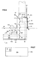
- a pump chamber 28 is formed inside the first column 22a beside the water storage room 26g. As shown in FIG. 6 , a pump 50 is disposed inside the pump chamber 28. The pump 50 is connected to each of the auxiliary rooms 26 of the water storage room 26 via a discharging pipe 50a. By driving the pump 50, it is possible to discharge the ballast water stored inside each of the auxiliary rooms 26 outside the floating body 20 as well as to transfer the ballast water stored in each of the auxiliary rooms 26 to another one of the auxiliary rooms 26.
- a gate 52 is provided for each of the auxiliary rooms 26, by which the auxiliary rooms 26 is communicated to or shut from outside.
- the gate 52 is disposed below the waterline as of the time before the floating body 20 is sunk underwater so as to facilitate injection of the ballast water from outside.
- an air valve 53 is disposed on the upper part of each of the auxiliary rooms 26. When the gate 52 is opened, the air inside the auxiliary room 26 is discharged from the air valve 53 and the ballast water is injected into the auxiliary room 26.
- ballast water it is possible to inject and discharge the ballast water to and from not only the water storage room 26 as a whole but also a plurality of the auxiliary rooms 26 using the above described pump 50, discharge pipe 50a, gate 52, and air valve 53.
- the water storage room 26 capable of adjusting the stored volume of the ballast water is provided inside the floating body 20.
- the volume of the ballast water is adjusted to change the degree of sinking of the floating body 20, and thus to appropriately adjust the degree of sinking for the floating body 20 so as to stabilize the floating body 20 against the drift force F, F' and the rotational moment M, M'.
- the water storage space 26 is divided into a plurality of auxiliary rooms 26 in the longitudinal direction of the lower hull 24, it is possible to prevent the floating body 20 from slanting considerably due to the imbalance of the gravity center of the floating body 20 caused by the ballast water being accumulated in one direction inside the floating body 20.
- a plurality of auxiliary rooms 26 is configured such that the ballast water is injected and discharged to and from each of the auxiliary rooms 26 independently, it is possible to control the gravity center position of the floating body 20 by appropriately adjusting the volume of the ballast water inside each of the auxiliary rooms 26.
- the present configuration in which the water storage room 26 inside the lower hulls 24 is divided into a plurality of the auxiliary rooms 26 in the longitudinal direction, is effective in securing the stability of the floating body 20.
- an attitude detection sensor 56 for detecting the slant of the floating body 20 and a controller 58 for controlling operation of the above described pump 50 are disposed in an electric room 60 provided at the base of the tower 10b.
- the attitude detection sensor 56 detects a slant of the floating body 20 greater than a predetermined value
- the pump 50 starts to operate.
- the volume of the ballast water is automatically controlled so that the floating body 20 becomes horizontal again.
- a communication path 54 is formed inside the lower hull 24.
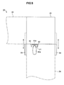
- the communication path 54 is watertightly separated from the auxiliary room 26 where the ballast water is stored.
- the communication path 54 may be constituted of a pipe. The communication path 54 allows persons and objects to transfer between the columns 22 even when the ballast water is stored in the auxiliary room 26.
- a beacon light 23 is disposed on the top face of the column 22, serving to signal the existence of the installation for ships passing by.
- an entrance 44 for providing access inside the columns 22 is provided for the side face of the columns 22.
- the persons or objects are transferred to the floating type wind turbine generating apparatus 1 from the land by a ship 40a or a submarine 40b and then access the inside of the column 22 from the entrance 44.
- the above described entrance 44 is disposed above the connection between the column 22 and the lower hull 24.
- the water depth from the water surface to the part above the lower hull 24 is shallow compared to that from the water surface to other parts.
- the part above the lower hull 24 is less affected by the waves. Therefore, by disposing the entrance 44 on the side face of the column 22 above the connection part between the column 22 and the lower hull 24, access to the floating type wind turbine generating apparatus 1 by the ship 40a or the submarine 40b is facilitated.
- the above described mooring cables 34 extend in such a direction that the mooring cables 34 extend away from the lower hull 24 and do not intersect with the lower hull 24.
- the mooring cables 34 do not interfere with the access of the ship 40a or the submarine 40b to the entrance 44 of the floating type wind turbine generating apparatus 1.
- a hoisting device 42 such as a crane is disposed on the top face of the column 22 above the entrance 44.
- a hoisting device 42 such as a crane is disposed on the top face of the column 22 above the entrance 44.
- an entrance 44a is disposed to on such a position that becomes above the waterline WL in the state where the lower hull 24 is entirely underwater.
- a pair of protrusions 62, 62 extending in the vertical direction is disposed to protrude from the side face of the column 22 for which the entrance 44a is provided.
- the pair of the protrusions 62, 62 is arranged with an interval between each other so that the bow of the ship 40a is housed between the protrusions, the ship being in the state where the end of the bow is in contact with the side face of the column 22.
- An elastic member 41 such as rubber is attached to the bow of the ship 40a to protect the bow.
- a breakwater wall 64 is disposed so as to surround the entrance 44a of the floating body 20.
- the breakwater wall 64 is configured movable so as not to interfere with the access of the ship 40a.
- the breakwater wall 64 is normally disposed on the position where the breakwater wall 64 does not interfere with the access of the ship 40a, for instance, along the side face of the column 22, and is configured to move so as to surround the entrance 44a when the ship 40a is in contact with the side face of the column 22.
- the breakwater wall 64 serves to restrain swaying of the ship 40a due to the waves.
- an entrance 44b is disposed below the waterline WL of the state where the lower hull 24 is entirely underwater.
- the entrance 44b is configured as a hatch to which a submarine 40b is connectable in the state of being watertight as shown in FIG. 6 .
- the entrance 44b is disposed so as to position below the waterline WL while the floating type wind turbine generating apparatus 1 is being moored, and formed into the size that allows the submarine 40b to pass through the entrance 44b.
- a storage room 70 is formed inside the column 22, which is capable of housing the submarine 40b that has passed through the entrance 44b.
- the storage room 70 includes the first room 72 separated from outside by the entrance 44b and the second room 74 separated from the first room 72 by the water blocking gate 76. Once the submarine 40b enters the first room 72 via the entrance 44b, the entrance 44b is closed. Then, by opening the water blocking gate 76 while the entrance 44b is closed, it is possible for the submarine 40b to enter the pool formed inside the second room 74.
- the submarine 40b With the above storage room 70 formed inside the column 22, it is possible for the submarine 40b to access the entrance 44b while being continuously submerged, which is advantageous during bad weather. Also, since it is possible to house the entire submarine 40b in the storage room 70, it is possible to easily transfer a number of persons and cargos into the column 22.
- a guide part 80 for guiding the mooring cables 34a, 34b along the side face of the first column 22a is disposed on the side face of the first column 22a.
- a stopper 90 for preventing the mooring cables 34a, 34b guided by the guide part 80 from falling downward is disposed above the guide part 80.
- a pressing member 66 for pressing and fixing the mooring cables 34a, 34b is disposed on the top face of the first column 22a.
- One guide part 80, stopper 90, and pressing member are provided for each corresponding one of the mooring cables connected to each of the three columns 22.
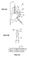
- FIG. 11A is a side view
- FIG. 11B is a front view
- FIG. 11C is a top view of the guide part according to one embodiment of the present invention.
- the guide part 80 comprises a fairlead 80a arranged so that the mooring cable 34 is held between the fairlead 80a and the side face of the column 22. Also, the mooring cable 34 has a chain shape where a plurality of ring members 35 are linked, the ring members 35 being arranged alternately in the longitudinal and lateral direction.
- the fairlead 80a includes a pair of supporting members 82 protruding from the side face of the column 22 and a rotating body 84 which is rotatably supported between the pair of the supporting members 82.
- a plurality of projections 86 is formed on the outer circumference of the rotating body 84 with a pitch corresponding to the length of the ring member 35, for instance, a pitch corresponding to the distance P between the centers of the ring members 35 that are distanced by one ring member in between as shown in FIG. 11 .
- a slit 86a is provided for the projection 86 at the center part as seen from the front as shown in FIG. 11B .
- the ring member 35 arranged in the longitudinal direction with respect to the rotating body 84 is inserted into the slit 86a.
- the ring member 35 arranged in the lateral direction with respect to the rotating body 84 is housed in the flat portion 87 between the adjacent projections 86 on the outer circumference of the rotating body 84.
- the mooring cable 34 is guided along the side face of the column 22 in the vertical direction.
- the mooring cable 34 extending slantwise from the anchor 32 toward the side face of the column 22 in catenary curve is smoothly guided along the side face of the column 22 in the vertical direction. Also, by the ring member 35 being inserted into the slit 86a of the projection 86 formed on the outer circumference of the rotating member 84 of the fairlead 80a, the mooring cable 34 is securely guided without misalignment.
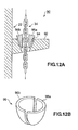
- FIG. 12A is a cross-sectional view of the stopper according to one embodiment of the present invention.
- the stopper 90 includes a protruding member 92 protruding from the side face of the column 22 and wedge members 96a, 96b having a wedge shape.
- a through-hole 94 is formed on the protruding member 92, whose opening increases upward in size, and the mooring cable 34 is inserted through the through-hole 94.
- the wedge members 96a, 96b are fit into the through-hole 94 from above.
- the mooring cable 34 is fixed by the frictional force between the mooring cable 34 and the wedge members 96a, 96b to prevent the mooring cable 34 from falling down.
- wedge members 96a, 96b are suitably used, which are formed by halving a cup-shape member having a shape that can be fit into the through-hole 94 from above as shown in FIG. 12B .
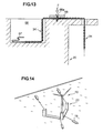
- FIG. 13 is a cross-sectional view of a part of the top face of the column according to one embodiment of the present invention.
- a pressing member 66 is disposed on the top face of the column 22 fixed onto the top face of the column 22 by a bolt 66a in the state where the mooring cable 34 is held between the pressing member 66 and the top face of the column 22.
- the mooring cable 34 is forced against the top face of the column 22 by the pressing member 66 with the predetermined pressing force F.
- the pressing member 66 being provided, the mooring cable 34 guided along the side face of the column 22 is fixed onto the top face of the column 22. As a result, it is possible to prevent the end of the mooring cable 34 from moving freely.
- a housing space 68 for housing the mooring cable 34 is provided inside the column 22.
- the housing space 68 has its opening formed on the top face of the column 22 and houses an extra part at the end of the mooring cable 34 fixed by the pressing member 66.
- a rope 67 is connected to the end of the mooring cable 34 at the side connected to the column. By connecting the rope 67 to the end of the mooring cable 34, it would be easier to handle the mooring cable 34 in the case where the mooring cable 34 is arranged along the side face of the column 22 via the guide part 80 and the like.
- FIG. 14 is an illustration of the state where the floating type wind turbine generating apparatus is being towed.
- FIG. 15A is an illustration of the step of fixing the anchor to the predetermined position on the bottom of the water.
- FIG. 16 is an illustration of the step of connecting the mooring cable and the floating body.
- the floating body 20 is assembled in the state of being on the land or in contact with the shore.
- the wind turbine generator 10 is installed on the floating body 20.
- the floating body 20 is towed to the prescribed mooring position on the ocean by four towing ships 15, for instance.
- a ship other than the floating body 20 a crane vessel 16 for instance, is used to sink the anchor 32 connected to the above described mooring cable 34 to a predetermined position on the bottom of the water (sinking step). Then, as shown in FIG. 15B , the crane vessel 16 is used to tow the mooring cable 34 to fix the sunken anchor 32 to the bottom of the water (towing step).
- the holding power of the mooring cable 34 is measured. As a result, it is possible to easily measure the holding power of the mooring cable 34 and thus to easily determine whether the anchor 32 is appropriately fixed on the bottom of the water.
- the sinking step and towing step are iterated for each of the mooring cables 34 to fix the anchors 32 of the mooring cables 34 to the predetermined position on the bottom of the water.
- the crane vessel 16 by coupling the mooring cables 34 together and towing the coupled mooring cables 34 collectively by the crane vessel 16, it is possible to fix the sunken anchors collectively on the bottom of the water.
- the rope 67 connected to the end of the mooring cable 34 is attached to a buoy, which is then floated on the prescribed mooring position. Then, the mooring cables 34 attached to the buoys is retrieved by the floating body 20 towed to the prescribed mooring position, and the retrieved mooring cables 34 are connected to the columns 22 as shown in the above described FIG. 3 . Finally, by injecting the ballast water into the water storage space inside the floating body 20, the floating type wind turbine generating apparatus 1 is moored on the ocean and the like in the state where the waterline WL is positioned above the top face of the lower hull 24.
- the above mooring method of the floating type wind turbine generating apparatus 1 it is possible to fix the anchors 32 on the predetermined position on the bottom of the water and connect the floating body 20 and the anchors 32 by the mooring cables 34 without providing a crane for the floating body 20 itself. As a result, it is possible to enhance efficiency of the mooring process and to reduce the cost of the mooring process.
- the present invention is applicable to a floating type wind turbine generating apparatus installed on the ocean and the like.
Landscapes
- Engineering & Computer Science (AREA)
- Chemical & Material Sciences (AREA)
- Combustion & Propulsion (AREA)
- Mechanical Engineering (AREA)
- Ocean & Marine Engineering (AREA)
- Life Sciences & Earth Sciences (AREA)
- Sustainable Development (AREA)
- Sustainable Energy (AREA)
- General Engineering & Computer Science (AREA)
- Physics & Mathematics (AREA)
- Fluid Mechanics (AREA)
- Wind Motors (AREA)
Abstract
Description
- This disclosure relates to a floating type wind turbine generating apparatus including a floating body floating on the water surface and a wind turbine generator installed on the floating body.
- In the case where a wind turbine generating apparatus is to be installed on the ocean and the like, a bottom-mounted type wind turbine generating apparatus is generally employed in a region where the water is shallow. A bottom-mounted type wind turbine generating apparatus includes a base disposed on the bottom of the water, and a wind turbine generator disposed on the base. However, in a region where the water is deep, the bottom-mounted type wind turbine generating apparatus is uneconomic. Therefore, a floating type wind turbine generating apparatus would be employed.
- The floating type wind turbine generating apparatus includes a floating body floating on the water surface and a wind turbine generator installed on the floating body. Various types have been proposed for such a floating type wind turbine generating apparatus (
Patent Documents 1 to 4). -
- Patent Document 1:
JP2011-521820A - Patent Document 2:
JP2001-165032 - Patent Document 3:
JP4743953B - Patent Document 4:
JP2770449B - For the above described floating type wind turbine generating apparatus, it is necessary to perform regular maintenance such as check and replacement of the instruments even after mooring the floating type wind turbine generating apparatus on the ocean and the like. Thus, there is a need for a floating type wind turbine generating apparatus which can be easily accessed by a ship and the like without affected by the offshore conditions as little as possible. However, accessibility after having been moored on the ocean and the like is hardly taken into consideration for the floating type wind turbine generating apparatus in the above described prior art.
- At least one embodiment of the present invention was made in view of the problems described above, and is to provide a floating type wind turbine generating apparatus which can be easily accessed by a ship and the like after having been moored on the ocean and the like.
- In order to achieve the above described object, in at least one embodiment of the present invention, a floating type wind turbine generating apparatus comprises:
- a floating body including three columns and at least two lower hulls connecting two of the three columns; and
- a wind turbine generator disposed on a top face of at least one of the three columns,
- wherein the floating body is configured to be moored on a water surface in a state where a waterline is positioned above top faces of the lower hulls by injecting a ballast water inside; and
- wherein an entrance is provided for a side face of at least one of the three columns, the entrance being disposed above a connection between the lower hull and the at least one column, and configured to provide access inside the at least one column.
- In the floating type wind turbine generating apparatus installed on the water surface in the state where the waterline is positioned above the top faces of the lower hulls, the parts above the lower hulls are less likely to be affected by waves than other parts. Thus, by providing an entrance at the side face of the lower hull above the connection of the lower hull and the column, access to the floating type wind turbine generating apparatus by a ship or submarine would be facilitated.
- Further, in the floating type wind turbine generating apparatus of one embodiment of the present invention, the floating body includes a water storage space inside the floating body, the water storage space being configured capable of adjusting a stored volume of the ballast water.
- With such storage space provided inside the floating body, it is possible to adjust the height or depth of the entrance from the water surface appropriately for an accessing ship or submarine by adjusting the volume of the ballast water in the water storage space.
- Further, in the floating type wind turbine generating apparatus of one embodiment of the present invention, the water storage space provided inside the floating body is divided into a plurality of auxiliary rooms in a longitudinal direction of each of the lower hulls, each of the auxiliary rooms being configured capable of taking in and discharging the ballast water.
- With the water storage space divided into auxiliary rooms in the longitudinal direction of the lower hull, it is possible to prevent the floating body from being slanted considerably due to the imbalance of the gravity center of the floating body caused by the ballast water being accumulated in one direction inside the floating body. Also, as the plurality of auxiliary rooms is configured such that the ballast water is injected and discharged to and from each of the auxiliary rooms independently, it is possible to control the gravity center position of the floating body by appropriately adjusting the volume of the ballast water inside each of the auxiliary rooms.
- Further, the floating type wind turbine generating apparatus in one embodiment of the present invention further includes an attitude detection sensor configured to detect an attitude of the floating body, wherein a volume of the ballast water stored in each of the auxiliary rooms is controlled based on a detected value of the attitude detection sensor.
- With the above configuration, it is possible to control the attitude of the floating body with higher accuracy based on the detected value of the attitude detection sensor.
- Further, in the floating type wind turbine generating apparatus of one embodiment of the present invention, a communication path is provided inside the floating body and configured to communicate between the three columns.
- With the above communication path provided inside the floating body, it is possible for persons and objects to transfer between the columns even when the lower hulls are submerged. This communication path may include lifting means such as a ladder, stairs, and an elevator, or may include means for supporting conveyance of objects such as a crane.
- Further, in the floating type wind turbine generating apparatus of one embodiment of the present invention, each of the three columns has at least one mooring cable connected thereto, and the mooring cable extends in such a direction that the mooring cable does not intersect with the lower hull and extends away from the lower hulls.
- With the mooring cables connected to the columns extending in the above direction, the mooring cables do not interfere with access of a ship or submarine.
- Further, in the floating type wind turbine generating apparatus of one embodiment of the present invention, the floating body includes a movable breakwater wall disposed so as to surround the entrance.
- With the above breakwater wall, it is possible to reduce the influence of the surrounding environments on a ship or submarine accessing the entrance. The breakwater wall is configured movable so as not to interfere with the access of a ship or submarine.
- Further, in the floating type wind turbine generating apparatus of one embodiment of the present invention, the entrance is configured to be positioned above the waterline while the floating body is moored, a pair of protrusions extending in a vertical direction is disposed on the side face of the column for which the entrance is provided, and the pair of the protrusions is arranged with an interval between each other so that a bow of a ship is housed between the protrusions, the ship being in a state where an end of the bow is in contact with the side face of the column.
- With the pair of the protrusions disposed on the side face of the column, on which the entrance is provided, with an interval between each other so as to house the bow of a ship, it is possible to dock the ship to the shore by inserting the bow between the protrusions in the state where the ship is continuously being propelled. As a result, the influence by wave and the like on the ship is reduced, thereby facilitating the access to the entrance.
- Further, in the floating type wind turbine generating apparatus of one embodiment of the present invention, the entrance comprises a hatch disposed so as to be positioned below the waterline while the floating body is moored, the hatch being configured such that a submarine is connectable.
- With the hatch disposed on the side face of the column, it is possible for a submarine to access the entrance in the state of being submerged. The submarine is less affected by waves, which is advantageous in bad weather.
- Further, in the floating type wind turbine generating apparatus of one embodiment of the present invention, the entrance is disposed so as to be positioned below the waterline while the floating body is moored and has a size that allows a submarine to pass through the entrance, and a storage room is formed inside the column, the storage room being configured capable of housing a submarine that has passed through the entrance.
- With the above configuration, a submarine is capable of accessing the entrance in the state of being submerged, which is advantageous in bad weather. Also, as it is possible to house the submarine entirely in the housing room, it is possible to easily transfer a number of persons and cargos into the column.
- According to at least one embodiment of the present invention, it is possible to provide a floating type wind turbine generating apparatus which can be easily accessed by a ship and the like after having been moored on the ocean and the like.
-
-
FIG. 1 is an oblique view of the floating type wind turbine generating apparatus according to one embodiment of the present invention in the state where the floating body is moored on the ocean. -
FIG. 2 is a side view of the floating type wind turbine generating apparatus ofFIG. 1 as seen from aside. -
FIG. 3 is a planar view of the arrangement of the mooring cables of the floating type wind turbine generating apparatus according to one embodiment of the present invention. -
FIG. 4 is a planar view of the floating type wind turbine generating apparatus according to one embodiment of the present invention. -
FIG. 5 is a cross-sectional view taken along line A-A ofFIG. 4 as seen from aside. -
FIG. 6 is a cross-sectional enlarged view of the part "a" ofFIG. 5 . -
FIG. 7 is a cross-sectional view of the communication path according to one embodiment of the present invention. -
FIG. 8 is an oblique view of the pair of protrusions according to one embodiment of the present invention. -
FIG. 9 is a planar view of the arrangement of the breakwater wall according to one embodiment of the present invention. -
FIG. 10 is a cross-sectional view of the storage room according to one embodiment of the present invention. -
FIG. 11A is a side view,FIG. 11B is a front view, andFIG. 11C is a top view of the guide part according to one embodiment of the present invention. -
FIG. 12A is a cross-sectional view of the stopper according to one embodiment of the present invention. -
FIG. 12B is an oblique view of one embodiment of the wedge member. -
FIG. 13 is a cross-sectional view of a part of the top face of the column according to one embodiment of the present invention. -
FIG. 14 is an illustration of the state where the floating type wind turbine generating apparatus is being towed. -
FIGs. 15 is an illustration of the step of fixing the anchor to the predetermined position on the bottom of the water. - Embodiments of the present invention will now be described in detail with reference to the accompanying drawings. It is intended, however, that unless particularly specified, dimensions, materials, shapes, relative positions and the like of components described in the embodiments shall be interpreted as illustrative only and not limitative of the scope of the present invention.
-
FIG. 1 is an oblique view of the floating type wind turbine generating apparatus according to one embodiment of the present invention in the state where the floating body is moored on the ocean.FIG. 2 is a side view of the floating type wind turbine generating apparatus ofFIG. 1 as seen from aside. - As show in
FIGs. 1 and2 , the floating type windturbine generating apparatus 1 according to the present invention includes a floatingbody 20 floating on the water surface and awind turbine generator 10 disposed on the floatingbody 20. - As shown in
FIGs. 1 and2 , thewind turbine generator 10 includes anacelle 10a, atower 10b disposed standing upright on the top face of thefirst column 22a, and ablade 10c rotatably mounted to thenacelle 10a. Thenacelle 10a is supported by thetower 10b so as to be rotatable around the axial direction of thetower 10b. Thenacelle 10a orients theblade 10c to the upwind side in accordance with the wind direction. By theblade 10c rotating upon receiving wind, power generation is performed by the generator not shown in the drawings. - As shown in
FIG. 1 , the floatingbody 20 includes three columns 22 (22a, 22b, 22c) having a quadratic prism shape and disposed on the vertex positions of the virtual triangle in the planar view. Also, the floatingbody 20 includes the firstlower hull 24a of an elongated shape connecting thefirst column 22a and thesecond column 22b, and the secondlower hull 24b of an elongated shape connecting thefirst column 22a and thethird column 22c. Accordingly, the floatingbody 20 is formed into a substantially V-shape in the planar view by the threecolumns 22 and twolower hulls 24. The above describedwind turbine generator 10 is disposed on the top face of thefirst column 22a positioned in the middle of the substantially V-shape in the planar view. - In one embodiment of the present embodiment, the first
lower hull 24a and the secondlower hull 24b are mutually orthogonal. The above described threecolumns 22 are disposed on the vertex positions of the virtual isosceles right triangle which is symmetric about the bisector of the intersecting angle between the firstlower hull 24a and the secondlower hull 24b. - Further in one embodiment of the present embodiment, although not specifically shown in the drawings, the third lower hull may be further provided connecting the
second column 22b and thethird column 22c. Also, the firstlower hull 24a and the secondlower hull 24b may be connected to each other by a reinforcing beam member. - Further, as described below, the floating
body 20 includes a water storage space inside, which stores the ballast water. By injecting the ballast water into the water storage space, the floatingbody 20 is moored on the water surface in the state where the water line WL is positioned above the top faces of thelower hulls 24. - Further, as shown in
FIGs. 1 and2 , the floatingbody 20 is arranged so that thefirst column 22a is positioned on the upwind side in the main wind direction W. Thewind turbine generator 10 is installed on the top face of thefirst column 22a. On the other hand, thesecond column 22b and thethird column 22c are arranged to be positioned on the downwind side with respect to thefirst column 22a in the main wind direction W. It is possible to increase stability of thewind turbine generator 10, which may lean to the back side upon receiving wind load, by arranging thefirst column 22a on which thewind turbine generator 10 is installed on the upwind side in the main wind direction W. - Further, as shown in
FIG. 2 , a plurality ofmooring cables 34 is connected to the floatingbody 20 in a catenary curve so as to show catenary curves. Themooring cables 34 are connected to theanchors 32 fixed on the bottom E of the water. The floatingbody 20 is moored on the ocean by theanchors 32 and themooring cables 34, resisting the drift force and rotational moment acting on the floatingbody 20. -
FIG. 3 is a planar view of the arrangement of the mooring cables of the floating type wind turbine generating apparatus according to one embodiment of the present invention. - As shown in
FIG. 3 , in one embodiment of the present invention, twomooring cables first column 22a. The twomooring cables lower hull 24a and the secondlower hull 24b. Also, threemooring cables mooring cables second column 22b and thethird column 22c. In this manner, the floatingbody 20 as a whole includes 8mooring cables 34a to 34h in total connected thereto. Each of the 8mooring cables 34 is arranged to radially extend from the floatingbody 20 so as not to intersect with one another in the planar view. - In one embodiment of the present invention, at least two
mooring cables 34 are connected to thefirst column 22a disposed on the upwind side in the main wind direction W, while at least onemooring cable 34 is connected to each of thesecond column 22b andthird column 22c disposed on the downwind side in the main direction W. With this configuration, the at least twomooring cables 34 connected to thefirst column 22a resist the drift force F in the main wind direction W acting on the floatingbody 20, while the at least onemooring cable 34 connected to each of thesecond column 22b and thethird column 22c resists the drift force F' in the other directions and the rotational moment M, M' around thefirst column 22a acting on the floatingbody 20. As a result, the floatingbody 20 is stably moored against the drift force F, F' and rotational moment M, M' acting on the floatingbody 20. - Further, in one embodiment of the present invention, as shown in
FIG. 3 , the at least onemooring cable 34 connected to thesecond column 22b includes themooring cable 34c (rotation preventing mooring cable) which extends toward the region α on thefirst column 22a side. The region α is defined by the bisector "a" of the intersection of the firstlower hull 24a and the secondlower hull 24b, and the straight line "b", which is orthogonal to the bisector "a" and passes through the center of thesecond column 22b. Similarly, the at least onemooring cable 34 connected to thethird column 22c includes themooring cable 34h (rotation preventing mooring cable) which extends toward the region β on thefirst column 22a side. The region β is defined by the bisector "a" and the straight line "c", which is orthogonal to the bisector "a" and passes through the center of thethird column 22c. In this manner, the mooring cables 34 (rotation preventing mooring cable) connected to thesecond column 22b and thethird column 22c extend in the direction such that themooring cables 34 effectively resist the rotational moment M, M' around thefirst column 22a. As a result, the floatingbody 20 is stably moored. - At this time, by the mooring cables 34 (rotation preventing mooring cable) that extend toward the above described region α and region β also extending in the direction orthogonal to the axial direction of the
lower hull 24a and thelower hull 24b, similarly to themooring cable 34c and themooring cable 34h shown inFIG. 3 , the floatingbody 20 would be even more stably moored because in this manner themooring cables 34 extend in the direction 180 degrees opposite to the tangent line of the rotational force when the floatingbody 20 is about to rotate around thefirst column 22, which makes it possible for themooring cables 34 to resist the rotational moment M, M' more effectively. - Also at this time, by a plurality of the
mooring cables 34 being connected to each of thesecond column 22b and thethird column 22c as shown inFIG. 3 , it is possible to moor the floatingbody 20 even more stably against the drift force F, F' or the rotational moment M, M' acting on the floatingbody 20, as well as to prevent the floatingbody 20 from immediately becoming unstable due to the drift force F, F' or the rotational moment M, M' even when one of themooring cables 34 is cut off. - Also at this time, when a plurality of the
mooring cables 34 are connected to each of thesecond column 22b and thethird column 22c as described above, the mooring cables 34 (34d, 34e, 34f, 34g) may be connected along the axial directions of thelower hulls 24, extending toward the region α' and region P' on the opposite side of thefirst column 22a beside the mooring cables 34 (34c, 34h) extending in the direction orthogonal to the axial directions of thelower hulls 24. By connecting such mooring cables 34 (34d, 34e, 34f, 34g) to thesecond column 22b and thethird column 22c, the floatingbody 20 would be stably moored particularly against the drift force F' in the direction opposite to the main wind direction W. -
FIG. 4 is a planar view of the floating type wind turbine generating apparatus according to one embodiment of the present invention.FIG. 5 is a cross-sectional view taken along line A-A ofFIG. 4 .FIG. 6 is a cross-sectional enlarged view of the part "a" ofFIG. 5 .FIG. 7 is a cross-sectional view taken along line B-B ofFIG. 6 . - The above described
column 22 andlower hull 24 have a cross-section of a hollow shape. As shown inFIGs. 4 and5 , a water storage space for storing the ballast water is formed inside thecolumn 22 and thelower hull 24. - In one embodiment of the present invention, the water storage space formed inside the
lower hull 24 is divided into a plurality of auxiliary rooms (water storage rooms) 26 in the longitudinal direction of thelower hull 24. For instance, as shown inFIGs. 4 and5 , three auxiliary rooms (26a∼26c and 26d∼26f) are formed in the longitudinal direction inside the firstlower hull 24a and the secondlower hull 24b. - As shown in
FIG. 5 , twoauxiliary rooms third column 22c by being divided in the vertical direction. Although not shown, two auxiliary rooms are similarly formed inside thesecond column 22b by being divided in the vertical direction. - A
pump chamber 28 is formed inside thefirst column 22a beside thewater storage room 26g. As shown inFIG. 6 , apump 50 is disposed inside thepump chamber 28. Thepump 50 is connected to each of the auxiliary rooms 26 of the water storage room 26 via a dischargingpipe 50a. By driving thepump 50, it is possible to discharge the ballast water stored inside each of the auxiliary rooms 26 outside the floatingbody 20 as well as to transfer the ballast water stored in each of the auxiliary rooms 26 to another one of the auxiliary rooms 26. - Also shown in
FIG. 6 , agate 52 is provided for each of the auxiliary rooms 26, by which the auxiliary rooms 26 is communicated to or shut from outside. Thegate 52 is disposed below the waterline as of the time before the floatingbody 20 is sunk underwater so as to facilitate injection of the ballast water from outside. Also, anair valve 53 is disposed on the upper part of each of the auxiliary rooms 26. When thegate 52 is opened, the air inside the auxiliary room 26 is discharged from theair valve 53 and the ballast water is injected into the auxiliary room 26. - As described above, in one embodiment of the present invention, it is possible to inject and discharge the ballast water to and from not only the water storage room 26 as a whole but also a plurality of the auxiliary rooms 26 using the above described
pump 50,discharge pipe 50a,gate 52, andair valve 53. - As described above, the water storage room 26 capable of adjusting the stored volume of the ballast water is provided inside the floating
body 20. As a result, it is possible to adjust the volume of the ballast water to change the degree of sinking of the floatingbody 20, and thus to appropriately adjust the degree of sinking for the floatingbody 20 so as to stabilize the floatingbody 20 against the drift force F, F' and the rotational moment M, M'. - Further, as the water storage space 26 is divided into a plurality of auxiliary rooms 26 in the longitudinal direction of the
lower hull 24, it is possible to prevent the floatingbody 20 from slanting considerably due to the imbalance of the gravity center of the floatingbody 20 caused by the ballast water being accumulated in one direction inside the floatingbody 20. Also, as a plurality of auxiliary rooms 26 is configured such that the ballast water is injected and discharged to and from each of the auxiliary rooms 26 independently, it is possible to control the gravity center position of the floatingbody 20 by appropriately adjusting the volume of the ballast water inside each of the auxiliary rooms 26. - It is difficult for the floating
body 20 with thelower hulls 24 entirely under the water to return to the original attitude once it is slanted by external force such as waves acting thereon. Thus, the present configuration, in which the water storage room 26 inside thelower hulls 24 is divided into a plurality of the auxiliary rooms 26 in the longitudinal direction, is effective in securing the stability of the floatingbody 20. - In one embodiment of the present invention, as shown in
FIG. 6 , anattitude detection sensor 56 for detecting the slant of the floatingbody 20 and acontroller 58 for controlling operation of the above describedpump 50 are disposed in anelectric room 60 provided at the base of thetower 10b. When theattitude detection sensor 56 detects a slant of the floatingbody 20 greater than a predetermined value, thepump 50 starts to operate. As a result, the volume of the ballast water is automatically controlled so that the floatingbody 20 becomes horizontal again. - In one embodiment of the present invention, as shown in
FIG. 7 , acommunication path 54 is formed inside thelower hull 24. Thecommunication path 54 is watertightly separated from the auxiliary room 26 where the ballast water is stored. Thecommunication path 54 may be constituted of a pipe. Thecommunication path 54 allows persons and objects to transfer between thecolumns 22 even when the ballast water is stored in the auxiliary room 26. - Also, as shown in
FIGs. 4 and5 , abeacon light 23 is disposed on the top face of thecolumn 22, serving to signal the existence of the installation for ships passing by. - In one embodiment of the present invention, as shown in
FIGs. 4 and5 , anentrance 44 for providing access inside thecolumns 22 is provided for the side face of thecolumns 22. When transferring persons or objects to the floating type windturbine generating apparatus 1 moored on the ocean and the like, the persons or objects are transferred to the floating type windturbine generating apparatus 1 from the land by aship 40a or asubmarine 40b and then access the inside of thecolumn 22 from theentrance 44. - The above described
entrance 44 is disposed above the connection between thecolumn 22 and thelower hull 24. The water depth from the water surface to the part above thelower hull 24 is shallow compared to that from the water surface to other parts. Thus, the part above thelower hull 24 is less affected by the waves. Therefore, by disposing theentrance 44 on the side face of thecolumn 22 above the connection part between thecolumn 22 and thelower hull 24, access to the floating type windturbine generating apparatus 1 by theship 40a or thesubmarine 40b is facilitated. - Further, as shown in
FIG. 4 , the above describedmooring cables 34 extend in such a direction that themooring cables 34 extend away from thelower hull 24 and do not intersect with thelower hull 24. Thus, themooring cables 34 do not interfere with the access of theship 40a or thesubmarine 40b to theentrance 44 of the floating type windturbine generating apparatus 1. - Further, as shown in
FIGs. 5 and6 , ahoisting device 42 such as a crane is disposed on the top face of thecolumn 22 above theentrance 44. By providing thehoisting device 42 above theentrance 44, it is possible to easily perform the work for carrying the cargo on theship 40a into thecolumn 22. - In one embodiment of the present invention, as shown in
FIGs. 5 and6 , anentrance 44a is disposed to on such a position that becomes above the waterline WL in the state where thelower hull 24 is entirely underwater. By providing theentrance 44a above the waterline WL, the access to the inside of thecolumn 22 by theship 40a is facilitated. - In one embodiment of the present invention, as shown in
FIG. 8 , a pair ofprotrusions column 22 for which theentrance 44a is provided. The pair of theprotrusions ship 40a is housed between the protrusions, the ship being in the state where the end of the bow is in contact with the side face of thecolumn 22. Anelastic member 41 such as rubber is attached to the bow of theship 40a to protect the bow. - With the above pair of the
protrusions 62 disposed on the side face of thecolumn 22, it is possible to dock theship 40a to the shore by inserting the bow between theprotrusions 62 in the state of theship 40a being propelled. As a result, the influence by the wave and the like on theship 40a is reduced, thus facilitating the access to theentrance 44a. - In one embodiment of the present invention, as shown in
FIG. 9 , abreakwater wall 64 is disposed so as to surround theentrance 44a of the floatingbody 20. Thebreakwater wall 64 is configured movable so as not to interfere with the access of theship 40a. Thebreakwater wall 64 is normally disposed on the position where thebreakwater wall 64 does not interfere with the access of theship 40a, for instance, along the side face of thecolumn 22, and is configured to move so as to surround theentrance 44a when theship 40a is in contact with the side face of thecolumn 22. As a result, thebreakwater wall 64 serves to restrain swaying of theship 40a due to the waves. - In one embodiment of the present invention, as shown in
FIGs. 5 and6 , anentrance 44b is disposed below the waterline WL of the state where thelower hull 24 is entirely underwater. In one embodiment, theentrance 44b is configured as a hatch to which asubmarine 40b is connectable in the state of being watertight as shown inFIG. 6 . - With
such entrance 44b disposed on the side face of thecolumn 22, it is possible for thesubmarine 40b to access theentrance 44b in the state of being submerged. Thesubmarine 40b navigating underwater is less affected by waves, which is advantageous when accessing the floating type windturbine generating apparatus 1 during bad weather. - In one embodiment of the present invention, as shown in
FIG. 10 , theentrance 44b is disposed so as to position below the waterline WL while the floating type windturbine generating apparatus 1 is being moored, and formed into the size that allows thesubmarine 40b to pass through theentrance 44b. Astorage room 70 is formed inside thecolumn 22, which is capable of housing thesubmarine 40b that has passed through theentrance 44b. - The
storage room 70 includes thefirst room 72 separated from outside by theentrance 44b and thesecond room 74 separated from thefirst room 72 by thewater blocking gate 76. Once thesubmarine 40b enters thefirst room 72 via theentrance 44b, theentrance 44b is closed. Then, by opening thewater blocking gate 76 while theentrance 44b is closed, it is possible for thesubmarine 40b to enter the pool formed inside thesecond room 74. - With the
above storage room 70 formed inside thecolumn 22, it is possible for thesubmarine 40b to access theentrance 44b while being continuously submerged, which is advantageous during bad weather. Also, since it is possible to house theentire submarine 40b in thestorage room 70, it is possible to easily transfer a number of persons and cargos into thecolumn 22. - In one embodiment of the present invention, as shown in
FIG. 6 , aguide part 80 for guiding themooring cables first column 22a is disposed on the side face of thefirst column 22a. Also, astopper 90 for preventing themooring cables guide part 80 from falling downward is disposed above theguide part 80. Moreover, a pressingmember 66 for pressing and fixing themooring cables first column 22a. Oneguide part 80,stopper 90, and pressing member are provided for each corresponding one of the mooring cables connected to each of the threecolumns 22. -
FIG. 11A is a side view,FIG. 11B is a front view, andFIG. 11C is a top view of the guide part according to one embodiment of the present invention. - As shown in
FIGs. 11A to 11C , theguide part 80 according to one embodiment of the present invention comprises afairlead 80a arranged so that themooring cable 34 is held between thefairlead 80a and the side face of thecolumn 22. Also, themooring cable 34 has a chain shape where a plurality ofring members 35 are linked, thering members 35 being arranged alternately in the longitudinal and lateral direction. - The
fairlead 80a includes a pair of supportingmembers 82 protruding from the side face of thecolumn 22 and arotating body 84 which is rotatably supported between the pair of the supportingmembers 82. A plurality ofprojections 86 is formed on the outer circumference of therotating body 84 with a pitch corresponding to the length of thering member 35, for instance, a pitch corresponding to the distance P between the centers of thering members 35 that are distanced by one ring member in between as shown inFIG. 11 . Aslit 86a is provided for theprojection 86 at the center part as seen from the front as shown inFIG. 11B . Thering member 35 arranged in the longitudinal direction with respect to therotating body 84 is inserted into theslit 86a. Also, as shown inFIG. 11C , thering member 35 arranged in the lateral direction with respect to therotating body 84 is housed in theflat portion 87 between theadjacent projections 86 on the outer circumference of therotating body 84. By thering member 35 being inserted into theslit 86a of theprojection 86, themooring cable 34 is guided along the side face of thecolumn 22 in the vertical direction. - With the above described
guide part 80 andfairlead 80a, themooring cable 34 extending slantwise from theanchor 32 toward the side face of thecolumn 22 in catenary curve is smoothly guided along the side face of thecolumn 22 in the vertical direction. Also, by thering member 35 being inserted into theslit 86a of theprojection 86 formed on the outer circumference of the rotatingmember 84 of thefairlead 80a, themooring cable 34 is securely guided without misalignment. -
FIG. 12A is a cross-sectional view of the stopper according to one embodiment of the present invention. - As shown in
FIG. 12A , thestopper 90 includes a protrudingmember 92 protruding from the side face of thecolumn 22 andwedge members - As also shown in
FIG. 12A , a through-hole 94 is formed on the protrudingmember 92, whose opening increases upward in size, and themooring cable 34 is inserted through the through-hole 94. In the state where themooring cable 34 is inserted through the through-hole 94, thewedge members hole 94 from above. As a result, by the so-called wedge effect, themooring cable 34 is fixed by the frictional force between themooring cable 34 and thewedge members mooring cable 34 from falling down. - In one embodiment of the present invention, as a
wedge member 96,wedge members hole 94 from above as shown inFIG. 12B . -
FIG. 13 is a cross-sectional view of a part of the top face of the column according to one embodiment of the present invention. - As shown in
FIG. 13 , a pressingmember 66 is disposed on the top face of thecolumn 22 fixed onto the top face of thecolumn 22 by abolt 66a in the state where themooring cable 34 is held between the pressingmember 66 and the top face of thecolumn 22. Themooring cable 34 is forced against the top face of thecolumn 22 by the pressingmember 66 with the predetermined pressing force F. With such pressingmember 66 being provided, themooring cable 34 guided along the side face of thecolumn 22 is fixed onto the top face of thecolumn 22. As a result, it is possible to prevent the end of themooring cable 34 from moving freely. - As shown in
FIG. 13 , ahousing space 68 for housing themooring cable 34 is provided inside thecolumn 22. Thehousing space 68 has its opening formed on the top face of thecolumn 22 and houses an extra part at the end of themooring cable 34 fixed by the pressingmember 66. - A
rope 67 is connected to the end of themooring cable 34 at the side connected to the column. By connecting therope 67 to the end of themooring cable 34, it would be easier to handle themooring cable 34 in the case where themooring cable 34 is arranged along the side face of thecolumn 22 via theguide part 80 and the like. - Next, a mooring method for the floating type wind
turbine generating apparatus 1 with the above configuration will be described in accordance withFIGs. 14 to 16 .FIG. 14 is an illustration of the state where the floating type wind turbine generating apparatus is being towed.FIG. 15A is an illustration of the step of fixing the anchor to the predetermined position on the bottom of the water. FIG. 16 is an illustration of the step of connecting the mooring cable and the floating body. - In the mooring method of the floating type wind
turbine generating apparatus 1 according to at least one embodiment of the present invention, the floatingbody 20 is assembled in the state of being on the land or in contact with the shore. Thewind turbine generator 10 is installed on the floatingbody 20. Then, as shown inFIG. 14 , the floatingbody 20 is towed to the prescribed mooring position on the ocean by four towingships 15, for instance. - Further, as shown in
FIG. 15A , a ship other than the floatingbody 20, acrane vessel 16 for instance, is used to sink theanchor 32 connected to the above describedmooring cable 34 to a predetermined position on the bottom of the water (sinking step). Then, as shown inFIG. 15B , thecrane vessel 16 is used to tow themooring cable 34 to fix thesunken anchor 32 to the bottom of the water (towing step). - In the towing step, based on the output torque of the power supply for towing the
mooring cable 34 or the tension of themooring cable 34 being towed, the holding power of themooring cable 34 is measured. As a result, it is possible to easily measure the holding power of themooring cable 34 and thus to easily determine whether theanchor 32 is appropriately fixed on the bottom of the water. - Then, the sinking step and towing step are iterated for each of the
mooring cables 34 to fix theanchors 32 of themooring cables 34 to the predetermined position on the bottom of the water. At this time, by coupling themooring cables 34 together and towing the coupledmooring cables 34 collectively by thecrane vessel 16, it is possible to fix the sunken anchors collectively on the bottom of the water. As a result, it is possible to reduce the number of the towing operations, thereby increasing efficiency of the mooring process and reducing the cost. - After having fixed the
anchors 32 to the bottom of the water by thecrane vessel 16, therope 67 connected to the end of themooring cable 34 is attached to a buoy, which is then floated on the prescribed mooring position. Then, themooring cables 34 attached to the buoys is retrieved by the floatingbody 20 towed to the prescribed mooring position, and the retrievedmooring cables 34 are connected to thecolumns 22 as shown in the above describedFIG. 3 . Finally, by injecting the ballast water into the water storage space inside the floatingbody 20, the floating type windturbine generating apparatus 1 is moored on the ocean and the like in the state where the waterline WL is positioned above the top face of thelower hull 24. - According to the above mooring method of the floating type wind
turbine generating apparatus 1, it is possible to fix theanchors 32 on the predetermined position on the bottom of the water and connect the floatingbody 20 and theanchors 32 by themooring cables 34 without providing a crane for the floatingbody 20 itself. As a result, it is possible to enhance efficiency of the mooring process and to reduce the cost of the mooring process. - Embodiments of the present invention were described in detail above, but the present invention is not limited thereto, and various amendments and modifications may be implemented within a scope that does not depart from the present invention.
- The present invention is applicable to a floating type wind turbine generating apparatus installed on the ocean and the like.
-
- 1
- Floating wind turbine generating apparatus
- 10
- Wind turbine generator
- 10a
- Nacelle
- 10b
- Tower
- 10c
- Blade
- 15
- Towing ship
- 16
- Crane vessel
- 20
- Floating body
- 22
- Column
- 23
- Beacon light
- 24
- Lower hull
- 26
- Water storage room
- 29
- Pump chamber
- 32
- Anchor
- 34
- Mooring cable
- 35
- Ring member
- 40a
- Ship
- 40b
- Submarine
- 41
- Elastic member
- 42
- Hoisting device
- 44
- Entrance
- 50
- Pump
- 50a
- Discharging pipe
- 52
- Gate
- 53
- Air valve
- 54
- Communication path
- 56
- Attitude detection sensor
- 58
- Controller
- 60
- Electrical room
- 62
- Protrusion
- 64
- Breakwater wall
- 66
- Pressing part
- 67
- Rope
- 68
- Housing space
- 70
- Storage room
- 72
- First room
- 74
- Second room
- 76
- Water blocking gate
- 80
- Guide part
- 81a
- Fairlead
- 82
- Supporting member
- 84
- Rotating body
- 86
- Projection
- 86a
- Slit
- 87
- Flat portion
- 90
- Stopper
- 92
- Protruding member
- 94
- Through-hole
- 96
- Wedge member
Claims (10)
- A floating type wind turbine generating apparatus comprising:a floating body including three columns and at least two lower hulls connecting two of the three columns; anda wind turbine generator disposed on a top face of at least one of the three columns,wherein the floating body is configured to be moored on a water surface in a state where a waterline is positioned above top faces of the lower hulls by injecting a ballast water inside; andan entrance is provided for a side face of at least one of the three columns, the entrance being disposed above a connection between the lower hull and the at least one column, and configured to provide access inside the at least one column.
- The floating type wind turbine generating apparatus according to claim 1, wherein the floating body includes a water storage space inside the floating body, the water storage space being configured capable of adjusting a stored volume of the ballast water.
- The floating type wind turbine generating apparatus according to claim 2, wherein the water storage space provided inside the floating body is divided into a plurality of auxiliary rooms in a longitudinal direction of each of the lower hulls, each of the auxiliary rooms being configured capable of taking in and discharging the ballast water.
- The floating type wind turbine generating apparatus according to claim 3, further comprising
an attitude detection sensor configured to detect an attitude of the floating body,
wherein a volume of the ballast water stored in each of the auxiliary rooms is controlled based on a detected value of the attitude detection sensor. - The floating type wind turbine generating apparatus according to claim 1, further comprising
a communication path provided inside the floating body and configured to communicate between the three columns. - The floating type wind turbine generating apparatus according to claim 1,
wherein each of the three columns has at least one mooring cable connected thereto, and wherein the at least one mooring cable extends in such a direction that the at least one mooring cable does not intersect with the lower hull and extends away from the lower hulls. - The floating type wind turbine generating apparatus according to claim 1,
wherein the floating body includes a movable breakwater wall disposed so as to surround the entrance. - The floating type wind turbine generating apparatus according to claim 1,
wherein the entrance is configured to be positioned above the waterline while the floating body is moored,
wherein a pair of protrusions extending in a vertical direction is disposed on the side face of the column for which the entrance is provided, and
wherein the pair of the protrusions is arranged with an interval between each other so that a bow of a ship is housed between the protrusions, the ship being in a state where an end of the bow is in contact with the side face of the column. - The floating type wind turbine generating apparatus according to claim 1,
wherein the entrance comprises a hatch disposed so as to be positioned below the waterline while the floating body is moored, the hatch being configured such that a submarine is connectable. - The floating type wind turbine generating apparatus according to claim 1,
wherein the entrance is disposed so as to be positioned below the waterline while the floating body is moored and has a size that allows a submarine to pass through the entrance, and wherein a storage room is formed inside the column, the storage room being configured capable of housing a submarine that has passed through the entrance.
Applications Claiming Priority (3)
| Application Number | Priority Date | Filing Date | Title |
|---|---|---|---|
| JP2011265667 | 2011-12-05 | ||
| JP2011265666 | 2011-12-05 | ||
| PCT/JP2012/070494 WO2013084546A1 (en) | 2011-12-05 | 2012-08-10 | Floating type wind power generation device |
Publications (3)
| Publication Number | Publication Date |
|---|---|
| EP2789850A1 true EP2789850A1 (en) | 2014-10-15 |
| EP2789850A4 EP2789850A4 (en) | 2015-08-19 |
| EP2789850B1 EP2789850B1 (en) | 2016-09-28 |
Family
ID=48573930
Family Applications (2)
| Application Number | Title | Priority Date | Filing Date |
|---|---|---|---|
| EP12855550.5A Active EP2789848B1 (en) | 2011-12-05 | 2012-08-10 | Floating type wind turbine generation apparatus and mooring method thereof |
| EP12856460.6A Active EP2789850B1 (en) | 2011-12-05 | 2012-08-10 | Floating type wind turbine generation apparatus |
Family Applications Before (1)
| Application Number | Title | Priority Date | Filing Date |
|---|---|---|---|
| EP12855550.5A Active EP2789848B1 (en) | 2011-12-05 | 2012-08-10 | Floating type wind turbine generation apparatus and mooring method thereof |
Country Status (7)
| Country | Link |
|---|---|
| EP (2) | EP2789848B1 (en) |
| JP (1) | JP5762565B2 (en) |
| KR (2) | KR101577157B1 (en) |
| CN (2) | CN104066979B (en) |
| ES (2) | ES2599808T3 (en) |
| PT (2) | PT2789848T (en) |
| WO (5) | WO2013084546A1 (en) |
Cited By (2)
| Publication number | Priority date | Publication date | Assignee | Title |
|---|---|---|---|---|
| ES2644169A1 (en) * | 2016-05-26 | 2017-11-27 | Iberdrola Renovables Energía, S.A.U. | Semisumergible platform for marine wind turbines (Machine-translation by Google Translate, not legally binding) |
| WO2025051591A1 (en) | 2023-09-04 | 2025-03-13 | BayWa r.e. Offshore Wind GmbH | Semi-submersible floating platform for a wind turbine |
Families Citing this family (48)
| Publication number | Priority date | Publication date | Assignee | Title |
|---|---|---|---|---|
| NO334535B1 (en) * | 2012-08-23 | 2014-03-31 | Olav Olsen As Dr Techn | Liquid, semi-submersible hull for storage of preferably one or more wind turbines |
| JP6320738B2 (en) * | 2013-12-06 | 2018-05-09 | 株式会社日立製作所 | Wind power generation facility and maintenance method of wind power generation facility |
| PT3102822T (en) * | 2014-02-06 | 2023-08-18 | Univ Maine System | Method of assembling a floating wind turbine platform |
| ES2555500B1 (en) * | 2014-05-27 | 2016-12-13 | Sea Wind Towers Sl | Floating work and installation procedure |
| CN104481813B (en) * | 2014-12-05 | 2017-05-31 | 佛山市榕岸海洋工程装备有限公司 | A kind of marine lightning-arrest wind-driven generator and its manufacture method |
| CN107709151B (en) * | 2015-04-20 | 2019-12-31 | 缅因大学系统委员会 | Shells for floating wind turbine platforms |
| CN104977937B (en) * | 2015-06-12 | 2018-05-11 | 海门黄海创业园服务有限公司 | A kind of automatic stability control system of landing stage |
| CN107690405B (en) * | 2015-06-26 | 2019-11-26 | 瑞士单浮筒系泊公司 | Floatation type wind turbine assembly and method for the mooring floatation type wind turbine assembly |
| JP6290945B2 (en) * | 2016-01-28 | 2018-03-07 | 三菱重工業株式会社 | Floating wind power generator and operation or maintenance method thereof |
| GB2547216B (en) * | 2016-02-10 | 2021-02-24 | Flinstone Tech Ltd | Improved chain stopper |
| DE102016110290B4 (en) | 2016-06-03 | 2021-11-25 | Aerodyn Consulting Singapore Pte Ltd | Floating wind turbine with a plurality of energy conversion units |
| JP6820697B2 (en) * | 2016-09-09 | 2021-01-27 | 清水建設株式会社 | Mooring method of floating structure and construction method of floating offshore wind power generation facility |
| JP6820698B2 (en) * | 2016-09-09 | 2021-01-27 | 清水建設株式会社 | How to add mooring lines, how to moor floating structures and how to construct floating offshore wind turbines |
| FR3065706B1 (en) * | 2017-04-27 | 2019-06-28 | Dcns Energies | SEMI-SUBMERSIBLE FLOAT, IN PARTICULAR A WIND TURBINE |
| CN107061174B (en) * | 2017-06-23 | 2019-01-15 | 嘉兴钛胺新材料科技有限公司 | A kind of offshore wind generating with separation function |
| JP6983640B2 (en) * | 2017-12-04 | 2021-12-17 | 三菱造船株式会社 | Floating body, floating body mooring device and floating body mooring method |
| JP6949690B2 (en) * | 2017-12-04 | 2021-10-13 | 日鉄エンジニアリング株式会社 | Floating body mooring method and floating body |
| CN108252263A (en) * | 2018-03-06 | 2018-07-06 | 大连理工大学 | A kind of anti-wave of floating for deep-sea breeding carries and wind energy integrated system |
| CN108725700B (en) * | 2018-07-18 | 2024-03-22 | 交通运输部天津水运工程科学研究所 | Storage type elastic binding rope chain |
| DE102018117647A1 (en) * | 2018-07-20 | 2020-01-23 | Aerodyn Consulting Singapore Pte Ltd | Single Point Mooring wind turbine |
| JP7116621B2 (en) * | 2018-08-07 | 2022-08-10 | 五洋建設株式会社 | Removal method of tension mooring type floating structure |
| KR102095210B1 (en) * | 2018-09-20 | 2020-03-31 | 세호엔지니어링 주식회사 | Mooring installations for floating offshore wind power generators |
| FR3090567B1 (en) * | 2018-12-24 | 2021-05-21 | Doris Eng | Naval platform supporting a wind turbine and associated naval installation |
| DE102019103305A1 (en) * | 2019-02-11 | 2020-08-13 | Innogy Se | Anchor rope system for an offshore device |
| FR3093700B1 (en) * | 2019-03-11 | 2021-02-26 | Naval Energies | Semi-submersible wind turbine float, associated wind turbine assembly and towing method |
| CN110886684B (en) * | 2019-10-31 | 2021-08-13 | 中国能源建设集团广东省电力设计研究院有限公司 | Offshore power generation device and method |
| EP4093664B1 (en) | 2020-01-23 | 2025-03-05 | Ocergy, Inc. | Floating marine platform |
| EP4100313B1 (en) * | 2020-02-04 | 2024-11-20 | Single Buoy Moorings Inc | Wind powered offshore water production facility and method for manufacturing such a facility |
| WO2021158209A1 (en) * | 2020-02-04 | 2021-08-12 | Sbm-Imodco, Inc. | Wind powered offshore water production facility and method for manufacturing such a facility |
| KR102323429B1 (en) * | 2020-03-17 | 2021-11-09 | 고등기술연구원연구조합 | Floating wind power system for securing dynamic cable |
| NO346633B1 (en) * | 2020-05-29 | 2022-11-07 | Apl Norway As | System for avoiding damage to power cables to and from and within a floating offshore wind power plant |
| CN115551777A (en) * | 2020-06-30 | 2022-12-30 | 三菱造船株式会社 | floating body of windmill at sea |
| JP7365298B2 (en) * | 2020-07-13 | 2023-10-19 | 日立造船株式会社 | How to install a mooring system and how to install a mooring floating body |
| GB2597761B (en) * | 2020-08-04 | 2022-11-16 | Equinor Energy As | Mooring system for floating wind turbine |
| NO346590B1 (en) | 2020-09-18 | 2022-10-17 | Fred Olsen Ocean Ltd | Wind turbine with floating foundation |
| SE545543C2 (en) | 2021-01-28 | 2023-10-17 | Tjololo Ab | Semi-submersible Wind Power Platform |
| EP4059826A1 (en) * | 2021-03-19 | 2022-09-21 | Siemens Gamesa Renewable Energy A/S | Safety system for offshore wind turbine supported by a floating foundation |
| GB2605616A (en) * | 2021-04-07 | 2022-10-12 | Marine Power Systems Ltd | Mooring arrangement for a tension leg platform |
| AU2021469463A1 (en) | 2021-10-19 | 2024-04-18 | Global Energy Harvest Co. | Power generation system |
| EP4421310A4 (en) | 2021-10-19 | 2025-11-26 | Global Energy Harvest Co | POWER GENERATION SYSTEM |
| CN116443192B (en) * | 2022-01-14 | 2025-10-10 | Bassoe科技公司 | Hull structure of a semi-submersible wind power platform |
| DE102022109688A1 (en) * | 2022-04-21 | 2023-10-26 | Rwe Offshore Wind Gmbh | Floatable offshore structure |
| GB2618784B (en) * | 2022-05-13 | 2024-08-14 | Equinor Energy As | Asymmetric floating wind turbine installation |
| NO349339B1 (en) * | 2023-06-02 | 2025-12-15 | Kongsberg Maritime As | Tow assist |
| WO2025027865A1 (en) * | 2023-08-03 | 2025-02-06 | 清水建設株式会社 | Floating body structure and offshore wind power generation facility |
| CN116853426B (en) * | 2023-08-31 | 2023-12-08 | 山东省科学院海洋仪器仪表研究所 | High-stability deep sea buoy platform and swing control method thereof |
| GB2640335A (en) * | 2024-04-11 | 2025-10-15 | Technip Energies France | Floating wind turbine platform with ballast control system |
| EP4631847A1 (en) * | 2024-04-11 | 2025-10-15 | Technip Energies France | Floating wind turbine platform with ballast distribution system |
Family Cites Families (30)
| Publication number | Priority date | Publication date | Assignee | Title |
|---|---|---|---|---|
| JPS57107991A (en) * | 1980-12-23 | 1982-07-05 | Toshiba Corp | Oceanic structure |
| GB2122138B (en) * | 1982-04-27 | 1985-10-16 | Hydro Betong Ab | Buoyant plant especially for the off-shore manufacturing of concrete structures |
| JPS59174992U (en) * | 1983-05-12 | 1984-11-22 | 五洋建設株式会社 | Intermediate buoy for mooring offshore structures |
| JPS6148758A (en) * | 1984-08-17 | 1986-03-10 | Nippon Steel Corp | Detecting method of broken element wire of parallel-line cable for mooring marine floating structure |
| JPS61139588A (en) * | 1984-12-07 | 1986-06-26 | Mitsubishi Heavy Ind Ltd | Bent column type semi-submerged off-shore structure |
| JPH01145897U (en) * | 1988-03-31 | 1989-10-06 | ||
| JP2770449B2 (en) | 1989-07-26 | 1998-07-02 | 石川島播磨重工業株式会社 | Wind power generator |
| GB9514964D0 (en) * | 1995-07-21 | 1995-09-20 | Brupat Ltd | Anchoring apparatus and method |
| JPH09309486A (en) * | 1996-05-22 | 1997-12-02 | Kayaba Ind Co Ltd | Slide hatch device |
| JP3995170B2 (en) * | 1997-06-09 | 2007-10-24 | 独立行政法人海洋研究開発機構 | Mooring status monitoring system for underwater observation mooring systems |
| JP2000108984A (en) * | 1998-10-06 | 2000-04-18 | Mitsubishi Heavy Ind Ltd | Floating body mooring device |
| JP2001165032A (en) | 1999-12-07 | 2001-06-19 | Mitsubishi Heavy Ind Ltd | Wind power generator |
| JP4358456B2 (en) * | 2000-05-16 | 2009-11-04 | 三菱重工業株式会社 | Floating body fluctuation reducing device and floating body provided with the same |
| JP4743953B2 (en) | 2000-12-18 | 2011-08-10 | 三井造船株式会社 | Floating wind power generator and its installation method |
| JP2003034289A (en) * | 2001-07-19 | 2003-02-04 | Mitsubishi Heavy Ind Ltd | Floating body reduced in rolling |
| JP2004019470A (en) * | 2002-06-12 | 2004-01-22 | Mitsubishi Heavy Ind Ltd | Floating body type large wind power generation system |
| JP2004058691A (en) * | 2002-07-24 | 2004-02-26 | Mitsubishi Heavy Ind Ltd | Device for reducing rocking of floating body and floating body provided with the same |
| JP4210540B2 (en) * | 2003-03-27 | 2009-01-21 | 株式会社荏原製作所 | Windmill and wind power generator with easy blade maintenance |
| JP4844915B2 (en) * | 2005-04-21 | 2011-12-28 | 清水建設株式会社 | Floating structure |
| JP4720279B2 (en) * | 2005-04-28 | 2011-07-13 | 横浜ゴム株式会社 | Flexible buoy |
| NO20052704L (en) * | 2005-06-06 | 2006-12-07 | Norsk Hydro As | Liquid wind turbine installation. |
| JP4848215B2 (en) * | 2006-07-07 | 2011-12-28 | 日本海洋掘削株式会社 | Auxiliary buoyancy body for floating structure and remodeling method for floating structure |
| NO327871B1 (en) * | 2007-11-19 | 2009-10-12 | Windsea As | Liquid wind power device |
| PL2727813T3 (en) | 2008-04-23 | 2018-07-31 | Principle Power, Inc. | Column-stabilized offshore platform with water-entrapment plates and asymmetric mooring system for support of offshore wind turbines |
| ES2408326T3 (en) * | 2008-07-08 | 2013-06-20 | Siemens Aktiengesellschaft | Provision for stabilization of a floating foundation |
| CA2747541C (en) * | 2008-12-18 | 2017-07-11 | Single Buoy Moorings Inc. | Removable offshore wind turbines with pre-installed mooring system |
| EP2221474A1 (en) * | 2009-02-20 | 2010-08-25 | XEMC Darwind B.V. | Offshore wind park |
| US8118552B2 (en) * | 2009-10-06 | 2012-02-21 | General Electric Company | Apparatus and method for manipulating a component of a wind turbine |
| KR20120102684A (en) * | 2009-12-07 | 2012-09-18 | 헥시콘 에이비 | Floating energy producing plant |
| WO2011137903A2 (en) * | 2010-05-05 | 2011-11-10 | Stephan Moellgaard Henriksen | Semi-submerged multiple wind-turbine system |
-
2012
- 2012-08-10 KR KR1020147018374A patent/KR101577157B1/en active Active
- 2012-08-10 CN CN201280068116.8A patent/CN104066979B/en active Active
- 2012-08-10 CN CN201280068172.1A patent/CN104066980B/en active Active
- 2012-08-10 EP EP12855550.5A patent/EP2789848B1/en active Active
- 2012-08-10 PT PT128555505T patent/PT2789848T/en unknown
- 2012-08-10 WO PCT/JP2012/070494 patent/WO2013084546A1/en not_active Ceased
- 2012-08-10 PT PT128564606T patent/PT2789850T/en unknown
- 2012-08-10 KR KR1020147018375A patent/KR101592130B1/en active Active
- 2012-08-10 ES ES12855550.5T patent/ES2599808T3/en active Active
- 2012-08-10 WO PCT/JP2012/070493 patent/WO2013084545A1/en not_active Ceased
- 2012-08-10 ES ES12856460.6T patent/ES2599837T3/en active Active
- 2012-08-10 EP EP12856460.6A patent/EP2789850B1/en active Active
- 2012-11-02 WO PCT/JP2012/078433 patent/WO2013084633A1/en not_active Ceased
- 2012-11-30 JP JP2013548211A patent/JP5762565B2/en not_active Expired - Fee Related
- 2012-11-30 WO PCT/JP2012/081091 patent/WO2013084818A1/en not_active Ceased
- 2012-12-04 WO PCT/JP2012/081369 patent/WO2013084878A1/en not_active Ceased
Cited By (2)
| Publication number | Priority date | Publication date | Assignee | Title |
|---|---|---|---|---|
| ES2644169A1 (en) * | 2016-05-26 | 2017-11-27 | Iberdrola Renovables Energía, S.A.U. | Semisumergible platform for marine wind turbines (Machine-translation by Google Translate, not legally binding) |
| WO2025051591A1 (en) | 2023-09-04 | 2025-03-13 | BayWa r.e. Offshore Wind GmbH | Semi-submersible floating platform for a wind turbine |
Also Published As
| Publication number | Publication date |
|---|---|
| EP2789848A4 (en) | 2015-11-04 |
| WO2013084545A1 (en) | 2013-06-13 |
| CN104066979A (en) | 2014-09-24 |
| EP2789850B1 (en) | 2016-09-28 |
| EP2789848A1 (en) | 2014-10-15 |
| JP5762565B2 (en) | 2015-08-12 |
| KR101592130B1 (en) | 2016-02-05 |
| CN104066980B (en) | 2017-02-22 |
| EP2789850A4 (en) | 2015-08-19 |
| ES2599808T3 (en) | 2017-02-03 |
| WO2013084878A1 (en) | 2013-06-13 |
| KR20140105518A (en) | 2014-09-01 |
| JPWO2013084818A1 (en) | 2015-04-27 |
| CN104066979B (en) | 2017-04-05 |
| PT2789848T (en) | 2017-01-02 |
| WO2013084818A1 (en) | 2013-06-13 |
| EP2789848B1 (en) | 2016-09-28 |
| ES2599837T3 (en) | 2017-02-03 |
| KR20140105519A (en) | 2014-09-01 |
| PT2789850T (en) | 2017-01-02 |
| WO2013084546A1 (en) | 2013-06-13 |
| CN104066980A (en) | 2014-09-24 |
| KR101577157B1 (en) | 2015-12-11 |
| WO2013084633A1 (en) | 2013-06-13 |
Similar Documents
| Publication | Publication Date | Title |
|---|---|---|
| EP2789850B1 (en) | Floating type wind turbine generation apparatus | |
| EP3945164B1 (en) | Underwater traffic tunnel | |
| US9822767B2 (en) | Floating-body type wind turbine power generating apparatus and method of transporting components of the same | |
| EP2789847B1 (en) | Floating type wind turbine generation apparatus and installation method thereof | |
| KR101380649B1 (en) | Docking facility for tower on sea and Tower on sea having the same | |
| SE8302074L (en) | LIQUID CONSTRUCTION FOR SEA TECHNOLOGY | |
| CN104619583B (en) | semi-submersible platform | |
| KR20150021305A (en) | Sliding type floating power plant mooring apparatus | |
| RU2145289C1 (en) | Method and system of mooring tank ship | |
| WO2023156474A1 (en) | A method and system of installing a floating foundation, assembly of floating foundation and ballasting frame, and ballasting frame | |
| EP2518310B1 (en) | Electrical interconnection system between at least one electricity generator and one electricity transfer system, in a marine environment | |
| KR101415488B1 (en) | Anchoring installation of the floated generating apparatus among the sea | |
| KR20140120150A (en) | mooring device and method using magnetic force | |
| KR101519540B1 (en) | Drill ship having the arrangement structure of mooring apparatus | |
| JP5748865B2 (en) | Floating wind power generator | |
| JP5738431B2 (en) | Floating wind power generator and mooring method for floating wind power generator | |
| KR101503279B1 (en) | Drill ship having a arrangement structure of mooring apparatus | |
| KR101315190B1 (en) | Floating Dock And Manufacturing Method For Shorestructure Using the Same | |
| KR101486765B1 (en) | Anchoring system for ship or floating offshore structure | |
| NL2033898B1 (en) | A method and system of installing a floating foundation, assembly of floating foundation and ballasting frame, and ballasting frame | |
| ES2422664B2 (en) | MONOLITIC FLOATING STRUCTURE INSTALLATION PROCEDURE FOR AEROGENERATOR SUPPORT | |
| CN120246160A (en) | Anchoring arrangement system for launching barge | |
| KR20250032369A (en) | Additional floatage platform for loading working wind turbine | |
| WO2013117796A1 (en) | Method for the installation and maintenance of a monolithic floating structure for supporting a wind turbine | |
| KR20150034858A (en) | Structure for fixing floating crane |
Legal Events
| Date | Code | Title | Description |
|---|---|---|---|
| PUAI | Public reference made under article 153(3) epc to a published international application that has entered the european phase |
Free format text: ORIGINAL CODE: 0009012 |
|
| 17P | Request for examination filed |
Effective date: 20140704 |
|
| AK | Designated contracting states |
Kind code of ref document: A1 Designated state(s): AL AT BE BG CH CY CZ DE DK EE ES FI FR GB GR HR HU IE IS IT LI LT LU LV MC MK MT NL NO PL PT RO RS SE SI SK SM TR |
|
| DAX | Request for extension of the european patent (deleted) | ||
| RA4 | Supplementary search report drawn up and despatched (corrected) |
Effective date: 20150717 |
|
| RIC1 | Information provided on ipc code assigned before grant |
Ipc: F03D 11/04 20060101AFI20150713BHEP |
|
| REG | Reference to a national code |
Ref country code: DE Ref legal event code: R079 Ref document number: 602012023628 Country of ref document: DE Free format text: PREVIOUS MAIN CLASS: F03D0009000000 Ipc: F03D0013200000 |
|
| GRAP | Despatch of communication of intention to grant a patent |
Free format text: ORIGINAL CODE: EPIDOSNIGR1 |
|
| RIC1 | Information provided on ipc code assigned before grant |
Ipc: F03D 13/20 20160101AFI20160504BHEP |
|
| INTG | Intention to grant announced |
Effective date: 20160524 |
|
| GRAS | Grant fee paid |
Free format text: ORIGINAL CODE: EPIDOSNIGR3 |
|
| GRAA | (expected) grant |
Free format text: ORIGINAL CODE: 0009210 |
|
| AK | Designated contracting states |
Kind code of ref document: B1 Designated state(s): AL AT BE BG CH CY CZ DE DK EE ES FI FR GB GR HR HU IE IS IT LI LT LU LV MC MK MT NL NO PL PT RO RS SE SI SK SM TR |
|
| REG | Reference to a national code |
Ref country code: GB Ref legal event code: FG4D |
|
| REG | Reference to a national code |
Ref country code: CH Ref legal event code: EP |
|
| REG | Reference to a national code |
Ref country code: AT Ref legal event code: REF Ref document number: 833003 Country of ref document: AT Kind code of ref document: T Effective date: 20161015 |
|
| REG | Reference to a national code |
Ref country code: IE Ref legal event code: FG4D |
|
| REG | Reference to a national code |
Ref country code: DE Ref legal event code: R096 Ref document number: 602012023628 Country of ref document: DE |
|
| REG | Reference to a national code |
Ref country code: PT Ref legal event code: SC4A Ref document number: 2789850 Country of ref document: PT Date of ref document: 20170102 Kind code of ref document: T Free format text: AVAILABILITY OF NATIONAL TRANSLATION Effective date: 20161222 |
|
| REG | Reference to a national code |
Ref country code: LT Ref legal event code: MG4D |
|
| REG | Reference to a national code |
Ref country code: NO Ref legal event code: T2 Effective date: 20160928 |
|
| PG25 | Lapsed in a contracting state [announced via postgrant information from national office to epo] |
Ref country code: RS Free format text: LAPSE BECAUSE OF FAILURE TO SUBMIT A TRANSLATION OF THE DESCRIPTION OR TO PAY THE FEE WITHIN THE PRESCRIBED TIME-LIMIT Effective date: 20160928 Ref country code: LT Free format text: LAPSE BECAUSE OF FAILURE TO SUBMIT A TRANSLATION OF THE DESCRIPTION OR TO PAY THE FEE WITHIN THE PRESCRIBED TIME-LIMIT Effective date: 20160928 Ref country code: FI Free format text: LAPSE BECAUSE OF FAILURE TO SUBMIT A TRANSLATION OF THE DESCRIPTION OR TO PAY THE FEE WITHIN THE PRESCRIBED TIME-LIMIT Effective date: 20160928 Ref country code: HR Free format text: LAPSE BECAUSE OF FAILURE TO SUBMIT A TRANSLATION OF THE DESCRIPTION OR TO PAY THE FEE WITHIN THE PRESCRIBED TIME-LIMIT Effective date: 20160928 |
|
| REG | Reference to a national code |
Ref country code: NL Ref legal event code: MP Effective date: 20160928 |
|
| REG | Reference to a national code |
Ref country code: ES Ref legal event code: FG2A Ref document number: 2599837 Country of ref document: ES Kind code of ref document: T3 Effective date: 20170203 |
|
| REG | Reference to a national code |
Ref country code: AT Ref legal event code: MK05 Ref document number: 833003 Country of ref document: AT Kind code of ref document: T Effective date: 20160928 |
|
| PG25 | Lapsed in a contracting state [announced via postgrant information from national office to epo] |
Ref country code: LV Free format text: LAPSE BECAUSE OF FAILURE TO SUBMIT A TRANSLATION OF THE DESCRIPTION OR TO PAY THE FEE WITHIN THE PRESCRIBED TIME-LIMIT Effective date: 20160928 Ref country code: NL Free format text: LAPSE BECAUSE OF FAILURE TO SUBMIT A TRANSLATION OF THE DESCRIPTION OR TO PAY THE FEE WITHIN THE PRESCRIBED TIME-LIMIT Effective date: 20160928 Ref country code: GR Free format text: LAPSE BECAUSE OF FAILURE TO SUBMIT A TRANSLATION OF THE DESCRIPTION OR TO PAY THE FEE WITHIN THE PRESCRIBED TIME-LIMIT Effective date: 20161229 Ref country code: SE Free format text: LAPSE BECAUSE OF FAILURE TO SUBMIT A TRANSLATION OF THE DESCRIPTION OR TO PAY THE FEE WITHIN THE PRESCRIBED TIME-LIMIT Effective date: 20160928 |
|
| PG25 | Lapsed in a contracting state [announced via postgrant information from national office to epo] |
Ref country code: RO Free format text: LAPSE BECAUSE OF FAILURE TO SUBMIT A TRANSLATION OF THE DESCRIPTION OR TO PAY THE FEE WITHIN THE PRESCRIBED TIME-LIMIT Effective date: 20160928 Ref country code: EE Free format text: LAPSE BECAUSE OF FAILURE TO SUBMIT A TRANSLATION OF THE DESCRIPTION OR TO PAY THE FEE WITHIN THE PRESCRIBED TIME-LIMIT Effective date: 20160928 |
|
| PG25 | Lapsed in a contracting state [announced via postgrant information from national office to epo] |
Ref country code: SM Free format text: LAPSE BECAUSE OF FAILURE TO SUBMIT A TRANSLATION OF THE DESCRIPTION OR TO PAY THE FEE WITHIN THE PRESCRIBED TIME-LIMIT Effective date: 20160928 Ref country code: IS Free format text: LAPSE BECAUSE OF FAILURE TO SUBMIT A TRANSLATION OF THE DESCRIPTION OR TO PAY THE FEE WITHIN THE PRESCRIBED TIME-LIMIT Effective date: 20170128 Ref country code: AT Free format text: LAPSE BECAUSE OF FAILURE TO SUBMIT A TRANSLATION OF THE DESCRIPTION OR TO PAY THE FEE WITHIN THE PRESCRIBED TIME-LIMIT Effective date: 20160928 Ref country code: PL Free format text: LAPSE BECAUSE OF FAILURE TO SUBMIT A TRANSLATION OF THE DESCRIPTION OR TO PAY THE FEE WITHIN THE PRESCRIBED TIME-LIMIT Effective date: 20160928 Ref country code: CZ Free format text: LAPSE BECAUSE OF FAILURE TO SUBMIT A TRANSLATION OF THE DESCRIPTION OR TO PAY THE FEE WITHIN THE PRESCRIBED TIME-LIMIT Effective date: 20160928 Ref country code: SK Free format text: LAPSE BECAUSE OF FAILURE TO SUBMIT A TRANSLATION OF THE DESCRIPTION OR TO PAY THE FEE WITHIN THE PRESCRIBED TIME-LIMIT Effective date: 20160928 Ref country code: BG Free format text: LAPSE BECAUSE OF FAILURE TO SUBMIT A TRANSLATION OF THE DESCRIPTION OR TO PAY THE FEE WITHIN THE PRESCRIBED TIME-LIMIT Effective date: 20161228 Ref country code: BE Free format text: LAPSE BECAUSE OF FAILURE TO SUBMIT A TRANSLATION OF THE DESCRIPTION OR TO PAY THE FEE WITHIN THE PRESCRIBED TIME-LIMIT Effective date: 20160928 |
|
| REG | Reference to a national code |
Ref country code: DE Ref legal event code: R097 Ref document number: 602012023628 Country of ref document: DE |
|
| PG25 | Lapsed in a contracting state [announced via postgrant information from national office to epo] |
Ref country code: IT Free format text: LAPSE BECAUSE OF FAILURE TO SUBMIT A TRANSLATION OF THE DESCRIPTION OR TO PAY THE FEE WITHIN THE PRESCRIBED TIME-LIMIT Effective date: 20160928 |
|
| REG | Reference to a national code |
Ref country code: FR Ref legal event code: PLFP Year of fee payment: 6 |
|
| PG25 | Lapsed in a contracting state [announced via postgrant information from national office to epo] |
Ref country code: DK Free format text: LAPSE BECAUSE OF FAILURE TO SUBMIT A TRANSLATION OF THE DESCRIPTION OR TO PAY THE FEE WITHIN THE PRESCRIBED TIME-LIMIT Effective date: 20160928 |
|
| PLBE | No opposition filed within time limit |
Free format text: ORIGINAL CODE: 0009261 |
|
| STAA | Information on the status of an ep patent application or granted ep patent |
Free format text: STATUS: NO OPPOSITION FILED WITHIN TIME LIMIT |
|
| 26N | No opposition filed |
Effective date: 20170629 |
|
| PG25 | Lapsed in a contracting state [announced via postgrant information from national office to epo] |
Ref country code: SI Free format text: LAPSE BECAUSE OF FAILURE TO SUBMIT A TRANSLATION OF THE DESCRIPTION OR TO PAY THE FEE WITHIN THE PRESCRIBED TIME-LIMIT Effective date: 20160928 |
|
| REG | Reference to a national code |
Ref country code: DE Ref legal event code: R119 Ref document number: 602012023628 Country of ref document: DE |
|
| REG | Reference to a national code |
Ref country code: CH Ref legal event code: PL |
|
| PG25 | Lapsed in a contracting state [announced via postgrant information from national office to epo] |
Ref country code: MC Free format text: LAPSE BECAUSE OF FAILURE TO SUBMIT A TRANSLATION OF THE DESCRIPTION OR TO PAY THE FEE WITHIN THE PRESCRIBED TIME-LIMIT Effective date: 20160928 |
|
| GBPC | Gb: european patent ceased through non-payment of renewal fee |
Effective date: 20170810 |
|
| PG25 | Lapsed in a contracting state [announced via postgrant information from national office to epo] |
Ref country code: CH Free format text: LAPSE BECAUSE OF NON-PAYMENT OF DUE FEES Effective date: 20170831 Ref country code: LI Free format text: LAPSE BECAUSE OF NON-PAYMENT OF DUE FEES Effective date: 20170831 |
|
| REG | Reference to a national code |
Ref country code: IE Ref legal event code: MM4A |
|
| PG25 | Lapsed in a contracting state [announced via postgrant information from national office to epo] |
Ref country code: LU Free format text: LAPSE BECAUSE OF NON-PAYMENT OF DUE FEES Effective date: 20170810 |
|
| REG | Reference to a national code |
Ref country code: FR Ref legal event code: PLFP Year of fee payment: 7 |
|
| PG25 | Lapsed in a contracting state [announced via postgrant information from national office to epo] |
Ref country code: DE Free format text: LAPSE BECAUSE OF NON-PAYMENT OF DUE FEES Effective date: 20180301 Ref country code: GB Free format text: LAPSE BECAUSE OF NON-PAYMENT OF DUE FEES Effective date: 20170810 Ref country code: IE Free format text: LAPSE BECAUSE OF NON-PAYMENT OF DUE FEES Effective date: 20170810 |
|
| PG25 | Lapsed in a contracting state [announced via postgrant information from national office to epo] |
Ref country code: MT Free format text: LAPSE BECAUSE OF NON-PAYMENT OF DUE FEES Effective date: 20170810 |
|
| PG25 | Lapsed in a contracting state [announced via postgrant information from national office to epo] |
Ref country code: AL Free format text: LAPSE BECAUSE OF FAILURE TO SUBMIT A TRANSLATION OF THE DESCRIPTION OR TO PAY THE FEE WITHIN THE PRESCRIBED TIME-LIMIT Effective date: 20160928 |
|
| PG25 | Lapsed in a contracting state [announced via postgrant information from national office to epo] |
Ref country code: HU Free format text: LAPSE BECAUSE OF FAILURE TO SUBMIT A TRANSLATION OF THE DESCRIPTION OR TO PAY THE FEE WITHIN THE PRESCRIBED TIME-LIMIT; INVALID AB INITIO Effective date: 20120810 |
|
| PG25 | Lapsed in a contracting state [announced via postgrant information from national office to epo] |
Ref country code: CY Free format text: LAPSE BECAUSE OF FAILURE TO SUBMIT A TRANSLATION OF THE DESCRIPTION OR TO PAY THE FEE WITHIN THE PRESCRIBED TIME-LIMIT Effective date: 20160928 |
|
| PG25 | Lapsed in a contracting state [announced via postgrant information from national office to epo] |
Ref country code: MK Free format text: LAPSE BECAUSE OF FAILURE TO SUBMIT A TRANSLATION OF THE DESCRIPTION OR TO PAY THE FEE WITHIN THE PRESCRIBED TIME-LIMIT Effective date: 20160928 |
|
| PG25 | Lapsed in a contracting state [announced via postgrant information from national office to epo] |
Ref country code: TR Free format text: LAPSE BECAUSE OF FAILURE TO SUBMIT A TRANSLATION OF THE DESCRIPTION OR TO PAY THE FEE WITHIN THE PRESCRIBED TIME-LIMIT Effective date: 20160928 |
|
| PGFP | Annual fee paid to national office [announced via postgrant information from national office to epo] |
Ref country code: ES Payment date: 20250901 Year of fee payment: 14 Ref country code: PT Payment date: 20250807 Year of fee payment: 14 |
|
| PGFP | Annual fee paid to national office [announced via postgrant information from national office to epo] |
Ref country code: NO Payment date: 20250808 Year of fee payment: 14 |
|
| PGFP | Annual fee paid to national office [announced via postgrant information from national office to epo] |
Ref country code: FR Payment date: 20250703 Year of fee payment: 14 |