EP2789835B1 - Verfahren zur Steuerung eines Arbeitsgerätes - Google Patents
Verfahren zur Steuerung eines Arbeitsgerätes Download PDFInfo
- Publication number
- EP2789835B1 EP2789835B1 EP14162709.1A EP14162709A EP2789835B1 EP 2789835 B1 EP2789835 B1 EP 2789835B1 EP 14162709 A EP14162709 A EP 14162709A EP 2789835 B1 EP2789835 B1 EP 2789835B1
- Authority
- EP
- European Patent Office
- Prior art keywords
- engine
- speed
- work machine
- restrictions
- certified
- Prior art date
- Legal status (The legal status is an assumption and is not a legal conclusion. Google has not performed a legal analysis and makes no representation as to the accuracy of the status listed.)
- Active
Links
Images


Classifications
-
- F—MECHANICAL ENGINEERING; LIGHTING; HEATING; WEAPONS; BLASTING
- F02—COMBUSTION ENGINES; HOT-GAS OR COMBUSTION-PRODUCT ENGINE PLANTS
- F02D—CONTROLLING COMBUSTION ENGINES
- F02D29/00—Controlling engines, such controlling being peculiar to the devices driven thereby, the devices being other than parts or accessories essential to engine operation, e.g. controlling of engines by signals external thereto
-
- F—MECHANICAL ENGINEERING; LIGHTING; HEATING; WEAPONS; BLASTING
- F02—COMBUSTION ENGINES; HOT-GAS OR COMBUSTION-PRODUCT ENGINE PLANTS
- F02D—CONTROLLING COMBUSTION ENGINES
- F02D41/00—Electrical control of supply of combustible mixture or its constituents
- F02D41/02—Circuit arrangements for generating control signals
- F02D41/04—Introducing corrections for particular operating conditions
- F02D41/08—Introducing corrections for particular operating conditions for idling
-
- E—FIXED CONSTRUCTIONS
- E02—HYDRAULIC ENGINEERING; FOUNDATIONS; SOIL SHIFTING
- E02F—DREDGING; SOIL-SHIFTING
- E02F9/00—Component parts of dredgers or soil-shifting machines, not restricted to one of the kinds covered by groups E02F3/00 - E02F7/00
- E02F9/20—Drives; Control devices
- E02F9/2058—Electric or electro-mechanical or mechanical control devices of vehicle sub-units
- E02F9/2062—Control of propulsion units
- E02F9/2066—Control of propulsion units of the type combustion engines
-
- F—MECHANICAL ENGINEERING; LIGHTING; HEATING; WEAPONS; BLASTING
- F02—COMBUSTION ENGINES; HOT-GAS OR COMBUSTION-PRODUCT ENGINE PLANTS
- F02D—CONTROLLING COMBUSTION ENGINES
- F02D2200/00—Input parameters for engine control
- F02D2200/02—Input parameters for engine control the parameters being related to the engine
- F02D2200/021—Engine temperature
-
- F—MECHANICAL ENGINEERING; LIGHTING; HEATING; WEAPONS; BLASTING
- F02—COMBUSTION ENGINES; HOT-GAS OR COMBUSTION-PRODUCT ENGINE PLANTS
- F02D—CONTROLLING COMBUSTION ENGINES
- F02D2200/00—Input parameters for engine control
- F02D2200/02—Input parameters for engine control the parameters being related to the engine
- F02D2200/024—Fluid pressure of lubricating oil or working fluid
-
- F—MECHANICAL ENGINEERING; LIGHTING; HEATING; WEAPONS; BLASTING
- F02—COMBUSTION ENGINES; HOT-GAS OR COMBUSTION-PRODUCT ENGINE PLANTS
- F02D—CONTROLLING COMBUSTION ENGINES
- F02D2200/00—Input parameters for engine control
- F02D2200/02—Input parameters for engine control the parameters being related to the engine
- F02D2200/08—Exhaust gas treatment apparatus parameters
- F02D2200/0802—Temperature of the exhaust gas treatment apparatus
-
- F—MECHANICAL ENGINEERING; LIGHTING; HEATING; WEAPONS; BLASTING
- F02—COMBUSTION ENGINES; HOT-GAS OR COMBUSTION-PRODUCT ENGINE PLANTS
- F02D—CONTROLLING COMBUSTION ENGINES
- F02D2200/00—Input parameters for engine control
- F02D2200/50—Input parameters for engine control said parameters being related to the vehicle or its components
-
- F—MECHANICAL ENGINEERING; LIGHTING; HEATING; WEAPONS; BLASTING
- F02—COMBUSTION ENGINES; HOT-GAS OR COMBUSTION-PRODUCT ENGINE PLANTS
- F02D—CONTROLLING COMBUSTION ENGINES
- F02D2200/00—Input parameters for engine control
- F02D2200/50—Input parameters for engine control said parameters being related to the vehicle or its components
- F02D2200/503—Battery correction, i.e. corrections as a function of the state of the battery, its output or its type
-
- F—MECHANICAL ENGINEERING; LIGHTING; HEATING; WEAPONS; BLASTING
- F02—COMBUSTION ENGINES; HOT-GAS OR COMBUSTION-PRODUCT ENGINE PLANTS
- F02D—CONTROLLING COMBUSTION ENGINES
- F02D41/00—Electrical control of supply of combustible mixture or its constituents
- F02D41/02—Circuit arrangements for generating control signals
- F02D41/021—Introducing corrections for particular conditions exterior to the engine
- F02D41/0215—Introducing corrections for particular conditions exterior to the engine in relation with elements of the transmission
-
- F—MECHANICAL ENGINEERING; LIGHTING; HEATING; WEAPONS; BLASTING
- F02—COMBUSTION ENGINES; HOT-GAS OR COMBUSTION-PRODUCT ENGINE PLANTS
- F02D—CONTROLLING COMBUSTION ENGINES
- F02D41/00—Electrical control of supply of combustible mixture or its constituents
- F02D41/02—Circuit arrangements for generating control signals
- F02D41/04—Introducing corrections for particular operating conditions
- F02D41/08—Introducing corrections for particular operating conditions for idling
- F02D41/083—Introducing corrections for particular operating conditions for idling taking into account engine load variation, e.g. air-conditionning
-
- F—MECHANICAL ENGINEERING; LIGHTING; HEATING; WEAPONS; BLASTING
- F02—COMBUSTION ENGINES; HOT-GAS OR COMBUSTION-PRODUCT ENGINE PLANTS
- F02D—CONTROLLING COMBUSTION ENGINES
- F02D41/00—Electrical control of supply of combustible mixture or its constituents
- F02D41/02—Circuit arrangements for generating control signals
- F02D41/04—Introducing corrections for particular operating conditions
- F02D41/08—Introducing corrections for particular operating conditions for idling
- F02D41/086—Introducing corrections for particular operating conditions for idling taking into account the temperature of the engine
Definitions
- the present invention relates to a method for controlling an implement, in particular a mobile implement and preferably a wheel loader, the implement having at least one internal combustion engine which can be operated in at least one idle mode.
- a method for operating a working device in which the internal combustion engine is operated in an idling operating mode and is put into further energy-saving modes, the period of time for which the internal combustion engine is operated in the idling operating mode before switching to the further energy-saving mode on the basis the evaluations of the operating history of the implement is determined.
- the present invention is based on the object of developing a method of the type mentioned at the outset such that the disadvantages associated with stretching the certified working speed band do not occur and nevertheless a reduction in pollutant emissions and noise emissions and also in fuel consumption can be achieved.
- the method comprises the step of lowering the engine speed in idling to below the minimum speed of a certified speed range if at least one condition is met.
- the method comprises the step of lowering the engine speed in idling to below the minimum speed of a certified speed range if at least one condition is met.
- the method according to the invention thus makes it possible to operate the internal combustion engine of an implement in idle mode outside the certified operating speed range, preferably at a much lower speed than usual and nevertheless or precisely for this reason to be able to meet or even fall below the legal emission targets.
- the condition mentioned is a period of time with which the engine runs at idle within the certified working band.
- This period of time, i. H. the lead time is selected so that it corresponds at least to the longest idling phase in the dynamic test cycle according to ISO 8178/11, so that the method according to the invention is not used during the test cycle.
- NRTC non-road transient cycle
- a reduction in idle speed according to the method according to the invention can achieve a consumption advantage. Furthermore, it can be assumed that, in addition to the consumption advantage, a reduction in emissions can also be achieved, so that the method according to the invention benefits the environment in terms of resource conservation and air pollution.
- compliance with the specified time period i. H. the lead time, after which a speed outside the certified working range can only be set, is ensured by a master computer of the implement.
- a control unit checks whether there is no idle time after the specified time period has elapsed speak further, implement-side or vehicle-side restrictions against the reduction in speed.
- restrictions are the electrical energy requirement and / or the state of charge of the battery and / or operating temperatures and / or the operation of the air conditioning system. If, for example, the battery is not sufficiently charged, it can be determined that despite the lapse of time, the engine speed does not drop below the minimum speed of the certified work band.
- Another example of a restriction on the implement or vehicle side is the load at the transmission output and in particular the pressure in a hydraulic path of the transmission. By comparing the load or pressure and a threshold value, it can be determined whether the vehicle is in an inclined position. If this is the case, it can be provided that the change to operation at reduced speed is prevented.
- engine-side restrictions can be the coolant temperature and / or the temperature of an exhaust gas treatment system and / or the oil pressure. These parameters are also exemplary in nature and are not restrictive.
- the reduction in engine speed according to the invention is only carried out when the period of time with which the engine is idling within the certified working band has elapsed and when there are no restrictions either on the implement side or on the engine side. In this case, at least three conditions have to be met before the engine speed can be reduced while idling.
- the present invention further relates to an implement, in particular a mobile implement and preferably a wheel loader, with at least one internal combustion engine and with at least one control or regulating unit, the control or regulating unit being designed in such a way that it performs the method according to one of claims 1 to 10.
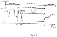
- Figure 1 shows a dependence of the engine speed on the time or an event. Up to the point in time or event ⁇ 1 ⁇ , the implement is operated in load operation, a maximum engine speed (MAX) not being exceeded. The speed fluctuates in load operation depending on the load requirement, like this Figure 1 can be seen.
- MAX maximum engine speed
- the idle operation of the implement begins at the time ⁇ 1 ⁇ , with a first conventional idle speed in the period up to the time ⁇ 2 ⁇ is set, which is within an approved or certified speed range.
- the idle speed is reduced like this Figure 1 can be seen, namely to a value that is lower than the lower limit of the certified speed range.
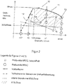
- Figure 2 and Figure 3 show the dependence of the torque of the internal combustion engine on the speed.
- the certified speed band or the certified speed range lies between n 0 and n max .
- the bold line with the reference symbol 11, 21 denotes the full load curve or the maximum torque curve over the speed in the certified work band and the bold dashed line with the reference symbol 12, 22 denotes the full load curve in the area of the speed reduction.
- the thin dashed line with the reference number 16, 26 identifies the lower limit curve of the NTE zone, the NTE zone being the non-to-exceed zone within which certain pollutant values must not be exceeded.
- the NTE zone ie the hatched area with the reference symbol 17, 27 up through the full load curve 11, 21 down through the lower limit curve 16, 26 and to the right and left through the limit values and the upper limit value 15% n max of the certified speed range limited.
- Reference points 13, 23 identify test points of the non-road steady cycle (NRSC). These operating points shown as circles are thus exemplary operating points of this test cycle. As stated above, for this test cycle or for comparing the emissions at idle speed, operating point 8 of the static C1 test according to ISO 8178/4.
- the square dots with the reference numerals 14, 24 indicate test points of the NRTC, i. H. of the non-road transient cycle. Like the test points of the NRSC, these are also exemplary.
- the NTE zone within which the legally emitted pollutant values, e.g. for NOx, PM and HC, must not be exceeded, is limited by 15% n max and upwards by n max .
- the pollutant limit values may be exceeded.
- the certified speed band is not stretched, but operating points outside the certified speed band are controlled when certain conditions are met.
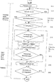
- Figure 4 shows an example of a method according to the invention, in which it is determined in step 2.1 whether the internal combustion engine or the diesel engine is running. If this is the case, it is checked whether the idle mode is recognized (step 2.2). If this is not the case, the test is repeated. If this is the case, it is checked in step 2.3 whether the sleep mode is inactive. If this is not the case, continue with step 2.10.
- step 2.4 If the sleep mode is inactive, it is checked whether the time period t1 within which the idle mode is operating exceeds a threshold value (step 2.4). If this is not the case, the test is repeated, but if this is the case, it is checked whether there are restrictions on the vehicle (step 2.5).
- the responsibility of whether the minimum duration t1 is met lies with the vehicle manufacturer and is controlled via the vehicle control computer.
- the vehicle control unit checks whether there are no further vehicle-side restrictions against lowering after the lapse of the time period t1 in idle mode (step 2.5) and in the event that there are no vehicle-side restrictions, the parking brake is applied (step 2.5.1). If such restrictions exist, the test is repeated, if they do not exist, the signal or the specification for the reduced idling speed, for example 400 rpm, which is outside the certification speed range, is sent to the engine or the engine control unit (step 2.6).
- the engine or engine control unit is sent the instruction to reduce the idle speed.
- the reduced idle speed is in any case outside the certification speed band and is according to Figure 1 approached between points ⁇ 2 ⁇ and ⁇ 3 ⁇ .
- vehicle-side restrictions which are not mandatory, however, are the electrical energy requirement, the state of charge of the battery, operating temperatures and air conditioning system operation.
- the engine or the engine control unit first checks whether there are no engine-side restrictions against lowering (step 2.7). If such restrictions exist, the check is repeated, if not, the engine speed is reduced (step 2.8).
- Such restrictions can be, for example, but not necessarily, the coolant temperature, the temperature level of the exhaust gas aftertreatment and the oil pressure.
- step 2.9 the speed is reduced to the specification of the vehicle control computer (step 2.9) and the vehicle switches to sleep mode according to step 2.10. This is obtained immediately, bypassing the steps mentioned, if the condition ("NO") has already been recognized in test step 2.3, i. H. sleep mode is active.
- step 2.9 If the engine speed is not reduced in step 2.9, the method returns to step 2.5.
- step 2.12 If the vehicle now requests a load in accordance with step 2.12, the engine speed is increased in accordance with step 2.14 until the conventional idling speed has been reached in accordance with step 2.15, ie a speed within the certified speed range. This corresponds to point ⁇ 3 ⁇ in Figure 1 . Only then is the parking brake released in accordance with step 2.16.1 and the motor may be loaded in accordance with step 2.16. If there is no load request from the vehicle, there are engine-side restrictions, such as too low a coolant temperature, and / or vehicle-side restrictions (step 2.12.1), the engine speed is also increased and an engine load only takes place in this case if one Idle speed in the certified speed range is reached.
- step 2.15 ie a speed within the certified speed range. This corresponds to point ⁇ 3 ⁇ in Figure 1 . Only then is the parking brake released in accordance with step 2.16.1 and the motor may be loaded in accordance with step 2.16. If there is no load request from the vehicle, there are engine-side restrictions,
- step 2.17 ends in step 2.17 or is repeated in step 2.1.
- step 2.13 the engine speed is not increased if there is neither a load request from the vehicle nor vehicle (Step 2.12.1) and / or engine restrictions. If it is determined that there is no load request from the vehicle, there are still restrictions on the vehicle side or restrictions on the engine side, the method returns from step 2.13 to step 2.12, i.e. to check whether there is a load request from the vehicle.
- the present exemplary embodiment relates to a procedure in which the parking brake is closed and in which the parking brake is released after the load request and the increase in the engine speed.
- hydrostatic and power-split drives have the property of self-locking, which counteracts the unwanted movement.
- This property makes it possible to dispense with the activation of the parking brake at the beginning of the lowering and the release of the brake when returning to work, which is a further exemplary embodiment of the invention.
- Using the self-locking of the drive has the advantage of being able to simplify the operating steps in the process of returning to work, i.e. steps 2.5.1 and 2.16.1 can be omitted. It must be assumed that an automatic release of the parking brake by the control system - without the driver's intervention - should be classified as safety-critical, which would require additional manual operating steps, and the driver would consider it disruptive.
- the ability of self-locking depends on the type and design of the gear unit and can therefore vary. If the self-locking ability would not be able to hold the vehicle in any inclined position, it would be necessary to check the pending load at the transmission output before triggering the function, for example by monitoring the pressure in a hydraulic path of the transmission, and with a threshold value to compare to see if the machine could be leaning.
- This comparison would be taken into account as a restriction on the implement or vehicle in the vehicle control, and the change to operation at reduced speed during idling would be suppressed if the load at the transmission output indicates that the vehicle is in an inclined position.
- the result of this comparison can therefore also count among the vehicle-side restrictions, which are mentioned by way of example in step 2.5.
Landscapes
- Engineering & Computer Science (AREA)
- Chemical & Material Sciences (AREA)
- Combustion & Propulsion (AREA)
- Mechanical Engineering (AREA)
- General Engineering & Computer Science (AREA)
- Control Of Vehicle Engines Or Engines For Specific Uses (AREA)
- Combined Controls Of Internal Combustion Engines (AREA)
- Operation Control Of Excavators (AREA)
Description
- Die vorliegende Erfindung betrifft ein Verfahren zur Steuerung eines Arbeitsgerätes, insbesondere eines mobilen Arbeitsgerätes und vorzugsweise eines Radladers, wobei das Arbeitsgerät wenigstens einen Verbrennungsmotor aufweist, der in zumindest einem Leerlaufmodus betreibbar ist.
- Aus dem Stand der Technik ist es bekannt, die Drehzahl des Verbrennungsmotors einer mobilen Arbeitsmaschine im Leerlauf soweit wie möglich abzusenken, mit dem Ziel, den Kraftstoffverbrauch zu senken sowie den Schadstoffausstoß sowie die Abgabe von Schallemissionen zu verringern. Das dabei erreichte Drehzahlniveau ist zur Zeit motorseitig durch die untere Grenze des durch den Gesetzgeber zugelassenen, d. h. zertifizierten Drehzahlbandes beschränkt. Ein typischer Wert für dieses Mindestdrehzahlniveau liegt bei 600 U/min.
- Aus der
DE 10 2010 051 963 A1 ist ein Verfahren zum Betrieb eines Arbeitsgerätes bekannt, bei dem der Verbrennungsmotor in einem Leerlaufbetriebsmodus betrieben wird und in weitere Energiesparmodi versetzt wird, wobei die Zeitspanne, für die der Verbrennungsmotor in dem Leerlaufbetriebsmodus betrieben wird, bevor in den weiteren Energiesparmodus gewechselt wird, auf der Grundlage der Auswertungen der Betriebshistorie des Arbeitsgerätes bestimmt wird. - Eine Möglichkeit, den Motor im Leerlauf bei geringerer Drehzahl zu betreiben, besteht darin, die Mindestdrehzahl des genannten zugelassenen, d. h. zertifizierten Arbeitsdrehzahlbandes nach unten zu schieben, mit anderen Worten, das Drehzahlband zu kleineren Werten der Drehzahl hin zu erweitern. Diese Erweiterung bringt jedoch den Nachteil mit sich, dass Drehzahlbereiche erschlossen werden müssen, die im Betrieb gar nicht benötigt werden. Dadurch ergeben sich je nach Fahrzeuganwendung Schwierigkeiten und Nachteile, wie Emissionsgrenzwerte bei gleichzeitig möglichst geringem Kraftstoffgebrauch einzuhalten, da das Drehzahlband in diesem Fall gestreckt, d. h. zu kleineren Drehzahlen hin erweitert würde. Dies hätte zur Folge, dass sich Prüfpunkte in Bereiche geringerer Drehzahlen verlagern, die praktisch jedoch nicht auftreten und daher an sich nicht von Relevanz sind.
- Der vorliegenden Erfindung liegt die Aufgabe zugrunde, ein Verfahren der eingangs genannten Art dahingehend weiterzubilden, dass die mit einer Streckung des zertifizierten Arbeitsdrehzahlbandes verbundenen Nachteile nicht auftreten und dennoch eine Senkung des Schadstoffausstoßes sowie der Schallemissionen und auch des Kraftstoffverbrauchs erzielt werden kann.
- Diese Aufgabe wird durch ein Verfahren mit den Merkmalen des Anspruchs 1 gelöst. Danach ist vorgesehen, dass das Verfahren den Schritt der Absenkung der Motordrehzahl im Leerlauf unter die Mindestdrehzahl eines zertifizierten Drehzahlbandes umfasst, wenn wenigstens eine Bedingung erfüllt ist. Erfindungsgemäß ist somit vorgesehen, ein Kraftstoffeinsparungspotential sowie eine Verringerung des Schadstoffausstoßes sowie der Schallemissionen dadurch zu erreichen, dass der Motor weiterhin im üblichen Drehzahlband zertifiziert wird und dass bei Vorliegen wenigstens einer Bedingung in einen Leerlaufbetriebspunkt gewechselt wird, dessen Drehzahl außerhalb des Zertifizierungsbandes liegt und der vorzugsweise deutlich unterhalb der minimalen Zertifizierungsdrehzahl, d. h. unterhalb der geringsten Drehzahl des zertifizierten Arbeitsdrehzahlbandes liegt.
- Das erfindungsgemäße Verfahren ermöglicht es somit, den Verbrennungsmotor eines Arbeitsgerätes im Leerlauf außerhalb des zertifizierten Arbeitsdrehzahlbandes zu betreiben, und zwar vorzugsweise bei einer weit geringeren Drehzahl als üblich und trotzdem bzw. gerade deshalb die gesetzlichen Emissionsziele einhalten oder sogar unterschreiten zu können.
- Bei der genannten Bedingung handelt es sich um eine Zeitspanne handeln, mit der der Motor im Leerlauf innerhalb des zertifizierten Arbeitsbandes läuft. Diese Zeitspanne, d. h. die Vorlaufzeit wird so gewählt, dass diese zumindest der am längsten dauernden Leerlaufphase im dynamischen Prüfzyklus nach ISO 8178/11 entspricht, so dass das erfindungsgemäße Verfahren während des Prüfzyklus nicht zur Anwendung kommt.
- Bei dem genannten Zyklus handelt es sich um den sogenannten Non-Road-Transient-Cycle (NRTC).
- Gleichzeitig wird jedoch sichergestellt und durch den Motorhersteller bestätigt, dass die Emissionen im Leerlauf außerhalb des Zertifizierungsbandes keinesfalls höher sind als die innerhalb des Zertifizierungsbandes. Als Grundlage für diesen Vergleich bei Leerlaufdrehzahl kann beispielsweise der Betriebspunkt 8 des statischen C1-Tests nach ISO 8178/4 herangezogen werden. Bei diesem Zyklus handelt es sich um den sogenannten Non-Road-Steady-Cycle (NRSC).
- Wie oben ausgeführt, kann durch die Reduzierung der Leerlaufdrehzahl gemäß dem erfindungsgemäßen Verfahren ein Verbrauchsvorteil erzielt werden. Des Weiteren kann davon ausgegangen werden, dass sich zusätzlich zum Verbrauchsvorteil auch eine Reduzierung der Emissionen erzielen lässt, womit das erfindungsgemäße Verfahren der Umwelt hinsichtlich Resourcenschonung und Luftverschmutzung zugute kommt.
- In weiterer Ausgestaltung der Erfindung wird die Einhaltung der genannten Zeitspanne, d. h. der Vorlaufzeit, nach der erst eine Drehzahl außerhalb des zertifizierten Arbeitsbandes eingestellt werden kann, durch einen Leitrechner des Arbeitsgerätes sichergestellt.
- Als zusätzliche Bedingung kann das Fehlen einer oder mehrerer arbeitsgeräteseitiger Einschränkungen herangezogen werden. In diesem Fall prüft beispielsweise ein Steuergerät, ob nach Verstreichen der genannten Zeitspanne im Leerlauf keine weiteren, arbeitsgeräteseitige bzw. fahrzeugseitige Einschränkungen gegen die Absenkung der Drehzahl sprechen. Exemplarisch für solche Einschränkungen sind der elektrische Energiebedarf und/oder der Ladezustand der Batterie und/oder Betriebstemperaturen und/oder der Klimaanlagenbetrieb. Ist beispielsweise der Ladezustand der Batterie nicht ausreichend, kann festgestellt werden, dass trotz Verstreichen der Zeitspanne eine Absenkung der Motordrehzahl unter die Mindestdrehzahl des zertifizierten Arbeitsbandes nicht erfolgt. Ein weiteres Beispiel für eine arbeitsgeräteseitige bzw. fahrzeugseitige Einschränkung ist die Last am Getriebeausgang und insbesondere der Druck in einem hydraulischen Pfad des Getriebes. Durch einen Vergleich der Last bzw. des Drucks und einem Schwellenwert kann ermittelt werden, ob sich das Fahrzeug in einer Schräglage befindet. Ist dies der Fall, kann vorgesehen sein, dass der Wechsel in den Betrieb mit reduzierter Drehzahl unterbunden wird.
- Weiterhin kann als zusätzlcihe Bedingung das Fehlen einer oder mehrerer motorseitiger Einschränkungen herangezogen werden. Solche motorseitigen Einschränkungen können die Kühlmitteltemperatur und/oder die Temperatur einer Abgasbehandlungsanlage und/oder der Öldruck sein. Auch diese Parameter sind exemplarischer Natur und nicht beschränkend.
- Vorzugsweise ist vorgesehen, dass die erfindungsgemäße Absenkung der Motordrehzahl erst dann vorgenommen wird, wenn die Zeitspanne, mit der der Motor im Leerlauf innerhalb des zertifizierten Arbeitsbandes läuft, verstrichen ist und wenn zusätzlich weder arbeitsgeräteseitige noch motorseitige Einschränkungen vorliegen. In diesem Fall sind somit zumindest drei Bedingungen zu erfüllen, bevor ein Absenken der Motordrehzahl im Leerlauf erfolgen kann.
- In weiterer Ausgestaltung der Erfindung ist vorgesehen, dass nach einer Lastanforderung eine Belastung des Motors erst dann erfolgt, wenn die Motordrehzahl in dem zertifizierten Arbeitsband liegt. In diesem Fall erfolgt das neuerliche Anheben der Motordrehzahl ohne Last. Während des aktiven Leerlaufmodus wird somit bei abgesenkter Drehzahl fahrzeugseitig dafür gesorgt, dass der Motor keine Lastsprünge sieht, wodurch dieser abgewürgt werden könnte.
- Die vorliegende Erfindung betrifft des Weiteren ein Arbeitsgerät, insbesondere ein mobiles Arbeitsgerät und vorzugsweise einen Radlader, mit wenigstens einem Verbrennungsmotor und mit wenigstens einer Steuerungs- oder Regelungseinheit, wobei die Steuerungs- oder Regelungseinheit derart ausgebildet ist, dass sie das Verfahren gemäß einem der Ansprüche 1 bis 10 durchführt.
- Weitere Einzelheiten und Vorteile der Erfindung werden anhand eines in der Zeichnung dargestellten Ausführungsbeispiels näher erläutert. Es zeigen:
- Figur 1:
- der zeitliche Verlauf der Motordrehzahl bei Anwendung des erfindungsgemäßen Verfahrens,
- Figur 2:
- eine schematische Darstellung der Abhängigkeit des Drehmomentes von der Drehzahl sowie der NTE-Zone,
- Figur 3:
- eine Darstellung gemäß
Figur 2 mit verschobenen unterem Grenzwert für die NTE-Zone, - Figur 4:
- ein Fließbild, das exemplarisch die Durchführung des erfindungsgemäßen Verfahrens beschreibt.
-
Figur 1 zeigt eine Abhängigkeit der Motordrehzahl von der Zeit bzw. von einem Ereignis. Bis zu dem Zeitpunkt bzw. Ereignis {1} wird das Arbeitsgerät im Lastbetrieb betrieben, wobei eine maximale Motordrehzahl (MAX) nicht überschritten wird. Die Drehzahl schwankt im Lastbetrieb je nach Lastanforderung, wie dies ausFigur 1 ersichtlich ist. - Zu dem Zeitpunkt {1} beginnt der Leerlaufbetrieb des Arbeitsgerätes, wobei in der Zeitspanne bis zu dem Zeitpunkt {2} eine erste konventionelle Leerlaufdrehzahl eingestellt wird, die innerhalb eines zugelassenen bzw. zertifizierten Drehzahlbandes liegt. Zu dem Zeitpunkt {2} wird die Leerlaufdrehzahl reduziert, wie dies aus
Figur 1 ersichtlich ist, und zwar auf einen Wert, der geringer ist als der untere Grenzwert des zertifizierten Drehzahlbereiches. - Zu dem Zeitpunkt {3} wird der Leerlaufbetrieb beendet und ein erneuter Lastbetrieb aufgenommen, wobei wie aus
Figur 1 ersichtlich zu Beginn des Lastbetriebes die Drehzahl wieder auf die konventionelle Drehzahl angehoben wird, und zwar bevor der Lastbetrieb beginnt. -
Figur 2 undFigur 3 zeigen die Abhängigkeit des Drehmomentes des Verbrennungsmotors von der Drehzahl. - Das zertifizierte Drehzahlband bzw. der zertifizierte Drehzahlbereich liegt in dem hier dargestellten Ausführungsbeispiel zwischen n0 und nmax. Die fette Linie mit dem Bezugszeichen 11, 21 kennzeichnet die Volllastkurve bzw. den Maximalmomentenverlauf über die Drehzahl im zertifizierten Arbeitsband und die fette gestrichelte Linie mit dem Bezugszeichen 12, 22 kennzeichnet die Volllastkurve im Bereich der Drehzahlabsenkung.
- Die dünne gestrichelte Linie mit dem Bezugszeichen 16, 26 kennzeichnet die untere Grenzkurve der NTE-Zone, wobei es sich bei der NTE-Zone um die Non-to-Exceed-Zone handelt, innerhalb derer bestimmte Schadstoffwerte nicht überschritten werden dürfen. Wie dies aus
Figur 2 hervorgeht, wird die NTE-Zone, d. h. der schraffierte Bereich mit dem Bezugszeichen 17, 27 nach oben durch die Volllastkurve 11, 21 nach unten durch die untere Grenzkurve 16, 26 und nach rechts und links durch die Grenzwerte und den oberen Grenzwert 15%nmax des zertifizierten Drehzahlbandes begrenzt. - Mit dem Bezugszeichen 13, 23 sind Prüfpunkte des Non-Road-Steady-Cycle (NRSC) gekennzeichnet. Diese als Kreise dargestellten Betriebspunkte sind somit exemplarische Betriebspunkte dieses Prüfzyklus. Wie oben ausgeführt, werden für diesen Prüfzyklus bzw. für den Vergleich der Emissionen bei Leerlaufdrehzahl der Betriebspunkt 8 des statischen C1-Tests nach ISO 8178/4 herangezogen.
- Die weiteren runden Punkte kennzeichnen weitere Prüfpunkte dieses Prüfzyklus.
- Die eckigen Punkte mit dem Bezugszeichen 14, 24 kennzeichnen Prüfpunkte des NRTC, d. h. des Non-Road-Transient-Cycle. Auch diese sind wie auch die Prüfpunkte des NRSC beispielhaft.
- Wie dies aus
Figur 2 hervorgeht, wird die NTE-Zone, innerhalb der gesetzliche emittierte Schadstoffwerte, beispielsweise für NOx, PM und HC nicht überschritten werden dürfen, nach unten durch 15%nmax und nach oben durch nmax begrenzt. Der Wert 15%nmax ist definiert aus n0, d. h. der untersten Drehzahl des zertifizierten Arbeitsbandes und einem Zuschlag von 15 % der Breite des Arbeitsbandes, d. h.

- Außerhalb des schraffierten Bereiches, d. h. bei Drehzahlwerten·< 15%nmax ist eine Überschreitung der Schadstoffgrenzwerte zulässig.
- Dies gilt beispielsweise für den Bereich 15 gemäß
Figur 2 und 25 gemäßFigur 3 . - Würde nun die untere Drehzahl des zertifizierten Arbeitsbandes von n0 auf n01 abgesenkt, hätte dies zur Folge, dass der Wert 15%nmax ebenfalls nach links verschoben wird, wie dies aus
Figur 3 hervorgeht. Daraus ergibt sich eine Verbreiterung der NTE-Zone, beispielsweise im Drehzahlband zwischen 400 U/min - 2200 U/min. Aus diesem Grund würden sich Betriebspunkte des NRTC-Tests wie ausFigur 3 ersichtlich in Richtung der Abszisse zu geringeren Drehzahlen hin ausdehnen bzw. es ergäbe sich eine ungünstige Verschiebung der Bereiche 15, 25 und 17, 27. - Um die damit verbundenen Nachteile zu vermeiden, wird erfindungsgemäß nicht das zertifizierte Drehzahlband gedehnt, sondern es werden Betriebspunkte außerhalb des zertifizierten Drehzahlbandes angesteuert, wenn bestimmte Bedingungen erfüllt sind.
-
Figur 4 zeigt exemplarisch ein erfindungsgemäßes Verfahren, bei dem in Schritt 2.1 ermittelt wird, ob der Verbrennungsmotor bzw. der Dieselmotor läuft. Ist dies der Fall, wird geprüft, ob der Leerlaufmodus erkannt wird (Schritt 2.2). Ist dies nicht der Fall, wird die Prüfung wiederholt, ist dies der Fall, wird in Schritt 2.3 überprüft, ob der Schlafmodus inaktiv ist. Ist dies nicht der Fall, wird mit Schritt 2.10 fortgefahren. - Ist der Schlafmodus inaktiv, wird überprüft, ob die Zeitspanne t1, innerhalb der Leerlaufmodus in Betrieb ist, einen Schwellwert überschreitet (Schritt 2.4). Ist dies nicht der Fall, wird die Prüfung wiederholt, ist dies jedoch der Fall, wird überprüft, ob fahrzeugseitige Einschränkungen vorliegen (Schritt 2.5).
- Die Verantwortung, ob die Mindestdauer t1 eingehalten wird, liegt beim Fahrzeughersteller und wird über den Fahrzeugleitrechner gesteuert.
- Das Fahrzeugsteuergerät überprüft, ob nach Verstreichen der Zeitdauer t1 im Leerlauf keine weiteren, fahrzeugseitigen Einschränkungen gegen das Absenken sprechen (Schritt 2.5) und für den Fall, dass keine fahrzeugseitigen Einschränkungen vorliegen, wir die Parkbremse geschlossen (Schritt 2.5.1). Liegen solche Einschränkungen vor, wird die Prüfung wiederholt, liegen sie nicht vor, wird dem Motor bzw. dem Motorsteuergerät das Signal bzw. die Vorgabe für die abgesenkte Leerlaufdrehzahl, beispielsweise 400 U/min gesendet, die außerhalb des Zertifizierungsdrehzahlbandes liegt (Schritt 2.6).
- In diesem Schritt wird dem Motor bzw. Motorsteuergerät die Vorgabe gesendet, die Leerlaufdrehzahl abzusenken. Die abgesenkte Leerlaufdrehzahl liegt jedenfalls außerhalb des Zertifizierungsdrehzahlbandes und wird gemäß
Figur 1 zwischen den Punkten {2} und {3} angefahren. - Exemplarisch für fahrzeugseitige Einschränkungen, die jedoch nicht zwingend sind, sind der elektrische Energiebedarf, der Ladezustand der Batterie, Betriebstemperaturen und Klimaanlagenbetrieb.
- In weiterer Folge überprüft der Motor bzw. das Motorsteuergerät zunächst, ob keine motorseitigen Einschränkungen gegen das Absenken sprechen (Schritt 2.7). Liegen solche Einschränkungen vor, wird die Überprüfung wiederholt, wenn nicht, wird die Motordrehzahl abgesenkt (Schritt 2.8).
- Solche Einschränkungen können beispielsweise, aber nicht zwingend die Kühlmitteltemperatur, das Temperaturniveau der Abgasnachbehandlung und der Öldruck sein.
- Liegen solche motorseitigen Einschränkungen nicht vor, wird die Drehzahl auf den Vorgabewunsch des Fahrzeugleitrechners reduziert (Schritt 2.9) und das Fahrzeug wechselt gemäß Schritt 2.10 in den Schlafmodus. Dieser wird unter Umgehung der genannten Schritte sofort erhalten, wenn in Prüfungsschritt 2.3 bereits die Bedingung ("NEIN") erkannt wurde, d. h. der Schlafmodus aktiv ist.
- Wird die Motordrehzahl in Schritt 2.9 nicht abgesenkt, kehrt das Verfahren zurück zu Schritt 2.5.
- In jedem Falle wird während dieses Schlafmodus, d. h. während des Leerlaufbetriebes außerhalb des Zertifizierungsbandes der Motor gemäß Schritt 2.11 nicht übermäßig belastet, um das Abwürgen zu verhindern. In diesem Betriebsbereich kann eine Leistungsbereitstellung nur in eingeschränktem Umfang erfolgen, wie beispielsweise für untergeordnete Verbraucher wie Klimakompressor und/oder die Lichtmaschine. Als nicht untergeordnete Verbraucher sind beispielsweise der Fahrantrieb, Arbeits- und Lenkhydraulik anzuführen, deren Leistungsanforderung unterbunden werden.
- Erfolgt nun eine Lastanforderung durch das Fahrzeug gemäß Schritt 2.12, wird gemäß Schritt 2.14 die Motordrehzahl angehoben, und zwar solange bis gemäß Schritt 2.15 die konventionelle Leerlaufdrehzahl erreicht ist, d. h. eine Drehzahl innerhalb des zertifizierten Drehzahlbandes. Dies entspricht Punkt {3} in
Figur 1 . Erst dann wird gemäß Schritt 2.16.1 die Parkbremse gelöst und es darf gemäß Schritt 2.16 der Motor belastet werden. Liegt keine Lastanforderung durch das Fahrzeug vor, liegen jedoch motorseitige Einschränkungen vor, wie beispielsweise eine zu geringe Kühlmitteltemperatur, und/oder fahrzeugseitige Einschränkungen (Schritt 2.12.1) wird ebenfalls die Motordrehzahl angehoben und eine Motorbelastung erfolgt aber auch in diesem Fall erst, wenn eine Leerlaufdrehzahl im zertifizierten Drehzahlband erreicht ist. - Das Verfahren endet in Schritt 2.17 bzw. wird in Schritt 2.1 erneut durchlaufen.
- Wie dies aus Schritt 2.13 hervorgeht, unterbleibt das Anheben der Motordrehzahl, wenn weder eine Lastanforderung durch das Fahrzeug vorliegt noch fahrzeug-(Schritt 2.12.1) und/oder motorseitige Einschränkungen bestehen. Wird festgestellt, dass keine Lastanforderung durch das Fahrzeug besteht, noch fahrzeugseitige Einschränkungen noch motorseitige Einschränkungen vorliegen, kehrt das Verfahren von Schritt 2.13 zurück zu Schritt 2.12, d.h. zu der Prüfung, ob eine Lastanforderung durch das Fahrzeug vorliegt.
- Wie oben ausgeführt, betrifft das vorliegende Ausführungsbeispiel eine Vorgehensweise, bei der die Parkbremse geschlossen wird und bei der nach der Lastanforderung und der Anhebung der Motordrehzahl die Parkbremse gelöst wird.
- Bei Fahrzeugen bzw. Arbeitsgeräten mit hydrodynamischem Antrieb ist es zwangsläufig erforderlich, die Parkbremse im Stillstand zu aktivieren, um ein ungewolltes
- Losrollen des Fahrzeuges unterbinden zu können. Hingegen weisen hydrostatische und leistungsverzweigte Antriebe die Eigenschaft einer Selbsthemmung auf, die dem ungewollten in Bewegung setzen entgegen wirkt.
- Diese Eigenschaft erlaubt es, auf das Aktivieren der Parkbremse zu Beginn des Absenkens, und das Lösen der Bremse beim Zurückkehren in den Arbeitsbetrieb verzichten zu können, was ein weiteres Ausführungsbeispiel der Erfindung darstellt. Das Nützen der Selbsthemmung des Antriebes weist den Vorteil auf, die Bedienschritte im Ablauf des Zurückkehrens in den Arbeitsbetrieb vereinfachen zu können, d.h. die Schritte 2.5.1 und 2.16.1 können entfallen. Es muss davon ausgegangen werden, dass ein automatisches Lösen der Parkbremse durch die Steuerung - ohne Zutun des Fahrers - als sicherheitskritisch einzustufen sein dürfte, was zusätzliche manuellen Bedienschritte erfordern würde, und der Fahrer als störend beurteilen würde.
- Das Vermögen der Selbsthemmung ist abhängig von Getriebetyp und -ausführung und kann daher variieren. Sofern das Selbsthemmungsvermögen nicht in der Lage wäre, das Fahrzeug in beliebiger Schräglage zu halten, wäre es erforderlich, vor dem Auslösen der Funktion die anstehende Last am Getriebeausgang zu prüfen, beispielweise durch Überwachung des Druckes in einem hydraulischen Pfad des Getriebes, und mit einem Schwellwert zu vergleichen, um feststellen zu können, ob sich die Maschine in Schräglage befinden könnte.
- Es würde dieser Vergleich als arbeitsgerätseitige bzw. fahrzeugseitige Einschränkung in der Fahrzeugsteuerung berücksichtigt werden, und das Wechseln in den Betrieb mit reduzierter Drehzahl im Leerlauf unterdrückt werden, falls die Last am Getriebeausgang darauf hindeutet, dass sich das Fahrzeug in Schräglage befindet. Zu den fahrzeugseitigen Einschränkungen, die exemplarisch in Schritt 2.5 genannt sind, kann somit auch das Ergebnis dieses Vergleiches zählen.
Claims (9)
- Verfahren zur Steuerung eines Arbeitsgerätes, insbesondere eines mobilen Arbeitsgerätes und vorzugsweise eines Radladers, wobei das Arbeitsgerät wenigstens einen Verbrennungsmotor aufweist, der in zumindest einem Leerlaufmodus betreibbar ist, und wobei das Verfahren den Schritt der Absenkung der Motordrehzahl im Leerlauf unter die Mindestdrehzahl eines zertifizierten Drehzahlbandes umfasst, wenn wenigstens eine Bedingung erfüllt ist,
dadurch gekennzeichnet,
dass es sich bei der Bedingung um den Ablauf einer Zeitspanne handelt, mit der der Motor im Leerlauf innerhalb des zertifizierten Drehzahlbandes läuft, wobei die Zeitspanne zumindest der am längsten dauernden Leerlaufphase in dem dynamischen Prüfzyklus ISO 8178/11 entspricht. - Verfahren nach Anspruch 1, dadurch gekennzeichnet, dass die Einhaltung der Zeitspanne durch einen Leitrechner des Arbeitsgerätes sichergestellt wird.
- Verfahren nach einem der vorhergehenden Ansprüche, dadurch gekennzeichnet, dass es sich bei einer weiteren Bedingung um das Fehlen einer oder mehrerer arbeitsgeräteseitiger Einschränkungen handelt.
- Verfahren nach Anspruch 3, dadurch gekennzeichnet, dass die arbeitsgeräteseitigen Einschränkungen der elektrische Energiebedarf und/oder der Ladezustand der Batterie und/oder eine oder mehrere Betriebstemperaturen und/oder der Klimaanlagenbetrieb und/oder die anstehende Last am Getriebeausgang, vorzugsweise der Druck in einem hydraulischen Pfad des Getriebes sind.
- Verfahren nach einem der vorhergehenden Ansprüche, dadurch gekennzeichnet, dass es sich bei einer weiteren Bedingung um das Fehlen einer oder mehrerer motorseitiger Einschränkungen handelt.
- Verfahren nach Anspruch 5, dadurch gekennzeichnet, dass die motorseitigen Einschränkungen die Kühlmitteltemperatur und/oder die Temperatur einer Abgasbehandlungsanlage und/oder der Öldruck sind.
- Verfahren nach einem der vorhergehenden Ansprüche, dadurch gekennzeichnet, dass die Absenkung der Motordrehzahl erst dann vorgenommen wird, wenn die Zeitspanne, mit der der Motor im Leerlauf innerhalb des zertifizierten Arbeitsbandes läuft, verstrichen ist und wenn weder arbeitsgeräteseitige noch motorseitige Einschränkungen vorliegen.
- Verfahren nach einem der vorhergehenden Ansprüche, dadurch gekennzeichnet, dass nach einer Lastanforderung eine Belastung des Motors erst dann erfolgt, wenn die Motordrehzahl in dem zertifizierten Arbeitsband liegt.
- Arbeitsgerät, insbesondere mobiles Arbeitsgerät und vorzugsweise Radlader, mit wenigstens einem Verbrennungsmotor und mit wenigstens einer Steuerungs- oder Regelungseinheit, dadurch gekennzeichnet, dass die Steuerungs- oder Regelungseinheit derart ausgebildet ist, dass sie das Verfahren gemäß einem der Ansprüche 1 bis 8 durchführt.
Applications Claiming Priority (1)
| Application Number | Priority Date | Filing Date | Title |
|---|---|---|---|
| DE102013006074 | 2013-04-08 |
Publications (3)
| Publication Number | Publication Date |
|---|---|
| EP2789835A2 EP2789835A2 (de) | 2014-10-15 |
| EP2789835A3 EP2789835A3 (de) | 2014-12-10 |
| EP2789835B1 true EP2789835B1 (de) | 2020-04-29 |
Family
ID=50391073
Family Applications (1)
| Application Number | Title | Priority Date | Filing Date |
|---|---|---|---|
| EP14162709.1A Active EP2789835B1 (de) | 2013-04-08 | 2014-03-31 | Verfahren zur Steuerung eines Arbeitsgerätes |
Country Status (2)
| Country | Link |
|---|---|
| EP (1) | EP2789835B1 (de) |
| DE (1) | DE102014004689A1 (de) |
Family Cites Families (3)
| Publication number | Priority date | Publication date | Assignee | Title |
|---|---|---|---|---|
| DE102004044473B4 (de) * | 2004-09-15 | 2007-12-20 | Bayerische Motoren Werke Ag | Steuereinheit und Verfahren zur Ansteuerung der Antriebseinheit eines Kraftfahrzeugs |
| DE102010047628B4 (de) * | 2010-09-28 | 2020-06-18 | Linde Material Handling Gmbh | Antriebsstrang einer mobilen Arbeitsmaschine |
| DE102010051963B4 (de) | 2010-11-19 | 2015-08-20 | Liebherr-Werk Bischofshofen Gmbh | Verfahren zum Betrieb eines Arbeitsgerätes, Arbeitsgerät und Steuerung für ein Arbeitsgerät |
-
2014
- 2014-03-31 DE DE102014004689.3A patent/DE102014004689A1/de not_active Withdrawn
- 2014-03-31 EP EP14162709.1A patent/EP2789835B1/de active Active
Non-Patent Citations (1)
| Title |
|---|
| None * |
Also Published As
| Publication number | Publication date |
|---|---|
| DE102014004689A1 (de) | 2014-10-09 |
| EP2789835A2 (de) | 2014-10-15 |
| EP2789835A3 (de) | 2014-12-10 |
Similar Documents
| Publication | Publication Date | Title |
|---|---|---|
| DE112011102914B4 (de) | Steuerung zur Regeneration einer Nachbehandlungseinrichtung in einem Fahrzeug mit Hybridantrieb | |
| EP2999904B1 (de) | Verfahren für ein hydrauliksystem für ein doppelkupplungsgetriebe | |
| DE102007056282A1 (de) | Verfahren zum Steuern eines Leerlauf-Stopp-Modus in einem Hybridelektrofahrzeug | |
| DE112014005144B4 (de) | Steuervorrichtung für ein Fahrzeug | |
| DE102011087016A1 (de) | Vorrichtung zur Steuerung eines Kraftfahrzeug-Antriebsstranges | |
| EP2334531B1 (de) | Verfahren zum betreiben eines fahrzeugs mit einem hybriden motorsystem sowie motorsystem und fahrzeug | |
| DE102013205315A1 (de) | Verfahren zum Erzeugen einer Steuerausgabe aus einem Kupplungspositionserfassungssystem eines Kraftfahrzeugs | |
| EP3608185B1 (de) | Verfahren zum betreiben einer hybridantriebseinrichtung für ein kraftfahrzeug sowie entsprechende hybridantriebseinrichtung | |
| DE102017108718B4 (de) | Verfahren zum betreiben eines automatischen start/stopp-systems in einem fahrzeug mit nasser anfahrkupplung | |
| DE10328786B4 (de) | Verfahren zum Betreiben eines Kraftfahrzeuges | |
| DE102011108490B4 (de) | Hybridantriebsstrang mit elektronischer Drosselklappe und Verfahren zum Steuern der Drosselklappenposition | |
| DE102006025053A1 (de) | Verfahren zur Steuerung einer Brennkraftmaschine | |
| DE102006001201A1 (de) | Verfahren zur Steuerung eines Batterieladungsvorgangs | |
| DE102008002384A1 (de) | Verfahren zur Grenzlastregelung eines hydrostatischen Antriebs | |
| DE102014002849A1 (de) | Antriebsmaschinensteuerungsvorrichtung | |
| DE102010032087A1 (de) | Verfahren und Vorrichtung zum Stoppen eines Verbrennungsmotors | |
| DE69402532T2 (de) | Verfahren und vorrichtung zur verminderung der schädlichen abgase einer kraftfahrzeug-brennkraftmaschine | |
| DE102007057786B4 (de) | Verfahren zum Betreiben einer Antriebsvorrichtung | |
| DE102012220495A1 (de) | Verfahren zur Verbesserung des Warmlaufs eines Motors | |
| DE102013020658A1 (de) | Betriebsverfahren für eine Kraftfahrzeug-Brennkraftmaschine | |
| DE112019003902T5 (de) | Fahrzeugsteuervorrichtung | |
| DE102016005412A1 (de) | Ein Verfahren zum Starten eines Verbrennungsmotors in einem Parallel-Hybrid- Antriebsstrang, ein Fahrzeug, das einen solchen Hybrid-Antriebsstrang umfasst, ein Computerprogramm zum Starten eines Verbrennungsmotors und ein Computerprogrammprodukt, das einen Programmcode umfasst | |
| DE102010020066A1 (de) | Verfahren zum Betrieb eines automatischen Start-Stopp-Systems und Start-Stopp-System für ein Kraftfahrzeug | |
| DE102010021433A1 (de) | Verringerung des Auftretens von Schaltvorgängen im Zusammenhang mit Hybridfahrzeugen | |
| EP3196447B1 (de) | Verfahren und steuervorrichtung zum betreiben einer antriebsvorrichtung |
Legal Events
| Date | Code | Title | Description |
|---|---|---|---|
| PUAI | Public reference made under article 153(3) epc to a published international application that has entered the european phase |
Free format text: ORIGINAL CODE: 0009012 |
|
| 17P | Request for examination filed |
Effective date: 20140331 |
|
| AK | Designated contracting states |
Kind code of ref document: A2 Designated state(s): AL AT BE BG CH CY CZ DE DK EE ES FI FR GB GR HR HU IE IS IT LI LT LU LV MC MK MT NL NO PL PT RO RS SE SI SK SM TR |
|
| AX | Request for extension of the european patent |
Extension state: BA ME |
|
| PUAL | Search report despatched |
Free format text: ORIGINAL CODE: 0009013 |
|
| AK | Designated contracting states |
Kind code of ref document: A3 Designated state(s): AL AT BE BG CH CY CZ DE DK EE ES FI FR GB GR HR HU IE IS IT LI LT LU LV MC MK MT NL NO PL PT RO RS SE SI SK SM TR |
|
| AX | Request for extension of the european patent |
Extension state: BA ME |
|
| RIC1 | Information provided on ipc code assigned before grant |
Ipc: E02F 9/20 20060101ALI20141104BHEP Ipc: F02D 41/02 20060101ALI20141104BHEP Ipc: E02F 1/00 20060101ALI20141104BHEP Ipc: F02D 41/08 20060101AFI20141104BHEP Ipc: F02D 29/00 20060101ALI20141104BHEP |
|
| R17P | Request for examination filed (corrected) |
Effective date: 20150521 |
|
| RIN1 | Information on inventor provided before grant (corrected) |
Inventor name: KNAPP, HANS Inventor name: STOCK, JOSEF Inventor name: KIEGERL, CHRISTOPH |
|
| STAA | Information on the status of an ep patent application or granted ep patent |
Free format text: STATUS: EXAMINATION IS IN PROGRESS |
|
| 17Q | First examination report despatched |
Effective date: 20190711 |
|
| GRAP | Despatch of communication of intention to grant a patent |
Free format text: ORIGINAL CODE: EPIDOSNIGR1 |
|
| STAA | Information on the status of an ep patent application or granted ep patent |
Free format text: STATUS: GRANT OF PATENT IS INTENDED |
|
| INTG | Intention to grant announced |
Effective date: 20191105 |
|
| GRAS | Grant fee paid |
Free format text: ORIGINAL CODE: EPIDOSNIGR3 |
|
| GRAA | (expected) grant |
Free format text: ORIGINAL CODE: 0009210 |
|
| STAA | Information on the status of an ep patent application or granted ep patent |
Free format text: STATUS: THE PATENT HAS BEEN GRANTED |
|
| AK | Designated contracting states |
Kind code of ref document: B1 Designated state(s): AL AT BE BG CH CY CZ DE DK EE ES FI FR GB GR HR HU IE IS IT LI LT LU LV MC MK MT NL NO PL PT RO RS SE SI SK SM TR |
|
| REG | Reference to a national code |
Ref country code: GB Ref legal event code: FG4D Free format text: NOT ENGLISH |
|
| REG | Reference to a national code |
Ref country code: CH Ref legal event code: EP |
|
| REG | Reference to a national code |
Ref country code: CH Ref legal event code: NV Representative=s name: KELLER AND PARTNER PATENTANWAELTE AG, CH Ref country code: AT Ref legal event code: REF Ref document number: 1263681 Country of ref document: AT Kind code of ref document: T Effective date: 20200515 |
|
| REG | Reference to a national code |
Ref country code: DE Ref legal event code: R096 Ref document number: 502014014062 Country of ref document: DE |
|
| REG | Reference to a national code |
Ref country code: IE Ref legal event code: FG4D Free format text: LANGUAGE OF EP DOCUMENT: GERMAN |
|
| REG | Reference to a national code |
Ref country code: CH Ref legal event code: PFA Owner name: LIEBHERR-WERK BISCHOFSHOFEN GMBH, AT Free format text: FORMER OWNER: LIEBHERR-WERK BISCHOFSHOFEN GMBH, AT |
|
| REG | Reference to a national code |
Ref country code: NL Ref legal event code: MP Effective date: 20200429 |
|
| REG | Reference to a national code |
Ref country code: LT Ref legal event code: MG4D |
|
| PG25 | Lapsed in a contracting state [announced via postgrant information from national office to epo] |
Ref country code: LT Free format text: LAPSE BECAUSE OF FAILURE TO SUBMIT A TRANSLATION OF THE DESCRIPTION OR TO PAY THE FEE WITHIN THE PRESCRIBED TIME-LIMIT Effective date: 20200429 Ref country code: PT Free format text: LAPSE BECAUSE OF FAILURE TO SUBMIT A TRANSLATION OF THE DESCRIPTION OR TO PAY THE FEE WITHIN THE PRESCRIBED TIME-LIMIT Effective date: 20200831 Ref country code: GR Free format text: LAPSE BECAUSE OF FAILURE TO SUBMIT A TRANSLATION OF THE DESCRIPTION OR TO PAY THE FEE WITHIN THE PRESCRIBED TIME-LIMIT Effective date: 20200730 Ref country code: FI Free format text: LAPSE BECAUSE OF FAILURE TO SUBMIT A TRANSLATION OF THE DESCRIPTION OR TO PAY THE FEE WITHIN THE PRESCRIBED TIME-LIMIT Effective date: 20200429 Ref country code: NO Free format text: LAPSE BECAUSE OF FAILURE TO SUBMIT A TRANSLATION OF THE DESCRIPTION OR TO PAY THE FEE WITHIN THE PRESCRIBED TIME-LIMIT Effective date: 20200729 Ref country code: SE Free format text: LAPSE BECAUSE OF FAILURE TO SUBMIT A TRANSLATION OF THE DESCRIPTION OR TO PAY THE FEE WITHIN THE PRESCRIBED TIME-LIMIT Effective date: 20200429 Ref country code: IS Free format text: LAPSE BECAUSE OF FAILURE TO SUBMIT A TRANSLATION OF THE DESCRIPTION OR TO PAY THE FEE WITHIN THE PRESCRIBED TIME-LIMIT Effective date: 20200829 |
|
| PG25 | Lapsed in a contracting state [announced via postgrant information from national office to epo] |
Ref country code: RS Free format text: LAPSE BECAUSE OF FAILURE TO SUBMIT A TRANSLATION OF THE DESCRIPTION OR TO PAY THE FEE WITHIN THE PRESCRIBED TIME-LIMIT Effective date: 20200429 Ref country code: HR Free format text: LAPSE BECAUSE OF FAILURE TO SUBMIT A TRANSLATION OF THE DESCRIPTION OR TO PAY THE FEE WITHIN THE PRESCRIBED TIME-LIMIT Effective date: 20200429 Ref country code: BG Free format text: LAPSE BECAUSE OF FAILURE TO SUBMIT A TRANSLATION OF THE DESCRIPTION OR TO PAY THE FEE WITHIN THE PRESCRIBED TIME-LIMIT Effective date: 20200729 Ref country code: LV Free format text: LAPSE BECAUSE OF FAILURE TO SUBMIT A TRANSLATION OF THE DESCRIPTION OR TO PAY THE FEE WITHIN THE PRESCRIBED TIME-LIMIT Effective date: 20200429 |
|
| PG25 | Lapsed in a contracting state [announced via postgrant information from national office to epo] |
Ref country code: AL Free format text: LAPSE BECAUSE OF FAILURE TO SUBMIT A TRANSLATION OF THE DESCRIPTION OR TO PAY THE FEE WITHIN THE PRESCRIBED TIME-LIMIT Effective date: 20200429 Ref country code: NL Free format text: LAPSE BECAUSE OF FAILURE TO SUBMIT A TRANSLATION OF THE DESCRIPTION OR TO PAY THE FEE WITHIN THE PRESCRIBED TIME-LIMIT Effective date: 20200429 |
|
| PG25 | Lapsed in a contracting state [announced via postgrant information from national office to epo] |
Ref country code: RO Free format text: LAPSE BECAUSE OF FAILURE TO SUBMIT A TRANSLATION OF THE DESCRIPTION OR TO PAY THE FEE WITHIN THE PRESCRIBED TIME-LIMIT Effective date: 20200429 Ref country code: CZ Free format text: LAPSE BECAUSE OF FAILURE TO SUBMIT A TRANSLATION OF THE DESCRIPTION OR TO PAY THE FEE WITHIN THE PRESCRIBED TIME-LIMIT Effective date: 20200429 Ref country code: ES Free format text: LAPSE BECAUSE OF FAILURE TO SUBMIT A TRANSLATION OF THE DESCRIPTION OR TO PAY THE FEE WITHIN THE PRESCRIBED TIME-LIMIT Effective date: 20200429 Ref country code: SM Free format text: LAPSE BECAUSE OF FAILURE TO SUBMIT A TRANSLATION OF THE DESCRIPTION OR TO PAY THE FEE WITHIN THE PRESCRIBED TIME-LIMIT Effective date: 20200429 Ref country code: EE Free format text: LAPSE BECAUSE OF FAILURE TO SUBMIT A TRANSLATION OF THE DESCRIPTION OR TO PAY THE FEE WITHIN THE PRESCRIBED TIME-LIMIT Effective date: 20200429 Ref country code: IT Free format text: LAPSE BECAUSE OF FAILURE TO SUBMIT A TRANSLATION OF THE DESCRIPTION OR TO PAY THE FEE WITHIN THE PRESCRIBED TIME-LIMIT Effective date: 20200429 Ref country code: DK Free format text: LAPSE BECAUSE OF FAILURE TO SUBMIT A TRANSLATION OF THE DESCRIPTION OR TO PAY THE FEE WITHIN THE PRESCRIBED TIME-LIMIT Effective date: 20200429 |
|
| REG | Reference to a national code |
Ref country code: DE Ref legal event code: R097 Ref document number: 502014014062 Country of ref document: DE |
|
| PG25 | Lapsed in a contracting state [announced via postgrant information from national office to epo] |
Ref country code: SK Free format text: LAPSE BECAUSE OF FAILURE TO SUBMIT A TRANSLATION OF THE DESCRIPTION OR TO PAY THE FEE WITHIN THE PRESCRIBED TIME-LIMIT Effective date: 20200429 Ref country code: PL Free format text: LAPSE BECAUSE OF FAILURE TO SUBMIT A TRANSLATION OF THE DESCRIPTION OR TO PAY THE FEE WITHIN THE PRESCRIBED TIME-LIMIT Effective date: 20200429 |
|
| PLBE | No opposition filed within time limit |
Free format text: ORIGINAL CODE: 0009261 |
|
| STAA | Information on the status of an ep patent application or granted ep patent |
Free format text: STATUS: NO OPPOSITION FILED WITHIN TIME LIMIT |
|
| 26N | No opposition filed |
Effective date: 20210201 |
|
| PG25 | Lapsed in a contracting state [announced via postgrant information from national office to epo] |
Ref country code: SI Free format text: LAPSE BECAUSE OF FAILURE TO SUBMIT A TRANSLATION OF THE DESCRIPTION OR TO PAY THE FEE WITHIN THE PRESCRIBED TIME-LIMIT Effective date: 20200429 |
|
| PG25 | Lapsed in a contracting state [announced via postgrant information from national office to epo] |
Ref country code: MC Free format text: LAPSE BECAUSE OF FAILURE TO SUBMIT A TRANSLATION OF THE DESCRIPTION OR TO PAY THE FEE WITHIN THE PRESCRIBED TIME-LIMIT Effective date: 20200429 |
|
| GBPC | Gb: european patent ceased through non-payment of renewal fee |
Effective date: 20210331 |
|
| REG | Reference to a national code |
Ref country code: BE Ref legal event code: MM Effective date: 20210331 |
|
| PG25 | Lapsed in a contracting state [announced via postgrant information from national office to epo] |
Ref country code: LU Free format text: LAPSE BECAUSE OF NON-PAYMENT OF DUE FEES Effective date: 20210331 Ref country code: GB Free format text: LAPSE BECAUSE OF NON-PAYMENT OF DUE FEES Effective date: 20210331 Ref country code: IE Free format text: LAPSE BECAUSE OF NON-PAYMENT OF DUE FEES Effective date: 20210331 |
|
| PG25 | Lapsed in a contracting state [announced via postgrant information from national office to epo] |
Ref country code: BE Free format text: LAPSE BECAUSE OF NON-PAYMENT OF DUE FEES Effective date: 20210331 |
|
| PG25 | Lapsed in a contracting state [announced via postgrant information from national office to epo] |
Ref country code: HU Free format text: LAPSE BECAUSE OF FAILURE TO SUBMIT A TRANSLATION OF THE DESCRIPTION OR TO PAY THE FEE WITHIN THE PRESCRIBED TIME-LIMIT; INVALID AB INITIO Effective date: 20140331 |
|
| PG25 | Lapsed in a contracting state [announced via postgrant information from national office to epo] |
Ref country code: CY Free format text: LAPSE BECAUSE OF FAILURE TO SUBMIT A TRANSLATION OF THE DESCRIPTION OR TO PAY THE FEE WITHIN THE PRESCRIBED TIME-LIMIT Effective date: 20200429 |
|
| P01 | Opt-out of the competence of the unified patent court (upc) registered |
Effective date: 20230608 |
|
| PG25 | Lapsed in a contracting state [announced via postgrant information from national office to epo] |
Ref country code: MK Free format text: LAPSE BECAUSE OF FAILURE TO SUBMIT A TRANSLATION OF THE DESCRIPTION OR TO PAY THE FEE WITHIN THE PRESCRIBED TIME-LIMIT Effective date: 20200429 |
|
| PG25 | Lapsed in a contracting state [announced via postgrant information from national office to epo] |
Ref country code: MT Free format text: LAPSE BECAUSE OF FAILURE TO SUBMIT A TRANSLATION OF THE DESCRIPTION OR TO PAY THE FEE WITHIN THE PRESCRIBED TIME-LIMIT Effective date: 20200429 |
|
| PGFP | Annual fee paid to national office [announced via postgrant information from national office to epo] |
Ref country code: DE Payment date: 20250331 Year of fee payment: 12 |
|
| PGFP | Annual fee paid to national office [announced via postgrant information from national office to epo] |
Ref country code: CH Payment date: 20250401 Year of fee payment: 12 |
|
| PG25 | Lapsed in a contracting state [announced via postgrant information from national office to epo] |
Ref country code: TR Free format text: LAPSE BECAUSE OF FAILURE TO SUBMIT A TRANSLATION OF THE DESCRIPTION OR TO PAY THE FEE WITHIN THE PRESCRIBED TIME-LIMIT Effective date: 20200429 |
|
| PGFP | Annual fee paid to national office [announced via postgrant information from national office to epo] |
Ref country code: AT Payment date: 20260319 Year of fee payment: 13 |
|
| PGFP | Annual fee paid to national office [announced via postgrant information from national office to epo] |
Ref country code: FR Payment date: 20260330 Year of fee payment: 13 |