EP2789715B1 - Polyamide fiber and airbag fabric - Google Patents
Polyamide fiber and airbag fabric Download PDFInfo
- Publication number
- EP2789715B1 EP2789715B1 EP11877061.9A EP11877061A EP2789715B1 EP 2789715 B1 EP2789715 B1 EP 2789715B1 EP 11877061 A EP11877061 A EP 11877061A EP 2789715 B1 EP2789715 B1 EP 2789715B1
- Authority
- EP
- European Patent Office
- Prior art keywords
- stretching
- roll
- yarn
- airbag
- treatment
- Prior art date
- Legal status (The legal status is an assumption and is not a legal conclusion. Google has not performed a legal analysis and makes no representation as to the accuracy of the status listed.)
- Active
Links
- 239000004744 fabric Substances 0.000 title claims description 81
- 239000000835 fiber Substances 0.000 title claims description 55
- 239000004952 Polyamide Substances 0.000 title claims description 36
- 229920002647 polyamide Polymers 0.000 title claims description 36
- 238000010438 heat treatment Methods 0.000 claims description 41
- 238000011282 treatment Methods 0.000 claims description 38
- 238000000034 method Methods 0.000 claims description 28
- XLYOFNOQVPJJNP-UHFFFAOYSA-N water Substances O XLYOFNOQVPJJNP-UHFFFAOYSA-N 0.000 claims description 27
- 238000011084 recovery Methods 0.000 claims description 26
- 238000009835 boiling Methods 0.000 claims description 23
- 238000012360 testing method Methods 0.000 claims description 23
- 230000000704 physical effect Effects 0.000 claims description 11
- 230000014759 maintenance of location Effects 0.000 claims description 8
- 238000004519 manufacturing process Methods 0.000 claims description 6
- 229920002302 Nylon 6,6 Polymers 0.000 description 28
- 238000009941 weaving Methods 0.000 description 26
- 229920000642 polymer Polymers 0.000 description 16
- 238000009998 heat setting Methods 0.000 description 15
- 230000000052 comparative effect Effects 0.000 description 12
- 238000011156 evaluation Methods 0.000 description 11
- 229920002292 Nylon 6 Polymers 0.000 description 10
- 239000007789 gas Substances 0.000 description 10
- 238000004804 winding Methods 0.000 description 10
- 238000002074 melt spinning Methods 0.000 description 9
- BDAGIHXWWSANSR-UHFFFAOYSA-N methanoic acid Natural products OC=O BDAGIHXWWSANSR-UHFFFAOYSA-N 0.000 description 8
- 239000003921 oil Substances 0.000 description 8
- 238000009991 scouring Methods 0.000 description 6
- 230000032683 aging Effects 0.000 description 5
- 238000000576 coating method Methods 0.000 description 5
- 238000005259 measurement Methods 0.000 description 5
- 230000035699 permeability Effects 0.000 description 5
- OSWFIVFLDKOXQC-UHFFFAOYSA-N 4-(3-methoxyphenyl)aniline Chemical compound COC1=CC=CC(C=2C=CC(N)=CC=2)=C1 OSWFIVFLDKOXQC-UHFFFAOYSA-N 0.000 description 4
- ZCYVEMRRCGMTRW-UHFFFAOYSA-N 7553-56-2 Chemical compound [I] ZCYVEMRRCGMTRW-UHFFFAOYSA-N 0.000 description 4
- RYGMFSIKBFXOCR-UHFFFAOYSA-N Copper Chemical compound [Cu] RYGMFSIKBFXOCR-UHFFFAOYSA-N 0.000 description 4
- 239000011248 coating agent Substances 0.000 description 4
- 229910052802 copper Inorganic materials 0.000 description 4
- 239000010949 copper Substances 0.000 description 4
- 235000019253 formic acid Nutrition 0.000 description 4
- 239000012770 industrial material Substances 0.000 description 4
- 229910052740 iodine Inorganic materials 0.000 description 4
- 239000011630 iodine Substances 0.000 description 4
- 239000003599 detergent Substances 0.000 description 3
- 238000001035 drying Methods 0.000 description 3
- 239000000463 material Substances 0.000 description 3
- 229920001296 polysiloxane Polymers 0.000 description 3
- NLKNQRATVPKPDG-UHFFFAOYSA-M potassium iodide Chemical compound [K+].[I-] NLKNQRATVPKPDG-UHFFFAOYSA-M 0.000 description 3
- 238000009987 spinning Methods 0.000 description 3
- 238000003860 storage Methods 0.000 description 3
- 230000035882 stress Effects 0.000 description 3
- 230000003746 surface roughness Effects 0.000 description 3
- WKBOTKDWSSQWDR-UHFFFAOYSA-N Bromine atom Chemical compound [Br] WKBOTKDWSSQWDR-UHFFFAOYSA-N 0.000 description 2
- QAOWNCQODCNURD-UHFFFAOYSA-N Sulfuric acid Chemical compound OS(O)(=O)=O QAOWNCQODCNURD-UHFFFAOYSA-N 0.000 description 2
- WNLRTRBMVRJNCN-UHFFFAOYSA-N adipic acid Chemical compound OC(=O)CCCCC(O)=O WNLRTRBMVRJNCN-UHFFFAOYSA-N 0.000 description 2
- 238000010923 batch production Methods 0.000 description 2
- GDTBXPJZTBHREO-UHFFFAOYSA-N bromine Substances BrBr GDTBXPJZTBHREO-UHFFFAOYSA-N 0.000 description 2
- 229910052794 bromium Inorganic materials 0.000 description 2
- 230000009172 bursting Effects 0.000 description 2
- 150000001875 compounds Chemical class 0.000 description 2
- 238000010924 continuous production Methods 0.000 description 2
- 238000001816 cooling Methods 0.000 description 2
- 238000002425 crystallisation Methods 0.000 description 2
- 230000008025 crystallization Effects 0.000 description 2
- 229920001971 elastomer Polymers 0.000 description 2
- NAQMVNRVTILPCV-UHFFFAOYSA-N hexane-1,6-diamine Chemical compound NCCCCCCN NAQMVNRVTILPCV-UHFFFAOYSA-N 0.000 description 2
- 210000003127 knee Anatomy 0.000 description 2
- 239000000314 lubricant Substances 0.000 description 2
- 238000002844 melting Methods 0.000 description 2
- 230000008018 melting Effects 0.000 description 2
- 239000000203 mixture Substances 0.000 description 2
- IOLCXVTUBQKXJR-UHFFFAOYSA-M potassium bromide Chemical compound [K+].[Br-] IOLCXVTUBQKXJR-UHFFFAOYSA-M 0.000 description 2
- 238000012545 processing Methods 0.000 description 2
- 239000000243 solution Substances 0.000 description 2
- 239000002904 solvent Substances 0.000 description 2
- 238000005406 washing Methods 0.000 description 2
- RNFJDJUURJAICM-UHFFFAOYSA-N 2,2,4,4,6,6-hexaphenoxy-1,3,5-triaza-2$l^{5},4$l^{5},6$l^{5}-triphosphacyclohexa-1,3,5-triene Chemical compound N=1P(OC=2C=CC=CC=2)(OC=2C=CC=CC=2)=NP(OC=2C=CC=CC=2)(OC=2C=CC=CC=2)=NP=1(OC=1C=CC=CC=1)OC1=CC=CC=C1 RNFJDJUURJAICM-UHFFFAOYSA-N 0.000 description 1
- LFQSCWFLJHTTHZ-UHFFFAOYSA-N Ethanol Chemical compound CCO LFQSCWFLJHTTHZ-UHFFFAOYSA-N 0.000 description 1
- AFCARXCZXQIEQB-UHFFFAOYSA-N N-[3-oxo-3-(2,4,6,7-tetrahydrotriazolo[4,5-c]pyridin-5-yl)propyl]-2-[[3-(trifluoromethoxy)phenyl]methylamino]pyrimidine-5-carboxamide Chemical compound O=C(CCNC(=O)C=1C=NC(=NC=1)NCC1=CC(=CC=C1)OC(F)(F)F)N1CC2=C(CC1)NN=N2 AFCARXCZXQIEQB-UHFFFAOYSA-N 0.000 description 1
- 229920000571 Nylon 11 Polymers 0.000 description 1
- 229920000299 Nylon 12 Polymers 0.000 description 1
- 229920001007 Nylon 4 Polymers 0.000 description 1
- 241001584775 Tunga penetrans Species 0.000 description 1
- 239000000654 additive Substances 0.000 description 1
- 235000011037 adipic acid Nutrition 0.000 description 1
- 239000001361 adipic acid Substances 0.000 description 1
- 238000007754 air knife coating Methods 0.000 description 1
- -1 alkyl ether ester Chemical class 0.000 description 1
- 125000002947 alkylene group Chemical group 0.000 description 1
- 239000003963 antioxidant agent Substances 0.000 description 1
- 230000003078 antioxidant effect Effects 0.000 description 1
- 239000002216 antistatic agent Substances 0.000 description 1
- 230000005540 biological transmission Effects 0.000 description 1
- 238000007664 blowing Methods 0.000 description 1
- ODWXUNBKCRECNW-UHFFFAOYSA-M bromocopper(1+) Chemical compound Br[Cu+] ODWXUNBKCRECNW-UHFFFAOYSA-M 0.000 description 1
- 238000006243 chemical reaction Methods 0.000 description 1
- 239000003795 chemical substances by application Substances 0.000 description 1
- 229920001577 copolymer Polymers 0.000 description 1
- OPQARKPSCNTWTJ-UHFFFAOYSA-L copper(ii) acetate Chemical compound [Cu+2].CC([O-])=O.CC([O-])=O OPQARKPSCNTWTJ-UHFFFAOYSA-L 0.000 description 1
- GBRBMTNGQBKBQE-UHFFFAOYSA-L copper;diiodide Chemical compound I[Cu]I GBRBMTNGQBKBQE-UHFFFAOYSA-L 0.000 description 1
- 238000004132 cross linking Methods 0.000 description 1
- 238000005520 cutting process Methods 0.000 description 1
- 230000006866 deterioration Effects 0.000 description 1
- 238000011161 development Methods 0.000 description 1
- 230000018109 developmental process Effects 0.000 description 1
- 238000007865 diluting Methods 0.000 description 1
- 238000003618 dip coating Methods 0.000 description 1
- 238000006073 displacement reaction Methods 0.000 description 1
- 230000000694 effects Effects 0.000 description 1
- 239000000806 elastomer Substances 0.000 description 1
- 230000007613 environmental effect Effects 0.000 description 1
- 230000001747 exhibiting effect Effects 0.000 description 1
- 239000010408 film Substances 0.000 description 1
- 239000003063 flame retardant Substances 0.000 description 1
- 239000012530 fluid Substances 0.000 description 1
- 239000000446 fuel Substances 0.000 description 1
- 239000012760 heat stabilizer Substances 0.000 description 1
- 239000001307 helium Substances 0.000 description 1
- 229910052734 helium Inorganic materials 0.000 description 1
- SWQJXJOGLNCZEY-UHFFFAOYSA-N helium atom Chemical compound [He] SWQJXJOGLNCZEY-UHFFFAOYSA-N 0.000 description 1
- 238000007654 immersion Methods 0.000 description 1
- 238000002347 injection Methods 0.000 description 1
- 239000007924 injection Substances 0.000 description 1
- 238000010030 laminating Methods 0.000 description 1
- 230000002045 lasting effect Effects 0.000 description 1
- 239000004611 light stabiliser Substances 0.000 description 1
- 239000002480 mineral oil Substances 0.000 description 1
- 235000010446 mineral oil Nutrition 0.000 description 1
- 230000035515 penetration Effects 0.000 description 1
- 125000002467 phosphate group Chemical class [H]OP(=O)(O[H])O[*] 0.000 description 1
- 239000000049 pigment Substances 0.000 description 1
- 239000004014 plasticizer Substances 0.000 description 1
- 229920000728 polyester Polymers 0.000 description 1
- 238000012805 post-processing Methods 0.000 description 1
- WQGWDDDVZFFDIG-UHFFFAOYSA-N pyrogallol Chemical compound OC1=CC=CC(O)=C1O WQGWDDDVZFFDIG-UHFFFAOYSA-N 0.000 description 1
- 238000005096 rolling process Methods 0.000 description 1
- 238000004439 roughness measurement Methods 0.000 description 1
- 239000000523 sample Substances 0.000 description 1
- 239000012488 sample solution Substances 0.000 description 1
- 238000009958 sewing Methods 0.000 description 1
- 241000894007 species Species 0.000 description 1
- 238000005507 spraying Methods 0.000 description 1
- 230000006641 stabilisation Effects 0.000 description 1
- 238000011105 stabilization Methods 0.000 description 1
- 239000004094 surface-active agent Substances 0.000 description 1
- 238000010345 tape casting Methods 0.000 description 1
- 238000009864 tensile test Methods 0.000 description 1
- DJZKNOVUNYPPEE-UHFFFAOYSA-N tetradecane-1,4,11,14-tetracarboxamide Chemical group NC(=O)CCCC(C(N)=O)CCCCCCC(C(N)=O)CCCC(N)=O DJZKNOVUNYPPEE-UHFFFAOYSA-N 0.000 description 1
- 239000003017 thermal stabilizer Substances 0.000 description 1
- 239000002562 thickening agent Substances 0.000 description 1
- 239000010409 thin film Substances 0.000 description 1
- 239000013585 weight reducing agent Substances 0.000 description 1
- 239000002759 woven fabric Substances 0.000 description 1
- 230000037303 wrinkles Effects 0.000 description 1
Images
Classifications
-
- D—TEXTILES; PAPER
- D01—NATURAL OR MAN-MADE THREADS OR FIBRES; SPINNING
- D01F—CHEMICAL FEATURES IN THE MANUFACTURE OF ARTIFICIAL FILAMENTS, THREADS, FIBRES, BRISTLES OR RIBBONS; APPARATUS SPECIALLY ADAPTED FOR THE MANUFACTURE OF CARBON FILAMENTS
- D01F6/00—Monocomponent artificial filaments or the like of synthetic polymers; Manufacture thereof
- D01F6/58—Monocomponent artificial filaments or the like of synthetic polymers; Manufacture thereof from homopolycondensation products
- D01F6/60—Monocomponent artificial filaments or the like of synthetic polymers; Manufacture thereof from homopolycondensation products from polyamides
-
- B—PERFORMING OPERATIONS; TRANSPORTING
- B60—VEHICLES IN GENERAL
- B60R—VEHICLES, VEHICLE FITTINGS, OR VEHICLE PARTS, NOT OTHERWISE PROVIDED FOR
- B60R21/00—Arrangements or fittings on vehicles for protecting or preventing injuries to occupants or pedestrians in case of accidents or other traffic risks
- B60R21/02—Occupant safety arrangements or fittings, e.g. crash pads
- B60R21/16—Inflatable occupant restraints or confinements designed to inflate upon impact or impending impact, e.g. air bags
- B60R21/23—Inflatable members
- B60R21/235—Inflatable members characterised by their material
-
- D—TEXTILES; PAPER
- D01—NATURAL OR MAN-MADE THREADS OR FIBRES; SPINNING
- D01D—MECHANICAL METHODS OR APPARATUS IN THE MANUFACTURE OF ARTIFICIAL FILAMENTS, THREADS, FIBRES, BRISTLES OR RIBBONS
- D01D10/00—Physical treatment of artificial filaments or the like during manufacture, i.e. during a continuous production process before the filaments have been collected
- D01D10/02—Heat treatment
-
- D—TEXTILES; PAPER
- D01—NATURAL OR MAN-MADE THREADS OR FIBRES; SPINNING
- D01D—MECHANICAL METHODS OR APPARATUS IN THE MANUFACTURE OF ARTIFICIAL FILAMENTS, THREADS, FIBRES, BRISTLES OR RIBBONS
- D01D5/00—Formation of filaments, threads, or the like
- D01D5/12—Stretch-spinning methods
- D01D5/16—Stretch-spinning methods using rollers, or like mechanical devices, e.g. snubbing pins
-
- D—TEXTILES; PAPER
- D03—WEAVING
- D03D—WOVEN FABRICS; METHODS OF WEAVING; LOOMS
- D03D1/00—Woven fabrics designed to make specified articles
- D03D1/02—Inflatable articles
-
- B—PERFORMING OPERATIONS; TRANSPORTING
- B60—VEHICLES IN GENERAL
- B60R—VEHICLES, VEHICLE FITTINGS, OR VEHICLE PARTS, NOT OTHERWISE PROVIDED FOR
- B60R21/00—Arrangements or fittings on vehicles for protecting or preventing injuries to occupants or pedestrians in case of accidents or other traffic risks
- B60R21/02—Occupant safety arrangements or fittings, e.g. crash pads
- B60R21/16—Inflatable occupant restraints or confinements designed to inflate upon impact or impending impact, e.g. air bags
- B60R21/23—Inflatable members
- B60R21/235—Inflatable members characterised by their material
- B60R2021/23504—Inflatable members characterised by their material characterised by material
- B60R2021/23509—Fabric
-
- B—PERFORMING OPERATIONS; TRANSPORTING
- B60—VEHICLES IN GENERAL
- B60R—VEHICLES, VEHICLE FITTINGS, OR VEHICLE PARTS, NOT OTHERWISE PROVIDED FOR
- B60R21/00—Arrangements or fittings on vehicles for protecting or preventing injuries to occupants or pedestrians in case of accidents or other traffic risks
- B60R21/02—Occupant safety arrangements or fittings, e.g. crash pads
- B60R21/16—Inflatable occupant restraints or confinements designed to inflate upon impact or impending impact, e.g. air bags
- B60R21/23—Inflatable members
- B60R21/235—Inflatable members characterised by their material
- B60R2021/23504—Inflatable members characterised by their material characterised by material
- B60R2021/23519—Resin
-
- D—TEXTILES; PAPER
- D10—INDEXING SCHEME ASSOCIATED WITH SUBLASSES OF SECTION D, RELATING TO TEXTILES
- D10B—INDEXING SCHEME ASSOCIATED WITH SUBLASSES OF SECTION D, RELATING TO TEXTILES
- D10B2331/00—Fibres made from polymers obtained otherwise than by reactions only involving carbon-to-carbon unsaturated bonds, e.g. polycondensation products
- D10B2331/02—Fibres made from polymers obtained otherwise than by reactions only involving carbon-to-carbon unsaturated bonds, e.g. polycondensation products polyamides
-
- Y—GENERAL TAGGING OF NEW TECHNOLOGICAL DEVELOPMENTS; GENERAL TAGGING OF CROSS-SECTIONAL TECHNOLOGIES SPANNING OVER SEVERAL SECTIONS OF THE IPC; TECHNICAL SUBJECTS COVERED BY FORMER USPC CROSS-REFERENCE ART COLLECTIONS [XRACs] AND DIGESTS
- Y10—TECHNICAL SUBJECTS COVERED BY FORMER USPC
- Y10T—TECHNICAL SUBJECTS COVERED BY FORMER US CLASSIFICATION
- Y10T428/00—Stock material or miscellaneous articles
- Y10T428/13—Hollow or container type article [e.g., tube, vase, etc.]
- Y10T428/1334—Nonself-supporting tubular film or bag [e.g., pouch, envelope, packet, etc.]
- Y10T428/1345—Single layer [continuous layer]
-
- Y—GENERAL TAGGING OF NEW TECHNOLOGICAL DEVELOPMENTS; GENERAL TAGGING OF CROSS-SECTIONAL TECHNOLOGIES SPANNING OVER SEVERAL SECTIONS OF THE IPC; TECHNICAL SUBJECTS COVERED BY FORMER USPC CROSS-REFERENCE ART COLLECTIONS [XRACs] AND DIGESTS
- Y10—TECHNICAL SUBJECTS COVERED BY FORMER USPC
- Y10T—TECHNICAL SUBJECTS COVERED BY FORMER US CLASSIFICATION
- Y10T428/00—Stock material or miscellaneous articles
- Y10T428/29—Coated or structually defined flake, particle, cell, strand, strand portion, rod, filament, macroscopic fiber or mass thereof
- Y10T428/2913—Rod, strand, filament or fiber
- Y10T428/298—Physical dimension
-
- Y—GENERAL TAGGING OF NEW TECHNOLOGICAL DEVELOPMENTS; GENERAL TAGGING OF CROSS-SECTIONAL TECHNOLOGIES SPANNING OVER SEVERAL SECTIONS OF THE IPC; TECHNICAL SUBJECTS COVERED BY FORMER USPC CROSS-REFERENCE ART COLLECTIONS [XRACs] AND DIGESTS
- Y10—TECHNICAL SUBJECTS COVERED BY FORMER USPC
- Y10T—TECHNICAL SUBJECTS COVERED BY FORMER US CLASSIFICATION
- Y10T442/00—Fabric [woven, knitted, or nonwoven textile or cloth, etc.]
- Y10T442/30—Woven fabric [i.e., woven strand or strip material]
- Y10T442/3065—Including strand which is of specific structural definition
Definitions
- the present invention relates to a polyamide fiber suitable for an airbag fabric. More specifically, the present invention relates to a polyamide fiber suitable for an airbag fabric capable of performing high-speed deployment and excellent in burst resistance.
- a polyamide fiber is excellent in toughness, adhesiveness, fatigue resistance and the like, and therefore is being widely used, for example, in a tire cord, a rubber-reinforcing cord for conveyer belt, power transmission belt, rubber hose and the like, a safety belt, a tent, a braid, a sewing thread and an airbag. Reducing the amount of a material such as fiber without impairing the function is required of these industrial materials and products.
- a light-weight airbag mounted in a vehicle is necessary from the standpoint of improving fuel efficiency of a vehicle or compact cabin space.
- burst resistance sufficient to cause no rupture during high-speed and high-pressure deployment is also demanded to ensure safety in a car accident.
- a curtain airbag, side airbag, knee airbag, rear airbag and the like are being put into practice, in addition to a driver's seat airbag and a passenger seat airbag, and the required properties vary according to the storage portion or capacity.
- a driver's seat airbag an airbag fabric foldable into a compact configuration is demanded so as to ensure visibility in front of the vehicle or facilitate viewing of gauges.
- the curtain airbag needs to cover the entire side surface of a vehicle, and therefore has a large feature or a complicated shape and in addition, considering the sideway rolling of the vehicle after a side collision, the deployed bag is required to maintain an inflated state for a certain amount of time.
- Patent Documents 1 and 2 disclose a technique for obtaining a polyhexamethylene adipamide fiber having certain fiber structure properties, where at least 95 mol% is composed of a hexamethylene adipamide unit and the sulfuric acid relative viscosity is 3.0 or more.
- This fiber has a strength of 11.0 g/d or more, an elongation of 16% or more and a shrinkage in boiling water of 4% or less and is a so-called high-strength nylon 66 fiber, and such a nylon 66 fiber may be excellent in the mechanical properties but still has a problem with the yield in the weaving process or with the burst resistance in use as an airbag.
- Patent Document 3 discloses a technique for obtaining a side airbag fabric having excellent performance in terms of storability, low impact and high-speed deployment.
- the fiber used in this technique has absolutely low fineness and, despite excellent performance in terms of storability, low impact and high-speed deployment, the mechanical strength is lacking.
- the heat capacity is small as compared to a polyamide, causing a problem in airbag deployment where a deployment gas reaches a high temperature.
- Patent document 4 discloses a 235-470 dtex multifilament polyamide yarn having a tensile strength of 9.2-10.3 cN/dtex and a boiling water shrinkage of 4.2-10.1%.
- the yarn is used in a woven fabric to make an airbag having a.o. an improved deployability.
- Further disclosed therein is a method for producing such yarn wherein a yarn spun from a spinneret is subjected to a multistage stretching treatment consisting of a cold stretching stage and a hot stretching stage and is then taken up, wherein stretching for 38-39% of the total draw ratio is performed in the cold stretching stage at 60°C and the remaining stretching is performed in the hot stretching stage at 160°C, 210°C or 220°C.
- the yarn is then relaxed is a single stage relaxation step with 3-5% total relaxation ratio at a temperature of 150-180 °C.
- Patent document 5 discloses a 220-540 dtex polyamide multifilament yarn to be woven into an airbag fabric, the yarn having a tensile strength of 8.42-8.68 cN/ dtex and a boiling water shrinkage of 7.5-10%.
- the yarn is produced by a method comprising a multistage stretch consisting of a cold stretch (78% of total draw ratio) at a temperature below 150°C and a hot stretch at 200°C. The yarn is then 4% relaxed at 150°C and further 3% relaxed at 150°C between the final roller and the winder.
- An object of the present invention is to provide a polyamide fiber for obtaining a fabric excellent in the mechanical properties and loosening resistance after weaving, and an airbag fabricated using a fabric composed of the fiber, which is compact, excellent in storability and loosening resistance, deployable at a high speed and excellently resistant to bursting.
- the present inventors have found that the thermal behavior of weaving yarn in the heat treatment when weaving an airbag fabric is related to the loosening resistance.
- the present invention has been accomplished based on this finding. That is, the present invention provides the following aspects.
- the polyamide fiber of the present invention shows an appropriate thermal behavior in a heat treatment step after weaving, and therefore is excellent in loosening resistance. Also, the polyamide fiber of the present invention can provide a fabric for an airbag that is deployable at a high speed, excellently resistant to bursting, compact, and excellent in storability.
- the polymer constituting the polyamide fiber of the present invention includes polyamide 6, polyamide 6 ⁇ 6, polyamide 11, polyamide 12, polyamide 6 ⁇ 10, polyamide 6 ⁇ 12, polyamide 4 ⁇ 6, a copolymer thereof, and a polymer composed of a mixture thereof.
- polyamide 6-6 is preferred, and the polyamide 6 ⁇ 6 fiber is mainly composed of a polyhexamethylene adipamide fiber.
- the polyhexamethylene adipamide fiber indicates a polyamide fiber consisting of 100% of hexamethylenediamine and adipic acid and having a melting point of 250°C or more, but in the polyamide 6 ⁇ 6 fiber for use in the present invention, polyamide 6, polyamide 6 ⁇ I, polyamide 6 ⁇ 10, polyamide 6 ⁇ T or the like may be copolymerized or blended with polyhexamethylene adipamide as long as the melting point is kept from becoming less than 250°C.
- such a fiber may contain various additives usually used for improving the productivity or characteristics in the production step or processing step of the original yarn. For example, a thermal stabilizer, an antioxidant, a light stabilizer, a lubricating agent, an antistatic agent, a plasticizer, a thickener, a pigment and a flame retardant may be incorporated.
- the total fineness of the polyamide fiber of the present invention is from 100 to 700 dtex, more preferably from 150 to 600 dtex, still more preferably from 200 to 470 dtex, yet still more preferably from 210 to 360 dtex. As the total fineness is 100 dtex or more and is larger, the mechanical strength is more satisfactory, and as the total fineness is 700 dtex or less and is smaller, the storability is more excellent.
- the single yarn fineness is preferably from 1 to 7 dtex, more preferably from 1.5 to 6.0 dtex, still more preferably from 2.5 to 5.7 dtex, yet still more preferably from 3.3 to 4.9 dtex.
- the yarn hardly suffers from the problem in productivity and can have suitable weavability.
- the single yarn fineness is 7 dtex or less and is smaller, the fabric obtained is softer and can be folded into a more compact configuration, leading to enhanced storability, and the flatness of the fabric is improved to ensure an airbag advantageous for high-speed deployment. Even under high differential pressure as when deploying an airbag, low air permeability is readily obtained.
- the tensile strength is from 8.0 to 11.5 cN/dtex, more preferably from 8.5 to 11.5 cN/dtex, still more preferably from 9.5 to 11.5 cN/dtex, yet still more preferably from 9.8 to 11.5 cN/dtex.
- the strength is 8.0 cN/dtex or more, the intended mechanical properties of the present invention are obtained and the fiber is sufficient as a fiber for industrial materials, whereas when the strength is 11.5 cN/dtex or less, the fiber quality is excellent and, for example, the occurrence frequency of broken filaments in yarn is low, as a result, reduction in the spinning yield does not occur or a weaving trouble in the post-processing is not caused.
- the intermediate elongation in the tensile test is preferably less than 12.5%, more preferably 12.0% or less, and most preferably 11.5% or less.
- a smaller intermediate elongation of less than 12.5% contributes to increasing the later-described slack recovery rate after fixed-length dry heat treatment.
- the intermediate elongation is preferably 8.0% or more so as to facilitate retaining the mechanical properties after a heat resistance test.
- the polyamide fiber of the present invention is woven and used preferably for application as an industrial material, in particular, an airbag fabric.
- an airbag fabric in view of mechanical properties and low air permeability, a high-density fabric increased in the weave density is often used.
- the high-density fabric as used herein indicates a fabric having a cover factor of 1,500 or more.
- the cover factor of the airbag fabric of the present invention is, in view of low air permeability, preferably from 1,500 to 2,500, more preferably from 1,550 to 2,225, still more preferably from 1,600 to 2,180, yet still more preferably from 1,700 to 2,100.
- the cover factor is represented by [ ⁇ (D1) ⁇ (N1)+ ⁇ (D2) ⁇ (N2)], wherein D1 is the warp total fineness (dtex), N1 is the warp density (ends/2.54 cm), D2 is the weft total fineness (dtex), and N2 is the weft density (ends/2.54 cm).
- the weaving yarn in order to exhibit sufficient resistance to loosening during deployment of an airbag obtained from the airbag fabric, the weaving yarn must have a property of exhibiting an appropriate thermal behavior, because the behavior of weaving yarn during heat treatment after weaving affects the air permeability or loosening of the airbag.
- slack is produced along with cooling after the heat treatment. Thereafter, a behavior of partially recovering the slack is observed. This reflects the behavior of the weaving yarn.
- the weaving yarn state of the fabric resulting from the heat treatment after weaving cannot be expressed only by the shrinkage in boiling water, which is a representative value of the heat shrinkage of fiber, and the slack recovery rate after fixed-length dry heat treatment must be taken into account.
- Ta is the amount of slack immediately after heat treatment
- Tb is the amount of slack when stabilized after heat treatment.
- the slack recovery rate after fixed-length dry heat treatment is preferably from 0.1 to 4.0%, more preferably from 0.3 to 3.5%.
- the slack recovery rate is 4.0% or less, the percentage dimensional change after dry heat treatment of the fabric is small. Also, the fiber molecular structure after hot aging is stable, and the strength and elongation properties are less changed.
- the slack recovery rate is 0.1% or more, the weaving yarn after the heat treatment is tightened, so that the weave loosening can be suppressed.
- a slack recovery rate of 0% means the state where the slack is not recovered and the slacked state remains as it is.
- the slack recovery rate can be controlled by the ratio between cold stretching and hot stretching in the stretching conditions.
- the stretching in the cold stretching stage By keeping the stretching in the cold stretching stage to 55% or less, the molecular structure can be sufficiently developed in the hot stretching stage and in turn, the slack recovery rate can be increased.
- the proportion in the cold stretching stage is the cold draw ratio based on the total draw ratio. Furthermore, when the heat setting temperature is set to multiple stages from high temperature to low temperature, this greatly contributes to enlarging the slack recovery rate.
- A is the slack recovery rate after fixed-length dry heat treatment
- B is the shrinkage in boiling water
- the tightening factor F is 3.8 or more, more preferably from 3.8 to 8.0, still more preferably from 3.8 to 5.5, yet still more preferably from 3.8 to 4.5.
- F is 3.8 or more
- the fiber recovers from the slacked state produced after post-weaving heat treatment, as a result, the weave loosening is suppressed, and air permeability through a loosening of the fabric is reduced. Also, loosening under stress during airbag deployment is suppressed, and the airbag deployment speed rises.
- the tightening factor F is 8.0 or less, the dimensional change produced during processing after weaving is relatively stable, and a wrinkle or the like is less likely to occur.
- the tightening factor F is restricted also by the slack recovery rate A after fixed-length dry heat treatment and the upper limit of the shrinkage B in boiling water.
- the shrinkage in boiling water is from 4.0 to 11.0%, more preferably from 5.0 to 10.5%, still more preferably from 6.0 to 10.5%.
- the shrinkage in boiling water where a weaving yarn having a stable performance such as quality in terms of broken filaments in yarn is obtained as a high-strength fiber, is substantially 11.0% or less.
- the shrinkage in boiling water can be controlled by the heat setting temperature, the roll contact or residence time, and the amount of relaxation by a relax roll.
- the physical property retention percentage of tensile strength and tensile elongation at break after a heat resistance test at 110°C for 3,000 hours is preferably 80% or more, more preferably 90% or more.
- the polyamide fiber preferably contains a heat stabilizer.
- the polyamide fiber preferably contains a copper element in an amount of 20 to 100 ppm and contains iodine or bromine in an amount of 500 to 3,500 ppm in terms of element.
- the copper element may be added in the form of a compound such as copper iodide, copper bromide and copper acetate.
- the iodine and bromine can be added in the form of a compound such as potassium iodide and potassium bromide.
- the slack recovery rate A as a stabilization factor of the fiber polymer structure for preventing reduction in physical properties is 4.0% or less.
- the slack recovery rate A is preferably 3.5% or less.
- the polyamide fiber of the present invention can be produced by a melt spinning method.
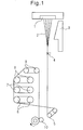
- Fig. 1 is an example of the equipment for producing the polyamide fiber of the present invention and depicts a two-stage stretching process.
- a filament yarn 2 spun out from a spinneret pack 1 provided in a melt spinning machine is immediately cooled/solidified with cold air at 0.5 to 1.2 m/sec fed from a cold air tube 3.
- a spin finish oil is applied at 0.5 to 2.0% through an oiling nozzle 4, and the fiber is taken off by winding it around a take-off roll 5.
- the spin finish roll applied may be aqueous or non-aqueous but is preferably a non-hydrous spin finish oil.
- examples of the spin finish oil include a non-aqueous spin finish oil obtained by diluting an alkyl ether ester as a lubricant component, an alkylene oxide adduct of a higher alcohol as a surfactant component, an organic phosphate salt as an extreme-pressure agent component, and the like with a mineral oil.
- the taken-off unstretched yarn is continuously delivered to a stretching step without being once taken up.
- the stretching process is performed by a multistage stretching method.
- Each of the former stretching and latter stretching is performed by a multistage stretching method.
- the filament yarn is preferably stretched by utilizing the difference in speed between rolls.
- the number of stretching stages is not particularly limited, but preferably a two-stage stretching process, more preferably a three-stage stretching process, is used.
- a first stretching roll 6, a second stretching roll 7, a third stretching roll 8, and a relax roll 9 are provided, and stretching, heat treatment and the like are performed by sequentially winding the filament yarn over respective rolls to obtain desired physical properties.
- a light tension is kept between the take-off roll and the first stretching roll.
- the stretch percentage between the rolls is preferably from 0.5 to 5%.
- the surface temperature of the take-off roll is preferably from 20 to 50°C.
- the temperature of the first stretching roll is preferably from 40°C to less than 150°C.
- the temperature of the second stretching roll for latter stretching of performing the stretching in a high temperature region is preferably from 150 to 230°C.
- the third stretching roll and the relax roll are preferably set to a temperature of 150 to 250°C.
- the draw ratio in cold stretching at less than 150°C is set to be from 25 to 55% of the total draw ratio.
- the first-stage stretching performed between the first stretching roll and the second stretching roll may be set to a ratio of 25 to 55%, preferably from 30 to 50%, based on the total draw ratio.
- stretching may be performed until reaching a total draw ratio in a level sufficient to develop the desired strength.
- hot stretching in the second stage performed between the second stretching roll and the third stretching roll after cold stretching in the first stage may be performed at the remaining draw ratio.
- the percentage of hot stretching based on the total draw ratio becomes relatively high, and orientational crystallization due to stretching and thermal crystallization due to roll heating proceed in combination, as a result, a high-strength yarn may not be obtained or even if obtained, many broken filaments in yarn may be produced, giving rise to a problem in the quality.
- Keeping the cold stretching stage to a ratio of 55% or less leads to sufficient development of the polymer structure in the subsequent hot stretching stage and increase in the slack recovery rate A after fixed-length dry heat treatment. In turn, the loosening resistance of a fabric produced is advantageously improved.
- the initial hot stretching roll (second stretching roll 7) in the hot stretching part has a satin finish surface to increase the roughness, and thus the yarn appropriately slides on the roll.
- stretching is performed not only between former and latter rolls differing in the speed but also on the same-stage roll by utilizing the sliding until the filament yarn and roll speeds reach the same speed so as to slowly change the strain rate, whereby the ratio of hot stretching in the second stage can be increased.
- the roughness Ra of the initial hot stretching roll (second stretching roll 7) is preferably 2.0 ⁇ m or more, more preferably from 2.0 to 5.0 ⁇ m, still more preferably from 3.0 to 5.0 ⁇ m, yet still more preferably from 3.5 to 5.0 ⁇ m.
- the roughness is 2.0 ⁇ m or more, a sufficiently large speed difference between the filament yarn speed and the roll speed is produced on the roll, and slow stretching results.
- the roughness is 5.0 ⁇ m or less, the roll can be worked to produce sufficiently uniform surface roughness.
- a relaxation treatment in a total amount of more than 0% to 14.0% is preferably performed between after the stretching and before a winder so as to relax the stress and strain residing in the filament yarn. Furthermore, in the relaxation treatment, stepwise relaxation is preferably performed.
- the temperature of the third stretching roll is set higher than the temperature of the relax roll.
- relaxation and take-off by the relax roll occur owing to the temperature of the third stretching roll, and then, the filament yarn is taken up while again undergoing relaxation between the relax roll lower in the lower temperature than the third stretching roll and a winder. That is, this step is performed in two stages while lowering the heat setting temperature.
- Preferred temperatures of the third stretching roll and the relax roll which work out to the heat setting temperature, are respectively from 250 to 150°C and from 180 to 50°C.
- the temperature of the relax roll is more preferably from 160 to 70°C, still more preferably from 150 to 80°C.
- the heat treatment is preferably performed by stepwise lowering the temperature.
- the first relaxation treatment that is, relaxation between the third stretching roll and the relax roll, is preferably performed in excess of 2.0% so as to increase the slack recovery rate A.
- the relaxation treatment involves relaxation in excess of 0.5% between the relax roll and the winder, and taking-up in the relaxation condition makes it easy to maintain the mechanical properties after a heat resistance test. If taking-up is performed in the tension condition by completing a relaxation treatment at 50°C or more before taking-up, mechanical properties can be hardly maintained after a heat resistance test.
- the filament yarn subjected to the relaxation treatment is taken up by a winder 10.
- the filament yarn may be taken up while bundling the filament yarns by blowing a high-pressure fluid onto the filament yarn between the relax roll and the winder to interlace the filament yarns.
- a known interlacing apparatus may be used without any problem.
- the total draw ratio from the take-off roll to the final stretching roll i.e., in the case of the above-described two-stage stretching process, the third roll, may vary depending on the characteristics of the polymer or the spinning and cooling conditions of the spun yarn but is set to a draw ratio capable of developing the required tensile strength and is preferably from 4.0 to 6.0 times.
- a plain fabric As for the woven structure of the airbag fabric of the present invention, a plain fabric, a twill fabric, a satin fabric, a deformation thereof, and the like can be used, but the present invention is not limited thereto.
- a plain fabric In view of fabric cost and isotropic deployment of the airbag, a plain fabric is preferably used.
- the fabric may not necessarily have a symmetric structure but may have an asymmetric structure.
- the asymmetric structure as used herein means the relationship between warp yarn and weft yarn, for example, means the difference in the yarn density or structure, that is, the structure differs in the plain fabric, for example, the number of yarns differs between the warp yarn and the weft yarn, one member of warp and weft uses a different yarn species, or one member of warp and weft has a ripstop or shadow stripe structure.
- a double-ply fabric may be woven by a Jacquard loom and formed into an airbag by hollow weaving.
- the weaving machine is not particularly limited, and a waterjet loom, an airjet loom, a rapier loom, and the like can be used.
- Scouring after weaving can be performed by a known method.
- hot-water washing or warm water washing with a detergent may be performed by using a jigger scouring machine or the like in the case of a batch process, and using an open soaper or the like in the case of a continuous process.
- the water temperature is from 60 to 120°C, and pressure scouring can also be performed.
- the fabric can be passed through a hot bath a plurality of times by repeating the turnaround, and the temperature may be sequentially changed by replacing the hot bath, or the detergent component may be changed.
- the fabric can be dipped a plurality of time by employing a multistage immersion bath, and in the multistage bath, the temperature may be changed sequentially, or the detergent component may be changed.
- scouring after weaving may also be omitted.
- the yarn-making oil may fall off substantially, making it possible to omit scouring after weaving, and this is economically preferred.
- the fabric After waterjet weaving, scouring and the like, the fabric can be dried.
- a hot air dryer, a hot roller heater, and the like are used.
- the temperature can be set in the range of 100 to 200°C.
- Heat setting may be performed at the same time by using a device capable of controlling the tension in the warp direction, that is, the fabric running direction, or in the weft direction, that is, the fabric width direction.
- a hot roller heater, a tenter and the like can be used.
- the tension during heating is preferably controlled using a tenter.
- the fabric can be used as a non-coated airbag base fabric by weaving it at a high density.
- the fabric when the fabric is coated and made air-impermeable by the film formed, the fabric can be used as a coated airbag base fabric.
- the coating method all of the methods such as knife coating, comma coating, roll coating, dip coating and spray coating can be performed.
- air knife coating is preferred to obtain a flexible coated base fabric by forming a relatively thin film on the fabric surface and allowing little penetration of the coating material.
- various elastomers can be used as the coating material. Silicone is preferred because of its excellent cold flexibility as well as durability, and a solventless addition-type silicone is more preferred.
- the addition-type silicone undergoes a crosslinking reaction at 150 to 200°C and therefore, passes through a heating and vulcanizing step.
- a heating process to control the fabric configuration on heating the fabric and the difference in crimp percentage between warp and weft is also preferred.
- the airbag fabric of the present invention is cut and sewn and thereby can provide an airbag. Also, when the airbag fabric is woven by hollow weaving, an airbag is formed by cutting outside the portion where a bag is formed by a binding structure.
- the obtained airbag is used as an airbag device after attaching an inflator to the gas inlet of the airbag.
- the inflator a pyro type, a hybrid type, a stored gas type, and the like are used.
- the airbag includes a driver's seat airbag, a passenger seat airbag, a side airbag, a side curtain airbag, a rear wind shield airbag, a pedestrian protection airbag, and the like.
- the roughness is a value measured using a surface roughness meter (Surfcorder SE-40D, manufactured by Kosaka Laboratory Ltd.) in accordance with the standard for stylus surface roughness measurement of JIS B0651, and the centerline average roughness (Ra) was measured.
- the single yarn fineness was determined by dividing the total fineness determined by the method described in JIS L 1017 8.3, by the number of single yarn filaments constituting the filament yarn.
- the tensile strength was determined by dividing the tensile strength measured by the method described in JIS L 1017 8.5, by the total fineness. Also, the elongation at break was determined.
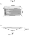
- a filament yarn was wound around a frame of 400 mm in width (15 turns at a winding tension of 0.2 cN), fixed by tying the end of yarn to the frame, heat-treated for 24 hours in an environment of 120°C by using a hot air dryer, and then left to stand still in the normal state, and the slack was measured by continually applying, as shown in Fig. 2(b) , a load over time. The load was applied to 5 filament yarns by using a weight to become 0.01 cN/dtex.
- the measurement over time after heat treatment was performed by measuring the slack immediately (within 1 hr) and after 6 hr, 24 hr, 48 hr and 72 hr, and the point at which the displacement from the previous measurement became 0.1 mm or less was regarded as stabilized.
- the percentage change between the amount of slack when measured within 1 hour after heat treatment and the amount of slack when stabilized was taken as the slack recovery rate (A).
- A Ta ⁇ Tb / Ta ⁇ 100
- Ta is the amount of slack immediately after heat treatment
- Tb is the amount of slack when stabilized after heat treatment.
- the shrinkage in boiling water was measured by the method described in JIS L 1017 8.14.
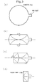
- the fabric was cut into a circular shape large enough to ensure a diameter of 30 cm, and a simulated airbag was sewn in the manner of laminating together two sheets of the circularly cut fabric.
- a gas inlet of 100 mm ⁇ 80 mm was provided in the airbag, and the laminated portion of the inlet in the airbag was partially inserted into a tubular gas injection port and hermetically fixed to allow for no gas leakage. Subsequently, as shown in Figs.
- the simulated airbag expanding in a semicircle to the right and left with respect to the gas inlet was folded toward the center by avoiding overlap between respective folds and thereafter, folded three times at intervals of 10 cm from the side opposite the gas inlet toward the inlet side.
- the point at which when a compressed helium gas of 7.5 MPa in a 720-cc tank was introduced at a burst into the airbag, the airbag inner pressure became maximum was regarded as the deployment completion point, and the deployability was relatively evaluated by the completion point arrival time.
- the deployability was evaluated as follows by the deployment completion time. The test was performed 3 times, and the average value thereof was used as the deployment completion time.
- the airbag was examined for the overall appearance and evaluated according to the following criteria.
- Spinning was performed using the equipment shown in Fig. 1 .
- a pellet-like nylon 66 polymer having a formic acid relative viscosity of 100 and containing 50 ppm of copper element and 1,600 ppm of iodine was melted at a temperature of 295°C by using an extruder-type extruding machine, then homogenized in the temperature to 300°C by a spin head, weighed in a gear pump from the spin head to give the fineness shown in Table 1, and spun out from the spinneret pack.
- the spun-out polymer was cooled/solidified with cold air to form a filament yarn.
- the solidified filament yarn was provided with a spin finish oil and without being once taken up, taken off by the take-off roll.
- the taken-off filament yarn was stretched by 1% between the take-off roll and the first stretching roll and then subjected to first-stage stretching of 2.25 times between the first stretching roll and the second stretching roll and further to second-stage stretching of 2.35 times between the second stretching roll and the third stretching roll.
- the filament yarn after stretching was relaxed by 3.5% between the third stretching roll and the relax roll and thereafter, while appropriately interlacing the yarns by an interlacing apparatus (not shown), taken up with relaxation of 3.5%, i.e., at a speed ratio of 0.965, between the relax roll and the winder.
- the temperatures of the take-off roll, the first stretching roll, the second stretching roll, the third stretching roll and the relax roll were respectively non-heated, 60°C, 200°C, 170°C and 150°C, and the number of windings of the filament yarn on the rolls was set to 1, 2, 3, 2 and 1, respectively. At this time, the total draw ratio was 5.34 times.
- the roughness Ra of the hot stretching roll (second stretching roll) was set to 4.0 ⁇ m.
- the obtained nylon 66 original yarn was warped at a speed of 500 m/min and then woven at a rotation speed of 800 rpm by using a waterjet loom (ZW303) manufactured by Tsudakoma Corp. to obtain a fabric.
- the weave density of warp and weft yarns was adjusted to 74 ends ⁇ 74 ends per 2.54 cm through cylinder drying at 120°C, and in this way, a base fabric for airbag fabric was obtained.
- This base fabric was cut, sewn and used for a deployability test and a loosening resistance and burst resistance test. The results obtained are shown in Table 1 together with the evaluation results of the filament yarn.
- Example 1 Melt spinning was performed in the same manner as in Example 1 to give the fineness shown in Table 1 by using the same nylon 66 polymer as in Example 1.
- the taken-off filament yarn was stretched by 1% between the take-off roll and the first stretching roll and then subjected to first-stage stretching of 1.90 times between the first stretching roll and the second stretching roll and further to second-stage stretching of 2.80 times between the second stretching roll and the third stretching roll.
- the filament yarn after stretching was relaxed by 5.5% between the third stretching roll and the relax roll and thereafter, taken up by the winder while appropriately interlacing the yarns by an interlacing apparatus. Between the relax roll and the winder, the filament yarn was taken up with relaxation of 4.0%.
- the temperatures of the take-off roll, the first stretching roll, the second stretching roll, the third stretching roll and the relax roll were respectively non-heated, 60°C, 200°C, 200°C and 150°C, and the number of windings of the filament yarn on the rolls and the roughness of the hot stretching roll (second stretching roll) were set in the same manner as in Example 1.
- An airbag fabric was obtained in the same manner as in Example 1 except that the obtained nylon 66 original yarn was used and the weave density of warp and weft yarns was adjusted to 55 ends ⁇ 55 ends, and used for a deployability test and a loosening resistance and burst resistance test. The results obtained are shown in Table 1 together with the evaluation results of the filament yarn.
- Example 2 Melt spinning was performed in the same manner as in Example 2 to give the fineness shown in Table 1 by using the same nylon 66 polymer as in Example 1.
- the filament yarn taken off by the take-off roll was subjected to the same stretching and relaxation treatments as in Example 2 except that the draw ratio between the first stretching roll and the second stretching roll was set to 2.00 times, the draw ratio between the second stretching roll and the third stretching roll was set to 2.45 times, and the relaxation between the third stretching roll and the relax roll was set to 4.5%.
- An airbag fabric was obtained in the same manner as in Example 1 except that the obtained nylon 66 original yarn was used and the weave density of warp and weft yarns was adjusted to 55 ends ⁇ 55 ends, and evaluated in the same manner as in Example 1. The results obtained are shown in Table 1 together with the evaluation results of the filament yarn.
- a nylon 66 original yarn obtained in the same manner as in Example 3 was wound around a frame, fixed by tying the end of yarn to the frame, and subjected to heat aging of 110°C ⁇ 3000 hr in a hot air dryer.
- the nylon 66 original yarn was measured for the tensile strength and tensile elongation at break before and after aging, and the physical property retention percentage was calculated. The measurement was performed 10 times, and the measured values were averaged. The results obtained are shown in Table 1.
- Example 2 Melt spinning was performed in the same manner as in Example 2 to give the fineness shown in Table 1 by using the same nylon 66 polymer as in Example 1.
- the filament yarn taken off by the take-off roll was subjected to the same stretching and relaxation treatments as in Example 2 except that the draw ratio between the first stretching roll and the second stretching roll was set to 1.65 times, the draw ratio between the second stretching roll and the third stretching roll was set to 3.00 times, the relaxation between the third stretching roll and the relax roll was set to 4.0%, the relaxation between the relax roll and the winder was set to 2.0%, and the temperature of the third stretching roll was set to 170°C.
- Example 1 An airbag fabric was obtained in the same manner as in Example 1 except that the obtained nylon 66 original yarn was used and the weave density of warp and weft yarns was adjusted to 55 ends ⁇ 55 ends, and evaluated in the same manner as in Example 1. The results obtained are shown in Table 1 together with the evaluation results of the filament yarn.
- a nylon 66 original yarn obtained in the same manner as in Example 5 was wound around a frame, fixed by tying the end of yarn to the frame, and subjected to heat aging of 110°C ⁇ 3000 hr in a hot air dryer.
- the nylon 66 original yarn was measured for the tensile strength and tensile elongation at break before and after aging, and the physical property retention percentage was calculated. The measurement was performed 10 times, and the measured values were averaged. The results obtained are shown in Table 1.
- Example 1 Melt spinning was performed in the same manner as in Example 1 to give the fineness shown in Table 1 by using the same nylon 66 polymer as in Example 1.
- the filament yarn taken off by the take-off roll was subjected to the same stretching and relaxation treatments as in Example 1 except that the draw ratio between the first stretching roll and the second stretching roll was set to 3.45 times, the draw ratio between the second stretching roll and the third stretching roll was set to 1.50 times, the roughness Ra of the hot stretching roll (second stretching roll) was set to 1.5 ⁇ m, the relaxation between the relax roll and the winder was set to 3.0%, the temperature of the second stretching roll was set to 210°C, the temperature of the third stretching roll was set to 180°C, and the number of windings of the filament yarn on the third stretching roll was set to 3.
- the draw ratio between the first stretching roll and the second stretching roll was set to 3.45 times
- the draw ratio between the second stretching roll and the third stretching roll was set to 1.50 times
- the roughness Ra of the hot stretching roll (second stretching roll) was set
- Example 1 An airbag fabric was obtained in the same manner as in Example 1 except for using the obtained nylon 66 original yarn and evaluated in the same manner as in Example 1. The results obtained are shown in Table 1 together with the evaluation results of the filament yarn. With respect to the deployability, a good result was obtained, but when the outer appearance of the airbag was examined, weave loosening was observed.
- a pellet-like nylon 66 polymer having a formic acid relative viscosity of 110 and containing 50 ppm of copper element and 1,600 ppm of iodine was melted at a temperature of 295°C by using an extruder-type extruding machine, then homogenized in the temperature to 300°C by a spin head, weighed in a gear pump from the spin head to give the fineness shown in Table 1, and spun out from the spinneret pack.
- the spun-out polymer was cooled/solidified with cold air to form a filament yarn.
- the solidified filament yarn was provided with a spin finish oil and without being once taken up, taken off by the take-off roll.
- the taken-off filament yarn was stretched by 1% between the take-off roll and the first stretching roll and then subjected to first-stage stretching of 3.72 times between the first stretching roll and the second stretching roll and further to second-stage stretching of 1.30 times between the second stretching roll and the third stretching roll.
- the filament yarn after stretching was relaxed by 6.0% between the third stretching roll and the relax roll and thereafter, while appropriately interlacing the yarns by an interlacing apparatus, taken up with relaxation of 4.0% between the relax roll and the winder.
- the temperatures of the take-off roll, the first stretching roll, the second stretching roll, the third stretching roll and the relax roll were respectively non-heated, 60°C, 210°C, 230°C and 170°C, and the number of windings of the filament yarn on the rolls was set to 1, 2, 3, 4 and 1, respectively. At this time, the total draw ratio was 4.88 times.
- the roughness Ra of the hot stretching roll (second stretching roll) was set to the same roughness as in Comparative Example 1.
- the obtained nylon 66 original yarn was warped at a speed of 500 m/min and then woven at a rotation speed of 800 rpm by using a waterjet loom (ZW303) manufactured by Tsudakoma Corp. to obtain a fabric.
- the weave density of warp and weft yarns was adjusted to 55 ends ⁇ 55 ends through cylinder drying at 120°C, and in this way, a base fabric for airbag fabric was obtained.
- An airbag was sewn from this base fabric and used for a deployability test and a loosening resistance and burst resistance test. The results obtained are shown in Table 1 together with the evaluation results of the filament yarn.
- the deployability was relatively good, but when the outer appearance of the airbag was examined, weave loosening was observed.
- Example 2 Melt spinning was performed in the same manner as in Comparative Example 2 to give the fineness shown in Table 1 by using the same pellet-like nylon 66 polymer as in Example 1.
- the taken-off filament yarn was stretched by 1% between the take-off roll and the first stretching roll and then subjected to first-stage stretching of 3.40 times between the first stretching roll and the second stretching roll and further to second-stage stretching of 1.4 times between the second stretching roll and the third stretching roll.
- the filament yarn after stretching was relaxed by 8.0% between the third stretching roll and the relax roll and thereafter, while appropriately interlacing the yarns by an interlacing apparatus, taken up by the winder with relaxation of 1.5% between the relax roll and the winder.
- the temperatures of the take-off roll, the first stretching roll, the second stretching roll, the third stretching roll and the relax roll were respectively non-heated, 60°C, 210°C, 150°C and 150°C, and the number of windings of the filament yarn on the rolls was set to 1, 2, 3, 2 and 1, respectively.
- the roughness of the hot stretching roll (second stretching roll) was set to the same roughness as in Comparative Example 1.
- a base fabric for airbag fabric was obtained in the same manner as in Comparative Example 2 by using the obtained nylon 66 original yarn, and an airbag was sewn and used for a deployability test and a loosening resistance and burst resistance test. The results obtained are shown in Table 1 together with the evaluation results of the filament yarn. The deployment speed was slow, and a bag burst was confirmed.
- Example 1 Melt spinning was performed to give the fineness shown in Table 1 by using the same nylon 66 polymer as in Example 1.
- the filament yarn taken off by the take-off roll was stretched by 1% between the take-off roll and the first stretching roll and then subjected to first-stage stretching of 3.27 times between the first stretching roll and the second stretching roll and further to second-stage stretching of 1.56 times between the second stretching roll and the third stretching roll.
- the filament yarn after stretching was relaxed by 4.5% between the third stretching roll and the relax roll and thereafter, while appropriately interlacing the yarns by an interlacing apparatus, taken up by the winder with relaxation of 3.0% between the relax roll and the winder.
- the temperatures of the take-off roll, the first stretching roll, the second stretching roll, the third stretching roll and the relax roll were respectively non-heated, 60°C, 210°C, 200°C and 150°C, and the number of windings of the filament yarn on the rolls was set to 1, 2, 3, 2 and 1, respectively.
- the roughness of the hot stretching roll (second stretching roll) was set to the same roughness as in Comparative Example 1.
- a base fabric for airbag fabric was obtained in the same manner as in Comparative Example 2 by using the obtained nylon 66 original yarn, and an airbag was sewn and used for a deployability test and a loosening resistance and burst resistance test. The results obtained are shown in Table 1 together with the evaluation results of the filament yarn.
- the deployability was relatively good, but when the outer appearance of the airbag was examined, weave loosening was observed.
- Example 2 Melt spinning was performed in the same manner as in Example 1 to give the fineness shown in Table 1 by using the same nylon 66 polymer as in Example 1. However, in this Example, the relax roll was not used.
- the filament yarn taken off by the take-off roll was stretched by 1% between the take-off roll and the first stretching roll and then subjected to first-stage stretching of 2.0 times between the first stretching roll and the second stretching roll and further to second-stage stretching of 2.7 times between the second stretching roll and the third stretching roll.
- the number of windings of the filament yarn on the take-off roll, the first stretching roll, the second stretching roll and the third stretching roll was set to 1, 2, 3 and 4, respectively, and while appropriately interlacing the yarns by an interlacing apparatus, the filament yarn was relaxed by 5.0% between the third roll and the winder and then taken up by the winder.
- the temperatures of the take-off roll, the first stretching roll, the second stretching roll and the third stretching roll were respectively non-heated, 70°C, 225°C and 190°C, and the roughness Ra of the second stretching roll was set to 4.0 ⁇ m.
- An airbag fabric was obtained in the same manner as in Example 1 except for using the obtained nylon 66 original yarn and setting the weave density of warp and weft yarns to 55 ends ⁇ 55 ends per 2.54 cm and used for a deployability test and a loosening resistance and burst resistance test.
- the results obtained are shown in Table 1 together with the evaluation results of the filament yarn. The deployment speed was slow, and when the outer appearance of the airbag was examined, weave loosening was observed.
- the polyamide fiber of the present invention and a fabric thereof can be suitably utilized in the industrial material field, particularly, as an original fiber or fabric for an airbag.
Description
- The present invention relates to a polyamide fiber suitable for an airbag fabric. More specifically, the present invention relates to a polyamide fiber suitable for an airbag fabric capable of performing high-speed deployment and excellent in burst resistance.
- A polyamide fiber is excellent in toughness, adhesiveness, fatigue resistance and the like, and therefore is being widely used, for example, in a tire cord, a rubber-reinforcing cord for conveyer belt, power transmission belt, rubber hose and the like, a safety belt, a tent, a braid, a sewing thread and an airbag. Reducing the amount of a material such as fiber without impairing the function is required of these industrial materials and products.
- Among others, a light-weight airbag mounted in a vehicle is necessary from the standpoint of improving fuel efficiency of a vehicle or compact cabin space. On the other hand, burst resistance sufficient to cause no rupture during high-speed and high-pressure deployment is also demanded to ensure safety in a car accident.
- In recent years, a curtain airbag, side airbag, knee airbag, rear airbag and the like are being put into practice, in addition to a driver's seat airbag and a passenger seat airbag, and the required properties vary according to the storage portion or capacity. For example, in the case of a driver's seat airbag, an airbag fabric foldable into a compact configuration is demanded so as to ensure visibility in front of the vehicle or facilitate viewing of gauges. The curtain airbag needs to cover the entire side surface of a vehicle, and therefore has a large feature or a complicated shape and in addition, considering the sideway rolling of the vehicle after a side collision, the deployed bag is required to maintain an inflated state for a certain amount of time. Also, in the case of a side airbag, a knee airbag and the like, since the storage site and the passenger are close to each other and the bag actuation distance is restricted, the airbag must be deployed in a shorter time. Accordingly, it is more strongly demanded to enable high-speed deployment and enhance/maintaining burst resistance while realizing weight reduction and compactness.
-
Patent Documents -
Patent Document 3 discloses a technique for obtaining a side airbag fabric having excellent performance in terms of storability, low impact and high-speed deployment. However, the fiber used in this technique has absolutely low fineness and, despite excellent performance in terms of storability, low impact and high-speed deployment, the mechanical strength is lacking. In addition, because of a polyester, the heat capacity is small as compared to a polyamide, causing a problem in airbag deployment where a deployment gas reaches a high temperature. -
Patent document 4 discloses a 235-470 dtex multifilament polyamide yarn having a tensile strength of 9.2-10.3 cN/dtex and a boiling water shrinkage of 4.2-10.1%. The yarn is used in a woven fabric to make an airbag having a.o. an improved deployability. Further disclosed therein is a method for producing such yarn wherein a yarn spun from a spinneret is subjected to a multistage stretching treatment consisting of a cold stretching stage and a hot stretching stage and is then taken up, wherein stretching for 38-39% of the total draw ratio is performed in the cold stretching stage at 60°C and the remaining stretching is performed in the hot stretching stage at 160°C, 210°C or 220°C. The yarn is then relaxed is a single stage relaxation step with 3-5% total relaxation ratio at a temperature of 150-180 °C. - Patent document 5 discloses a 220-540 dtex polyamide multifilament yarn to be woven into an airbag fabric, the yarn having a tensile strength of 8.42-8.68 cN/ dtex and a boiling water shrinkage of 7.5-10%. The yarn is produced by a method comprising a multistage stretch consisting of a cold stretch (78% of total draw ratio) at a temperature below 150°C and a hot stretch at 200°C. The yarn is then 4% relaxed at 150°C and further 3% relaxed at 150°C between the final roller and the winder.
-
- Patent Document 1: Japanese Unexamined Patent Publication No.
6-248508 - Patent Document 2: Japanese Unexamined Patent Publication No.
6-299411 - Patent Document 3: Japanese Unexamined Patent Publication No.
8-011660 - Patent Document 4:
JP 2011 168919 A - Patent Document 5:
JP 2006 183205 A - An object of the present invention is to provide a polyamide fiber for obtaining a fabric excellent in the mechanical properties and loosening resistance after weaving, and an airbag fabricated using a fabric composed of the fiber, which is compact, excellent in storability and loosening resistance, deployable at a high speed and excellently resistant to bursting.
- As a result of intensive studies to attain the above-described object, the present inventors have found that the thermal behavior of weaving yarn in the heat treatment when weaving an airbag fabric is related to the loosening resistance. The present invention has been accomplished based on this finding. That is, the present invention provides the following aspects.
- (1) A polyamide fiber, wherein the total fineness is from 100 to 700 dtex, the tensile strength is from 8.0 to 11.5 cN/dtex, the shrinkage in boiling water is from 4.0 to 11.0%, the slack recovery rate A after fixed-length dry heat treatment represented by the following formula (1) is from 0 to 4.0%, and the tightening factor F represented by the following formula (2) is 3.8 or more:


wherein said polyamide fiber is obtained by a method in which a yarn spun from a spinneret is subjected to a multistage stretching treatment consisting of a cold stretching stage and a hot stretching stage and then taken up, stretching for 25 to 55% of the total draw ratio is performed in the cold stretching stage at less than 150°C and the remaining stretching is performed in the hot stretching stage at 150°C or more,
wherein after the multistage stretching treatment, a stepwise heat set and relaxation treatment involving a stepwise drop of temperature between 250°C and 50°C is applied in two or more stages and the yarn is then taken up and wherein the relaxation treatment in the stepwise heat set and relaxation treatment involves relaxation in excess of 0.5% between the last roll and the winder. - (2) The polyamide fiber according to (1) above, wherein the physical property retention percentage of tensile strength and tensile elongation at break after a heat resistance test at 110°C for 3,000 hours is 80% or more.
- (3) The polyamide fiber according to (2) above, wherein the physical property retention percentage of tensile strength and tensile elongation at break after a heat resistance test at 110°C for 3,000 hours is 90% or more.
- (4) An airbag fabric comprising the polyamide fiber according to any one of (1) to (3) above.
- (5) An airbag comprising the airbag fabric according to (4) above.
- (6) A method for producing a polyamide fiber according to any of (1) to (3) above, wherein when a filament yarn spun from a spinneret is subjected to a multistage stretching treatment consisting of a cold stretching stage and a hot stretching stage and then taken up, stretching for 25 to 55% of the total draw ratio is performed in the cold stretching stage at less than 150°C and the remaining stretching is performed in the hot stretching stage at 150°C or more, wherein after the multistage stretching treatment, a stepwise heat set and relaxation treatment involving a stepwise drop of temperature between 250°C and 50°C is applied in two or more stages and the yarn is then taken up and wherein the relaxation treatment in the stepwise heat set and relaxation treatment involves relaxation in excess of 0.5% between the last roll and the winder.
- (8) The method for producing a polyamide fiber according to (6) or (7) above, wherein the surface of the initial roll in the hot stretching stage is a satin finish surface having a roughness Ra of 2 µm or more.
- The polyamide fiber of the present invention shows an appropriate thermal behavior in a heat treatment step after weaving, and therefore is excellent in loosening resistance. Also, the polyamide fiber of the present invention can provide a fabric for an airbag that is deployable at a high speed, excellently resistant to bursting, compact, and excellent in storability.
-
-
Fig. 1 is a view illustrating one example of the equipment for producing the polyamide fiber of the present invention. -
Fig. 2 is a view for explaining the method for measuring the slack recovery rate after fixed-length dry heat treatment. -
Fig. 3 is a plan view of a circular simulated airbag used in Examples. - The polymer constituting the polyamide fiber of the present invention includes
polyamide 6,polyamide 6·6, polyamide 11, polyamide 12,polyamide 6·10,polyamide 6·12,polyamide 4·6, a copolymer thereof, and a polymer composed of a mixture thereof. Among these, polyamide 6-6 is preferred, and thepolyamide 6·6 fiber is mainly composed of a polyhexamethylene adipamide fiber. The polyhexamethylene adipamide fiber indicates a polyamide fiber consisting of 100% of hexamethylenediamine and adipic acid and having a melting point of 250°C or more, but in thepolyamide 6·6 fiber for use in the present invention,polyamide 6,polyamide 6·I,polyamide 6·10,polyamide 6·T or the like may be copolymerized or blended with polyhexamethylene adipamide as long as the melting point is kept from becoming less than 250°C. Incidentally, such a fiber may contain various additives usually used for improving the productivity or characteristics in the production step or processing step of the original yarn. For example, a thermal stabilizer, an antioxidant, a light stabilizer, a lubricating agent, an antistatic agent, a plasticizer, a thickener, a pigment and a flame retardant may be incorporated. - The total fineness of the polyamide fiber of the present invention is from 100 to 700 dtex, more preferably from 150 to 600 dtex, still more preferably from 200 to 470 dtex, yet still more preferably from 210 to 360 dtex. As the total fineness is 100 dtex or more and is larger, the mechanical strength is more satisfactory, and as the total fineness is 700 dtex or less and is smaller, the storability is more excellent.
- The single yarn fineness is preferably from 1 to 7 dtex, more preferably from 1.5 to 6.0 dtex, still more preferably from 2.5 to 5.7 dtex, yet still more preferably from 3.3 to 4.9 dtex. With a single yarn fineness of 1 dtex or more, the yarn hardly suffers from the problem in productivity and can have suitable weavability. As the single yarn fineness is 7 dtex or less and is smaller, the fabric obtained is softer and can be folded into a more compact configuration, leading to enhanced storability, and the flatness of the fabric is improved to ensure an airbag advantageous for high-speed deployment. Even under high differential pressure as when deploying an airbag, low air permeability is readily obtained.
- The tensile strength is from 8.0 to 11.5 cN/dtex, more preferably from 8.5 to 11.5 cN/dtex, still more preferably from 9.5 to 11.5 cN/dtex, yet still more preferably from 9.8 to 11.5 cN/dtex. When the strength is 8.0 cN/dtex or more, the intended mechanical properties of the present invention are obtained and the fiber is sufficient as a fiber for industrial materials, whereas when the strength is 11.5 cN/dtex or less, the fiber quality is excellent and, for example, the occurrence frequency of broken filaments in yarn is low, as a result, reduction in the spinning yield does not occur or a weaving trouble in the post-processing is not caused.
- The intermediate elongation in the tensile test is preferably less than 12.5%, more preferably 12.0% or less, and most preferably 11.5% or less. A smaller intermediate elongation of less than 12.5% contributes to increasing the later-described slack recovery rate after fixed-length dry heat treatment. On the other hand, the intermediate elongation is preferably 8.0% or more so as to facilitate retaining the mechanical properties after a heat resistance test.
- The polyamide fiber of the present invention is woven and used preferably for application as an industrial material, in particular, an airbag fabric. As the airbag fabric, in view of mechanical properties and low air permeability, a high-density fabric increased in the weave density is often used. The high-density fabric as used herein indicates a fabric having a cover factor of 1,500 or more. The cover factor of the airbag fabric of the present invention is, in view of low air permeability, preferably from 1,500 to 2,500, more preferably from 1,550 to 2,225, still more preferably from 1,600 to 2,180, yet still more preferably from 1,700 to 2,100. When the cover factor is 1,500 or more, the tensile strength or tear strength of the fabric are satisfactory, and a fabric resistant to loosening is obtained. Also, when the cover factor is 2,500 or less, the fabric is kept from excessively increasing in the rigidity or allowing for deterioration of the foldability or storability. The cover factor is represented by [√(D1)×(N1)+√(D2)×(N2)], wherein D1 is the warp total fineness (dtex), N1 is the warp density (ends/2.54 cm), D2 is the weft total fineness (dtex), and N2 is the weft density (ends/2.54 cm).
- Also, in order to exhibit sufficient resistance to loosening during deployment of an airbag obtained from the airbag fabric, the weaving yarn must have a property of exhibiting an appropriate thermal behavior, because the behavior of weaving yarn during heat treatment after weaving affects the air permeability or loosening of the airbag. In the fabric, slack is produced along with cooling after the heat treatment. Thereafter, a behavior of partially recovering the slack is observed. This reflects the behavior of the weaving yarn. However, the weaving yarn state of the fabric resulting from the heat treatment after weaving cannot be expressed only by the shrinkage in boiling water, which is a representative value of the heat shrinkage of fiber, and the slack recovery rate after fixed-length dry heat treatment must be taken into account. The slack recovery rate (A) after fixed-length dry heat treatment indicates the percentage change in which the fiber shrinks to recover the slack from the slacked state after fixed-length dry heat treatment in a state of being wound around a frame , that is, is represented by the following formula (1):

- In formula (1), Ta is the amount of slack immediately after heat treatment, and Tb is the amount of slack when stabilized after heat treatment.
- The slack recovery rate after fixed-length dry heat treatment is preferably from 0.1 to 4.0%, more preferably from 0.3 to 3.5%. When the slack recovery rate is 4.0% or less, the percentage dimensional change after dry heat treatment of the fabric is small. Also, the fiber molecular structure after hot aging is stable, and the strength and elongation properties are less changed. When the slack recovery rate is 0.1% or more, the weaving yarn after the heat treatment is tightened, so that the weave loosening can be suppressed. A slack recovery rate of 0% means the state where the slack is not recovered and the slacked state remains as it is. The slack recovery rate can be controlled by the ratio between cold stretching and hot stretching in the stretching conditions. By keeping the stretching in the cold stretching stage to 55% or less, the molecular structure can be sufficiently developed in the hot stretching stage and in turn, the slack recovery rate can be increased. The proportion in the cold stretching stage is the cold draw ratio based on the total draw ratio. Furthermore, when the heat setting temperature is set to multiple stages from high temperature to low temperature, this greatly contributes to enlarging the slack recovery rate.
- In addition, it has been found that the tightening factor (F) represented by the following formula (2) participates in the configuration stability of weave pattern:

- In formula (2), A is the slack recovery rate after fixed-length dry heat treatment, and B is the shrinkage in boiling water.
- In the present invention, the tightening factor F is 3.8 or more, more preferably from 3.8 to 8.0, still more preferably from 3.8 to 5.5, yet still more preferably from 3.8 to 4.5. When F is 3.8 or more, the fiber recovers from the slacked state produced after post-weaving heat treatment, as a result, the weave loosening is suppressed, and air permeability through a loosening of the fabric is reduced. Also, loosening under stress during airbag deployment is suppressed, and the airbag deployment speed rises. On the other hand, when the tightening factor F is 8.0 or less, the dimensional change produced during processing after weaving is relatively stable, and a wrinkle or the like is less likely to occur. The tightening factor F is restricted also by the slack recovery rate A after fixed-length dry heat treatment and the upper limit of the shrinkage B in boiling water.
- The shrinkage in boiling water is from 4.0 to 11.0%, more preferably from 5.0 to 10.5%, still more preferably from 6.0 to 10.5%. The shrinkage in boiling water, where a weaving yarn having a stable performance such as quality in terms of broken filaments in yarn is obtained as a high-strength fiber, is substantially 11.0% or less. When the shrinkage in boiling water is 4.0% or more, a high-density fabric is easily obtained. The shrinkage in boiling water can be controlled by the heat setting temperature, the roll contact or residence time, and the amount of relaxation by a relax roll. In these relaxation treatments, not only a strain produced by hot stretching can be removed but also by adjusting the heat setting temperature or the roll contact or residence time, the structure achieved by stretching can be fixed or the orientation in the amorphous region can be relaxed to establish a proper relationship between the shrinkage in boiling water and the shrinkage after heat treatment. When the heat setting temperature is set low, the shrinkage in boiling water becomes large; when the roll contact or residence time is set short, the shrinkage in boiling water becomes large; and when the percentage of relaxation treatment is set small, the shrinkage in boiling water becomes large.
- Also, it is important to withstand the environmental load lasting for a long time after the storage of airbag and maintain a sufficient performance during deployment. In the polyamide fiber of the present invention, the physical property retention percentage of tensile strength and tensile elongation at break after a heat resistance test at 110°C for 3,000 hours is preferably 80% or more, more preferably 90% or more.
- Therefore, the polyamide fiber preferably contains a heat stabilizer. For example, the polyamide fiber preferably contains a copper element in an amount of 20 to 100 ppm and contains iodine or bromine in an amount of 500 to 3,500 ppm in terms of element. The copper element may be added in the form of a compound such as copper iodide, copper bromide and copper acetate. Also, the iodine and bromine can be added in the form of a compound such as potassium iodide and potassium bromide. In addition, the slack recovery rate A as a stabilization factor of the fiber polymer structure for preventing reduction in physical properties is 4.0% or less. The slack recovery rate A is preferably 3.5% or less.
- The polyamide fiber of the present invention can be produced by a melt spinning method.
Fig. 1 is an example of the equipment for producing the polyamide fiber of the present invention and depicts a two-stage stretching process. - A
filament yarn 2 spun out from aspinneret pack 1 provided in a melt spinning machine is immediately cooled/solidified with cold air at 0.5 to 1.2 m/sec fed from acold air tube 3. - Subsequently, a spin finish oil is applied at 0.5 to 2.0% through an oiling
nozzle 4, and the fiber is taken off by winding it around a take-off roll 5. The spin finish roll applied may be aqueous or non-aqueous but is preferably a non-hydrous spin finish oil. As for the preferred spin finish oil composition, examples of the spin finish oil include a non-aqueous spin finish oil obtained by diluting an alkyl ether ester as a lubricant component, an alkylene oxide adduct of a higher alcohol as a surfactant component, an organic phosphate salt as an extreme-pressure agent component, and the like with a mineral oil. The taken-off unstretched yarn is continuously delivered to a stretching step without being once taken up. - The stretching process is performed by a multistage stretching method. In stretching the spun yarn, it is preferred to first perform former stretching at a low temperature of less than 150°C, subsequently perform latter stretching at a high temperature of 150°C or more, based on the total draw ratio for obtaining the necessary tensile strength, and through heat setting for fixing the structure and tension relaxation by a relaxation treatment, finally take up the yarn. Each of the former stretching and latter stretching is performed by a multistage stretching method. The filament yarn is preferably stretched by utilizing the difference in speed between rolls. The number of stretching stages is not particularly limited, but preferably a two-stage stretching process, more preferably a three-stage stretching process, is used. In the stretching step depicted, a
first stretching roll 6, a second stretching roll 7, athird stretching roll 8, and arelax roll 9 are provided, and stretching, heat treatment and the like are performed by sequentially winding the filament yarn over respective rolls to obtain desired physical properties. First, a light tension is kept between the take-off roll and the first stretching roll. The stretch percentage between the rolls is preferably from 0.5 to 5%. The surface temperature of the take-off roll is preferably from 20 to 50°C. In the subsequent former stretching process, since stretching is performed in a low temperature region of less than 150°C, the temperature of the first stretching roll is preferably from 40°C to less than 150°C. The temperature of the second stretching roll for latter stretching of performing the stretching in a high temperature region is preferably from 150 to 230°C. In the subsequent heat setting, the third stretching roll and the relax roll are preferably set to a temperature of 150 to 250°C. - In the present invention, the draw ratio in cold stretching at less than 150°C is set to be from 25 to 55% of the total draw ratio. In the example depicted in
Fig. 1 , the first-stage stretching performed between the first stretching roll and the second stretching roll may be set to a ratio of 25 to 55%, preferably from 30 to 50%, based on the total draw ratio. In the subsequent hot stretching at 150°C or more, stretching may be performed until reaching a total draw ratio in a level sufficient to develop the desired strength. For example, hot stretching in the second stage performed between the second stretching roll and the third stretching roll after cold stretching in the first stage may be performed at the remaining draw ratio. If the cold stretch performed at less than 25% of the total draw ratio, the percentage of hot stretching based on the total draw ratio becomes relatively high, and orientational crystallization due to stretching and thermal crystallization due to roll heating proceed in combination, as a result, a high-strength yarn may not be obtained or even if obtained, many broken filaments in yarn may be produced, giving rise to a problem in the quality. Keeping the cold stretching stage to a ratio of 55% or less leads to sufficient development of the polymer structure in the subsequent hot stretching stage and increase in the slack recovery rate A after fixed-length dry heat treatment. In turn, the loosening resistance of a fabric produced is advantageously improved. In conventional stretching, breakage at hot stretching in the hot stretching part of the second stage is prevented by setting the cold stretching in the first stage to a ratio of more than 55%. However, in the present invention, the initial hot stretching roll (second stretching roll 7) in the hot stretching part has a satin finish surface to increase the roughness, and thus the yarn appropriately slides on the roll. As a result, stretching is performed not only between former and latter rolls differing in the speed but also on the same-stage roll by utilizing the sliding until the filament yarn and roll speeds reach the same speed so as to slowly change the strain rate, whereby the ratio of hot stretching in the second stage can be increased. The roughness Ra of the initial hot stretching roll (second stretching roll 7) is preferably 2.0 µm or more, more preferably from 2.0 to 5.0 µm, still more preferably from 3.0 to 5.0 µm, yet still more preferably from 3.5 to 5.0 µm. When the roughness is 2.0 µm or more, a sufficiently large speed difference between the filament yarn speed and the roll speed is produced on the roll, and slow stretching results. On the other hand, when the roughness is 5.0 µm or less, the roll can be worked to produce sufficiently uniform surface roughness. - In the relaxation treatment and heat setting subsequent to the stretching, a strain produced by hot stretching is removed. That is, the orientation in amorphous region is relaxed, and the structure achieved by stretching is fixed. As a result, the shrinkage in boiling water and the slack recovery rate are adjusted. When the heat setting temperature is set low, the shrinkage in boiling water tends to become large, and also, when the temperature is lowered in multiple stages by adjusting the temperatures of the third stretching roll and the relax roll, the slack recovery rate tends to rise.
- In the step of relaxation treatment and heat setting, a relaxation treatment in a total amount of more than 0% to 14.0% is preferably performed between after the stretching and before a winder so as to relax the stress and strain residing in the filament yarn. Furthermore, in the relaxation treatment, stepwise relaxation is preferably performed.
- For example, in the relaxation treatment and heat setting, the temperature of the third stretching roll is set higher than the temperature of the relax roll. First, relaxation and take-off by the relax roll occur owing to the temperature of the third stretching roll, and then, the filament yarn is taken up while again undergoing relaxation between the relax roll lower in the lower temperature than the third stretching roll and a winder. That is, this step is performed in two stages while lowering the heat setting temperature. Preferred temperatures of the third stretching roll and the relax roll, which work out to the heat setting temperature, are respectively from 250 to 150°C and from 180 to 50°C. The temperature of the relax roll is more preferably from 160 to 70°C, still more preferably from 150 to 80°C. In the heat setting and relaxation treatment, the heat treatment is preferably performed by stepwise lowering the temperature.
- In addition, out of stepwise relaxation treatment, among others, the first relaxation treatment, that is, relaxation between the third stretching roll and the relax roll, is preferably performed in excess of 2.0% so as to increase the slack recovery rate A.
- Also, the relaxation treatment involves relaxation in excess of 0.5% between the relax roll and the winder, and taking-up in the relaxation condition makes it easy to maintain the mechanical properties after a heat resistance test. If taking-up is performed in the tension condition by completing a relaxation treatment at 50°C or more before taking-up, mechanical properties can be hardly maintained after a heat resistance test.
- The filament yarn subjected to the relaxation treatment is taken up by a
winder 10. In order to prevent unraveling of the filament yarn in the weaving step, the filament yarn may be taken up while bundling the filament yarns by blowing a high-pressure fluid onto the filament yarn between the relax roll and the winder to interlace the filament yarns. As the apparatus for interlacing the filament yarns, a known interlacing apparatus may be used without any problem. - The total draw ratio from the take-off roll to the final stretching roll, i.e., in the case of the above-described two-stage stretching process, the third roll, may vary depending on the characteristics of the polymer or the spinning and cooling conditions of the spun yarn but is set to a draw ratio capable of developing the required tensile strength and is preferably from 4.0 to 6.0 times.
- As for the woven structure of the airbag fabric of the present invention, a plain fabric, a twill fabric, a satin fabric, a deformation thereof, and the like can be used, but the present invention is not limited thereto. Among these woven structures, in view of fabric cost and isotropic deployment of the airbag, a plain fabric is preferably used. The fabric may not necessarily have a symmetric structure but may have an asymmetric structure. The asymmetric structure as used herein means the relationship between warp yarn and weft yarn, for example, means the difference in the yarn density or structure, that is, the structure differs in the plain fabric, for example, the number of yarns differs between the warp yarn and the weft yarn, one member of warp and weft uses a different yarn species, or one member of warp and weft has a ripstop or shadow stripe structure. Also, a double-ply fabric may be woven by a Jacquard loom and formed into an airbag by hollow weaving. The weaving machine is not particularly limited, and a waterjet loom, an airjet loom, a rapier loom, and the like can be used.
- Scouring after weaving can be performed by a known method. For example, hot-water washing or warm water washing with a detergent may be performed by using a jigger scouring machine or the like in the case of a batch process, and using an open soaper or the like in the case of a continuous process. The water temperature is from 60 to 120°C, and pressure scouring can also be performed. In the batch process, the fabric can be passed through a hot bath a plurality of times by repeating the turnaround, and the temperature may be sequentially changed by replacing the hot bath, or the detergent component may be changed. Also in the continuous process, the fabric can be dipped a plurality of time by employing a multistage immersion bath, and in the multistage bath, the temperature may be changed sequentially, or the detergent component may be changed. Furthermore, scouring after weaving may also be omitted. In particular, when the weaving is performed by a waterjet loom, the yarn-making oil may fall off substantially, making it possible to omit scouring after weaving, and this is economically preferred.
- After waterjet weaving, scouring and the like, the fabric can be dried. As for the drying method, a hot air dryer, a hot roller heater, and the like are used. The temperature can be set in the range of 100 to 200°C. Heat setting may be performed at the same time by using a device capable of controlling the tension in the warp direction, that is, the fabric running direction, or in the weft direction, that is, the fabric width direction. As for the heat setting device, a hot roller heater, a tenter and the like can be used. Above all, when the resistance to heat shrinkage stress in the warp and weft directions of the fabric is controlled, the fabric configuration on heating the fabric and the difference in crimp percentage between warp and weft can be advantageously controlled. In both the warp and weft directions, the tension during heating is preferably controlled using a tenter.
- The fabric can be used as a non-coated airbag base fabric by weaving it at a high density. On the other hand, when the fabric is coated and made air-impermeable by the film formed, the fabric can be used as a coated airbag base fabric. As for the coating method, all of the methods such as knife coating, comma coating, roll coating, dip coating and spray coating can be performed. Among others, air knife coating is preferred to obtain a flexible coated base fabric by forming a relatively thin film on the fabric surface and allowing little penetration of the coating material. As the coating material, various elastomers can be used. Silicone is preferred because of its excellent cold flexibility as well as durability, and a solventless addition-type silicone is more preferred. The addition-type silicone undergoes a crosslinking reaction at 150 to 200°C and therefore, passes through a heating and vulcanizing step. In this step, applying a heating process to control the fabric configuration on heating the fabric and the difference in crimp percentage between warp and weft is also preferred.
- The airbag fabric of the present invention is cut and sewn and thereby can provide an airbag. Also, when the airbag fabric is woven by hollow weaving, an airbag is formed by cutting outside the portion where a bag is formed by a binding structure. The obtained airbag is used as an airbag device after attaching an inflator to the gas inlet of the airbag. As for the inflator, a pyro type, a hybrid type, a stored gas type, and the like are used. The airbag includes a driver's seat airbag, a passenger seat airbag, a side airbag, a side curtain airbag, a rear wind shield airbag, a pedestrian protection airbag, and the like.
- The present invention is described below by referring to Examples, but the present invention is not limited only to these Examples. Incidentally, the definitions and measuring methods of physical properties referred to in the description of the present invention and Examples are as follows.
- After sufficiently dissolving 4.5 g of sample in 90% formic acid to have a concentration of 8.4 wt%, the solution was left to stand in an environment at a water temperature of 25°C for 10 minutes, and the falling time of the solution was measured using a Ubbelohde viscometer. The falling time of the solvent was evaluated by the same method, and VR was determined based on the following formula:

- The roughness is a value measured using a surface roughness meter (Surfcorder SE-40D, manufactured by Kosaka Laboratory Ltd.) in accordance with the standard for stylus surface roughness measurement of JIS B0651, and the centerline average roughness (Ra) was measured.
- This was measured by the method described in JIS L 1017 8.3.
- The single yarn fineness was determined by dividing the total fineness determined by the method described in JIS L 1017 8.3, by the number of single yarn filaments constituting the filament yarn.
- The tensile strength was determined by dividing the tensile strength measured by the method described in JIS L 1017 8.5, by the total fineness. Also, the elongation at break was determined.
- A constant load elongation percentage measured by the method described in JIS L 1017 8.7 was taken as the intermediate elongation.
- As shown in
Fig. 2(a) , a filament yarn was wound around a frame of 400 mm in width (15 turns at a winding tension of 0.2 cN), fixed by tying the end of yarn to the frame, heat-treated for 24 hours in an environment of 120°C by using a hot air dryer, and then left to stand still in the normal state, and the slack was measured by continually applying, as shown inFig. 2(b) , a load over time. The load was applied to 5 filament yarns by using a weight to become 0.01 cN/dtex. The measurement over time after heat treatment was performed by measuring the slack immediately (within 1 hr) and after 6 hr, 24 hr, 48 hr and 72 hr, and the point at which the displacement from the previous measurement became 0.1 mm or less was regarded as stabilized. The percentage change between the amount of slack when measured within 1 hour after heat treatment and the amount of slack when stabilized was taken as the slack recovery rate (A). In the test, measurement was performed thrice every passage of time, and the average value thereof was used.
- In formula (1), Ta is the amount of slack immediately after heat treatment, and Tb is the amount of slack when stabilized after heat treatment.
- The shrinkage in boiling water was measured by the method described in JIS L 1017 8.14.
- The fabric was cut into a circular shape large enough to ensure a diameter of 30 cm, and a simulated airbag was sewn in the manner of laminating together two sheets of the circularly cut fabric. As shown in
Fig. 3(a) , a gas inlet of 100 mm × 80 mm was provided in the airbag, and the laminated portion of the inlet in the airbag was partially inserted into a tubular gas injection port and hermetically fixed to allow for no gas leakage. Subsequently, as shown inFigs. 3(b) to (d) , the simulated airbag expanding in a semicircle to the right and left with respect to the gas inlet was folded toward the center by avoiding overlap between respective folds and thereafter, folded three times at intervals of 10 cm from the side opposite the gas inlet toward the inlet side. In the evaluation of deployability, the point at which when a compressed helium gas of 7.5 MPa in a 720-cc tank was introduced at a burst into the airbag, the airbag inner pressure became maximum was regarded as the deployment completion point, and the deployability was relatively evaluated by the completion point arrival time. By using the deployment completion time of 30 msec as the benchmark (100), the deployability was evaluated as follows by the deployment completion time. The test was performed 3 times, and the average value thereof was used as the deployment completion time. - A: The deployment completion time was less than 90.
- B: The deployment completion time was from 90 to 110.
- C: The deployment completion time was more than 110.
- After performing the evaluation of deployability with a high-pressure compressed gas of 15 MPa in a 720-cc tank, the airbag was examined for the overall appearance and evaluated according to the following criteria.
- A: Neither burst (rupture) nor weave loosening was observed.
- B: Weave loosening was observed.
- C: Burst.
- Spinning was performed using the equipment shown in
Fig. 1 . A pellet-like nylon 66 polymer having a formic acid relative viscosity of 100 and containing 50 ppm of copper element and 1,600 ppm of iodine was melted at a temperature of 295°C by using an extruder-type extruding machine, then homogenized in the temperature to 300°C by a spin head, weighed in a gear pump from the spin head to give the fineness shown in Table 1, and spun out from the spinneret pack. The spun-out polymer was cooled/solidified with cold air to form a filament yarn. The solidified filament yarn was provided with a spin finish oil and without being once taken up, taken off by the take-off roll. The taken-off filament yarn was stretched by 1% between the take-off roll and the first stretching roll and then subjected to first-stage stretching of 2.25 times between the first stretching roll and the second stretching roll and further to second-stage stretching of 2.35 times between the second stretching roll and the third stretching roll. The filament yarn after stretching was relaxed by 3.5% between the third stretching roll and the relax roll and thereafter, while appropriately interlacing the yarns by an interlacing apparatus (not shown), taken up with relaxation of 3.5%, i.e., at a speed ratio of 0.965, between the relax roll and the winder. The temperatures of the take-off roll, the first stretching roll, the second stretching roll, the third stretching roll and the relax roll were respectively non-heated, 60°C, 200°C, 170°C and 150°C, and the number of windings of the filament yarn on the rolls was set to 1, 2, 3, 2 and 1, respectively. At this time, the total draw ratio was 5.34 times. The roughness Ra of the hot stretching roll (second stretching roll) was set to 4.0 µm. The obtained nylon 66 original yarn was warped at a speed of 500 m/min and then woven at a rotation speed of 800 rpm by using a waterjet loom (ZW303) manufactured by Tsudakoma Corp. to obtain a fabric. The weave density of warp and weft yarns was adjusted to 74 ends × 74 ends per 2.54 cm through cylinder drying at 120°C, and in this way, a base fabric for airbag fabric was obtained. This base fabric was cut, sewn and used for a deployability test and a loosening resistance and burst resistance test. The results obtained are shown in Table 1 together with the evaluation results of the filament yarn. - Melt spinning was performed in the same manner as in Example 1 to give the fineness shown in Table 1 by using the same nylon 66 polymer as in Example 1. The taken-off filament yarn was stretched by 1% between the take-off roll and the first stretching roll and then subjected to first-stage stretching of 1.90 times between the first stretching roll and the second stretching roll and further to second-stage stretching of 2.80 times between the second stretching roll and the third stretching roll. The filament yarn after stretching was relaxed by 5.5% between the third stretching roll and the relax roll and thereafter, taken up by the winder while appropriately interlacing the yarns by an interlacing apparatus. Between the relax roll and the winder, the filament yarn was taken up with relaxation of 4.0%. The temperatures of the take-off roll, the first stretching roll, the second stretching roll, the third stretching roll and the relax roll were respectively non-heated, 60°C, 200°C, 200°C and 150°C, and the number of windings of the filament yarn on the rolls and the roughness of the hot stretching roll (second stretching roll) were set in the same manner as in Example 1. An airbag fabric was obtained in the same manner as in Example 1 except that the obtained nylon 66 original yarn was used and the weave density of warp and weft yarns was adjusted to 55 ends × 55 ends, and used for a deployability test and a loosening resistance and burst resistance test. The results obtained are shown in Table 1 together with the evaluation results of the filament yarn.
- Melt spinning was performed in the same manner as in Example 2 to give the fineness shown in Table 1 by using the same nylon 66 polymer as in Example 1. The filament yarn taken off by the take-off roll was subjected to the same stretching and relaxation treatments as in Example 2 except that the draw ratio between the first stretching roll and the second stretching roll was set to 2.00 times, the draw ratio between the second stretching roll and the third stretching roll was set to 2.45 times, and the relaxation between the third stretching roll and the relax roll was set to 4.5%. An airbag fabric was obtained in the same manner as in Example 1 except that the obtained nylon 66 original yarn was used and the weave density of warp and weft yarns was adjusted to 55 ends × 55 ends, and evaluated in the same manner as in Example 1. The results obtained are shown in Table 1 together with the evaluation results of the filament yarn.
- A nylon 66 original yarn obtained in the same manner as in Example 3 was wound around a frame, fixed by tying the end of yarn to the frame, and subjected to heat aging of 110°C×3000 hr in a hot air dryer. The nylon 66 original yarn was measured for the tensile strength and tensile elongation at break before and after aging, and the physical property retention percentage was calculated. The measurement was performed 10 times, and the measured values were averaged. The results obtained are shown in Table 1.
- Melt spinning was performed in the same manner as in Example 2 to give the fineness shown in Table 1 by using the same nylon 66 polymer as in Example 1. The filament yarn taken off by the take-off roll was subjected to the same stretching and relaxation treatments as in Example 2 except that the draw ratio between the first stretching roll and the second stretching roll was set to 1.65 times, the draw ratio between the second stretching roll and the third stretching roll was set to 3.00 times, the relaxation between the third stretching roll and the relax roll was set to 4.0%, the relaxation between the relax roll and the winder was set to 2.0%, and the temperature of the third stretching roll was set to 170°C. An airbag fabric was obtained in the same manner as in Example 1 except that the obtained nylon 66 original yarn was used and the weave density of warp and weft yarns was adjusted to 55 ends × 55 ends, and evaluated in the same manner as in Example 1. The results obtained are shown in Table 1 together with the evaluation results of the filament yarn.
- A nylon 66 original yarn obtained in the same manner as in Example 5 was wound around a frame, fixed by tying the end of yarn to the frame, and subjected to heat aging of 110°C×3000 hr in a hot air dryer. The nylon 66 original yarn was measured for the tensile strength and tensile elongation at break before and after aging, and the physical property retention percentage was calculated. The measurement was performed 10 times, and the measured values were averaged. The results obtained are shown in Table 1.
- Melt spinning was performed in the same manner as in Example 1 to give the fineness shown in Table 1 by using the same nylon 66 polymer as in Example 1. The filament yarn taken off by the take-off roll was subjected to the same stretching and relaxation treatments as in Example 1 except that the draw ratio between the first stretching roll and the second stretching roll was set to 3.45 times, the draw ratio between the second stretching roll and the third stretching roll was set to 1.50 times, the roughness Ra of the hot stretching roll (second stretching roll) was set to 1.5 µm, the relaxation between the relax roll and the winder was set to 3.0%, the temperature of the second stretching roll was set to 210°C, the temperature of the third stretching roll was set to 180°C, and the number of windings of the filament yarn on the third stretching roll was set to 3. An airbag fabric was obtained in the same manner as in Example 1 except for using the obtained nylon 66 original yarn and evaluated in the same manner as in Example 1. The results obtained are shown in Table 1 together with the evaluation results of the filament yarn. With respect to the deployability, a good result was obtained, but when the outer appearance of the airbag was examined, weave loosening was observed.
- A pellet-like nylon 66 polymer having a formic acid relative viscosity of 110 and containing 50 ppm of copper element and 1,600 ppm of iodine was melted at a temperature of 295°C by using an extruder-type extruding machine, then homogenized in the temperature to 300°C by a spin head, weighed in a gear pump from the spin head to give the fineness shown in Table 1, and spun out from the spinneret pack. The spun-out polymer was cooled/solidified with cold air to form a filament yarn. The solidified filament yarn was provided with a spin finish oil and without being once taken up, taken off by the take-off roll. The taken-off filament yarn was stretched by 1% between the take-off roll and the first stretching roll and then subjected to first-stage stretching of 3.72 times between the first stretching roll and the second stretching roll and further to second-stage stretching of 1.30 times between the second stretching roll and the third stretching roll. The filament yarn after stretching was relaxed by 6.0% between the third stretching roll and the relax roll and thereafter, while appropriately interlacing the yarns by an interlacing apparatus, taken up with relaxation of 4.0% between the relax roll and the winder. The temperatures of the take-off roll, the first stretching roll, the second stretching roll, the third stretching roll and the relax roll were respectively non-heated, 60°C, 210°C, 230°C and 170°C, and the number of windings of the filament yarn on the rolls was set to 1, 2, 3, 4 and 1, respectively. At this time, the total draw ratio was 4.88 times. The roughness Ra of the hot stretching roll (second stretching roll) was set to the same roughness as in Comparative Example 1. The obtained nylon 66 original yarn was warped at a speed of 500 m/min and then woven at a rotation speed of 800 rpm by using a waterjet loom (ZW303) manufactured by Tsudakoma Corp. to obtain a fabric. The weave density of warp and weft yarns was adjusted to 55 ends × 55 ends through cylinder drying at 120°C, and in this way, a base fabric for airbag fabric was obtained. An airbag was sewn from this base fabric and used for a deployability test and a loosening resistance and burst resistance test. The results obtained are shown in Table 1 together with the evaluation results of the filament yarn. The deployability was relatively good, but when the outer appearance of the airbag was examined, weave loosening was observed.
- Melt spinning was performed in the same manner as in Comparative Example 2 to give the fineness shown in Table 1 by using the same pellet-like nylon 66 polymer as in Example 1. The taken-off filament yarn was stretched by 1% between the take-off roll and the first stretching roll and then subjected to first-stage stretching of 3.40 times between the first stretching roll and the second stretching roll and further to second-stage stretching of 1.4 times between the second stretching roll and the third stretching roll. The filament yarn after stretching was relaxed by 8.0% between the third stretching roll and the relax roll and thereafter, while appropriately interlacing the yarns by an interlacing apparatus, taken up by the winder with relaxation of 1.5% between the relax roll and the winder. The temperatures of the take-off roll, the first stretching roll, the second stretching roll, the third stretching roll and the relax roll were respectively non-heated, 60°C, 210°C, 150°C and 150°C, and the number of windings of the filament yarn on the rolls was set to 1, 2, 3, 2 and 1, respectively. The roughness of the hot stretching roll (second stretching roll) was set to the same roughness as in Comparative Example 1. A base fabric for airbag fabric was obtained in the same manner as in Comparative Example 2 by using the obtained nylon 66 original yarn, and an airbag was sewn and used for a deployability test and a loosening resistance and burst resistance test. The results obtained are shown in Table 1 together with the evaluation results of the filament yarn. The deployment speed was slow, and a bag burst was confirmed.
- Melt spinning was performed to give the fineness shown in Table 1 by using the same nylon 66 polymer as in Example 1. The filament yarn taken off by the take-off roll was stretched by 1% between the take-off roll and the first stretching roll and then subjected to first-stage stretching of 3.27 times between the first stretching roll and the second stretching roll and further to second-stage stretching of 1.56 times between the second stretching roll and the third stretching roll. The filament yarn after stretching was relaxed by 4.5% between the third stretching roll and the relax roll and thereafter, while appropriately interlacing the yarns by an interlacing apparatus, taken up by the winder with relaxation of 3.0% between the relax roll and the winder. The temperatures of the take-off roll, the first stretching roll, the second stretching roll, the third stretching roll and the relax roll were respectively non-heated, 60°C, 210°C, 200°C and 150°C, and the number of windings of the filament yarn on the rolls was set to 1, 2, 3, 2 and 1, respectively. The roughness of the hot stretching roll (second stretching roll) was set to the same roughness as in Comparative Example 1. A base fabric for airbag fabric was obtained in the same manner as in Comparative Example 2 by using the obtained nylon 66 original yarn, and an airbag was sewn and used for a deployability test and a loosening resistance and burst resistance test. The results obtained are shown in Table 1 together with the evaluation results of the filament yarn. The deployability was relatively good, but when the outer appearance of the airbag was examined, weave loosening was observed.
- Melt spinning was performed in the same manner as in Example 1 to give the fineness shown in Table 1 by using the same nylon 66 polymer as in Example 1. However, in this Example, the relax roll was not used. The filament yarn taken off by the take-off roll was stretched by 1% between the take-off roll and the first stretching roll and then subjected to first-stage stretching of 2.0 times between the first stretching roll and the second stretching roll and further to second-stage stretching of 2.7 times between the second stretching roll and the third stretching roll. The number of windings of the filament yarn on the take-off roll, the first stretching roll, the second stretching roll and the third stretching roll was set to 1, 2, 3 and 4, respectively, and while appropriately interlacing the yarns by an interlacing apparatus, the filament yarn was relaxed by 5.0% between the third roll and the winder and then taken up by the winder. The temperatures of the take-off roll, the first stretching roll, the second stretching roll and the third stretching roll were respectively non-heated, 70°C, 225°C and 190°C, and the roughness Ra of the second stretching roll was set to 4.0 µm. An airbag fabric was obtained in the same manner as in Example 1 except for using the obtained nylon 66 original yarn and setting the weave density of warp and weft yarns to 55 ends × 55 ends per 2.54 cm and used for a deployability test and a loosening resistance and burst resistance test. The results obtained are shown in Table 1 together with the evaluation results of the filament yarn. The deployment speed was slow, and when the outer appearance of the airbag was examined, weave loosening was observed.
Table 1 Example Comparative Example 1 2 3 4 5 6 1 2 3 4 5 Total fineness (dtex) 235 470 470 470 470 470 233 470 470 470 470 Single yarn fineness (dtex) 3.3 6.5 6.5 6.5 6.5 6.5 3.4 6.5 6.5 6.5 6.5 Tensile strength (cN/dtex) 10.3 10.0 8.5 8.5 8.5 8.5 10.3 9.0 8.4 10.1 10.5 Intermediate elongation (%) 11.5 11.0 11.2 11.2 11.5 11.5 11.5 11. 0 13.2 11.0 12.8 Shrinkage in boiling water (B) (%) 10.1 6.5 7.3 7.3 10.5 10.5 9.2 8.2 3.5 7.1 9.0 Slack recovery rate (A) (%) 0.32 2.05 1.6 1.6 3.8 3.8 0.28 0.7 1. 98 0.85 0.18 Tightening factor (F) (F=A+0.35×B) 3.86 4.33 4.16 4.16 7.48 7.48 3.50 3.57 3.21 3.34 3.33 Deployability msec 23.5 24.0 24.2 24.0 28.1 35.2 48.0 35.8 40.0 Loosening resistance and burst resistance A A A A B B C B B Physical property retention percentage after a heat resistance test Tensile strength - - - 94% - 81% - - - - - Tensile elongation at break - - - 92% - 88% - - - - - - The polyamide fiber of the present invention and a fabric thereof can be suitably utilized in the industrial material field, particularly, as an original fiber or fabric for an airbag.
-
- 1
- Spinneret pack
- 2
- Filament yarn
- 3
- Cold air tube
- 4
- Oiling nozzle
- 5
- Take-off roll
- 6
- First stretching roll
- 7
- Second stretching roll
- 8
- Third stretching roll
- 9
- Relax roll
- 10
- Winder
Claims (7)
- A polyamide fiber, wherein the total fineness is from 100 to 700 dtex, the tensile strength is from 8.0 to 11.5 cN/dtex, the shrinkage in boiling water is from 4.0 to 11.0%, the slack recovery rate A after fixed-length dry heat treatment represented by the following formula (1) is from 0 to 4.0%, and the tightening factor F represented by the following formula (2) is 3.8 or more:


wherein said polyamide fiber is obtained by a method in which a yarn spun from a spinneret is subjected to a multistage stretching treatment consisting of a cold stretching stage and a hot stretching stage and then taken up, stretching for 25 to 55% of the total draw ratio is performed in the cold stretching stage at less than 150°C and the remaining stretching is performed in the hot stretching stage at 150°C or more,
wherein after the multistage stretching treatment, a stepwise heat set and relaxation treatment involving a stepwise drop of temperature between 250°C and 50°C is applied in two or more stages and the yarn is then taken up and wherein the relaxation treatment in the stepwise heat set and relaxation treatment involves relaxation in excess of 0.5% between the last roll and the winder,
and wherein all the above parameters are determined according to the methods referred to in the description. - The polyamide fiber according to claim 1, wherein the physical property retention percentage of tensile strength and tensile elongation at break after a heat resistance test at 110°C for 3,000 hours is 80% or more.
- The polyamide fiber according to claim 2, wherein the physical property retention percentage of tensile strength and tensile elongation at break after a heat resistance test at 110°C for 3,000 hours is 90% or more.
- An airbag fabric comprising the polyamide fiber according to any one of claims 1 to 3.
- An airbag comprising the airbag fabric according to claim 4.
- A method for producing the polyamide fiber as defined in any one of claims 1 to 3, wherein when a yarn spun from a spinneret is subjected to a multistage stretching treatment consisting of a cold stretching stage and a hot stretching stage and then taken up, stretching for 25 to 55% of the total draw ratio is performed in the cold stretching stage at less than 150°C and the remaining stretching is performed in the hot stretching stage at 150°C or more,
wherein after the multistage stretching treatment, a stepwise heat set and relaxation treatment involving a stepwise drop of temperature between 250°C and 50°C is applied in two or more stages and the yarn is then taken up and wherein the relaxation treatment in the stepwise heat set and relaxation treatment involves relaxation in excess of 0.5% between the last roll and the winder. - The method for producing a polyamide according to claim 6, wherein the surface of the initial roll in the hot stretching stage is a satin finish surface having a roughness Ra of 2 µm or more, wherein the roughness Ra is determined according to the method referred to in the description.
Applications Claiming Priority (1)
| Application Number | Priority Date | Filing Date | Title |
|---|---|---|---|
| PCT/JP2011/078348 WO2013084326A1 (en) | 2011-12-07 | 2011-12-07 | Polyamide fiber and airbag fabric |
Publications (3)
| Publication Number | Publication Date |
|---|---|
| EP2789715A1 EP2789715A1 (en) | 2014-10-15 |
| EP2789715A4 EP2789715A4 (en) | 2015-05-20 |
| EP2789715B1 true EP2789715B1 (en) | 2020-10-21 |
Family
ID=48573730
Family Applications (1)
| Application Number | Title | Priority Date | Filing Date |
|---|---|---|---|
| EP11877061.9A Active EP2789715B1 (en) | 2011-12-07 | 2011-12-07 | Polyamide fiber and airbag fabric |
Country Status (8)
| Country | Link |
|---|---|
| US (1) | US9765449B2 (en) |
| EP (1) | EP2789715B1 (en) |
| JP (1) | JP5969999B2 (en) |
| KR (2) | KR101919216B1 (en) |
| CN (1) | CN103906867B (en) |
| IN (1) | IN2014KN00839A (en) |
| MX (1) | MX347044B (en) |
| WO (1) | WO2013084326A1 (en) |
Families Citing this family (13)
| Publication number | Priority date | Publication date | Assignee | Title |
|---|---|---|---|---|
| BR122020002314B1 (en) * | 2013-10-29 | 2021-06-15 | Braskem S.A. | SYSTEM AND METHOD OF DOSAGE OF A POLYMER MIXTURE WITH A FIRST SOLVENT |
| JP6360693B2 (en) * | 2014-03-14 | 2018-07-18 | 株式会社クラレ | Melt anisotropic aromatic polyester fiber with excellent light resistance |
| EP3262218A1 (en) * | 2015-02-23 | 2018-01-03 | DSM IP Assets B.V. | High strength polyamide yarn |
| CN107438677A (en) * | 2015-02-23 | 2017-12-05 | 帝斯曼知识产权资产管理有限公司 | High intensity polyamide yarn |
| US11105019B2 (en) * | 2015-11-10 | 2021-08-31 | Toray Industries, Inc. | Polyamide fiber capable of high-temperature dyeing |
| CN106119999A (en) * | 2016-08-26 | 2016-11-16 | 山东合信科技股份有限公司 | A kind of PA66 undrawn yarn and production technology thereof propping up elastic force weft yarn yarn core for height |
| CN106119998A (en) * | 2016-08-26 | 2016-11-16 | 山东合信科技股份有限公司 | A kind of spinning technique of PA66 undrawn yarn |
| CN110997995B (en) * | 2017-08-21 | 2022-05-31 | 东洋纺株式会社 | Fabric for airbag, coated fabric for airbag, and airbag using same |
| JP6879362B2 (en) * | 2018-01-25 | 2021-06-02 | 東レ株式会社 | Polyamide multifilament and lace knitting using it |
| DE112019001025T5 (en) | 2018-02-27 | 2020-12-31 | ZF Passive Safety Systems US Inc. | ONE-PIECE WOVEN VEHICLE OCCASION PROTECTION AND METHOD OF MANUFACTURING THE SAME |
| CN109371571A (en) * | 2018-11-30 | 2019-02-22 | 周宏辉 | A kind of core class filler and its manufacturing method |
| TWM578237U (en) * | 2018-11-30 | 2019-05-21 | 萬核應用材料有限公司 | Compound fabric |
| US20230286460A1 (en) | 2020-10-05 | 2023-09-14 | Asahi Kasei Kabushiki Kaisha | Polyamide Fibers for Airbag and Method for Producing Same |
Citations (1)
| Publication number | Priority date | Publication date | Assignee | Title |
|---|---|---|---|---|
| JP2006183205A (en) * | 2004-12-28 | 2006-07-13 | Toray Ind Inc | Base fabric for air bag |
Family Cites Families (25)
| Publication number | Priority date | Publication date | Assignee | Title |
|---|---|---|---|---|
| JPH0830282B2 (en) * | 1992-08-31 | 1996-03-27 | 旭化成工業 株式会社 | High strength polyhexamethylene adipamide for tire cord |
| JPH06176963A (en) | 1992-12-04 | 1994-06-24 | Sumitomo Metal Ind Ltd | Alumina ceramics laminate |
| JP3291812B2 (en) | 1993-02-23 | 2002-06-17 | 東レ株式会社 | High strength polyhexamethylene adipamide fiber |
| JP3291828B2 (en) | 1993-04-15 | 2002-06-17 | 東レ株式会社 | High strength nylon 66 fiber |
| JP3457739B2 (en) | 1994-06-29 | 2003-10-20 | 帝人株式会社 | Non-coated side airbag fabric |
| JP3476262B2 (en) * | 1994-10-25 | 2003-12-10 | 旭化成株式会社 | High toughness polyhexamethylene adipamide fiber and method for producing the same |
| JPH11172523A (en) | 1997-12-03 | 1999-06-29 | Asahi Chem Ind Co Ltd | Production of polyamide fiber |
| KR100501470B1 (en) * | 1998-10-20 | 2005-09-26 | 주식회사 코오롱 | Polyamide Filament Yarn and Manufacturing Method Thereof |
| CA2394958A1 (en) * | 1999-12-23 | 2001-07-05 | Accordis Industrial Fibers Gmbh | Method for spin stretching of polymers |
| EP1279753A4 (en) * | 2001-02-26 | 2006-08-02 | Toray Industries | Production method of synthetic fiber and yarn traverse device |
| US20040012115A1 (en) * | 2001-02-26 | 2004-01-22 | Kazuyuki Minagawa | Production method of synthetic and yarn traverse device |
| US6899836B2 (en) * | 2002-05-24 | 2005-05-31 | Invista North America S.A R.L. | Process of making polyamide filaments |
| US6846560B2 (en) * | 2002-05-27 | 2005-01-25 | Asahi Kasei Kabushiki Kaisha | Conjugate fiber and method of producing same |
| KR100462924B1 (en) * | 2003-10-22 | 2004-12-23 | 주식회사 효성 | Low shrinkage polyamide fibers for uncoated airbag and process for preparing the same |
| KR100451263B1 (en) * | 2003-12-30 | 2004-10-11 | 주식회사 효성 | Polyamide fibers for uncoated airbag |
| JP4749838B2 (en) * | 2005-11-07 | 2011-08-17 | 旭化成せんい株式会社 | Entangled yarn and method for producing the same |
| JP4242408B2 (en) | 2006-10-13 | 2009-03-25 | 旭化成ケミカルズ株式会社 | Manufacturing method of polyamide fiber |
| JP2008208481A (en) * | 2007-02-26 | 2008-09-11 | Teijin Fibers Ltd | Apparatus and method for controlling surface of draw roller |
| JP4831027B2 (en) * | 2007-09-12 | 2011-12-07 | 東レ株式会社 | Fiber, rubber reinforced cord, and reinforced rubber |
| US8261779B2 (en) | 2008-03-10 | 2012-09-11 | Toray Industries, Inc. | Base cloth for air bag, raw yarn for air bag, and method for producing the raw yarn |
| PL2256237T3 (en) | 2008-03-26 | 2013-08-30 | Toray Industries | Polyamide 56 filament, and fiber structure and air-bag base cloth each comprising the same |
| JP5302739B2 (en) | 2009-04-08 | 2013-10-02 | 旭化成せんい株式会社 | High strength polyhexamethylene adipamide fiber |
| KR101032792B1 (en) * | 2009-04-30 | 2011-05-06 | 주식회사 코오롱 | Polyester fabric for airbag and manufacturing method thereof |
| JP5646860B2 (en) * | 2010-02-18 | 2014-12-24 | 旭化成せんい株式会社 | Polyamide fiber and airbag fabric |
| JP5697346B2 (en) * | 2010-02-22 | 2015-04-08 | 旭化成せんい株式会社 | Nylon 66 fiber for airbag and airbag |
-
2011
- 2011-12-07 IN IN839KON2014 patent/IN2014KN00839A/en unknown
- 2011-12-07 KR KR1020167034013A patent/KR101919216B1/en active IP Right Grant
- 2011-12-07 EP EP11877061.9A patent/EP2789715B1/en active Active
- 2011-12-07 MX MX2014005031A patent/MX347044B/en active IP Right Grant
- 2011-12-07 JP JP2013548012A patent/JP5969999B2/en active Active
- 2011-12-07 KR KR1020147010633A patent/KR101876611B1/en active IP Right Grant
- 2011-12-07 CN CN201180074625.7A patent/CN103906867B/en active Active
- 2011-12-07 WO PCT/JP2011/078348 patent/WO2013084326A1/en active Application Filing
- 2011-12-07 US US14/354,294 patent/US9765449B2/en active Active
Patent Citations (1)
| Publication number | Priority date | Publication date | Assignee | Title |
|---|---|---|---|---|
| JP2006183205A (en) * | 2004-12-28 | 2006-07-13 | Toray Ind Inc | Base fabric for air bag |
Also Published As
| Publication number | Publication date |
|---|---|
| KR101919216B1 (en) | 2018-11-15 |
| WO2013084326A1 (en) | 2013-06-13 |
| KR20160145196A (en) | 2016-12-19 |
| EP2789715A1 (en) | 2014-10-15 |
| US9765449B2 (en) | 2017-09-19 |
| JPWO2013084326A1 (en) | 2015-04-27 |
| MX2014005031A (en) | 2014-07-14 |
| JP5969999B2 (en) | 2016-08-17 |
| CN103906867B (en) | 2017-12-01 |
| KR20140064993A (en) | 2014-05-28 |
| US20140302263A1 (en) | 2014-10-09 |
| CN103906867A (en) | 2014-07-02 |
| MX347044B (en) | 2017-04-10 |
| IN2014KN00839A (en) | 2015-10-02 |
| EP2789715A4 (en) | 2015-05-20 |
| KR101876611B1 (en) | 2018-07-09 |
Similar Documents
| Publication | Publication Date | Title |
|---|---|---|
| EP2789715B1 (en) | Polyamide fiber and airbag fabric | |
| JP4618391B2 (en) | Air bag base fabric, air bag yarn and method of manufacturing the same | |
| EP3279377B1 (en) | Coated base fabric for airbag, airbag, and method for producing coated base fabric for airbag | |
| KR101575837B1 (en) | Polyester fiber for airbag and preparation method thereof | |
| CN102918187B (en) | Polyester fiber and preparation method thereof | |
| JP5359714B2 (en) | Airbag base fabric | |
| WO2015137495A1 (en) | Airbag base fabric and manufacturing method therefor | |
| JP2012524845A (en) | Polyester fabric for airbag and method for producing the same | |
| CN104060366A (en) | High-density fabric | |
| JP4685904B2 (en) | Method for producing and using polyamide system having a substantially square cross section | |
| JP5646860B2 (en) | Polyamide fiber and airbag fabric | |
| EP3279378B1 (en) | Airbag-use woven fabric and airbag | |
| JP2007138356A (en) | Method for producing base cloth for airbag | |
| JP2010174390A (en) | Woven fabric for airbag, and method for producing the same | |
| JP5564780B2 (en) | Non-coated airbag fabric | |
| JP4306392B2 (en) | Non-coated airbag base fabric and its manufacturing method | |
| JP2006183205A (en) | Base fabric for air bag | |
| JP5741639B2 (en) | Air bag yarn and method for producing air bag yarn | |
| CN113302349A (en) | Base fabric for airbag and method for producing base fabric for airbag | |
| KR101621934B1 (en) | Polyester fiber for airbag and preparation method thereof | |
| KR101553019B1 (en) | Polyester fiber for airbag and preparation method thereof | |
| KR101553017B1 (en) | Polyester fiber for airbag and preparation method thereof | |
| EP4140830A1 (en) | Airbag cushion and manufacturing method therefor | |
| JPH08158153A (en) | Polyester filament yarn for air bag base fabric | |
| KR101718149B1 (en) | Polyester fiber and preparation method thereof |
Legal Events
| Date | Code | Title | Description |
|---|---|---|---|
| PUAI | Public reference made under article 153(3) epc to a published international application that has entered the european phase |
Free format text: ORIGINAL CODE: 0009012 |
|
| 17P | Request for examination filed |
Effective date: 20140430 |
|
| AK | Designated contracting states |
Kind code of ref document: A1 Designated state(s): AL AT BE BG CH CY CZ DE DK EE ES FI FR GB GR HR HU IE IS IT LI LT LU LV MC MK MT NL NO PL PT RO RS SE SI SK SM TR |
|
| DAX | Request for extension of the european patent (deleted) | ||
| RA4 | Supplementary search report drawn up and despatched (corrected) |
Effective date: 20150417 |
|
| RIC1 | Information provided on ipc code assigned before grant |
Ipc: D01D 5/16 20060101ALI20150413BHEP Ipc: D03D 1/02 20060101ALI20150413BHEP Ipc: B60R 21/23 20060101ALI20150413BHEP Ipc: D01F 6/60 20060101AFI20150413BHEP |
|
| 17Q | First examination report despatched |
Effective date: 20150508 |
|
| STAA | Information on the status of an ep patent application or granted ep patent |
Free format text: STATUS: EXAMINATION IS IN PROGRESS |
|
| GRAP | Despatch of communication of intention to grant a patent |
Free format text: ORIGINAL CODE: EPIDOSNIGR1 |
|
| STAA | Information on the status of an ep patent application or granted ep patent |
Free format text: STATUS: GRANT OF PATENT IS INTENDED |
|
| RIC1 | Information provided on ipc code assigned before grant |
Ipc: D01D 5/16 20060101ALI20200407BHEP Ipc: D03D 1/02 20060101ALI20200407BHEP Ipc: D01F 6/60 20060101AFI20200407BHEP Ipc: D01D 10/02 20060101ALI20200407BHEP Ipc: B60R 21/23 20060101ALI20200407BHEP Ipc: B60R 21/235 20060101ALI20200407BHEP |
|
| INTG | Intention to grant announced |
Effective date: 20200508 |
|
| RAP1 | Party data changed (applicant data changed or rights of an application transferred) |
Owner name: ASAHI KASEI FIBERS CORPORATION |
|
| GRAS | Grant fee paid |
Free format text: ORIGINAL CODE: EPIDOSNIGR3 |
|
| GRAA | (expected) grant |
Free format text: ORIGINAL CODE: 0009210 |
|
| STAA | Information on the status of an ep patent application or granted ep patent |
Free format text: STATUS: THE PATENT HAS BEEN GRANTED |
|
| AK | Designated contracting states |
Kind code of ref document: B1 Designated state(s): AL AT BE BG CH CY CZ DE DK EE ES FI FR GB GR HR HU IE IS IT LI LT LU LV MC MK MT NL NO PL PT RO RS SE SI SK SM TR |
|
| RAP1 | Party data changed (applicant data changed or rights of an application transferred) |
Owner name: ASAHI KASEI KABUSHIKI KAISHA |
|
| REG | Reference to a national code |
Ref country code: GB Ref legal event code: FG4D |
|
| REG | Reference to a national code |
Ref country code: CH Ref legal event code: EP |
|
| REG | Reference to a national code |
Ref country code: DE Ref legal event code: R096 Ref document number: 602011069053 Country of ref document: DE |
|
| REG | Reference to a national code |
Ref country code: IE Ref legal event code: FG4D |
|
| REG | Reference to a national code |
Ref country code: AT Ref legal event code: REF Ref document number: 1325962 Country of ref document: AT Kind code of ref document: T Effective date: 20201115 |
|
| REG | Reference to a national code |
Ref country code: AT Ref legal event code: MK05 Ref document number: 1325962 Country of ref document: AT Kind code of ref document: T Effective date: 20201021 |
|
| REG | Reference to a national code |
Ref country code: NL Ref legal event code: MP Effective date: 20201021 |
|
| PG25 | Lapsed in a contracting state [announced via postgrant information from national office to epo] |
Ref country code: NO Free format text: LAPSE BECAUSE OF FAILURE TO SUBMIT A TRANSLATION OF THE DESCRIPTION OR TO PAY THE FEE WITHIN THE PRESCRIBED TIME-LIMIT Effective date: 20210121 Ref country code: NL Free format text: LAPSE BECAUSE OF FAILURE TO SUBMIT A TRANSLATION OF THE DESCRIPTION OR TO PAY THE FEE WITHIN THE PRESCRIBED TIME-LIMIT Effective date: 20201021 Ref country code: PT Free format text: LAPSE BECAUSE OF FAILURE TO SUBMIT A TRANSLATION OF THE DESCRIPTION OR TO PAY THE FEE WITHIN THE PRESCRIBED TIME-LIMIT Effective date: 20210222 Ref country code: FI Free format text: LAPSE BECAUSE OF FAILURE TO SUBMIT A TRANSLATION OF THE DESCRIPTION OR TO PAY THE FEE WITHIN THE PRESCRIBED TIME-LIMIT Effective date: 20201021 Ref country code: RS Free format text: LAPSE BECAUSE OF FAILURE TO SUBMIT A TRANSLATION OF THE DESCRIPTION OR TO PAY THE FEE WITHIN THE PRESCRIBED TIME-LIMIT Effective date: 20201021 Ref country code: GR Free format text: LAPSE BECAUSE OF FAILURE TO SUBMIT A TRANSLATION OF THE DESCRIPTION OR TO PAY THE FEE WITHIN THE PRESCRIBED TIME-LIMIT Effective date: 20210122 |
|
| REG | Reference to a national code |
Ref country code: LT Ref legal event code: MG4D |
|
| PG25 | Lapsed in a contracting state [announced via postgrant information from national office to epo] |
Ref country code: PL Free format text: LAPSE BECAUSE OF FAILURE TO SUBMIT A TRANSLATION OF THE DESCRIPTION OR TO PAY THE FEE WITHIN THE PRESCRIBED TIME-LIMIT Effective date: 20201021 Ref country code: SE Free format text: LAPSE BECAUSE OF FAILURE TO SUBMIT A TRANSLATION OF THE DESCRIPTION OR TO PAY THE FEE WITHIN THE PRESCRIBED TIME-LIMIT Effective date: 20201021 Ref country code: LV Free format text: LAPSE BECAUSE OF FAILURE TO SUBMIT A TRANSLATION OF THE DESCRIPTION OR TO PAY THE FEE WITHIN THE PRESCRIBED TIME-LIMIT Effective date: 20201021 Ref country code: BG Free format text: LAPSE BECAUSE OF FAILURE TO SUBMIT A TRANSLATION OF THE DESCRIPTION OR TO PAY THE FEE WITHIN THE PRESCRIBED TIME-LIMIT Effective date: 20210121 Ref country code: AT Free format text: LAPSE BECAUSE OF FAILURE TO SUBMIT A TRANSLATION OF THE DESCRIPTION OR TO PAY THE FEE WITHIN THE PRESCRIBED TIME-LIMIT Effective date: 20201021 Ref country code: IS Free format text: LAPSE BECAUSE OF FAILURE TO SUBMIT A TRANSLATION OF THE DESCRIPTION OR TO PAY THE FEE WITHIN THE PRESCRIBED TIME-LIMIT Effective date: 20210221 Ref country code: ES Free format text: LAPSE BECAUSE OF FAILURE TO SUBMIT A TRANSLATION OF THE DESCRIPTION OR TO PAY THE FEE WITHIN THE PRESCRIBED TIME-LIMIT Effective date: 20201021 |
|
| PG25 | Lapsed in a contracting state [announced via postgrant information from national office to epo] |
Ref country code: HR Free format text: LAPSE BECAUSE OF FAILURE TO SUBMIT A TRANSLATION OF THE DESCRIPTION OR TO PAY THE FEE WITHIN THE PRESCRIBED TIME-LIMIT Effective date: 20201021 |
|
| REG | Reference to a national code |
Ref country code: DE Ref legal event code: R097 Ref document number: 602011069053 Country of ref document: DE |
|
| PG25 | Lapsed in a contracting state [announced via postgrant information from national office to epo] |
Ref country code: SK Free format text: LAPSE BECAUSE OF FAILURE TO SUBMIT A TRANSLATION OF THE DESCRIPTION OR TO PAY THE FEE WITHIN THE PRESCRIBED TIME-LIMIT Effective date: 20201021 Ref country code: RO Free format text: LAPSE BECAUSE OF FAILURE TO SUBMIT A TRANSLATION OF THE DESCRIPTION OR TO PAY THE FEE WITHIN THE PRESCRIBED TIME-LIMIT Effective date: 20201021 Ref country code: LT Free format text: LAPSE BECAUSE OF FAILURE TO SUBMIT A TRANSLATION OF THE DESCRIPTION OR TO PAY THE FEE WITHIN THE PRESCRIBED TIME-LIMIT Effective date: 20201021 Ref country code: SM Free format text: LAPSE BECAUSE OF FAILURE TO SUBMIT A TRANSLATION OF THE DESCRIPTION OR TO PAY THE FEE WITHIN THE PRESCRIBED TIME-LIMIT Effective date: 20201021 Ref country code: EE Free format text: LAPSE BECAUSE OF FAILURE TO SUBMIT A TRANSLATION OF THE DESCRIPTION OR TO PAY THE FEE WITHIN THE PRESCRIBED TIME-LIMIT Effective date: 20201021 |
|
| REG | Reference to a national code |
Ref country code: CH Ref legal event code: PL |
|
| PLBE | No opposition filed within time limit |
Free format text: ORIGINAL CODE: 0009261 |
|
| STAA | Information on the status of an ep patent application or granted ep patent |
Free format text: STATUS: NO OPPOSITION FILED WITHIN TIME LIMIT |
|
| PG25 | Lapsed in a contracting state [announced via postgrant information from national office to epo] |
Ref country code: DK Free format text: LAPSE BECAUSE OF FAILURE TO SUBMIT A TRANSLATION OF THE DESCRIPTION OR TO PAY THE FEE WITHIN THE PRESCRIBED TIME-LIMIT Effective date: 20201021 Ref country code: MC Free format text: LAPSE BECAUSE OF FAILURE TO SUBMIT A TRANSLATION OF THE DESCRIPTION OR TO PAY THE FEE WITHIN THE PRESCRIBED TIME-LIMIT Effective date: 20201021 |
|
| REG | Reference to a national code |
Ref country code: BE Ref legal event code: MM Effective date: 20201231 |
|
| 26N | No opposition filed |
Effective date: 20210722 |
|
| GBPC | Gb: european patent ceased through non-payment of renewal fee |
Effective date: 20210121 |
|
| PG25 | Lapsed in a contracting state [announced via postgrant information from national office to epo] |
Ref country code: AL Free format text: LAPSE BECAUSE OF FAILURE TO SUBMIT A TRANSLATION OF THE DESCRIPTION OR TO PAY THE FEE WITHIN THE PRESCRIBED TIME-LIMIT Effective date: 20201021 Ref country code: IT Free format text: LAPSE BECAUSE OF FAILURE TO SUBMIT A TRANSLATION OF THE DESCRIPTION OR TO PAY THE FEE WITHIN THE PRESCRIBED TIME-LIMIT Effective date: 20201021 Ref country code: IE Free format text: LAPSE BECAUSE OF NON-PAYMENT OF DUE FEES Effective date: 20201207 Ref country code: FR Free format text: LAPSE BECAUSE OF NON-PAYMENT OF DUE FEES Effective date: 20201221 Ref country code: LU Free format text: LAPSE BECAUSE OF NON-PAYMENT OF DUE FEES Effective date: 20201207 |
|
| PG25 | Lapsed in a contracting state [announced via postgrant information from national office to epo] |
Ref country code: CH Free format text: LAPSE BECAUSE OF NON-PAYMENT OF DUE FEES Effective date: 20201231 Ref country code: GB Free format text: LAPSE BECAUSE OF NON-PAYMENT OF DUE FEES Effective date: 20210121 Ref country code: SI Free format text: LAPSE BECAUSE OF FAILURE TO SUBMIT A TRANSLATION OF THE DESCRIPTION OR TO PAY THE FEE WITHIN THE PRESCRIBED TIME-LIMIT Effective date: 20201021 Ref country code: LI Free format text: LAPSE BECAUSE OF NON-PAYMENT OF DUE FEES Effective date: 20201231 |
|
| PG25 | Lapsed in a contracting state [announced via postgrant information from national office to epo] |
Ref country code: IS Free format text: LAPSE BECAUSE OF FAILURE TO SUBMIT A TRANSLATION OF THE DESCRIPTION OR TO PAY THE FEE WITHIN THE PRESCRIBED TIME-LIMIT Effective date: 20210221 Ref country code: MT Free format text: LAPSE BECAUSE OF FAILURE TO SUBMIT A TRANSLATION OF THE DESCRIPTION OR TO PAY THE FEE WITHIN THE PRESCRIBED TIME-LIMIT Effective date: 20201021 Ref country code: CY Free format text: LAPSE BECAUSE OF FAILURE TO SUBMIT A TRANSLATION OF THE DESCRIPTION OR TO PAY THE FEE WITHIN THE PRESCRIBED TIME-LIMIT Effective date: 20201021 |
|
| PG25 | Lapsed in a contracting state [announced via postgrant information from national office to epo] |
Ref country code: MK Free format text: LAPSE BECAUSE OF FAILURE TO SUBMIT A TRANSLATION OF THE DESCRIPTION OR TO PAY THE FEE WITHIN THE PRESCRIBED TIME-LIMIT Effective date: 20201021 |
|
| PG25 | Lapsed in a contracting state [announced via postgrant information from national office to epo] |
Ref country code: BE Free format text: LAPSE BECAUSE OF NON-PAYMENT OF DUE FEES Effective date: 20201231 |
|
| P01 | Opt-out of the competence of the unified patent court (upc) registered |
Effective date: 20230515 |
|
| PGFP | Annual fee paid to national office [announced via postgrant information from national office to epo] |
Ref country code: TR Payment date: 20231206 Year of fee payment: 13 Ref country code: DE Payment date: 20231031 Year of fee payment: 13 Ref country code: CZ Payment date: 20231116 Year of fee payment: 13 |