EP2789465A1 - Liquid container, liquid container unit, and liquid jet device - Google Patents
Liquid container, liquid container unit, and liquid jet device Download PDFInfo
- Publication number
- EP2789465A1 EP2789465A1 EP12855002.7A EP12855002A EP2789465A1 EP 2789465 A1 EP2789465 A1 EP 2789465A1 EP 12855002 A EP12855002 A EP 12855002A EP 2789465 A1 EP2789465 A1 EP 2789465A1
- Authority
- EP
- European Patent Office
- Prior art keywords
- liquid
- liquid container
- inlet
- ink
- casing
- Prior art date
- Legal status (The legal status is an assumption and is not a legal conclusion. Google has not performed a legal analysis and makes no representation as to the accuracy of the status listed.)
- Withdrawn
Links
- 239000007788 liquid Substances 0.000 title claims abstract description 434
- 230000007246 mechanism Effects 0.000 claims description 54
- 238000006073 displacement reaction Methods 0.000 claims description 9
- 239000000976 ink Substances 0.000 description 413
- 238000007599 discharging Methods 0.000 description 45
- 239000000463 material Substances 0.000 description 9
- 239000000758 substrate Substances 0.000 description 9
- 230000035882 stress Effects 0.000 description 7
- 230000008901 benefit Effects 0.000 description 6
- 239000000428 dust Substances 0.000 description 6
- 239000007787 solid Substances 0.000 description 5
- 238000005452 bending Methods 0.000 description 4
- 238000009825 accumulation Methods 0.000 description 3
- 230000032683 aging Effects 0.000 description 3
- 239000004973 liquid crystal related substance Substances 0.000 description 3
- 239000011347 resin Substances 0.000 description 3
- 229920005989 resin Polymers 0.000 description 3
- 230000008054 signal transmission Effects 0.000 description 3
- 230000005540 biological transmission Effects 0.000 description 2
- 238000005530 etching Methods 0.000 description 2
- 238000012423 maintenance Methods 0.000 description 2
- 238000004519 manufacturing process Methods 0.000 description 2
- 239000002184 metal Substances 0.000 description 2
- 229910052751 metal Inorganic materials 0.000 description 2
- 230000003287 optical effect Effects 0.000 description 2
- 230000000007 visual effect Effects 0.000 description 2
- XLYOFNOQVPJJNP-UHFFFAOYSA-N water Substances O XLYOFNOQVPJJNP-UHFFFAOYSA-N 0.000 description 2
- 238000000018 DNA microarray Methods 0.000 description 1
- 239000002253 acid Substances 0.000 description 1
- 230000004913 activation Effects 0.000 description 1
- 239000003086 colorant Substances 0.000 description 1
- 230000006866 deterioration Effects 0.000 description 1
- 238000010586 diagram Methods 0.000 description 1
- 239000007772 electrode material Substances 0.000 description 1
- 238000005401 electroluminescence Methods 0.000 description 1
- 239000004744 fabric Substances 0.000 description 1
- 239000012943 hotmelt Substances 0.000 description 1
- 229910001867 inorganic solvent Inorganic materials 0.000 description 1
- 239000003049 inorganic solvent Substances 0.000 description 1
- 230000002452 interceptive effect Effects 0.000 description 1
- 239000007791 liquid phase Substances 0.000 description 1
- 229910001338 liquidmetal Inorganic materials 0.000 description 1
- 239000000314 lubricant Substances 0.000 description 1
- 239000002923 metal particle Substances 0.000 description 1
- 239000000203 mixture Substances 0.000 description 1
- 239000005416 organic matter Substances 0.000 description 1
- 239000003960 organic solvent Substances 0.000 description 1
- 239000002245 particle Substances 0.000 description 1
- 238000005192 partition Methods 0.000 description 1
- 239000000049 pigment Substances 0.000 description 1
- 230000004044 response Effects 0.000 description 1
- 239000000243 solution Substances 0.000 description 1
- 239000002904 solvent Substances 0.000 description 1
- 230000000087 stabilizing effect Effects 0.000 description 1
- 239000004753 textile Substances 0.000 description 1
- 238000011144 upstream manufacturing Methods 0.000 description 1
Images









Classifications
-
- B—PERFORMING OPERATIONS; TRANSPORTING
- B41—PRINTING; LINING MACHINES; TYPEWRITERS; STAMPS
- B41J—TYPEWRITERS; SELECTIVE PRINTING MECHANISMS, i.e. MECHANISMS PRINTING OTHERWISE THAN FROM A FORME; CORRECTION OF TYPOGRAPHICAL ERRORS
- B41J2/00—Typewriters or selective printing mechanisms characterised by the printing or marking process for which they are designed
- B41J2/005—Typewriters or selective printing mechanisms characterised by the printing or marking process for which they are designed characterised by bringing liquid or particles selectively into contact with a printing material
- B41J2/01—Ink jet
- B41J2/17—Ink jet characterised by ink handling
- B41J2/175—Ink supply systems ; Circuit parts therefor
- B41J2/17503—Ink cartridges
- B41J2/1752—Mounting within the printer
-
- B—PERFORMING OPERATIONS; TRANSPORTING
- B41—PRINTING; LINING MACHINES; TYPEWRITERS; STAMPS
- B41J—TYPEWRITERS; SELECTIVE PRINTING MECHANISMS, i.e. MECHANISMS PRINTING OTHERWISE THAN FROM A FORME; CORRECTION OF TYPOGRAPHICAL ERRORS
- B41J2/00—Typewriters or selective printing mechanisms characterised by the printing or marking process for which they are designed
- B41J2/005—Typewriters or selective printing mechanisms characterised by the printing or marking process for which they are designed characterised by bringing liquid or particles selectively into contact with a printing material
- B41J2/01—Ink jet
-
- B—PERFORMING OPERATIONS; TRANSPORTING
- B41—PRINTING; LINING MACHINES; TYPEWRITERS; STAMPS
- B41J—TYPEWRITERS; SELECTIVE PRINTING MECHANISMS, i.e. MECHANISMS PRINTING OTHERWISE THAN FROM A FORME; CORRECTION OF TYPOGRAPHICAL ERRORS
- B41J2/00—Typewriters or selective printing mechanisms characterised by the printing or marking process for which they are designed
- B41J2/005—Typewriters or selective printing mechanisms characterised by the printing or marking process for which they are designed characterised by bringing liquid or particles selectively into contact with a printing material
- B41J2/01—Ink jet
- B41J2/17—Ink jet characterised by ink handling
- B41J2/175—Ink supply systems ; Circuit parts therefor
-
- B—PERFORMING OPERATIONS; TRANSPORTING
- B41—PRINTING; LINING MACHINES; TYPEWRITERS; STAMPS
- B41J—TYPEWRITERS; SELECTIVE PRINTING MECHANISMS, i.e. MECHANISMS PRINTING OTHERWISE THAN FROM A FORME; CORRECTION OF TYPOGRAPHICAL ERRORS
- B41J2/00—Typewriters or selective printing mechanisms characterised by the printing or marking process for which they are designed
- B41J2/005—Typewriters or selective printing mechanisms characterised by the printing or marking process for which they are designed characterised by bringing liquid or particles selectively into contact with a printing material
- B41J2/01—Ink jet
- B41J2/17—Ink jet characterised by ink handling
- B41J2/175—Ink supply systems ; Circuit parts therefor
- B41J2/17503—Ink cartridges
- B41J2/17506—Refilling of the cartridge
-
- B—PERFORMING OPERATIONS; TRANSPORTING
- B41—PRINTING; LINING MACHINES; TYPEWRITERS; STAMPS
- B41J—TYPEWRITERS; SELECTIVE PRINTING MECHANISMS, i.e. MECHANISMS PRINTING OTHERWISE THAN FROM A FORME; CORRECTION OF TYPOGRAPHICAL ERRORS
- B41J2/00—Typewriters or selective printing mechanisms characterised by the printing or marking process for which they are designed
- B41J2/005—Typewriters or selective printing mechanisms characterised by the printing or marking process for which they are designed characterised by bringing liquid or particles selectively into contact with a printing material
- B41J2/01—Ink jet
- B41J2/17—Ink jet characterised by ink handling
- B41J2/175—Ink supply systems ; Circuit parts therefor
- B41J2/17503—Ink cartridges
- B41J2/17506—Refilling of the cartridge
- B41J2/17509—Whilst mounted in the printer
-
- B—PERFORMING OPERATIONS; TRANSPORTING
- B41—PRINTING; LINING MACHINES; TYPEWRITERS; STAMPS
- B41J—TYPEWRITERS; SELECTIVE PRINTING MECHANISMS, i.e. MECHANISMS PRINTING OTHERWISE THAN FROM A FORME; CORRECTION OF TYPOGRAPHICAL ERRORS
- B41J2/00—Typewriters or selective printing mechanisms characterised by the printing or marking process for which they are designed
- B41J2/005—Typewriters or selective printing mechanisms characterised by the printing or marking process for which they are designed characterised by bringing liquid or particles selectively into contact with a printing material
- B41J2/01—Ink jet
- B41J2/17—Ink jet characterised by ink handling
- B41J2/175—Ink supply systems ; Circuit parts therefor
- B41J2/17503—Ink cartridges
- B41J2/17513—Inner structure
-
- B—PERFORMING OPERATIONS; TRANSPORTING
- B41—PRINTING; LINING MACHINES; TYPEWRITERS; STAMPS
- B41J—TYPEWRITERS; SELECTIVE PRINTING MECHANISMS, i.e. MECHANISMS PRINTING OTHERWISE THAN FROM A FORME; CORRECTION OF TYPOGRAPHICAL ERRORS
- B41J2/00—Typewriters or selective printing mechanisms characterised by the printing or marking process for which they are designed
- B41J2/005—Typewriters or selective printing mechanisms characterised by the printing or marking process for which they are designed characterised by bringing liquid or particles selectively into contact with a printing material
- B41J2/01—Ink jet
- B41J2/17—Ink jet characterised by ink handling
- B41J2/175—Ink supply systems ; Circuit parts therefor
- B41J2/17503—Ink cartridges
- B41J2/17526—Electrical contacts to the cartridge
-
- B—PERFORMING OPERATIONS; TRANSPORTING
- B41—PRINTING; LINING MACHINES; TYPEWRITERS; STAMPS
- B41J—TYPEWRITERS; SELECTIVE PRINTING MECHANISMS, i.e. MECHANISMS PRINTING OTHERWISE THAN FROM A FORME; CORRECTION OF TYPOGRAPHICAL ERRORS
- B41J2/00—Typewriters or selective printing mechanisms characterised by the printing or marking process for which they are designed
- B41J2/005—Typewriters or selective printing mechanisms characterised by the printing or marking process for which they are designed characterised by bringing liquid or particles selectively into contact with a printing material
- B41J2/01—Ink jet
- B41J2/17—Ink jet characterised by ink handling
- B41J2/175—Ink supply systems ; Circuit parts therefor
- B41J2/17503—Ink cartridges
- B41J2/17553—Outer structure
-
- B—PERFORMING OPERATIONS; TRANSPORTING
- B41—PRINTING; LINING MACHINES; TYPEWRITERS; STAMPS
- B41J—TYPEWRITERS; SELECTIVE PRINTING MECHANISMS, i.e. MECHANISMS PRINTING OTHERWISE THAN FROM A FORME; CORRECTION OF TYPOGRAPHICAL ERRORS
- B41J25/00—Actions or mechanisms not otherwise provided for
- B41J25/24—Case-shift mechanisms; Fount-change arrangements
Definitions
- the present invention relates to a liquid container for containing liquid, which will be supplied to a liquid ejection head for ejecting liquid, a liquid container unit for holding the liquid container, and a liquid ejection apparatus having a liquid ejection head for ejecting liquid.
- liquid ejection apparatuses for printing images including characters and graphics on a sheet of paper serving as an example of medium by ejecting ink, which is an example of liquid, from a liquid ejection head onto the sheet of paper are used.
- One such apparatus supplies ink to a liquid ejection head, which ejects ink, from an ink cartridge (a liquid container) containing ink through a connection tube connected to the ink cartridge.
- the ink is ejected onto a sheet of paper from the liquid ejection head to print images.
- Patent Document 1 Japanese Laid-Open Patent Publication No. 2006-224529
- a liquid ejection apparatus may consume the full amount of ink contained in an ink tank, which has a comparatively great capacity.
- the ink tank has an inlet through which ink refill can be introduced.
- the ink tank is constantly exposed to the exterior and dust may accumulate on the tank.
- the dust is highly likely to be sent into an ink chamber formed in the ink container to contain ink, together with the ink refill. The dust may then hamper flow of the ink, thus hampering continuous and stable supply of the ink to the liquid ejection head through the connection tube.
- the ink tank may be formed inside the casing of the liquid ejection apparatus.
- the inlet is also arranged in the interior of the apparatus casing, making it difficult to supply ink through the inlet.
- a liquid container that is communicable with a liquid ejection head of a liquid ejection apparatus via a liquid supplying member.
- the liquid container includes a liquid inlet, a liquid containing portion capable of containing liquid introduced from the inlet, and a supply port connectable to the liquid supplying member.
- a first portion of the liquid container including the inlet is displaceable relative to a second portion of the liquid container that is separate from the first portion and includes the liquid containing portion.
- the inlet is displaced to a position where liquid is easily poured into the inlet.
- the liquid is thus easily delivered from the inlet into the liquid containing portion of the liquid container.
- the first portion is preferably slidable relative to the second portion.
- the first portion is preferably connected to the second portion by a tube, and the liquid introduced from the inlet preferably flows through the tube and is delivered into the liquid containing portion.
- the first portion is preferably formed by components that are displaceable relative to one another.
- the movement range of the inlet is enlarged through movement of the multiple components. This makes it more likely that the inlet will be displaced to such a position where liquid is easily introduced into the inlet.
- the first portion is preferably configured to be pivoted relative to the second portion.
- the liquid container has a plurality of inlets and a plurality of liquid containing portions corresponding to the inlets. It is preferable that the inlets, through which the liquid is delivered into the liquid containing portions, be arranged in the first portion of the liquid container displaceable relative to the aforementioned separate portion of the liquid container.
- the multiple inlets are moved to such positions at which the liquid is easily poured into the inlets.
- displacement of the first portion preferably causes the inlet to be displaced from a state in which the inlet is not exposed to the exterior to a state in which the inlet is exposed.
- the inlet is exposed to the exterior when the liquid is poured into the inlet, thus facilitating liquid introduction.
- the inlet is not exposed to the exterior when the liquid is not poured into the inlet, it is unlikely that an undesirable object enters the inlet.
- a liquid container unit that includes a liquid container and a container holding body.
- the liquid container includes a liquid inlet, a liquid containing portion capable of containing liquid introduced from the inlet, and a supply port connectable to a liquid supplying member communicating with a liquid ejection head of a liquid ejection apparatus.
- the container holding body is capable of holding the liquid container.
- the container holding body holds the liquid container in a manner allowing at least a first portion of the liquid container including the inlet to be displaced relative to the container holding body.
- the inlet is displaced to a position where the liquid is easily introduced into the inlet.
- the liquid is thus easily delivered from the inlet into the liquid containing portion.
- the container holding body preferably slidably holds the liquid container such that at least the first portion of the liquid container is displaceable relative to the container holding body.
- This configuration minimizes the distance covered by movement of the liquid container to displace the inlet to such a position where the liquid is easily poured into the inlet in the liquid container unit.
- the container holding body hold the liquid container in a manner linearly displaceable along the guide rail, which is formed in the container holding body.
- the liquid container is easily moved linearly along the guide rail in the liquid container unit.
- the container holding body is preferably configured to be pivoted and hold the liquid container such that at least the first portion of the liquid container is displaceable relative to the container holding body.
- the inlet is moved to such a position where the liquid is easily poured into the inlet through rotating, which is accomplished by a comparatively simple structure, in the liquid container unit.
- the liquid container unit is configured such that the first portion of the liquid container is displaceable relative to a second portion of the liquid container that is separate from the first portion and includes the liquid containing portion, and the first portion is slidable relative to the second portion.
- the first portion of the liquid container is preferably displaceable relative to a second portion of the liquid container that is separate from the first portion and includes the liquid containing portion, and the first portion is preferably formed by components that are displaceable relative to one another.
- the first portion of the liquid container is preferably displaceable relative to a second portion of the liquid container that is separate from the first portion and includes the liquid containing portion, and the first portion is preferably configured to be pivoted relative to the second portion.
- the first portion including the inlet be a portion capable of displacing the inlet from the interior of the container holding body to the exterior of the container holding body by being displaced relative to the container holding body.
- the inlet is moved from the interior of the container holding body to the exterior.
- the inlet is thus moved to such a position where the liquid is easily introduced into the inlet.
- the liquid container preferably includes a plurality of inlets and a plurality of liquid containing portions corresponding to the inlets. It is also preferable that the inlets, through which the liquid is poured into the corresponding liquid containing portions, be arranged in such a portion that the inlets can move to the exterior of the container holding body by being displaced relative to the container holding body.
- the inlets are moved to the exterior of the container holding body and thus displaced to such positions where the liquid is easily poured into the inlets.
- the container holding body hold the liquid container such that at least the first portion of the liquid container including the inlets is allowed to be displaced relative to the container holding body after the liquid container moves in the opposite direction to the movement direction of the inlets moving to the exterior of the container holding body.
- the inlet is displaced to a position where the liquid is easily introduced into the inlet by manually pressing and moving the liquid container in the opposite direction to the displacement direction of the inlet. This makes it unlikely that the inlet is displaced erroneously.
- an elastically deformable tube for supplying the liquid from the liquid containing portion to the exterior be connected to the liquid container and that a curved portion curved in a normal state be formed in a tube portion of the tube arranged in the container holding body.
- the tube is unlikely to receive bending stress when in a state held by the container holding body in the liquid container unit. This suppresses deterioration of the tube and permits stable liquid supply from the liquid container.
- the liquid container unit includes an electric connecting portion that permits electric connection between the liquid container and the container holding body. It is also preferable that the container holding body hold the liquid container such that at least the first portion of the liquid container including the inlet is displaceable relative to the container holding body with the electric connection maintained between the container holding body and the liquid container by the electric connecting portion.
- a liquid ejection apparatus includes a liquid ejection head for ejecting liquid, a liquid container, and a casing.
- the liquid container includes a liquid inlet, a liquid containing portion, which is provided to correspond to the inlet and capable of containing the liquid introduced from the inlet, and a supply port connectable to a liquid supplying member connected to the liquid ejection head.
- the casing accommodates the liquid container and the liquid ejection head. Further, the casing accommodates at least a portion of the liquid container such that at least a first portion of the liquid container including at least the inlet is displaceable relative to the casing.
- the first portion of the liquid container is moved such that the inlet is displaced to a position where the liquid is easily introduced into the inlet.
- the liquid is thus easily delivered from the inlet into the liquid containing portion.
- the casing preferably slidably holds the liquid container such that at least the first portion of the liquid container is displaceable relative to the casing.
- the casing is preferably configured to be pivoted and hold the liquid container such that at least the first portion of the liquid container is displaceable relative to the casing.
- the first portion of the liquid container is preferably displaceable relative to a second portion of the liquid container that is separate from the first portion and includes the liquid containing portion, and the first portion is slidable relative to the second portion.
- the first portion of the liquid container is preferably displaceable relative to a second portion of the liquid container that is separate from the first portion and includes the liquid containing portion, and the first portion is preferably formed by components that are displaceable relative to one another.
- the first portion of the liquid container is preferably displaceable relative to a second portion of the liquid container that is separate from the first portion and includes the liquid containing portion, and the first portion is preferably configured to be pivoted relative to the second portion.
- a lid member is preferably mounted in the casing to selectively open and close an opening formed in correspondence with the liquid container.
- the apparatus preferably further includes a movement mechanism. In conjunction with a movement of the lid member from a closed state where the opening is closed to an open state where the opening is exposed, the movement mechanism preferably displaces the first portion of the liquid container from the interior of the casing to the exterior of the casing via the opening.
- the movement mechanism displace at least the first portion of the liquid container including the inlet from the interior of the casing to the exterior of the casing through the opening in conjunction with movement of the lid member.
- At least the first portion including the inlet is displaced in conjunction with movement of the lid member in the liquid ejection apparatus.
- the inlet is thus quickly displaced to a position where the liquid is easily poured into the inlet at the same time as the lid member is open, for example.
- the movement mechanism displace at least the first portion of the liquid container including the inlet from the interior of the casing to the exterior of the casing through the opening by linearly moving the liquid container.
- This configuration minimizes the distance covered by displacement of the liquid container to move the inlet to a position where the liquid is easily poured into the inlet.
- the movement mechanism displace the first portion of the liquid container including the inlet from the interior of the casing to the exterior of the casing through the opening by rotating the liquid container.
- This configuration displaces the inlet to a position where the liquid is easily poured into the inlet through rotating, which is accomplished by a comparatively simple structure.
- the liquid container preferably includes a plurality of inlets and a plurality of liquid containing portions corresponding to the inlets. It is preferable that the inlets, through which the liquid is introduced into the liquid containing portions, be formed in such a portion that the inlets is displaceable to the exterior of the casing through movement of the liquid container.
- the inlets are displaced to the exterior of the casing of the liquid ejection apparatus.
- the inlets are thus arranged at such positions at which the liquid is easily poured into the inlets.
- an elastically deformable tube for supplying the liquid from the liquid containing portion to the liquid ejecting portion be connected to the liquid container and that a curved portion curved in a normal state be formed in at least a portion of the tube.
- the tube is unlikely to receive bending stress when in a state connected to the liquid container in the liquid ejection apparatus. This slows aging of the tube and ensures stable liquid supply from the liquid container.
- the above described liquid ejection apparatus preferably further includes an electric connecting portion capable of establishing electrical connection between the liquid container and the casing. With electrical connection established between the liquid container and the case by the electric connecting portion, at least a portion of the first portion is displaceable from the interior of the casing to the exterior of the casing.
- the liquid ejection apparatus includes the liquid container and the liquid ejection head for ejecting liquid that are configured in the above-described manners.
- This configuration includes the liquid container in which the liquid inlet is displaceable.
- the liquid ejection apparatus is thus capable of displacing the inlet to such a position where the liquid is easily poured into the inlet.
- the liquid ejection apparatus includes the liquid container unit and the liquid ejection head for ejecting liquid that are configured in the above-described manners.
- This configuration includes the liquid container unit in which the liquid inlet is displaceable.
- the liquid ejection apparatus is thus capable of displacing the inlet to such a position where the liquid is easily poured into the inlet.
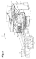
- An inkjet printer (a first embodiment), which is a multifunction apparatus having an image reading device for reading an image and is an embodiment of a liquid ejection apparatus for printing an image by ejecting ink as an example of liquid onto a sheet of paper as an example of medium, will first be described as an example of a liquid ejection apparatus, with reference to the attached drawings.
- a liquid container unit (a second embodiment) including a liquid container, which has an inlet for introducing ink that should be supplied to a liquid ejecting portion of a printer and a liquid containing portion for receiving the introduced ink, and a container holding body for holding the liquid container will be described with the attached drawings.
- an embodiment of a liquid container (a third embodiment) having an ink inlet and a liquid containing portion for receiving the ink introduced from the inlet will be described with the attached drawings.
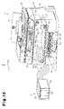
- a printer 11 is configured by an apparatus body 12 and a scanner unit 13 serving as an image reading device connected to and mounted on the apparatus body 12 at the trailing side in the direction of gravitational force (at an upper side) with respect to the vertical direction Z.
- the apparatus body 12 is configured by an apparatus casing 14, which is an example of a casing of the printer 11 configured by a plurality of components.
- a liquid ejecting portion 20 for ejecting ink onto a sheet of paper P is located in the space surrounded by the apparatus casing 14.
- a manipulation panel 15 which is manipulated by the user to operate the printer 11, is arranged at a front upper position in the discharging direction Y of a sheet of paper P after printing.
- the manipulation panel 15 includes a display portion (for example, a liquid crystal display) 15a for displaying a menu and the like and various manipulation buttons 15b, which are provided in the vicinity of the display portion 15a. Through manipulation of the manipulation buttons 15b, ejection by the liquid ejecting portion 20 is carried out to print an image.
- a front cover 16 which is a component of the apparatus casing 14, is attached to the apparatus casing 14 at a position below the manipulation panel 15 and selectively opened and closed.
- the front cover 16 covers an opening formed in the front side of the apparatus casing 14 and is opened forward about a pivot shaft 16J (see Fig. 5 ), which is formed in a lower portion of the front cover 16.
- a handle portion 16a which is held by the user to selectively open and close the front cover 16, is formed in the front cover 16 in a recessed manner.
- a paper outlet table 19, from which a sheet of paper P is discharged from the apparatus body 12 to the exterior of the apparatus body 12, is arranged below the front cover 16 in the apparatus casing 14.
- the printer 11 has a paper cassette 18, which is arranged below the paper outlet table 19 and accommodates multiple sheets of paper P in a stacked state.
- the stacked sheets of paper P are sent to a non-illustrated transport path formed in the apparatus body 12 one by one from the uppermost one and then transported to the liquid ejecting portion 20.
- the paper cassette 18 is detachable with respect to the apparatus body 12.
- a overhang-like handle portion 18a is formed in the front side of the paper cassette 18 and held by the user to detach the paper cassette 18 from the apparatus body 12, thus facilitating forward detachment of the paper cassette 18 from the apparatus body 12.
- a mounting tray 17 is arranged rearward to the apparatus body 12 to receive sheets of paper P.
- the sheets of paper P mounted on the mounting tray 17 are sent to a non-illustrated transport path formed in the apparatus body 12 and transported to the liquid ejecting portion 20.
- the liquid ejecting portion 20 includes a carriage 21 and a liquid ejection head 22.
- a guide shaft 23 is arranged in the apparatus casing 14 and extends in the widthwise direction X, which crosses the discharging direction Y of the sheets of paper P.
- the carriage 21 is supported to the guide shaft 23 in a manner displaceable in the widthwise direction X.
- a portion of the carriage 21 is fixed to a belt that moves as a non-illustrated carriage motor operates. As the belt moves, the carriage 21 reciprocates in the widthwise direction X, which is a scanning direction.
- the liquid ejection head 22 is supported to the lower side of the carriage 21 to eject ink as an example of liquid onto a sheet of paper P.
- a plurality of (four, in the first embodiment) ink cartridges 55 are arranged in a left end portion as viewed from front of the movement range of the carriage 21 in the widthwise direction X.
- the front cover 16 is opened and then each ink cartridge 55 is inserted into or removed from the cartridge holder 31 as guided by a guide portion 31a (see Fig. 2 ).
- the printer 11 has a first space SP1 to which supply needles 35 each serving as a supplying member, which supplies ink to the liquid ejecting portion 20, face.
- the first space SP1 is located in the space surrounded by the apparatus casing 14 including the front cover 16, which is an example of a lid member for covering the front opening.
- the first space SP1 is space for accommodating the cartridge holder 31, in which the ink cartridges 55 are inserted and mounted.
- a casing wall portion 14a, which is a portion of the apparatus casing 14, is formed at the right side in the first space SP1.
- a casing wall portion 14b, which is another portion of the apparatus casing 14, is arranged at the left side to the substrate unit 25.
- a second space SP3 is formed between the casing wall portions 14a, 14b in the space surrounded by the apparatus casing 14 including the front cover 16 covering the front opening.
- the second space SP3 is formed at a position outside the space occupied by the liquid ejecting portion 20 at the time when the liquid ejecting portion 20 ejects ink (prints), or, in other words, at a position above the movement range of the carriage 21.
- the second space SP3 is greater in volume than the first space SP1.
- Ink tanks 75 which are examples of liquid containers each including an inlet 77 through which ink is introduced, are inserted into the second space SP3 as represented by, for example, the arrows of lines formed by a long dash alternating with a short dash in Fig. 2 and thus received in the second space SP2. In this manner, the front opening of the apparatus casing 14 is arranged in correspondence with the ink cartridges 55 and the ink tanks 75.
- each of the ink tanks 75 has a great capacity compared to the capacity of each ink cartridge 55.
- the ink tanks 75 each contain the same type of ink as the corresponding one of the ink cartridges 55C, 55M, 55Y, and 55K.
- the ink tanks 75 include four ink tanks 75C, 75M, 75Y, and 75K, which are examples of liquid containers containing inks of the corresponding colors, which are cyan, magenta, yellow, and black.
- the four ink tanks 75C, 75M, 75Y, and 75K are formed either separately from or integrally with one another.
- the inlets 77 through which ink refill is introduced into the ink tanks 75C, 75M, 75Y, 75K, are formed in the upper sides of the ink tanks 75C, 75M, 75Y, 75K in the vertical direction Z, which crosses both the widthwise direction X and the discharging direction Y, or the trailing side in the direction of gravitational force.
- Each of the inlets 77 is normally closed by a non-illustrated lid and opened when ink is poured.
- Labels 76 are applied onto the front sides of the ink tanks 75C, 75M, 75Y, 75K, which are the sides facing the front cover 16 when the ink tanks 75C, 75M, 75Y, 75K are arranged in the second space SP3.
- the ink tanks are referred to simply as the ink tanks 75 when it is unnecessary to distinguish among the ink tanks 75C, 75M, 75Y, 75K.
- the ink tanks 75 are received in and held by a tank holder 72.
- the tank holder 72 is supported to a holder support table 71. Both the left end and the right end of the holder support table 71 are fixed to the apparatus casing 14 of the printer 11 (for example, the casing wall portion 14a and the casing wall portion 14b).
- the tank holder 72 is mounted in the printer 11 in a state supported to the holder support table 71 having the left and right ends fixed in the second space SP3.
- the ink tanks 75 are thus received in the second space SP3, or, in other words, the space surrounded by the apparatus casing 14.
- the holder support table 71 and the tank holder 72 each function as a container holding body for holding the ink tanks 75.
- the holder support table 71 is fixed to the apparatus casing 14 in a detachable manner.
- the holder support table 71 is thus removed for maintenance of the liquid ejecting portion 20, for example. This permits maintenance work related to sheets of paper P, including paper jamming, through the second space SP3.
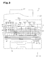
- the printer 11 thus has a liquid supply system EKS for supplying ink from the ink tanks 75 in the second space SP3 to the liquid ejecting portion 20 even when the ink cartridges 55C, 55M, 55Y, 55K are not mounted.
- the liquid supply system EKS will hereafter be described with reference to Figs. 3 and 4 .
- the drawings schematically show only components necessary for illustrative purposes.
- the liquid supply system EKS of the printer 11 supplies ink from the ink tanks 75C, 75M, 75Y, 75K to the liquid ejecting portion 20.
- the ink tanks 75C, 75M, 75Y, and 75K are connected to the supply needles 35 through connection tubes 78C, 78M, 78Y, and 78K, respectively, each of which is an example of an elastically deformable liquid supplying member.
- connection tubes 78C, 78M, 78Y, 78K each have an end connected to a supply port 78A located in the rear side of the corresponding ink tank 75 and another end connected to the corresponding supply needle 35 through the clearance between the cartridge holder 31 and the casing wall portion 14a.
- the connection tubes 78 Through such arrangement of the connection tubes 78, the ink contained in each ink tank 75 is supplied to the corresponding supply needle 35.
- the ink supplied to the supply needles 35 is delivered to the ink supply tubes 44 through a passage forming portion 40 functioning as liquid flow means mounted rearward to the cartridge holder 31.
- the passage forming portion 40 includes ink flow paths each having a side communicating with the corresponding supply needle 35, which is arranged forward to the passage forming portion 40, and another side communicating with the corresponding ink supply tube 44.
- Each of the flow paths includes a non-illustrated diaphragm pump and a non-illustrated check valve.
- the ink is caused to flow forcibly in an ink flow direction in which each supply needle 35 is arranged upstream and the corresponding ink supply tube 44 is located downstream.
- the passage forming portion 40 is thus located downstream in the ink flow direction heading from each supply needle 35 to the liquid ejecting portion 20.
- the passage forming portion 40 supplies the ink from the ink tanks 75 to the liquid ejecting portion 20 through the ink supply tubes 44, regardless of the location of each ink tank 75 in the second space SP3.
- the labels 76 which are applied onto the front sides of the ink tanks 75, are arranged such that the surface of each ink tank 75 is exposed on at least either the upper side or the lower side of the associated label 76.
- the labels 76 are arranged to expose both an upper surface portion 75a and a lower surface portion 75b of each ink tank 75. At least a portion of the upper surface portion 75a and the lower surface portion 75b is formed by a transparent (translucent) component that ensures visibility of the ink contained in the ink tank 75.
- the front cover 16 which is a component of the casing of the printer 11, includes a see-through region 16T serving as a visual check portion to ensure visibility of at least one the components including the labels 76, the upper surface portions 75a, and the lower surface portions 75b in a state where the front cover 16 is closed.
- the see-through region 16T is an opening formed in the front cover 16 such that the labels 76 and ensures visibility of the lower surface portions 75b of the ink tanks 75C, 75M, 75Y, 75K.
- the see-through region 16T may be formed using transparent (or translucent) material.
- the ink tanks 75 mounted in the second space SP3 of the printer 11 are displaceable in a forward direction, which is the discharging direction Y as represented by the blank arrow in Fig. 4 , from the state arranged in the printer 11.
- a movement mechanism is provided to move the ink tanks 75 such that the inlets 77 are delivered to positions outside the second space SP3. Examples (first to fifth examples) of the movement mechanism will hereafter be described with reference to Figs. 5 to 9 .
- the movement mechanism displaces the ink tanks 75 from the interior of the apparatus casing 14 to the exterior of the apparatus casing 14 through the opening such that a first portion including at least each inlet 77 is delivered to a position forward to the front cover 16.
- a movement mechanism 80A of the first example includes a rotary shaft 81 and a slide member 82.
- the rotary shaft 81 has a helical thread portion 81a, which is formed in the outer periphery of the rotary shaft 81.
- the slide member 82 includes a rack tooth portion 82a, which is meshed with the helical thread portion 81a, and two pillar portions 82b projected and spaced apart by a predetermined distance.
- the movement mechanism 80A also includes bar-like link members 83, 84, 85, which configure a link mechanism.
- the link member 84 pivots about a fixed shaft J1 fixed to the apparatus casing 14 and the link member 85 pivots about a fixed shaft J2 also fixed to the apparatus casing 14.
- the fixed shafts J1, J2 are spaced from each other by a predetermined distance in the forward-rearward direction.
- the link member 83 is linked through a pivot shaft 84a provided at an end of the link member 84 and a pivot shaft 85a provided at the corresponding end of the link member 85.
- the pivot shafts 84a, 85a are arranged at positions where, when the link member 83 moves in the forward-rearward direction, the link member 84 and the link member 85 pivot while being maintained in a parallel state.
- the link member 83 has a projection 83a, which is formed at an end (in this example, a rear end) of the link member 83.
- the projection 83a is arranged between the two pillar portions 82b of the slide member 82 and thus moved together with the slide member 82.
- the link member 84 has a pivot shaft 84b, which is provided at the end opposite to the end connected to the link member 83.
- the pivot shaft 84b is connected to the tank holder 72.
- the link member 85 has a pivot shaft 85b, which is provided at the end opposite to the end connected to the link member 83.
- the pivot shaft 85b is connected to the tank holder 72.
- the rotary shaft 81 is rotated by a non-illustrated drive source, which is activated either automatically or manually by the user, at the time when the front cover 16 is in an open state where the opening is exposed.
- This moves the slide member 82 in the forward-rearward direction.
- the link mechanism is activated by the slide member 82 moving from a front position to a rear position, thus moving the tank holder 72 forward.
- the first portion of each ink tank 75 including the inlet 77 is displaced from the interior of the apparatus casing 14 to the exterior of the apparatus casing 14 through the opening.
- the movement mechanism 80A of the first example is configured in this manner.
- a movement mechanism 80B of the second example has a lever member 16L and a tank holder 72B.
- the lever member 16L pivots about a pivot shaft 16J integrally with the front cover 16 and includes a round pin 16P, which is formed at the opposite end to the end corresponding to the pivot shaft 16J.
- the tank holder 72B has an engagement hole 72H, which is formed in a front end portion of the tank holder 72B and engaged with the round pin 16P.
- the front cover 16 is manipulated by the user to switch to an open state in which the opening is exposed.
- the lever member 16L is rotated about the pivot shaft 16J and thus moved from a rear position to a front position as represented by the solid lines and the broken lines in which a long dash alternates with a pair of short dashes in Fig. 6 .
- the lever member 16L moves the engagement hole 72H, which is engaged with the round pin 16P, to a front position.
- the movement mechanism 80B of the second example is configured in this manner.
- connection tubes 78 connected to the supply ports 78A of the ink tanks 75 are each formed by an elastically deformable tube.
- Each of the connection tubes 78 has a curved portion 78W, which is formed in at least a portion of the connection tube 78 and curved in a normal state, or, in other words, a state substantially free from stress.
- each connection tube 78 is displaced from a front position to a rear position with respect to the ink tank 75 without receiving much stress.
- a movement mechanism 80C of the third example has a tank holder 72C, which is formed substantially in an L shape as viewed in the widthwise direction X, and a holder support table 71C.
- the tank holder 72C supports the ink tanks 75 at least in the forward-rearward direction.
- Rollers 71R are provided on the upper side of the holder support table 71C.
- the tank holder 72C is mounted on the holder support table 71C through the rollers.
- a handle 72T is provided in a front portion of the tank holder 72C and held by the user to easily move the tank holder 72C on the holder support table 71C in the forward-rearward direction.
- An engagement groove 72K having a substantially triangular cross section is provided in the bottom surface of the tank holder 72C.
- An engagement piece 71K having a substantially triangular cross section which projects from the top surface of the holder support table 71C in a displaceable manner, enters the engagement groove 72K. This permits rearward movement of the tank holder 72C and restricts the amount of forward movement of the tank holder 72C.
- a window hole 72M which ensures visibility of the labels 76 applied onto the ink tanks 75, is formed in the front portion of the tank holder 72C. This allows the user to view the ink tanks 75 when drawing the ink tanks 75. Accordingly, in the third example, the interior of the tank holder 72C may be divided into four sections in the widthwise direction X of the sheet of paper P. In this case, the user may separately view and draw the ink tanks 75C, 75M, 75Y, 75K.
- the tank holder 72C when the front cover 16 is in an open state where the opening is exposed, the tank holder 72C is displaceable in the forward-rearward direction through manipulation by the user. As represented by the solid lines and the broken lines in which a long dash alternates with a pair of short dashes in Fig. 7 , by moving the tank holder 72C from a rear position to such a front position that the amount of forward movement of the tank holder 72C is restricted, the first portion of each ink tank 75 including the inlet 77 is displaced from the interior of the apparatus casing 14 to the exterior of the apparatus casing 14 through the opening.
- the movement mechanism 80C of the third example is configured in this manner.
- each ink tank 75 includes two conductive members 61 each having an end 61a inserted into a corresponding ink chamber 75S, which is an example of a liquid containing portion.
- a casing member 14c of the apparatus casing 14 includes two conductive terminals 62, each of which is electrically connected to the substrate unit 25 and includes opposing curved conductive portions 62a. Each conductive terminal 62 is fixed in a cantilevered state such that the side corresponding to the conductive portions 62a can flex.
- Each conductive terminal 62 clamps the corresponding conductive member 61 by means of the opposing conductive portions 62a.
- Each conductive member 61 extends in the forward-rearward direction and has such a length that, even when the conductive member 61 moves in the forward-rearward direction together with the ink tank 75, the conductive member 61 is maintained in the state clamped by the conductive portions 62a.
- the ink tank 75 moves to a front position to displace the first portion including the inlet 77 from the interior of the apparatus casing 14 to the exterior of the apparatus casing 14 through the opening as represented by the solid lines and the broken lines in which a long dash alternates with a pair of short dashes in Fig.
- each conductive member 61 and the corresponding conductive terminal 62 is constantly maintained. That is, the conductive members 61 and the conductive terminals 62 each function as an electric connecting portion that ensures electric connection between the corresponding ink tank 75 and the apparatus casing 14.
- the conductive terminals 62 may be provided in the ink tanks 75 and the conductive members 61 may be arranged in the casing member 14c.
- the end 61a electrically connected to the corresponding conductive terminal 62 is inserted into and mounted in each ink chamber 75S, which is an example of a liquid containing portion.
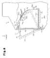
- a movement mechanism 80D of the fourth example includes a tank holder 72D and ink tanks 75 each having an arcuate portion.
- the tank holder 72D is, for example, formed integrally with the front cover 16 and rotated about the pivot shaft 16J of the front cover 16 integrally with the front cover 16.
- Each ink tank 75 has such a shape (in the fourth example, a substantially arcuate shape) that the ink tank 75 is displaceable from the position corresponding to the opening, which is covered by the front cover 16, to a front position when rotated about the pivot shaft 16J.
- the ink tanks 75 held by the tank holder 72D are rotated about the pivot shaft 16J from a rear position to a front position as represented by the solid lines and curves and the broken lines in which a long dash alternates with a pair of short dashes and curves in Fig. 8 .
- the front cover 16 is rotated toward the open state by a predetermined angle, the first portion of each ink tank 75 including the inlet 77 is displaced from the interior of the apparatus casing 14 to the exterior of the apparatus casing 14 through the opening.
- a non-illustrated pivot angle determining portion positions the tank holder 72D when the inlets 77 are moved to the exterior of the apparatus casing 14.
- the movement mechanism 80D of the fourth example is configured in this manner.
- each ink tank 75 has the conductive board 63 having an end 61a inserted into the ink chamber 75S, which is an example of a liquid containing portion.
- the conductive board 63 is shaped in correspondence with the arcuate shape of the ink tank 75 and fixed.
- the conductive terminal 64 which is electrically connected to the substrate unit 25 and has an angled conductive portion 64a, is fixed in the apparatus casing 14 in a cantilevered manner to flex the side corresponding to the conductive portion 64a.
- the conductive terminal 64 contacts the conductive board 63 through the conductive portion 64a.
- Each conductive board 63 extends in a manner following the arcuate shape of the ink tank 75 and has such a length that, even when rotated in the forward-rearward direction together with the ink tank 75, the conductive board 63 is maintained in contact with the conductive portion 64a.
- the ink tank 75 moves forward to displace the first portion including the inlet 77 from the interior of the apparatus casing 14 to the exterior of the apparatus casing 14 through the opening as represented by the solid lines and curves and the broken lines in which a long dash alternates with a pair of short dashes and curves in Fig.
- Fig. 8 electric connection between the conductive board 63 and the conductive terminal 64 is constantly maintained.
- the conductive board 63 and the conductive terminal 64 thus function each as an electric connecting portion that ensures electric connection between the ink tank 75 and the apparatus casing 14.
- Fig. 8 includes the single conductive board 63 and the single conductive terminal 64, a plurality of conductive boards 63 and a plurality of conductive terminals 64 may be employed and aligned in the widthwise direction X, for example.
- connection tube 78 connected to the ink tank 75 may be formed by an elastically deformable tube.
- the curved portion 78W (see Fig. 6 ), which is curved in a normal state, may be formed in at least a portion of the connection tube 78.
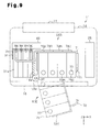
- a movement mechanism 80E of the fifth embodiment includes a tank holder 72E having a pivot portion 72R, which pivots about a pivot shaft 37.
- the pivot shaft 37 is provided in the casing wall portion 14a and has an axis extending in the vertical direction.
- the holder support table 71 is mounted not to interfere with the tank holder 72E at the time when the tank holder 72E pivots about the pivot shaft 37.
- the movement mechanism 80E of the fifth embodiment pivots the ink tanks 75, which are held by the tank holder 72E, about the pivot shaft 37 from a rear position to a front position as represented by the solid lines and the broken lines in which a long dash alternates with a pair of short dashes in Fig. 9 .
- This displaces the first portion of each ink tank 75 including the inlet 77 from the interior of the apparatus casing 14 to the exterior of the apparatus casing 14 through the opening.
- the opening covered by the front cover 16 is sized to permit the ink tanks 75 to pivot to move the inlet 77 to positions outside the apparatus casing 14.
- the movement mechanism 80E of the fifth embodiment is configured in this manner.
- the movement mechanism is activated by the user when it is visually determined that the remaining amount of ink in any one of the ink tanks 75 is small due to, for example, ink consumption through the see-through region 16T of the front cover 16 in the closed state.
- the ink tanks 75 are moved from the rear position to the front position by rotating the front cover 16 or moving the tank holder 72 after having rotated the front cover 16. This ejects the ink tanks 75 forward through the opening, which is exposed by rotating the front cover 16.
- the first portion of each ink tank 75 including the inlet 77 is arranged outside the apparatus casing 14 of the printer 11 with the inlet 77 held in a visible state through the opening. Specifically, when each inlet 77 is visible, ink can be poured into the inlet 77.
- each ink tank 75 must be accommodated in the second space SP3.
- the whole or a portion of the ink tank 75 may be received in the second space SP3.
- the engagement groove 72K having a substantially triangular cross section may be formed in the bottom surface of each ink tank 75.
- a portion of the ink tank 75 is engaged with the engagement piece 71K and the other portions of the ink tank 75 are located outside the second space SP3.
- a pivot portion rotating about the pivot shaft 16J may be arranged on the bottom surface of each ink tank 75.
- the portions of the ink tank 75 other than the pivot portion are arranged outside the second space SP3.
- the pivot portion 72R may be provided in a portion of each ink tank 75. In this case, the portions of the ink tank 75 other than the pivot portion 72R are located outside the second space SP3.
- the first embodiment has the advantages described below.
- a liquid container unit according to a second embodiment of the present invention will now be described.
- the same or like reference numerals are given to components of the second embodiment that are the same as or like corresponding components of the printer 11 of the first embodiment. Description of these components is omitted herein when unnecessary.
- a tank unit 70 which is an example of a liquid container unit, includes ink tanks 75 each having an ink inlet 77, each of which is an example of liquid container, and a tank casing 79 holding the ink tanks 75, which is an example of a container holding body.
- the tank casing 79 is shaped substantially like a box having an opening formed in one side.
- the ink tanks 75 are inserted through the opening to be held in the tank casing 79 with the inlets 77 each maintained in a non-exposed state.
- the tank unit 70 supplies ink from the ink tanks 75 to the printer 11 through corresponding connection tubes 78, each of which is connected to the supply port 78A of the corresponding ink tank 75 held in the tank casing 79.
- the tank casing 79 has a structure for holding the ink tanks 75 in a state where at least the first portion of each ink tank 75 including the inlet 77 is displaceable relative to the tank casing 79. Examples (first to third examples) of the holding structure will hereafter be described with reference to Figs. 11 to 15 .
- the tank unit 70 is illustrated in a state where the opening of the tank casing 79 faces in the discharging direction Y for illustrative purposes.
- relative displacement refers to absolute difference in position between a certain point and another in a structure.
- first portion of each ink tank 75 may be displaceable while the tank casing 79 is not displaceable.
- first portion of each ink tank 75 may be immovable while only the tank casing 79 is displaceable.
- the first portion of each ink tank 75 and the tank casing 79 both may be displaceable.
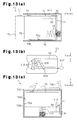
- the holding structure of the first example holds each ink tank 75 in a manner linearly displaceable in the discharging direction Y, in which the opening of the tank casing 79 faces, to minimize the distance covered by movement of the inlet 77 from the interior of the tank casing 79 (from inside the tank casing 79) to the exterior of the tank casing 79 (to outside the tank casing 79).
- an elongated projection 75D is projected from the bottom surface of each ink tank 75 and extends in the discharging direction Y.
- a groove 79D is formed in the inner lower side of the tank casing 79 and extends in the discharging direction Y.
- the elongated projection 75D thus slides in the groove 79D functioning as a guide rail to position the lower end of the ink tank 75 in the widthwise direction X and linearly move the ink tank 75 in the discharging direction Y.
- Guide ribs 79a project from the inner upper side of the tank casing 79 and extend in the discharging direction Y.
- the guide ribs 79a stop the upper end of the ink tank 75 from inclining in the widthwise direction X when the ink tank 75 moves in the discharging direction Y.
- overhang portions 75F are formed in the upper end portion of each ink tank 75 and projected toward the opposite sides of the widthwise direction X.
- Corresponding guide ribs 79b project from the inner upper side of the tank casing 79 and extend in the discharging direction Y.
- the distal end portion of each guide rib 79b contacts the corresponding overhang portion 75F, which functions as a guide rail, from below.
- the overhang portions 75F thus slide on the corresponding guide ribs 79b to position each ink tank 75 in the widthwise direction X and allow linear movement of the ink tank 75 in the discharging direction Y.
- the elongated projection 75D projects from the bottom surface of the tank casing 79 and extends in the discharging direction Y.
- the groove 79D is formed in the inner lower side of the tank casing 79 and extends in the discharging direction Y.
- the elongated projection 75D is received in the groove 79D to stop the lower end of the ink tank 75 from inclining in the widthwise direction X.
- the tank unit 70 of the first example includes a conductive board 63 and a conductive terminal 64, as illustrated in Fig. 11 .
- the conductive board 63 and the conductive terminal 64 both function as an electric connecting portion between the tank casing 79 and the ink tank 75.
- the conductive board 63 is fixed to the top side of the ink tank 75 and elongated in the discharging direction Y.
- An electrically connected end portion 61a of the conductive board 63 is inserted into the ink chamber 75S.
- the conductive terminal 64 which includes a conductive portion 64a held in contact with the conductive board 63, is fixed to the inner upper side of the tank casing 79 in a cantilevered manner to flex the side corresponding to the conductive portion 64a.
- the electric connection between the conductive board 63 and the conductive terminal 64 is thus constantly maintained even when the ink tank 75 is moved forward to displace the first portion of the ink tank 75 including the inlet 77 to a position outside the tank casing 79, as represented by the solid lines and the broken lines in which a long dash alternates with a pair of short dashes in Fig. 11 .
- connection tube 78 connected to each ink tank 75 is formed by an elastically deformable tube having the curved portion 78W, which is formed in at least a portion of the tube and curved in a normal state. Accordingly, as represented by the solid lines and the broken lines in which a long dash alternates with a pair of short dashes in Fig. 11 , the connection tube 78 is allowed to be displaced with limited stress as the ink tank 75 moves from the interior of the tank casing 79 to the exterior in the discharging direction Y.
- the holding structure of the first example may hold each ink tank 75 to allow at least the first portion of the ink tank 75 including the inlet 77 to be displaced relative to the tank casing 79 after the ink tank 75 moves in the opposite direction to the movement direction (the discharging direction Y) in which the inlet 77 moves from the interior of the tank casing 79 to the exterior of the tank casing 79.
- each ink tank 75 in the tank casing 79 is urged in the discharging direction Y by an urging member CS such as a coil spring.
- a positioning mechanism 90 restricts movement of the ink tank 75 in the discharging direction Y against such urging to position the ink tank 75.
- the positioning mechanism 90 includes an engagement member 91 and an engaged portion 92. An end of the engagement member 91 is configured to be pivoted and supported to the tank casing 79. A columnar pin 91P is formed on another end of the engagement member 91.
- the engaged portion 92 includes a predetermined uneven shape.
- the uneven shape formed in the engaged portion 92 defines a movement path in which the columnar pin 91P of the engagement member 91 is allowed to move repeatedly.
- the columnar pin 91P is moved in the movement path relative to the ink tank 75 as represented by the corresponding solid arrow in Fig. 13(b) .
- the ink tank 75 When the columnar pin 91P is held in contact with the side of a projected portion 92B of the engaged portion 92 in the discharging direction Y as represented by the solid circle in Fig. 13(b) , the ink tank 75 is held in a state in which the inlet 77 is not exposed, which is a normal use state in which the inlet 77 is located inside the tank casing 79. In this state, by pressing the ink tank 75 in the opposite direction to the discharging direction Y, which is the opposite direction to the urging direction of the urging member CS, the ink tank 75 is retracted to the position represented by the broken line formed by a long dash alternating with a short dash in Fig. 13(a) .
- the columnar pin 91P moves from the position represented by the circle of a broken line in which a long dash alternates with a pair of short dashes in Fig. 13(b) and proceeds along a slope portion 92A as represented by the corresponding solid arrow. In this manner, the columnar pin 91P is positioned at the position corresponding to the normal use state represented by the solid circle in Fig. 13(b) .
- the holding structure of the first example may be employed not only in a case in which each ink tank 75 of the tank unit 70 linearly moves in the discharging direction Y, but also in a case where the ink tank 75 linearly moves in the upward-downward direction, which is the vertical direction.
- each ink tank 75 linearly displaceable in the upward-downward direction is accommodated in a tank casing 79B, which is shaped like a box having an upper opening in the vertical direction Z.
- the ink tank 75 is disengaged from the engagement member 91 of the positioning mechanism 90 and raised by the urging member CS from the position represented by the solid lines in Fig. 13(c) to the position represented by the broken lines in which a long dash alternates with a pair of short dashes in the drawing.
- Such rise of the ink tank 75 moves the inlet 77 to the exterior of the tank casing 79B.
- the casing cover 79C may, for example, swing to expose the opening of the tank casing 79B.
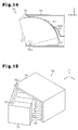
- the holding structure of the second example holds each ink tank 75 in the tank casing 79 to allow the ink tank 75 to rotate, or swing, about a pivot shaft 75J, which is configured to be pivoted and supported at an opening end of the inner bottom of the tank casing 79, with the widthwise direction X serving as the axis of pivot.
- the ink tank 75 is formed including an arcuate portion, for example, and shaped in a manner displaceable without interfering with the tank casing 79 when rotating about the pivot shaft 75J (in this example, shaped to have a sectoral cross section).
- the holding structure of the second example pivots the ink tank 75 about the pivot shaft 75J from a rear position to a front position in the discharging direction Y, as represented by the solid lines and curve and the broken lines in which a long dash alternates with a pair of short dashes and curve in Fig. 14 .
- This displaces the first portion of the ink tank 75 including the inlet 77 to a position outside the tank casing 79.
- a non-illustrated pivot angle defining portion positions the ink tank 75 after the inlet 77 is moved to the exterior of the tank casing 79.
- a conductive board 63 and a conductive terminal 64 may be arranged between the tank casing 79 and the ink tank 75.
- the conductive board 63 is fixed to the ink tank 75 and shaped in correspondence with the arcuate shape.
- the conductive terminal 64 which includes an angled conductive portion 64a, is fixed to the tank casing 79 in a cantilevered manner to flex the side including the conductive portion 64a.
- Electric connection is thus constantly maintained between the conductive board 63 and the conductive terminal 64 even after the ink tank 75 is rotated forward to displaced the first portion including the inlet 77 to a position outside the tank casing 79, as represented by the solid lines and curve and the broken lines in which a long dash alternates with a pair of short dashes and curve in Fig. 14 .
- connection tube 78 having the curved portion 78W which is curved in a normal state, communicates with the ink tank 75 through the supply port 78A of the ink tank 75 in the tank unit 70 including the holding structure of the second example.
- the positioning mechanism 90 also may be employed.
- the holding structure of the third example holds each ink tank 75 in the tank casing 79 to allow the ink tank 75 to pivot, or swing, horizontally about the pivot shaft 75J, which is configured to be pivoted and supported at an opening end of the tank casing 79 in the widthwise direction X, with the axis of pivot extending in the vertical direction.
- the tank casing 79 has such a dimension in the widthwise direction X that the ink tanks 75 do not interfere with the tank casing 79 when the ink tanks 75 swing.
- the holding structure of the third example pivots the ink tanks 75 about the pivot shaft 75J from a rear position to a front position in the discharging direction Y as illustrated in Fig. 15 .
- This displaces the first portion of each ink tank 75 including the inlet 77 to the exterior of the tank casing 79.
- a non-illustrated pivot angle defining portion positions the ink tanks 75 after the inlets 77 are moved to the exterior of the tank casing 79.
- connection tube 78 connected to the supply port 78A of the corresponding ink tank 75 may have the curved portion 78W, which is curved in a normal state, in the tank unit 70 having the holding structure of the third example.
- the positioning mechanism 90 also may be employed as needed.
- tank unit 70 of the second embodiment including the holding structure for the ink tanks 75 will hereafter be described.
- the user moves the ink tanks 75 when it is visually determined that the remaining amount of ink in any one of the ink tanks 75 in the tank casing 79 is small due to, for example, ink consumption through the upper surface portion 75a or the lower surface portion 75b with respect to the associated label 76 (see Fig. 3 ).
- the ink tanks 75 are moved from the rear position to the front position through linear movement or rotation from the tank casing 79. This exposes the first portion of each ink tank 75 including the inlet 77 to the exterior of the tank casing 79 in a state where the first portion is visible from above, for example.
- the second embodiment has the advantages described below.
- a liquid container according to a third embodiment of the present invention will now be described.
- the same or like reference numerals are given to components of the third embodiment that are the same as or like corresponding components of the printer 11 of the first embodiment and corresponding components of the tank unit 70 of the second embodiment. Description of these components is omitted herein when unnecessary.
- each ink tank 75 includes the ink inlet 77, the ink chamber 75S serving as a liquid containing portion for receiving the ink introduced from the inlet 77, and the supply port 78A connected to a liquid supplying member connected to the liquid ejection head of the printer 11.
- the ink tank 75 has a displacing structure for displacing the first portion of the ink tank 75 including the inlet 77 relative to a second portion of the ink tank 75 that is separate from the first portion and includes the ink chamber 75S. Examples (first to third examples) of the displacing structure will now be described with reference to Figs. 16 to 19 .
- the ink tank 75 is oriented with the inlet 77 located forward in the discharging direction Y for illustrative purposes.
- the discharging direction Y in the third embodiment refers to the direction in which the first portion of each liquid container including the inlet 77 for receiving ink is displaced when the liquid container, which will be described below, is mounted in the printer 11 or the tank casing 79.
- the displacing direction may be any suitable direction as long as ink can be introduced into the inlet 77 after the first portion is displaced in this direction. The displacing direction is thus not restricted to the discharging direction Y in the drawings.
- a displacing portion 77h which is the first portion of the ink tank 75 including the inlet 77, is mounted in a state slidable in the discharging direction Y relative to a tank body portion 75h, which is the second portion of the ink tank 75 that is separate from the first portion.
- a connection tube 97 is arranged between the displacing portion 77h and the tank body portion 75h as an example of a tube through which ink flows from the inlet 77 to the ink chamber 75S, which is formed in the tank body portion 75h.
- the displacing structure of the first example displaces the displacing portion 77h such that the inlet 77 linearly moves in the discharging direction Y.
- ink is introduced from the inlet 77 into the ink chamber 75S through the connection tube 97.
- the displacing structure of the first example may be configured by a plurality of (in this case, two) displacing portions 77h, 77g through which the first portion of each ink tank 75 including the inlet 77 slides in the discharging direction Y relative to the tank body portion 75h, which is the second portion separate from the first portion.
- the connection tube 97 is arranged between the displacing portion 77h and the tank body portion 75h to permit ink flow from the inlet 77 into the ink chamber 75S in the tank body portion 75h.
- the displacing portion 77h and the displacing portion 77g are linearly displaceable in the discharging direction Y. From the displaced state, the inlet 77 is displaced by an additional distance in the discharging direction Y.
- the movement direction of the displacing portion 77h may be different from the movement direction of the displacing portion 77g.
- the displacing structure may linearly move the displacing portion 77g upward in the vertical direction Z and then linearly move the displacing portion 77h in the discharging direction Y.
- the displacing portion 77g and the displacing portion 77h may be displaceable independently from each other.
- the displacing portion 77h which is the first portion including the inlet 77, is displaced in a manner extending from the tank body portion 75h, which is the second portion separate from the first portion.
- the displacing portion 77h is configured by a plurality of (in the drawing, three) components, which are displaceable relative to one another.
- the components which are a first member 77a, a second member 77b, and a third member 77c, serve as the first portion of the ink tank 75 including the inlet 77.
- the displacing portion 77h is displaced in a manner popping up from the tank body portion 75h through relative movement of the first member 77a, the second member 77b, and the third member 77c relative to one another.
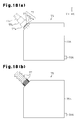
- the displacing portion 77h including the inlet 77 may be formed by a bellows-like tube having an extensible pleated portion. Specifically, as represented by the solid lines and the broken lines in which a long dash alternates with a pair of short dashes in Fig. 18(a) , the displacing portion 77h is displaced in a manner projecting from the tank body portion 75h through extension of the pleated portion.
- the displacing portion 77h which is the first portion of each ink tank 75 including the inlet 77, is attached to the tank body portion 75h, which is the second portion separate from the first portion, in a state in which the inlet 77 is not exposed.
- the displacing portion 77h is mounted on the front side of the tank body portion 75h, which is located forward in the discharging direction Y.
- the displacing portion 77h is displaced by rotating about the axis located downward in the vertical direction Z, or, in other words, forward in the direction of gravitational force, such that an upper portion of the displacing portion 77h moves forward in the discharging direction Y.
- the displacing portion 77h is displaced by moving linearly in the discharging direction Y. This also exposes the inlet 77 such that ink can be introduced from the inlet 77 into the ink chamber 75S.
- the inlet 77 is displaced by the user when, for example, it is visually determined that the remaining amount of ink in any one of the ink tanks 75 is small through the upper surface portion 75a or the lower surface portion 75b (see Fig. 3 ) with respect to the associated label 76. Specifically, the inlet 77 is moved through linear movement or rotation. This exposes the inlet 77 such that ink can be poured into the inlet 77 and thus locates the inlet 77 at a position where ink is easily introduced into the inlet 77.
- the third embodiment has the advantages described below.
- the third embodiment may be modified to the forms described below.
- each ink tank 75 may include a plurality of inlets 77.
- each ink tank 75 may have a plurality of ink chambers 75S.
- each ink tank 75 may have two inlets 77A, 77B.
- an ink chamber 75SA is formed in correspondence with the inlet 77A and an ink chamber 75SB is arranged in correspondence with the inlet 77B.
- the inlet 77A and the inlet 77B are located close to each other in the discharging direction Y at positions close to either end (in the drawing, the end forward in the discharging direction Y) of the ink tank 75.
- This arrangement may be brought about by, for example, dividing a single ink chamber into the ink chamber 75SA and the ink chamber 75SB using a partition plate 75P, which is received in the tank body portion 75h in a diagonally inclined state.
- two inlets 77A, 77B may be formed in the displacing portion 77h of each ink tank 75.
- the inlets 77A, 77B are displaced away from the tank body portion 75h of the ink tank 75 in the discharging direction Y.
- the two inlets 77A, 77B of the displacing portion 77h may be aligned in the widthwise direction X, which crosses the discharging direction Y.
- the inlets 77A, 77B are displaced away from the tank body portion 75h of the ink tank 75 in the discharging direction Y by equal distances.
- the ink tank 75 having the multiple inlets 77 may be employed in the printer 11 of the first embodiment. If the printer 11 of the first embodiment has the ink tank 75 having the two inlets 77A, 77B, for example, it is preferable to arrange the inlets 77A, 77B each at a position where the inlets 77A, 77B can be displaced to the exterior of the apparatus casing 14 by moving the ink tank 75.
- the modified forms of the third embodiment have the advantage described below. (19) In the printer 11, the inlets 77A, 77B are moved to the exterior of the apparatus casing 14. The inlets 77A, 77B are thus displaced to positions where ink is easily poured into the inlets 77A, 77B.
- the ink tank 75 having the multiple inlets 77 (77A, 77B), as in the modified forms of the third embodiment, may be employed in the printer 11 of the second embodiment. If the printer 11 of the second embodiment has the ink tank 75 having the aforementioned two inlets 77A, 77B, for example, it is preferable to arrange the inlets 77A, 77B each at a position where the inlets 77A, 77B can be moved to the exterior of the tank casing 79 by displacing the ink tank 75 relative to the tank casing 79.
- This modified form has the advantage described below.
- the ink tanks 75 of the third embodiment may be employed in the printer 11 of the first embodiment.
- the ink tanks 75 illustrated in Fig. 2 may be replaced by the ink tanks 75 illustrated in any one of Figs. 16 , 17 , 18 , and 19 .
- This configuration includes the ink tanks 75 each having a displaceable ink inlet 77.
- the printer 11 is thus allowed to displace the inlets 77 to positions where ink is easily introduced from the inlets 77.
- the printer 11 does not necessarily have to have the movement mechanism (80A to 80E) for the ink tanks 75.
- the tank unit 70 of the second embodiment may be employed in the printer 11 of the first embodiment.
- This configuration includes the tank unit 70 in which the ink inlets 77 can be displaced.
- the printer 11 is thus allowed to displace the inlets 77 to positions where ink is easily introduced from the inlets 77.
- the printer 11 does not necessarily have to have the movement mechanism (80A to 80E) for the ink tanks 75.
- the tank casing 79 of the second embodiment may be replaced by the tank holder 72 mounted in the space surrounded by the apparatus casing 14 of the first embodiment.
- the tank unit 70 illustrated in any one of Figs. 13(a) , 14, and 15 may be replaced by the tank holder 72, the ink tanks 75, and the movement mechanism 80A illustrated in Fig. 5 .
- the structure for moving the first portion of each ink tank 75 is simplified.
- the casing of the printer 11 is thus reduced in size.
- the tank unit 70 illustrated in Fig. 13(c) may be replaced by the tank holder 72, the ink tanks 75, and the movement mechanism 80A illustrated in Fig. 5 .
- a scanner unit 13 is employed as in the case of the printer 11 illustrated in Fig. 1 .
- the top surface of the tank unit 70 is exposed by opening a scanner unit 70.
- the ink tanks 75 are pressed downward to cause the urging member CS to raise the ink tanks 75.
- This moves the first portion of each ink tank 75 to displace the inlet 77 to a position where ink is easily poured into the inlet 77.
- the structure for moving a portion of the ink tank 75 is simplified. The size of the casing of the printer 11 is thus reduced.
- the inlet 77 of each ink tank 75 does not necessarily have to be displaced to the exterior of the tank casing 79 as long as the inlet 77 is arranged at a position where ink can be poured into the inlet 77.
- the inlet 77 if at least a portion of the inlet 77 is moved to a position outside the tank casing 79, the inlet 77 is considered to be arranged at a position in the exterior of the tank casing 79.
- the inlet 77 of each ink tank 75 does not necessarily have to be arranged inside the tank casing 79 when the inlet 77 is in a state in which ink is not introduced (a normal use state).
- the holding structure for the ink tanks 75 may move each inlet 77 relative to the tank casing 79 to move the inlet 77 from a position at which ink introduction into the inlet 77 is difficult to a position at which ink is easily introduced into the inlet 77.
- the front cover 16 does not necessarily have to include the see-through region 16T serving as the visual check portion. It is not particularly necessary to check the ink remaining amount through the see-through region if ink refill is supplied to the ink tanks 75 periodically.
- the medium is not restricted to the sheet of paper P but may be a plate-like member formed by a metal plate, a plastic plate, or fabric.
- any other suitable object can be used as the medium as long as the object can be transported and subjected to printing using the ink ejected by the liquid ejecting portion 20.
- the liquid ejecting portion 20 is not restricted to the liquid ejecting portion of a serial type printer in which the liquid ejection head 22 reciprocates integrally with the carriage 21. That is, the liquid ejecting portion 20 may be the liquid ejecting portion of a line head type printer in which the liquid ejection head 22 is maintained in a fixed state even to perform printing at the maximum paper size.
- the printer 11 may be a printer without a scanner unit 13 or a multifunction apparatus having the liquid ejecting portion 20 and functioning as a facsimile machine or a copier.
- the liquid ejection apparatus is embodied as the inkjet type printer 11, which has a liquid ejection head for ejecting ink.
- the liquid ejection apparatus may be embodied as a liquid ejection apparatus for ejecting or discharging any other suitable type of liquid than ink.
- various types of liquid ejection apparatuses including a liquid ejection head for ejecting droplets of minute amount of liquid may employ the present invention.
- the liquid droplets refer to a form of liquid discharged by the liquid ejection apparatus and include ones of round shapes, or tear drop shapes, and ones with string-like tails.
- the liquid herein may be any suitable material as long as the liquid ejection apparatus can eject the material.
- the material must be in a liquid phase and includes liquefied matter with high or low viscosity, as well as material with fluidity such as sol, gel water, other types of inorganic solvent, organic solvent, solution, liquid resin, or liquid metal (molten metal).
- the liquid includes not only the liquid as one form of material but also functional material particles formed by solid such as pigment or metal particles dissolved, dispersed, or mixed in solvent.
- Typical examples of the liquid include liquid crystal and ink as has been described for the illustrated embodiments.
- the ink herein includes various types of liquid compositions such as typical water-based, oil-based, and gel inks and hot melt ink.
- the liquid ejection apparatus examples include a liquid ejection apparatus for ejecting liquid containing material such as electrode material or color material, which is used to manufacture a liquid crystal display, an electroluminescence display (an EL display), a surface light emitting display, or a color filter, in a dispersed or dissolved form.
- the liquid ejection apparatus may be a liquid ejection apparatus for ejecting biological organic matter used to manufacture biochips, a liquid ejection apparatus employed as a precision pipette to eject liquid serving as sample, a textile printing device, or a microdispenser.
- the liquid ejection apparatus may be a liquid ejection apparatus for ejecting lubricant oil into a precision machine such as watches, clocks, and cameras with precision, a liquid ejection apparatus for ejecting transparent liquefied resin such as ultraviolet curable resin onto a substrate to form a micro hemispherical lens (an optical lens) used as an optical communication element, or a liquid ejection apparatus for ejecting acid or alkaline etching liquid onto a substrate for etching.
- the present invention may be employed in anyone of the liquid ejection apparatuses listed above. Description of the Reference Numerals
- 11...printer an example of a liquid ejection apparatus
- 14...apparatus casing an example of a casing
- 15...manipulation panel 16...front cover (an example of a lid member)
- 20...liquid ejecting portion 22...liquid ejection head
- 70...tank unit an example of a liquid container unit
- 75...ink tank an example of a liquid container
- 75S...ink chamber an example of a liquid containing portion
- 77, 77A, 77B...inlet an example of a liquid containing portion
- 78...connection tube an example or a liquid supplying member or a tube
- 78A...supply port 78W...curved portion
Landscapes
- Ink Jet (AREA)
- Details Of Rigid Or Semi-Rigid Containers (AREA)
- Containers And Packaging Bodies Having A Special Means To Remove Contents (AREA)
Abstract
Description
- The present invention relates to a liquid container for containing liquid, which will be supplied to a liquid ejection head for ejecting liquid, a liquid container unit for holding the liquid container, and a liquid ejection apparatus having a liquid ejection head for ejecting liquid.
- Conventionally, liquid ejection apparatuses for printing images including characters and graphics on a sheet of paper serving as an example of medium by ejecting ink, which is an example of liquid, from a liquid ejection head onto the sheet of paper are used. One such apparatus supplies ink to a liquid ejection head, which ejects ink, from an ink cartridge (a liquid container) containing ink through a connection tube connected to the ink cartridge. The ink is ejected onto a sheet of paper from the liquid ejection head to print images.
- To ensure continuous and stable ink supply to the liquid ejection head for a comparatively great amount of printing by the liquid ejection apparatus, a configuration feeding ink from an ink tank having a great ink containing capacity compared with the capacity of an ink cartridge has been proposed (see, for example, Patent Document 1).
- Patent Document 1: Japanese Laid-Open Patent Publication No.
2006-224529 - When carrying out a great amount of printing, a liquid ejection apparatus may consume the full amount of ink contained in an ink tank, which has a comparatively great capacity. For such cases, the ink tank has an inlet through which ink refill can be introduced. However, if the ink tank is formed outside the casing of the liquid ejection apparatus, the ink tank is constantly exposed to the exterior and dust may accumulate on the tank. In this case, when ink refill (liquid) is supplied to the ink tank through the inlet, the dust is highly likely to be sent into an ink chamber formed in the ink container to contain ink, together with the ink refill. The dust may then hamper flow of the ink, thus hampering continuous and stable supply of the ink to the liquid ejection head through the connection tube.
- To avoid such dust accumulation, the ink tank may be formed inside the casing of the liquid ejection apparatus. However, in this configuration, the inlet is also arranged in the interior of the apparatus casing, making it difficult to supply ink through the inlet.
- Accordingly, it is an objective of the present invention to provide a liquid container, a liquid container unit, and a liquid ejection apparatus that ensure easy liquid supply into a liquid containing portion through an inlet.
- Means for achieving the above objective and advantages thereof will now be discussed.
- To achieve the foregoing objective, a liquid container is provided that is communicable with a liquid ejection head of a liquid ejection apparatus via a liquid supplying member. The liquid container includes a liquid inlet, a liquid containing portion capable of containing liquid introduced from the inlet, and a supply port connectable to the liquid supplying member. A first portion of the liquid container including the inlet is displaceable relative to a second portion of the liquid container that is separate from the first portion and includes the liquid containing portion.
- In this configuration, the inlet is displaced to a position where liquid is easily poured into the inlet. The liquid is thus easily delivered from the inlet into the liquid containing portion of the liquid container.
- In the above described liquid container, the first portion is preferably slidable relative to the second portion.
- In the above described liquid container, the first portion is preferably connected to the second portion by a tube, and the liquid introduced from the inlet preferably flows through the tube and is delivered into the liquid containing portion.
- In this configuration, after the first portion including the inlet is displaced to a position where liquid is easily poured into the inlet, the liquid introduced from the inlet is delivered into the liquid containing portion.
- In the above described liquid container, the first portion is preferably formed by components that are displaceable relative to one another.
- In this configuration, the movement range of the inlet is enlarged through movement of the multiple components. This makes it more likely that the inlet will be displaced to such a position where liquid is easily introduced into the inlet.
- In the above described liquid container, the first portion is preferably configured to be pivoted relative to the second portion.
- The liquid container has a plurality of inlets and a plurality of liquid containing portions corresponding to the inlets. It is preferable that the inlets, through which the liquid is delivered into the liquid containing portions, be arranged in the first portion of the liquid container displaceable relative to the aforementioned separate portion of the liquid container.
- In this configuration, the multiple inlets are moved to such positions at which the liquid is easily poured into the inlets.
- In the above described liquid container, displacement of the first portion preferably causes the inlet to be displaced from a state in which the inlet is not exposed to the exterior to a state in which the inlet is exposed.
- In this configuration, the inlet is exposed to the exterior when the liquid is poured into the inlet, thus facilitating liquid introduction. In contrast, since the inlet is not exposed to the exterior when the liquid is not poured into the inlet, it is unlikely that an undesirable object enters the inlet.
- To achieve the foregoing objective, a liquid container unit that includes a liquid container and a container holding body is provided. The liquid container includes a liquid inlet, a liquid containing portion capable of containing liquid introduced from the inlet, and a supply port connectable to a liquid supplying member communicating with a liquid ejection head of a liquid ejection apparatus. The container holding body is capable of holding the liquid container. The container holding body holds the liquid container in a manner allowing at least a first portion of the liquid container including the inlet to be displaced relative to the container holding body.
- In this configuration, by displacing the first portion including the inlet relative to the container holding body in the liquid container unit, the inlet is displaced to a position where the liquid is easily introduced into the inlet. The liquid is thus easily delivered from the inlet into the liquid containing portion.
- In the above described liquid container unit, the container holding body preferably slidably holds the liquid container such that at least the first portion of the liquid container is displaceable relative to the container holding body.
- This configuration minimizes the distance covered by movement of the liquid container to displace the inlet to such a position where the liquid is easily poured into the inlet in the liquid container unit.
- In the liquid container unit, it is preferable that the container holding body hold the liquid container in a manner linearly displaceable along the guide rail, which is formed in the container holding body.
- In this configuration, the liquid container is easily moved linearly along the guide rail in the liquid container unit.
- In the above described liquid container unit, the container holding body is preferably configured to be pivoted and hold the liquid container such that at least the first portion of the liquid container is displaceable relative to the container holding body.
- In this configuration, the inlet is moved to such a position where the liquid is easily poured into the inlet through rotating, which is accomplished by a comparatively simple structure, in the liquid container unit.
- To achieve the foregoing objective, the liquid container unit is configured such that the first portion of the liquid container is displaceable relative to a second portion of the liquid container that is separate from the first portion and includes the liquid containing portion, and the first portion is slidable relative to the second portion.
- In the above described liquid container unit, the first portion of the liquid container is preferably displaceable relative to a second portion of the liquid container that is separate from the first portion and includes the liquid containing portion, and the first portion is preferably formed by components that are displaceable relative to one another.
- In the above described liquid container unit, the first portion of the liquid container is preferably displaceable relative to a second portion of the liquid container that is separate from the first portion and includes the liquid containing portion, and the first portion is preferably configured to be pivoted relative to the second portion.
- In the liquid container unit, it is preferable that the first portion including the inlet be a portion capable of displacing the inlet from the interior of the container holding body to the exterior of the container holding body by being displaced relative to the container holding body.
- In this configuration, by displacing the first portion of the liquid container including the inlet, the inlet is moved from the interior of the container holding body to the exterior. The inlet is thus moved to such a position where the liquid is easily introduced into the inlet.
- In the liquid container unit, the liquid container preferably includes a plurality of inlets and a plurality of liquid containing portions corresponding to the inlets. It is also preferable that the inlets, through which the liquid is poured into the corresponding liquid containing portions, be arranged in such a portion that the inlets can move to the exterior of the container holding body by being displaced relative to the container holding body.
- In this configuration, if the liquid container unit includes the multiple inlets in the single liquid container of the liquid container unit, the inlets are moved to the exterior of the container holding body and thus displaced to such positions where the liquid is easily poured into the inlets.
- In the above-described liquid container unit, it is preferable that the container holding body hold the liquid container such that at least the first portion of the liquid container including the inlets is allowed to be displaced relative to the container holding body after the liquid container moves in the opposite direction to the movement direction of the inlets moving to the exterior of the container holding body.
- In the liquid container unit of this configuration, the inlet is displaced to a position where the liquid is easily introduced into the inlet by manually pressing and moving the liquid container in the opposite direction to the displacement direction of the inlet. This makes it unlikely that the inlet is displaced erroneously.
- In the liquid container unit, it is preferable that an elastically deformable tube for supplying the liquid from the liquid containing portion to the exterior be connected to the liquid container and that a curved portion curved in a normal state be formed in a tube portion of the tube arranged in the container holding body.
- In this configuration, the tube is unlikely to receive bending stress when in a state held by the container holding body in the liquid container unit. This suppresses deterioration of the tube and permits stable liquid supply from the liquid container.
- Preferably, the liquid container unit includes an electric connecting portion that permits electric connection between the liquid container and the container holding body. It is also preferable that the container holding body hold the liquid container such that at least the first portion of the liquid container including the inlet is displaceable relative to the container holding body with the electric connection maintained between the container holding body and the liquid container by the electric connecting portion.
- In this configuration, when the liquid is poured into the inlet, an electric signal regarding the poured liquid, for example, is transmitted to the container holding body.
- To achieve the foregoing objective, a liquid ejection apparatus is provided that includes a liquid ejection head for ejecting liquid, a liquid container, and a casing. The liquid container includes a liquid inlet, a liquid containing portion, which is provided to correspond to the inlet and capable of containing the liquid introduced from the inlet, and a supply port connectable to a liquid supplying member connected to the liquid ejection head. The casing accommodates the liquid container and the liquid ejection head. Further, the casing accommodates at least a portion of the liquid container such that at least a first portion of the liquid container including at least the inlet is displaceable relative to the casing.
- In this configuration, by opening the lid member of the liquid ejection apparatus, the first portion of the liquid container is moved such that the inlet is displaced to a position where the liquid is easily introduced into the inlet. The liquid is thus easily delivered from the inlet into the liquid containing portion.
- In the above described liquid ejection apparatus, the casing preferably slidably holds the liquid container such that at least the first portion of the liquid container is displaceable relative to the casing.
- In the above described liquid ejection apparatus, the casing is preferably configured to be pivoted and hold the liquid container such that at least the first portion of the liquid container is displaceable relative to the casing.
- In the above described liquid ejection apparatus, the first portion of the liquid container is preferably displaceable relative to a second portion of the liquid container that is separate from the first portion and includes the liquid containing portion, and the first portion is slidable relative to the second portion.
- In the above described liquid ejection apparatus, the first portion of the liquid container is preferably displaceable relative to a second portion of the liquid container that is separate from the first portion and includes the liquid containing portion, and the first portion is preferably formed by components that are displaceable relative to one another.
- In the above described liquid ejection apparatus, the first portion of the liquid container is preferably displaceable relative to a second portion of the liquid container that is separate from the first portion and includes the liquid containing portion, and the first portion is preferably configured to be pivoted relative to the second portion.
- In the above described liquid ejection apparatus, a lid member is preferably mounted in the casing to selectively open and close an opening formed in correspondence with the liquid container. The apparatus preferably further includes a movement mechanism. In conjunction with a movement of the lid member from a closed state where the opening is closed to an open state where the opening is exposed, the movement mechanism preferably displaces the first portion of the liquid container from the interior of the casing to the exterior of the casing via the opening.
- In the liquid ejection apparatus, it is preferable that the movement mechanism displace at least the first portion of the liquid container including the inlet from the interior of the casing to the exterior of the casing through the opening in conjunction with movement of the lid member.
- In this configuration, at least the first portion including the inlet is displaced in conjunction with movement of the lid member in the liquid ejection apparatus. The inlet is thus quickly displaced to a position where the liquid is easily poured into the inlet at the same time as the lid member is open, for example.
- In the liquid ejection apparatus, it is preferable that the movement mechanism displace at least the first portion of the liquid container including the inlet from the interior of the casing to the exterior of the casing through the opening by linearly moving the liquid container.
- This configuration minimizes the distance covered by displacement of the liquid container to move the inlet to a position where the liquid is easily poured into the inlet.
- In the liquid ejection apparatus, it is preferable that the movement mechanism displace the first portion of the liquid container including the inlet from the interior of the casing to the exterior of the casing through the opening by rotating the liquid container.
- This configuration displaces the inlet to a position where the liquid is easily poured into the inlet through rotating, which is accomplished by a comparatively simple structure.
- In the liquid ejection apparatus, the liquid container preferably includes a plurality of inlets and a plurality of liquid containing portions corresponding to the inlets. It is preferable that the inlets, through which the liquid is introduced into the liquid containing portions, be formed in such a portion that the inlets is displaceable to the exterior of the casing through movement of the liquid container.
- In this configuration, the inlets are displaced to the exterior of the casing of the liquid ejection apparatus. The inlets are thus arranged at such positions at which the liquid is easily poured into the inlets.
- In the liquid ejection apparatus, it is preferable that an elastically deformable tube for supplying the liquid from the liquid containing portion to the liquid ejecting portion be connected to the liquid container and that a curved portion curved in a normal state be formed in at least a portion of the tube.
- In this configuration, the tube is unlikely to receive bending stress when in a state connected to the liquid container in the liquid ejection apparatus. This slows aging of the tube and ensures stable liquid supply from the liquid container.
- The above described liquid ejection apparatus preferably further includes an electric connecting portion capable of establishing electrical connection between the liquid container and the casing. With electrical connection established between the liquid container and the case by the electric connecting portion, at least a portion of the first portion is displaceable from the interior of the casing to the exterior of the casing.
- In this configuration, when the liquid is introduced into the inlet, an electric signal regarding the introduced liquid, for example, is transmitted to the casing (the liquid ejection apparatus).
- To achieve the above-described objective, the liquid ejection apparatus includes the liquid container and the liquid ejection head for ejecting liquid that are configured in the above-described manners.
- This configuration includes the liquid container in which the liquid inlet is displaceable. The liquid ejection apparatus is thus capable of displacing the inlet to such a position where the liquid is easily poured into the inlet.
- To achieve the above-described objective, the liquid ejection apparatus includes the liquid container unit and the liquid ejection head for ejecting liquid that are configured in the above-described manners.
- This configuration includes the liquid container unit in which the liquid inlet is displaceable. The liquid ejection apparatus is thus capable of displacing the inlet to such a position where the liquid is easily poured into the inlet.
-
-
Fig. 1 is a perspective view showing a printer according to an embodiment of the present invention; -
Fig. 2 is a perspective view showing the printer with a front cover open; -
Fig. 3 is a front view schematically showing a liquid supply system mounted in the printer; -
Fig. 4 is a plan view schematically showing the liquid supply system of the printer; -
Fig. 5 is a diagram showing the configuration of a movement mechanism of an ink tank by which an inlet is moved to the exterior of an apparatus casing; -
Fig. 6 is a side view schematically showing the configuration of a movement mechanism by which the ink tank is moved in conjunction with the front cover; -
Fig. 7 is a side view schematically showing the configuration of a movement mechanism by which the inlet is moved linearly to the exterior of the apparatus casing; -
Fig. 8 is a side view schematically showing the configuration of a movement mechanism of the ink tank rotating in conjunction with the front cover; -
Fig. 9 is a plan view schematically showing the configuration of a movement mechanism of the ink tank by which the inlet is moved to the exterior of the apparatus casing by rotating the ink tank about the axis of the pivot shaft extending in the vertical direction; -
Fig. 10 is a perspective view showing an embodiment of a tank unit; -
Fig. 11 is a side view schematically showing the configuration of the tank unit; -
Figs. 12(a) and 12(b) are front views each schematically showing a guide rail structure by which the ink tank is linearly moved; -
Fig. 13(a) is a side view schematically showing the configuration of the tank unit including a positioning mechanism of the ink tank in a case where the ink tank is horizontally moved; -
Fig. 13(b) is an enlarged view schematically showing the configuration of a portion of the positioning mechanism ofFig. 13(a) ; -
Fig. 13(c) is a side view schematically showing the configuration of the tank unit ofFig. 13(a) in a case where the ink tank is vertically moved; -
Fig. 14 is a side view schematically showing the configuration of a movement mechanism of the ink tank rotating in the tank unit; -
Fig. 15 is a plan view schematically showing the configuration of a movement mechanism of the ink tank by which the inlet is moved to the exterior of the tank unit by rotating the ink tank about the axis of the pivot shaft extending in the vertical direction; -
Fig. 16(a) is a side view showing an ink tank in which a first portion including an inlet is displaceable relative to a second portion that is separate from the first portion and includes an ink chamber in an ink tank; -
Fig. 16(b) is a side view showing the ink tank in a state in which the first portion including the inlet is moved relative to the second portion; -
Fig. 17(a) is a side view showing an ink tank in which the first portion including the inlet is configured by a plurality of components in a case where the components are moved in one direction; -
Fig. 17(b) is a side view showing the ink tank ofFig. 17(a) in a case where the components are moved in different directions; -
Fig. 18(a) is a side view schematically showing a configuration in which a component forming an inlet extends to displace the inlet in a case where multiple components extend in one direction; -
Fig. 18(b) is a side view schematically showing the configuration ofFig. 18(a) in a case where a single component extends and moves; -
Fig. 19(a) is a perspective view showing an ink tank in which an inlet is switchable between a state in which the inlet is not exposed to the exterior and a state in which the inlet is exposed, with the ink tank held in a state in which the inlet is not exposed; -
Fig. 19(b) is a perspective view showing the ink tank ofFig. 19(a) in a state in which the inlet is exposed through rotation; -
Fig. 19(c) is a perspective view showing the ink tank ofFig. 19(a) in a state in which the inlet is exposed through linear movement; -
Fig. 20(a) is a side view schematically showing the configuration of an ink tank having a plurality of inlets in which ink chambers are formed in correspondence with the inlets; -
Fig. 20(b) is a side view showing the ink tank ofFig. 20(a) in which a first portion including a plurality of inlets is displaceable relative to a second portion that is separate from the first portion and includes the ink chambers in the ink tank; and -
Fig. 20(c) is a perspective view showing the ink tank ofFig. 20(a) in which the inlets are aligned in a direction crossing the movement direction in the first portion. - An inkjet printer (a first embodiment), which is a multifunction apparatus having an image reading device for reading an image and is an embodiment of a liquid ejection apparatus for printing an image by ejecting ink as an example of liquid onto a sheet of paper as an example of medium, will first be described as an example of a liquid ejection apparatus, with reference to the attached drawings. Subsequently, another embodiment of a liquid container unit (a second embodiment) including a liquid container, which has an inlet for introducing ink that should be supplied to a liquid ejecting portion of a printer and a liquid containing portion for receiving the introduced ink, and a container holding body for holding the liquid container will be described with the attached drawings. Then, an embodiment of a liquid container (a third embodiment) having an ink inlet and a liquid containing portion for receiving the ink introduced from the inlet will be described with the attached drawings.
- As shown in
Fig. 1 , aprinter 11 is configured by anapparatus body 12 and ascanner unit 13 serving as an image reading device connected to and mounted on theapparatus body 12 at the trailing side in the direction of gravitational force (at an upper side) with respect to the vertical direction Z. Theapparatus body 12 is configured by anapparatus casing 14, which is an example of a casing of theprinter 11 configured by a plurality of components. Aliquid ejecting portion 20 for ejecting ink onto a sheet of paper P is located in the space surrounded by theapparatus casing 14. - In the
apparatus casing 14, amanipulation panel 15, which is manipulated by the user to operate theprinter 11, is arranged at a front upper position in the discharging direction Y of a sheet of paper P after printing. Themanipulation panel 15 includes a display portion (for example, a liquid crystal display) 15a for displaying a menu and the like andvarious manipulation buttons 15b, which are provided in the vicinity of thedisplay portion 15a. Through manipulation of themanipulation buttons 15b, ejection by theliquid ejecting portion 20 is carried out to print an image. - A
front cover 16, which is a component of theapparatus casing 14, is attached to theapparatus casing 14 at a position below themanipulation panel 15 and selectively opened and closed. Thefront cover 16 covers an opening formed in the front side of theapparatus casing 14 and is opened forward about apivot shaft 16J (seeFig. 5 ), which is formed in a lower portion of thefront cover 16. Ahandle portion 16a, which is held by the user to selectively open and close thefront cover 16, is formed in thefront cover 16 in a recessed manner. A paper outlet table 19, from which a sheet of paper P is discharged from theapparatus body 12 to the exterior of theapparatus body 12, is arranged below thefront cover 16 in theapparatus casing 14. - The
printer 11 has apaper cassette 18, which is arranged below the paper outlet table 19 and accommodates multiple sheets of paper P in a stacked state. The stacked sheets of paper P are sent to a non-illustrated transport path formed in theapparatus body 12 one by one from the uppermost one and then transported to theliquid ejecting portion 20. Thepaper cassette 18 is detachable with respect to theapparatus body 12. A overhang-like handle portion 18a is formed in the front side of thepaper cassette 18 and held by the user to detach thepaper cassette 18 from theapparatus body 12, thus facilitating forward detachment of thepaper cassette 18 from theapparatus body 12. A mountingtray 17 is arranged rearward to theapparatus body 12 to receive sheets of paper P. The sheets of paper P mounted on the mountingtray 17 are sent to a non-illustrated transport path formed in theapparatus body 12 and transported to theliquid ejecting portion 20. - In the first embodiment, the
liquid ejecting portion 20 includes acarriage 21 and aliquid ejection head 22. Specifically, aguide shaft 23 is arranged in theapparatus casing 14 and extends in the widthwise direction X, which crosses the discharging direction Y of the sheets of paper P. Thecarriage 21 is supported to theguide shaft 23 in a manner displaceable in the widthwise direction X. A portion of thecarriage 21 is fixed to a belt that moves as a non-illustrated carriage motor operates. As the belt moves, thecarriage 21 reciprocates in the widthwise direction X, which is a scanning direction. Theliquid ejection head 22 is supported to the lower side of thecarriage 21 to eject ink as an example of liquid onto a sheet of paper P. - A
substrate unit 25, which has a drive circuit for moving theliquid ejection head 22 through movement of thecarriage 21 and drives theliquid ejection head 22 to eject ink when theliquid ejection head 22 is in movement, is arranged in a right end portion as viewed from front of the movement range of thecarriage 21 in the widthwise direction X. On the other hand, a plurality of (four, in the first embodiment)ink cartridges 55, each of which is an example of a liquid container containing ink that should be supplied to the liquid ejecting portion 20 (the liquid ejection head 22), are arranged in a left end portion as viewed from front of the movement range of thecarriage 21 in the widthwise direction X. Acartridge holder 31 as an example of a container holding body to which each of theink cartridges 55 is detachably attached and anink supply tube 44 as an example of a liquid supplying member for delivering ink from the side corresponding to thecartridge holder 31 to the side corresponding to thecarriage 21 are mounted. To selectively attach and detach theink cartridges 55 with respect to thecartridge holder 31, thefront cover 16 is opened and then eachink cartridge 55 is inserted into or removed from thecartridge holder 31 as guided by aguide portion 31a (seeFig. 2 ). - As illustrated in
Fig. 2 , theprinter 11 has a first space SP1 to which supply needles 35 each serving as a supplying member, which supplies ink to theliquid ejecting portion 20, face. The first space SP1 is located in the space surrounded by theapparatus casing 14 including thefront cover 16, which is an example of a lid member for covering the front opening. The first space SP1 is space for accommodating thecartridge holder 31, in which theink cartridges 55 are inserted and mounted. Acasing wall portion 14a, which is a portion of theapparatus casing 14, is formed at the right side in the first space SP1. Acasing wall portion 14b, which is another portion of theapparatus casing 14, is arranged at the left side to thesubstrate unit 25. A second space SP3 is formed between thecasing wall portions apparatus casing 14 including thefront cover 16 covering the front opening. - In the first embodiment, the second space SP3 is formed at a position outside the space occupied by the
liquid ejecting portion 20 at the time when theliquid ejecting portion 20 ejects ink (prints), or, in other words, at a position above the movement range of thecarriage 21. The second space SP3 is greater in volume than the first space SP1.Ink tanks 75, which are examples of liquid containers each including aninlet 77 through which ink is introduced, are inserted into the second space SP3 as represented by, for example, the arrows of lines formed by a long dash alternating with a short dash inFig. 2 and thus received in the second space SP2. In this manner, the front opening of theapparatus casing 14 is arranged in correspondence with theink cartridges 55 and theink tanks 75. - In the first embodiment, each of the
ink tanks 75 has a great capacity compared to the capacity of eachink cartridge 55. Theink tanks 75 each contain the same type of ink as the corresponding one of theink cartridges ink tanks 75 include fourink tanks ink tanks - In a state where the
ink tanks inlets 77, through which ink refill is introduced into theink tanks ink tanks inlets 77 is normally closed by a non-illustrated lid and opened when ink is poured. Labels 76 (represented by the hatched areas), each of which displays the color or the type of the corresponding ink, are applied onto the front sides of theink tanks front cover 16 when theink tanks ink tanks 75 when it is unnecessary to distinguish among theink tanks - The
ink tanks 75 are received in and held by atank holder 72. Thetank holder 72 is supported to a holder support table 71. Both the left end and the right end of the holder support table 71 are fixed to theapparatus casing 14 of the printer 11 (for example, thecasing wall portion 14a and thecasing wall portion 14b). Thetank holder 72 is mounted in theprinter 11 in a state supported to the holder support table 71 having the left and right ends fixed in the second space SP3. Theink tanks 75 are thus received in the second space SP3, or, in other words, the space surrounded by theapparatus casing 14. As a result, the holder support table 71 and thetank holder 72 each function as a container holding body for holding theink tanks 75. - The holder support table 71 is fixed to the
apparatus casing 14 in a detachable manner. The holder support table 71 is thus removed for maintenance of theliquid ejecting portion 20, for example. This permits maintenance work related to sheets of paper P, including paper jamming, through the second space SP3. - The
printer 11 thus has a liquid supply system EKS for supplying ink from theink tanks 75 in the second space SP3 to theliquid ejecting portion 20 even when theink cartridges Figs. 3 and4 . The drawings schematically show only components necessary for illustrative purposes. - As shown in
Figs. 3 and4 , the liquid supply system EKS of theprinter 11 supplies ink from theink tanks liquid ejecting portion 20. Theink tanks connection tubes connection tubes connection tubes 78") each have an end connected to asupply port 78A located in the rear side of thecorresponding ink tank 75 and another end connected to thecorresponding supply needle 35 through the clearance between thecartridge holder 31 and thecasing wall portion 14a. Through such arrangement of theconnection tubes 78, the ink contained in eachink tank 75 is supplied to thecorresponding supply needle 35. - The ink supplied to the supply needles 35 is delivered to the
ink supply tubes 44 through apassage forming portion 40 functioning as liquid flow means mounted rearward to thecartridge holder 31. Specifically, thepassage forming portion 40 includes ink flow paths each having a side communicating with thecorresponding supply needle 35, which is arranged forward to thepassage forming portion 40, and another side communicating with the correspondingink supply tube 44. Each of the flow paths includes a non-illustrated diaphragm pump and a non-illustrated check valve. When the diaphragm pump is activated in response to an activation signal from thesubstrate unit 25, for example, the ink is caused to flow forcibly in an ink flow direction in which eachsupply needle 35 is arranged upstream and the correspondingink supply tube 44 is located downstream. Thepassage forming portion 40 is thus located downstream in the ink flow direction heading from eachsupply needle 35 to theliquid ejecting portion 20. As a result, thepassage forming portion 40 supplies the ink from theink tanks 75 to theliquid ejecting portion 20 through theink supply tubes 44, regardless of the location of eachink tank 75 in the second space SP3. - In the liquid supply system EKS, the
labels 76, which are applied onto the front sides of theink tanks 75, are arranged such that the surface of eachink tank 75 is exposed on at least either the upper side or the lower side of the associatedlabel 76. In the first embodiment, thelabels 76 are arranged to expose both anupper surface portion 75a and alower surface portion 75b of eachink tank 75. At least a portion of theupper surface portion 75a and thelower surface portion 75b is formed by a transparent (translucent) component that ensures visibility of the ink contained in theink tank 75. - The
front cover 16, which is a component of the casing of theprinter 11, includes a see-throughregion 16T serving as a visual check portion to ensure visibility of at least one the components including thelabels 76, theupper surface portions 75a, and thelower surface portions 75b in a state where thefront cover 16 is closed. In the first embodiment, the see-throughregion 16T is an opening formed in thefront cover 16 such that thelabels 76 and ensures visibility of thelower surface portions 75b of theink tanks region 16T may be formed using transparent (or translucent) material. - In the first embodiment, the
ink tanks 75 mounted in the second space SP3 of theprinter 11 are displaceable in a forward direction, which is the discharging direction Y as represented by the blank arrow inFig. 4 , from the state arranged in theprinter 11. In other words, a movement mechanism is provided to move theink tanks 75 such that theinlets 77 are delivered to positions outside the second space SP3. Examples (first to fifth examples) of the movement mechanism will hereafter be described with reference toFigs. 5 to 9 . In the first embodiment, the movement mechanism displaces theink tanks 75 from the interior of theapparatus casing 14 to the exterior of theapparatus casing 14 through the opening such that a first portion including at least eachinlet 77 is delivered to a position forward to thefront cover 16. - As illustrated in
Fig. 5 , amovement mechanism 80A of the first example includes arotary shaft 81 and aslide member 82. Therotary shaft 81 has ahelical thread portion 81a, which is formed in the outer periphery of therotary shaft 81. Theslide member 82 includes a rack tooth portion 82a, which is meshed with thehelical thread portion 81a, and twopillar portions 82b projected and spaced apart by a predetermined distance. Themovement mechanism 80A also includes bar-like link members link member 84 pivots about a fixed shaft J1 fixed to theapparatus casing 14 and thelink member 85 pivots about a fixed shaft J2 also fixed to theapparatus casing 14. The fixed shafts J1, J2 are spaced from each other by a predetermined distance in the forward-rearward direction. The link member 83 is linked through apivot shaft 84a provided at an end of thelink member 84 and apivot shaft 85a provided at the corresponding end of thelink member 85. Thepivot shafts link member 84 and thelink member 85 pivot while being maintained in a parallel state. - The link member 83 has a
projection 83a, which is formed at an end (in this example, a rear end) of the link member 83. Theprojection 83a is arranged between the twopillar portions 82b of theslide member 82 and thus moved together with theslide member 82. Thelink member 84 has apivot shaft 84b, which is provided at the end opposite to the end connected to the link member 83. Thepivot shaft 84b is connected to thetank holder 72. Similarly, thelink member 85 has apivot shaft 85b, which is provided at the end opposite to the end connected to the link member 83. Thepivot shaft 85b is connected to thetank holder 72. - In the
movement mechanism 80A of the first example, therotary shaft 81 is rotated by a non-illustrated drive source, which is activated either automatically or manually by the user, at the time when thefront cover 16 is in an open state where the opening is exposed. This moves theslide member 82 in the forward-rearward direction. As a result, as represented by the solid lines and the broken lines in which a long dash alternates with a pair of short dashes inFig. 5 , the link mechanism is activated by theslide member 82 moving from a front position to a rear position, thus moving thetank holder 72 forward. In this manner, the first portion of eachink tank 75 including theinlet 77 is displaced from the interior of theapparatus casing 14 to the exterior of theapparatus casing 14 through the opening. Themovement mechanism 80A of the first example is configured in this manner. - As illustrated in
Fig. 6 , amovement mechanism 80B of the second example has alever member 16L and atank holder 72B. Thelever member 16L pivots about apivot shaft 16J integrally with thefront cover 16 and includes around pin 16P, which is formed at the opposite end to the end corresponding to thepivot shaft 16J. Thetank holder 72B has anengagement hole 72H, which is formed in a front end portion of thetank holder 72B and engaged with theround pin 16P. - In the
movement mechanism 80B of the second embodiment, thefront cover 16 is manipulated by the user to switch to an open state in which the opening is exposed. As thefront cover 16 is opened, thelever member 16L is rotated about thepivot shaft 16J and thus moved from a rear position to a front position as represented by the solid lines and the broken lines in which a long dash alternates with a pair of short dashes inFig. 6 . When thelever member 16L is rotated to a position where thefront cover 16 is in the open state, thelever member 16L moves theengagement hole 72H, which is engaged with theround pin 16P, to a front position. This moves thetank holder 72B forward to displace the first portion of eachink tank 75 including theinlet 77 from the interior of theapparatus casing 14 to the exterior of theapparatus casing 14 through the opening. After having been displaced, thetank holder 72B is supported from below by theround pin 16P at the front side and by the holder support table 71 at the rear side. Themovement mechanism 80B of the second example is configured in this manner. - In the second example, the
connection tubes 78 connected to thesupply ports 78A of theink tanks 75 are each formed by an elastically deformable tube. Each of theconnection tubes 78 has acurved portion 78W, which is formed in at least a portion of theconnection tube 78 and curved in a normal state, or, in other words, a state substantially free from stress. As a result, as represented by the solid lines and the broken lines in which a long dash alternates with a pair of short dashes inFig. 6 , eachconnection tube 78 is displaced from a front position to a rear position with respect to theink tank 75 without receiving much stress. - As shown in
Fig. 7 , amovement mechanism 80C of the third example has a tank holder 72C, which is formed substantially in an L shape as viewed in the widthwise direction X, and a holder support table 71C. The tank holder 72C supports theink tanks 75 at least in the forward-rearward direction.Rollers 71R are provided on the upper side of the holder support table 71C. The tank holder 72C is mounted on the holder support table 71C through the rollers. Ahandle 72T is provided in a front portion of the tank holder 72C and held by the user to easily move the tank holder 72C on the holder support table 71C in the forward-rearward direction. Anengagement groove 72K having a substantially triangular cross section is provided in the bottom surface of the tank holder 72C. Anengagement piece 71K having a substantially triangular cross section, which projects from the top surface of the holder support table 71C in a displaceable manner, enters theengagement groove 72K. This permits rearward movement of the tank holder 72C and restricts the amount of forward movement of the tank holder 72C. - A
window hole 72M, which ensures visibility of thelabels 76 applied onto theink tanks 75, is formed in the front portion of the tank holder 72C. This allows the user to view theink tanks 75 when drawing theink tanks 75. Accordingly, in the third example, the interior of the tank holder 72C may be divided into four sections in the widthwise direction X of the sheet of paper P. In this case, the user may separately view and draw theink tanks - In the
movement mechanism 80C of the third example, when thefront cover 16 is in an open state where the opening is exposed, the tank holder 72C is displaceable in the forward-rearward direction through manipulation by the user. As represented by the solid lines and the broken lines in which a long dash alternates with a pair of short dashes inFig. 7 , by moving the tank holder 72C from a rear position to such a front position that the amount of forward movement of the tank holder 72C is restricted, the first portion of eachink tank 75 including theinlet 77 is displaced from the interior of theapparatus casing 14 to the exterior of theapparatus casing 14 through the opening. Themovement mechanism 80C of the third example is configured in this manner. - In some cases, the
printer 11 performs electric signal transmission between the apparatus casing 14 (specifically, the substrate unit 25) and theink tanks 75 to detect the remaining amount of the ink in eachink tank 75, for example. In this case, referring toFig. 7 , in the third example, eachink tank 75 includes twoconductive members 61 each having anend 61a inserted into a correspondingink chamber 75S, which is an example of a liquid containing portion. On the other hand, acasing member 14c of theapparatus casing 14 includes twoconductive terminals 62, each of which is electrically connected to thesubstrate unit 25 and includes opposing curvedconductive portions 62a. Eachconductive terminal 62 is fixed in a cantilevered state such that the side corresponding to theconductive portions 62a can flex. - Each conductive terminal 62 clamps the corresponding
conductive member 61 by means of the opposingconductive portions 62a. Eachconductive member 61 extends in the forward-rearward direction and has such a length that, even when theconductive member 61 moves in the forward-rearward direction together with theink tank 75, theconductive member 61 is maintained in the state clamped by theconductive portions 62a. In other words, even when theink tank 75 moves to a front position to displace the first portion including theinlet 77 from the interior of theapparatus casing 14 to the exterior of theapparatus casing 14 through the opening as represented by the solid lines and the broken lines in which a long dash alternates with a pair of short dashes inFig. 7 , electric connection between eachconductive member 61 and the correspondingconductive terminal 62 is constantly maintained. That is, theconductive members 61 and theconductive terminals 62 each function as an electric connecting portion that ensures electric connection between thecorresponding ink tank 75 and theapparatus casing 14. - In the third example, the
conductive terminals 62 may be provided in theink tanks 75 and theconductive members 61 may be arranged in thecasing member 14c. In this case, theend 61a electrically connected to the correspondingconductive terminal 62 is inserted into and mounted in eachink chamber 75S, which is an example of a liquid containing portion. - With reference to
Fig. 8 , amovement mechanism 80D of the fourth example includes atank holder 72D andink tanks 75 each having an arcuate portion. Thetank holder 72D is, for example, formed integrally with thefront cover 16 and rotated about thepivot shaft 16J of thefront cover 16 integrally with thefront cover 16. Eachink tank 75 has such a shape (in the fourth example, a substantially arcuate shape) that theink tank 75 is displaceable from the position corresponding to the opening, which is covered by thefront cover 16, to a front position when rotated about thepivot shaft 16J. - In the
movement mechanism 80D of the fourth example, as thefront cover 16 is manipulated by the user to switch to an open state where the opening is exposed, theink tanks 75 held by thetank holder 72D are rotated about thepivot shaft 16J from a rear position to a front position as represented by the solid lines and curves and the broken lines in which a long dash alternates with a pair of short dashes and curves inFig. 8 . When thefront cover 16 is rotated toward the open state by a predetermined angle, the first portion of eachink tank 75 including theinlet 77 is displaced from the interior of theapparatus casing 14 to the exterior of theapparatus casing 14 through the opening. Although not described specifically in the fourth example, a non-illustrated pivot angle determining portion positions thetank holder 72D when theinlets 77 are moved to the exterior of theapparatus casing 14. Themovement mechanism 80D of the fourth example is configured in this manner. - If, in the fourth example, electric signals are transmitted between the apparatus casing 14 (the substrate unit 25) and the
ink tanks 75 to detect the remaining amount of ink in theink tanks 75, aconductive board 63 and aconductive terminal 64, for example, are employed as illustrated inFig. 8 . Specifically, eachink tank 75 has theconductive board 63 having anend 61a inserted into theink chamber 75S, which is an example of a liquid containing portion. Theconductive board 63 is shaped in correspondence with the arcuate shape of theink tank 75 and fixed. On the other hand, theconductive terminal 64, which is electrically connected to thesubstrate unit 25 and has an angledconductive portion 64a, is fixed in theapparatus casing 14 in a cantilevered manner to flex the side corresponding to theconductive portion 64a. - The conductive terminal 64 contacts the
conductive board 63 through theconductive portion 64a. Eachconductive board 63 extends in a manner following the arcuate shape of theink tank 75 and has such a length that, even when rotated in the forward-rearward direction together with theink tank 75, theconductive board 63 is maintained in contact with theconductive portion 64a. In other words, even after theink tank 75 moves forward to displace the first portion including theinlet 77 from the interior of theapparatus casing 14 to the exterior of theapparatus casing 14 through the opening as represented by the solid lines and curves and the broken lines in which a long dash alternates with a pair of short dashes and curves inFig. 8 , electric connection between theconductive board 63 and theconductive terminal 64 is constantly maintained. Theconductive board 63 and theconductive terminal 64 thus function each as an electric connecting portion that ensures electric connection between theink tank 75 and theapparatus casing 14. AlthoughFig. 8 includes the singleconductive board 63 and the singleconductive terminal 64, a plurality ofconductive boards 63 and a plurality ofconductive terminals 64 may be employed and aligned in the widthwise direction X, for example. - In the fourth example, the
connection tube 78 connected to theink tank 75 may be formed by an elastically deformable tube. Thecurved portion 78W (seeFig. 6 ), which is curved in a normal state, may be formed in at least a portion of theconnection tube 78. - As illustrated in
Fig. 9 , amovement mechanism 80E of the fifth embodiment includes atank holder 72E having apivot portion 72R, which pivots about apivot shaft 37. Thepivot shaft 37 is provided in thecasing wall portion 14a and has an axis extending in the vertical direction. The holder support table 71 is mounted not to interfere with thetank holder 72E at the time when thetank holder 72E pivots about thepivot shaft 37. - After the
front cover 16 is manipulated by the user to switch to an open state where the opening is exposed, themovement mechanism 80E of the fifth embodiment pivots theink tanks 75, which are held by thetank holder 72E, about thepivot shaft 37 from a rear position to a front position as represented by the solid lines and the broken lines in which a long dash alternates with a pair of short dashes inFig. 9 . This displaces the first portion of eachink tank 75 including theinlet 77 from the interior of theapparatus casing 14 to the exterior of theapparatus casing 14 through the opening. In the fifth example, the opening covered by thefront cover 16 is sized to permit theink tanks 75 to pivot to move theinlet 77 to positions outside theapparatus casing 14. Themovement mechanism 80E of the fifth embodiment is configured in this manner. - Operation of the
printer 11 including the movement mechanism (80A to 80E) for theink tanks 75 will hereafter be described. - The movement mechanism is activated by the user when it is visually determined that the remaining amount of ink in any one of the
ink tanks 75 is small due to, for example, ink consumption through the see-throughregion 16T of thefront cover 16 in the closed state. Specifically, theink tanks 75 are moved from the rear position to the front position by rotating thefront cover 16 or moving thetank holder 72 after having rotated thefront cover 16. This ejects theink tanks 75 forward through the opening, which is exposed by rotating thefront cover 16. In this state, the first portion of eachink tank 75 including theinlet 77 is arranged outside theapparatus casing 14 of theprinter 11 with theinlet 77 held in a visible state through the opening. Specifically, when eachinlet 77 is visible, ink can be poured into theinlet 77. - In the first embodiment, at least a portion of each
ink tank 75 must be accommodated in the second space SP3. In other words, the whole or a portion of theink tank 75 may be received in the second space SP3. For example, in a modified form of the third example, theengagement groove 72K having a substantially triangular cross section may be formed in the bottom surface of eachink tank 75. In this configuration, a portion of theink tank 75 is engaged with theengagement piece 71K and the other portions of theink tank 75 are located outside the second space SP3. Alternatively, in a modified form of the fourth example, a pivot portion rotating about thepivot shaft 16J may be arranged on the bottom surface of eachink tank 75. In this case, the portions of theink tank 75 other than the pivot portion are arranged outside the second space SP3. Further, in a modified form of the fifth example, thepivot portion 72R may be provided in a portion of eachink tank 75. In this case, the portions of theink tank 75 other than thepivot portion 72R are located outside the second space SP3. - The first embodiment has the advantages described below.
- (1) In the
printer 11, by opening thefront cover 16, the first portion of eachink tank 75 is moved to a position where ink is easily poured into theinlet 77. This facilitates ink supply from theinlet 77 into the associatedink chamber 75S. By closing thefront cover 16, dust accumulation in theink tanks 75 is made unlikely to happen. - (2) In the
printer 11, at least each first portion including theinlet 77 is displaced in conjunction with movement of thefront cover 16. As a result, eachinlet 77 is moved quickly to a position where ink is easily poured into theinlet 77, simultaneously as thefront cover 16 opens. - (3) In the
printer 11, theink tanks 75 are linearly moved. This minimizes the distance covered by displacement of eachinlet 77 to the position where the ink is easily poured into theinlet 77. - (4) In the
printer 11, displacement of eachinlet 77 to such a position where ink is easily poured into theinlet 77 is accomplished through rotating performed through a comparatively simple configuration. - (5) In the
printer 11, theconnection tube 78 having thecurved portion 78W, which is curved in a normal state, is connected to thesupply port 78A formed in the corresponding side of eachink tank 75. This makes it unlikely that bending stress acts on theconnection tube 78 and thus slows aging of theconnection tube 78. As a result, ink is stably supplied from theink tanks 75. - (6) The first portion of each
ink tank 75 including theinlet 77 is moved to the exterior of theapparatus casing 14 with electric connection maintained between theink tank 75 and theapparatus casing 14. This permits transmission of an electric signal regarding ink refill, for example, to theprinter 11 when the ink refill is introduced from theinlet 77. - A liquid container unit according to a second embodiment of the present invention will now be described. The same or like reference numerals are given to components of the second embodiment that are the same as or like corresponding components of the
printer 11 of the first embodiment. Description of these components is omitted herein when unnecessary. - With reference to
Fig. 10 , atank unit 70, which is an example of a liquid container unit, includesink tanks 75 each having anink inlet 77, each of which is an example of liquid container, and atank casing 79 holding theink tanks 75, which is an example of a container holding body. Thetank casing 79 is shaped substantially like a box having an opening formed in one side. Theink tanks 75 are inserted through the opening to be held in thetank casing 79 with theinlets 77 each maintained in a non-exposed state. Thetank unit 70 supplies ink from theink tanks 75 to theprinter 11 throughcorresponding connection tubes 78, each of which is connected to thesupply port 78A of thecorresponding ink tank 75 held in thetank casing 79. - In the
tank unit 70 of the second embodiment, thetank casing 79 has a structure for holding theink tanks 75 in a state where at least the first portion of eachink tank 75 including theinlet 77 is displaceable relative to thetank casing 79. Examples (first to third examples) of the holding structure will hereafter be described with reference toFigs. 11 to 15 . In the drawings, thetank unit 70 is illustrated in a state where the opening of thetank casing 79 faces in the discharging direction Y for illustrative purposes. - The term "relative displacement" herein refers to absolute difference in position between a certain point and another in a structure. For example, in the second embodiment, only the first portion of each
ink tank 75 may be displaceable while thetank casing 79 is not displaceable. Alternatively, the first portion of eachink tank 75 may be immovable while only thetank casing 79 is displaceable. Further, the first portion of eachink tank 75 and thetank casing 79 both may be displaceable. These conditions may also be applied to a third embodiment of the invention. - As represented by the solid lines and the broken lines in which a long dash alternates with a pair of short dashes in
Fig. 11 , the holding structure of the first example holds eachink tank 75 in a manner linearly displaceable in the discharging direction Y, in which the opening of thetank casing 79 faces, to minimize the distance covered by movement of theinlet 77 from the interior of the tank casing 79 (from inside the tank casing 79) to the exterior of the tank casing 79 (to outside the tank casing 79). - Specifically, referring to
Fig. 12(a) , anelongated projection 75D is projected from the bottom surface of eachink tank 75 and extends in the discharging direction Y. Agroove 79D is formed in the inner lower side of thetank casing 79 and extends in the discharging direction Y. Theelongated projection 75D thus slides in thegroove 79D functioning as a guide rail to position the lower end of theink tank 75 in the widthwise direction X and linearly move theink tank 75 in the discharging directionY. Guide ribs 79a project from the inner upper side of thetank casing 79 and extend in the discharging direction Y. Theguide ribs 79a stop the upper end of theink tank 75 from inclining in the widthwise direction X when theink tank 75 moves in the discharging direction Y. - Alternatively, with reference to
Fig. 12(b) ,overhang portions 75F are formed in the upper end portion of eachink tank 75 and projected toward the opposite sides of the widthwise direction X.Corresponding guide ribs 79b project from the inner upper side of thetank casing 79 and extend in the discharging direction Y. The distal end portion of eachguide rib 79b contacts thecorresponding overhang portion 75F, which functions as a guide rail, from below. Theoverhang portions 75F thus slide on thecorresponding guide ribs 79b to position eachink tank 75 in the widthwise direction X and allow linear movement of theink tank 75 in the discharging direction Y. Also, theelongated projection 75D projects from the bottom surface of thetank casing 79 and extends in the discharging direction Y. Thegroove 79D is formed in the inner lower side of thetank casing 79 and extends in the discharging direction Y. Theelongated projection 75D is received in thegroove 79D to stop the lower end of theink tank 75 from inclining in the widthwise direction X. - To perform electric signal transmission between the
printer 11 and eachink tank 75 to detect the remaining amount of ink in theink tank 75, for example, thetank unit 70 of the first example includes aconductive board 63 and aconductive terminal 64, as illustrated inFig. 11 . Theconductive board 63 and theconductive terminal 64 both function as an electric connecting portion between thetank casing 79 and theink tank 75. In other words, theconductive board 63 is fixed to the top side of theink tank 75 and elongated in the discharging direction Y. An electricallyconnected end portion 61a of theconductive board 63 is inserted into theink chamber 75S. Theconductive terminal 64, which includes aconductive portion 64a held in contact with theconductive board 63, is fixed to the inner upper side of thetank casing 79 in a cantilevered manner to flex the side corresponding to theconductive portion 64a. The electric connection between theconductive board 63 and theconductive terminal 64 is thus constantly maintained even when theink tank 75 is moved forward to displace the first portion of theink tank 75 including theinlet 77 to a position outside thetank casing 79, as represented by the solid lines and the broken lines in which a long dash alternates with a pair of short dashes inFig. 11 . - In the
tank unit 70 of the first example, theconnection tube 78 connected to eachink tank 75 is formed by an elastically deformable tube having thecurved portion 78W, which is formed in at least a portion of the tube and curved in a normal state. Accordingly, as represented by the solid lines and the broken lines in which a long dash alternates with a pair of short dashes inFig. 11 , theconnection tube 78 is allowed to be displaced with limited stress as theink tank 75 moves from the interior of thetank casing 79 to the exterior in the discharging direction Y. - Further, the holding structure of the first example may hold each
ink tank 75 to allow at least the first portion of theink tank 75 including theinlet 77 to be displaced relative to thetank casing 79 after theink tank 75 moves in the opposite direction to the movement direction (the discharging direction Y) in which theinlet 77 moves from the interior of thetank casing 79 to the exterior of thetank casing 79. - Specifically, with reference to
Fig. 13(a) , eachink tank 75 in thetank casing 79 is urged in the discharging direction Y by an urging member CS such as a coil spring. Apositioning mechanism 90 restricts movement of theink tank 75 in the discharging direction Y against such urging to position theink tank 75. Thepositioning mechanism 90 includes anengagement member 91 and an engagedportion 92. An end of theengagement member 91 is configured to be pivoted and supported to thetank casing 79. Acolumnar pin 91P is formed on another end of theengagement member 91. The engagedportion 92 includes a predetermined uneven shape. - With reference to
Fig. 13(b) , the uneven shape formed in the engagedportion 92 defines a movement path in which thecolumnar pin 91P of theengagement member 91 is allowed to move repeatedly. Actually, by moving theink tank 75, thecolumnar pin 91P is moved in the movement path relative to theink tank 75 as represented by the corresponding solid arrow inFig. 13(b) . - When the
columnar pin 91P is held in contact with the side of a projectedportion 92B of the engagedportion 92 in the discharging direction Y as represented by the solid circle inFig. 13(b) , theink tank 75 is held in a state in which theinlet 77 is not exposed, which is a normal use state in which theinlet 77 is located inside thetank casing 79. In this state, by pressing theink tank 75 in the opposite direction to the discharging direction Y, which is the opposite direction to the urging direction of the urging member CS, theink tank 75 is retracted to the position represented by the broken line formed by a long dash alternating with a short dash inFig. 13(a) . This moves thecolumnar pin 91P in the discharging direction Y in the movement path and thus disengages thecolumnar pin 91P from the projectedportion 92B. Theink tank 75 is thus urged by the urging member CS to move forward. In other words, thecolumnar pin 91P is moved relatively rearward as represented by the broken lines in which a long dash alternates with a pair of short dashes inFig. 13(a) . - Forward movement of the
ink tank 75 is restricted when anengagement piece 79K, which projects from the inner bottom of thetank casing 79, contacts a steppedportion 75d formed in the bottom of theink tank 75. When theink tank 75 is located at a position where forward movement of theink tank 75 is restricted, theinlet 77 is exposed to the exterior of thetank casing 79. In this state, thecolumnar pin 91P is arranged at the position represented by the circle of a broken line in which a long dash alternates with a pair of short dashes inFig. 13(b) . Specifically, when theink tank 75 with theinlet 77 held in an exposed state is pressed in the opposite direction to the discharging direction Y, thecolumnar pin 91P moves from the position represented by the circle of a broken line in which a long dash alternates with a pair of short dashes inFig. 13(b) and proceeds along aslope portion 92A as represented by the corresponding solid arrow. In this manner, thecolumnar pin 91P is positioned at the position corresponding to the normal use state represented by the solid circle inFig. 13(b) . - With reference to
Fig. 13(c) , the holding structure of the first example may be employed not only in a case in which eachink tank 75 of thetank unit 70 linearly moves in the discharging direction Y, but also in a case where theink tank 75 linearly moves in the upward-downward direction, which is the vertical direction. - Specifically, in the
tank unit 70, eachink tank 75 linearly displaceable in the upward-downward direction is accommodated in atank casing 79B, which is shaped like a box having an upper opening in the vertical direction Z. By pressing theink tank 75 downward, theink tank 75 is disengaged from theengagement member 91 of thepositioning mechanism 90 and raised by the urging member CS from the position represented by the solid lines inFig. 13(c) to the position represented by the broken lines in which a long dash alternates with a pair of short dashes in the drawing. Such rise of theink tank 75 moves theinlet 77 to the exterior of thetank casing 79B. - Specifically, in a configuration in which the ink tank moves in the upward-downward direction as in the above-described case, it is preferable to employ a casing cover 79C to cover the opening of the
tank casing 79B not to expose theinlet 77 in the normal use state. To introduce ink from theinlet 77, the casing cover 79C may, for example, swing to expose the opening of thetank casing 79B. - As illustrated in
Fig. 14 , the holding structure of the second example holds eachink tank 75 in thetank casing 79 to allow theink tank 75 to rotate, or swing, about apivot shaft 75J, which is configured to be pivoted and supported at an opening end of the inner bottom of thetank casing 79, with the widthwise direction X serving as the axis of pivot. Theink tank 75 is formed including an arcuate portion, for example, and shaped in a manner displaceable without interfering with thetank casing 79 when rotating about thepivot shaft 75J (in this example, shaped to have a sectoral cross section). - When the
ink tank 75 is manipulated by the user to be pulled out of thetank casing 79, the holding structure of the second example pivots theink tank 75 about thepivot shaft 75J from a rear position to a front position in the discharging direction Y, as represented by the solid lines and curve and the broken lines in which a long dash alternates with a pair of short dashes and curve inFig. 14 . This displaces the first portion of theink tank 75 including theinlet 77 to a position outside thetank casing 79. A non-illustrated pivot angle defining portion, the configuration of which is not specifically described herein, positions theink tank 75 after theinlet 77 is moved to the exterior of thetank casing 79. - To allow electric signal transmission between the
printer 11 and eachink tank 75 to detect the remaining amount of ink in theink tank 75 in the first example, aconductive board 63 and aconductive terminal 64, both of which function as an electric connecting portion, may be arranged between thetank casing 79 and theink tank 75. Specifically, theconductive board 63 is fixed to theink tank 75 and shaped in correspondence with the arcuate shape. Theconductive terminal 64, which includes an angledconductive portion 64a, is fixed to thetank casing 79 in a cantilevered manner to flex the side including theconductive portion 64a. Electric connection is thus constantly maintained between theconductive board 63 and theconductive terminal 64 even after theink tank 75 is rotated forward to displaced the first portion including theinlet 77 to a position outside thetank casing 79, as represented by the solid lines and curve and the broken lines in which a long dash alternates with a pair of short dashes and curve inFig. 14 . - Although not illustrated in
Fig. 14 , theconnection tube 78 having thecurved portion 78W, which is curved in a normal state, communicates with theink tank 75 through thesupply port 78A of theink tank 75 in thetank unit 70 including the holding structure of the second example. Thepositioning mechanism 90 also may be employed. - With reference to
Fig. 15 , the holding structure of the third example holds eachink tank 75 in thetank casing 79 to allow theink tank 75 to pivot, or swing, horizontally about thepivot shaft 75J, which is configured to be pivoted and supported at an opening end of thetank casing 79 in the widthwise direction X, with the axis of pivot extending in the vertical direction. Thetank casing 79 has such a dimension in the widthwise direction X that theink tanks 75 do not interfere with thetank casing 79 when theink tanks 75 swing. - When the
ink tanks 75 are manipulated by the user to be pulled out of thetank casing 79, the holding structure of the third example pivots theink tanks 75 about thepivot shaft 75J from a rear position to a front position in the discharging direction Y as illustrated inFig. 15 . This displaces the first portion of eachink tank 75 including theinlet 77 to the exterior of thetank casing 79. A non-illustrated pivot angle defining portion, the configuration of which is not specifically described herein, positions theink tanks 75 after theinlets 77 are moved to the exterior of thetank casing 79. - Although not illustrated in
Fig. 15 , theconnection tube 78 connected to thesupply port 78A of thecorresponding ink tank 75 may have thecurved portion 78W, which is curved in a normal state, in thetank unit 70 having the holding structure of the third example. Thepositioning mechanism 90 also may be employed as needed. - Operation of the
tank unit 70 of the second embodiment including the holding structure for theink tanks 75 will hereafter be described. - The user moves the
ink tanks 75 when it is visually determined that the remaining amount of ink in any one of theink tanks 75 in thetank casing 79 is small due to, for example, ink consumption through theupper surface portion 75a or thelower surface portion 75b with respect to the associated label 76 (seeFig. 3 ). Specifically, theink tanks 75 are moved from the rear position to the front position through linear movement or rotation from thetank casing 79. This exposes the first portion of eachink tank 75 including theinlet 77 to the exterior of thetank casing 79 in a state where the first portion is visible from above, for example. - The second embodiment has the advantages described below.
- (7) By displacing the first portions each including the
inlet 77 relative to thetank casing 79 of thetank unit 70, eachinlet 77 is displaced to a position where ink is easily poured into theinlet 77. This facilitates ink introduction from theinlet 77 into the correspondingink chamber 75S. - (8) The
ink tanks 75 are linearly moved in thetank unit 70. This minimizes the distance covered by displacement of eachink tank 75 to send theinlet 77 to a position where ink is easily introduced into theinlet 77. - (9) In the
tank unit 70, theink tanks 75 are easily moved in a linear manner along the guide rail. - (10) In the
tank unit 70, eachinlet 77 is displaced to a position where ink is easily introduced into theinlet 77 by rotating the associatedink tank 75, which is accomplished thorough a comparatively simple configuration. - (11) By displacing the first portion of each
ink tank 75 including theinlet 77, theinlet 77 is moved from the interior of thetank casing 79 to the exterior of thetank casing 79. That is, theinlet 77 is displaced to such a position where ink is easily introduced into theinlet 77. When in the normal use state in which the ink is not poured, eachinlet 77 is arranged inside thetank casing 79 to avoid dust accumulation of theinlet 77. - (12) In the
tank unit 70, the user is allowed to move eachinlet 77 to a position where ink is easily introduced into theinlet 77 by pressing and moving theink tank 75 in the opposite direction to the displacement direction of theinlet 77. This makes it unlikely that the user displaces theinlets 77 erroneously. - (13) Since the
tank unit 70 employs theconnection tubes 78 each having thecurved portion 78W, which is curved in a normal state, eachconnection tube 78 is unlikely to receive bending stress in a state held by the correspondingink tank 75. This slows aging of the tubes, thus stabilizing ink supply from theink tanks 75. - (14) The first portion of each
ink tank 75 including theinlet 77 is displaceable to a position outside thetank casing 79 with electric connection maintained between theink tank 75 and thetank casing 79. This permits transmission of an electric signal regarding ink refill, for example, to the tank casing 79 (the printer 11) when the ink refill is introduced from theinlet 77. - A liquid container according to a third embodiment of the present invention will now be described. The same or like reference numerals are given to components of the third embodiment that are the same as or like corresponding components of the
printer 11 of the first embodiment and corresponding components of thetank unit 70 of the second embodiment. Description of these components is omitted herein when unnecessary. - In the second embodiment, each
ink tank 75 includes theink inlet 77, theink chamber 75S serving as a liquid containing portion for receiving the ink introduced from theinlet 77, and thesupply port 78A connected to a liquid supplying member connected to the liquid ejection head of theprinter 11. Theink tank 75 has a displacing structure for displacing the first portion of theink tank 75 including theinlet 77 relative to a second portion of theink tank 75 that is separate from the first portion and includes theink chamber 75S. Examples (first to third examples) of the displacing structure will now be described with reference toFigs. 16 to 19 . In the drawings, theink tank 75 is oriented with theinlet 77 located forward in the discharging direction Y for illustrative purposes. - The discharging direction Y in the third embodiment refers to the direction in which the first portion of each liquid container including the
inlet 77 for receiving ink is displaced when the liquid container, which will be described below, is mounted in theprinter 11 or thetank casing 79. The displacing direction may be any suitable direction as long as ink can be introduced into theinlet 77 after the first portion is displaced in this direction. The displacing direction is thus not restricted to the discharging direction Y in the drawings. - As shown in
Fig. 16(a) , in the displacing structure of the first example, a displacingportion 77h, which is the first portion of theink tank 75 including theinlet 77, is mounted in a state slidable in the discharging direction Y relative to atank body portion 75h, which is the second portion of theink tank 75 that is separate from the first portion. Aconnection tube 97 is arranged between the displacingportion 77h and thetank body portion 75h as an example of a tube through which ink flows from theinlet 77 to theink chamber 75S, which is formed in thetank body portion 75h. - With reference to
Fig. 16(b) , the displacing structure of the first example displaces the displacingportion 77h such that theinlet 77 linearly moves in the discharging direction Y. In the displaced state, ink is introduced from theinlet 77 into theink chamber 75S through theconnection tube 97. - Alternatively, as illustrated in
Fig. 17(a) , the displacing structure of the first example may be configured by a plurality of (in this case, two) displacingportions 77h, 77g through which the first portion of eachink tank 75 including theinlet 77 slides in the discharging direction Y relative to thetank body portion 75h, which is the second portion separate from the first portion. Although not illustrated inFig. 17(a) , theconnection tube 97 is arranged between the displacingportion 77h and thetank body portion 75h to permit ink flow from theinlet 77 into theink chamber 75S in thetank body portion 75h. - As represented by the broken lines in which a long dash alternates with a pair of short dashes and the solid lines in
Fig. 17(a) , the displacingportion 77h and the displacing portion 77g are linearly displaceable in the discharging direction Y. From the displaced state, theinlet 77 is displaced by an additional distance in the discharging direction Y. - Alternatively, referring to
Fig. 17(b) , to displace theinlet 77, the movement direction of the displacingportion 77h may be different from the movement direction of the displacing portion 77g. In other words, as represented by the broken lines in which a long dash alternates with a pair of short dashes and the solid lines inFig. 17(b) , the displacing structure may linearly move the displacing portion 77g upward in the vertical direction Z and then linearly move the displacingportion 77h in the discharging direction Y. In another alternative case, the displacing portion 77g and the displacingportion 77h may be displaceable independently from each other. - As illustrated in
Fig. 18(a) , in the displacing structure of the second example, the displacingportion 77h, which is the first portion including theinlet 77, is displaced in a manner extending from thetank body portion 75h, which is the second portion separate from the first portion. Specifically, the displacingportion 77h is configured by a plurality of (in the drawing, three) components, which are displaceable relative to one another. The components, which are afirst member 77a, asecond member 77b, and athird member 77c, serve as the first portion of theink tank 75 including theinlet 77. - As represented by the solid lines and the broken lines in which a long dash alternates with a pair of short dashes in
Fig. 18(a) , the displacingportion 77h is displaced in a manner popping up from thetank body portion 75h through relative movement of thefirst member 77a, thesecond member 77b, and thethird member 77c relative to one another. - Alternatively, with reference to
Fig. 18(b) , the displacingportion 77h including theinlet 77 may be formed by a bellows-like tube having an extensible pleated portion. Specifically, as represented by the solid lines and the broken lines in which a long dash alternates with a pair of short dashes inFig. 18(a) , the displacingportion 77h is displaced in a manner projecting from thetank body portion 75h through extension of the pleated portion. - As illustrated in
Fig. 19(a) , in the displacing structure of the third example, the displacingportion 77h, which is the first portion of eachink tank 75 including theinlet 77, is attached to thetank body portion 75h, which is the second portion separate from the first portion, in a state in which theinlet 77 is not exposed. In the third example, the displacingportion 77h is mounted on the front side of thetank body portion 75h, which is located forward in the discharging direction Y. - With reference to
Fig. 19(b) , the displacingportion 77h is displaced by rotating about the axis located downward in the vertical direction Z, or, in other words, forward in the direction of gravitational force, such that an upper portion of the displacingportion 77h moves forward in the discharging direction Y. This exposes theinlet 77 such that ink can be poured from theinlet 77 into theink chamber 75S. - Alternatively, referring to
Fig. 19(c) , the displacingportion 77h is displaced by moving linearly in the discharging direction Y. This also exposes theinlet 77 such that ink can be introduced from theinlet 77 into theink chamber 75S. - Operation of the
ink tank 75 of the third embodiment including the displacing structure for theinlet 77 will hereafter be described. - The
inlet 77 is displaced by the user when, for example, it is visually determined that the remaining amount of ink in any one of theink tanks 75 is small through theupper surface portion 75a or thelower surface portion 75b (seeFig. 3 ) with respect to the associatedlabel 76. Specifically, theinlet 77 is moved through linear movement or rotation. This exposes theinlet 77 such that ink can be poured into theinlet 77 and thus locates theinlet 77 at a position where ink is easily introduced into theinlet 77. - The third embodiment has the advantages described below.
- (15) Each
inlet 77 is displaced to a position where ink is easily introduced into theinlet 77. As a result, ink is easily poured from theinlet 77 into the correspondingink chamber 75S in theink tank 75. - (16) Each inlet is connected to the corresponding
ink chamber 75S through theconnection tube 97. This permits ink flow from theinlet 77 into theink chamber 75S even after theinlet 77 is displaced to a position where ink is easily poured into theinlet 77. - (17) Each
inlet 77 is configured by thefirst member 77a, thesecond member 77b, and thethird member 77c, which are multiple components displaceable relative to one another, and thus has an extended movement range. This makes it more likely that theinlet 77 will be displaced to a position where ink is easily introduced into theinlet 77. - (18) Since each
inlet 77 is exposed to receive ink, the ink is easily poured into theinlet 77. In contrast, theinlet 77 is not exposed to the exterior when not receiving ink. This makes it unlikely that an undesirable object enters theinlet 77. - The third embodiment may be modified to the forms described below.
- In the third embodiment, each
ink tank 75 may include a plurality ofinlets 77. In other words, eachink tank 75 may have a plurality ofink chambers 75S. - For example, as illustrated in
Fig. 20(a) , eachink tank 75 may have twoinlets inlet 77A and an ink chamber 75SB is arranged in correspondence with theinlet 77B. Theinlet 77A and theinlet 77B are located close to each other in the discharging direction Y at positions close to either end (in the drawing, the end forward in the discharging direction Y) of theink tank 75. This arrangement may be brought about by, for example, dividing a single ink chamber into the ink chamber 75SA and the ink chamber 75SB using apartition plate 75P, which is received in thetank body portion 75h in a diagonally inclined state. - Alternatively, with reference to
Fig. 20(b) , twoinlets portion 77h of eachink tank 75. In this case, as represented by the broken lines in which a long dash alternates with a pair of short dashes inFig. 20(b) , theinlets tank body portion 75h of theink tank 75 in the discharging direction Y. - Also, referring to
Fig. 20(c) , the twoinlets portion 77h may be aligned in the widthwise direction X, which crosses the discharging direction Y. In this configuration, as represented by the broken lines in which a long dash alternates with a pair of short dashes inFig. 20(c) , theinlets tank body portion 75h of theink tank 75 in the discharging direction Y by equal distances. - The
ink tank 75 having themultiple inlets 77, as in the modified forms of the third embodiment, may be employed in theprinter 11 of the first embodiment. If theprinter 11 of the first embodiment has theink tank 75 having the twoinlets inlets inlets apparatus casing 14 by moving theink tank 75. - The modified forms of the third embodiment have the advantage described below. (19) In the
printer 11, theinlets apparatus casing 14. Theinlets inlets - The
ink tank 75 having the multiple inlets 77 (77A, 77B), as in the modified forms of the third embodiment, may be employed in theprinter 11 of the second embodiment. If theprinter 11 of the second embodiment has theink tank 75 having the aforementioned twoinlets inlets inlets tank casing 79 by displacing theink tank 75 relative to thetank casing 79. - This modified form has the advantage described below.
- (20) The
multiple inlets 77 in thetank unit 70 are moved to the exterior of thetank casing 79 such that theinlets inlets - The
ink tanks 75 of the third embodiment may be employed in theprinter 11 of the first embodiment. For example, theink tanks 75 illustrated inFig. 2 may be replaced by theink tanks 75 illustrated in any one ofFigs. 16 ,17 ,18 , and19 . This configuration includes theink tanks 75 each having adisplaceable ink inlet 77. Theprinter 11 is thus allowed to displace theinlets 77 to positions where ink is easily introduced from theinlets 77. As a result, in this modified form, theprinter 11 does not necessarily have to have the movement mechanism (80A to 80E) for theink tanks 75. - The
tank unit 70 of the second embodiment may be employed in theprinter 11 of the first embodiment. This configuration includes thetank unit 70 in which theink inlets 77 can be displaced. Theprinter 11 is thus allowed to displace theinlets 77 to positions where ink is easily introduced from theinlets 77. As a result, in this modified form, theprinter 11 does not necessarily have to have the movement mechanism (80A to 80E) for theink tanks 75. - The
tank casing 79 of the second embodiment may be replaced by thetank holder 72 mounted in the space surrounded by theapparatus casing 14 of the first embodiment. For example, thetank unit 70 illustrated in any one ofFigs. 13(a) ,14, and 15 may be replaced by thetank holder 72, theink tanks 75, and themovement mechanism 80A illustrated inFig. 5 . In this case, the structure for moving the first portion of eachink tank 75 is simplified. The casing of theprinter 11 is thus reduced in size. - Alternatively, the
tank unit 70 illustrated inFig. 13(c) may be replaced by thetank holder 72, theink tanks 75, and themovement mechanism 80A illustrated inFig. 5 . In this case, if ascanner unit 13 is employed as in the case of theprinter 11 illustrated inFig. 1 , the top surface of thetank unit 70 is exposed by opening ascanner unit 70. In this state, theink tanks 75 are pressed downward to cause the urging member CS to raise theink tanks 75. This moves the first portion of eachink tank 75 to displace theinlet 77 to a position where ink is easily poured into theinlet 77. In this configuration, the structure for moving a portion of theink tank 75 is simplified. The size of the casing of theprinter 11 is thus reduced. - In the
tank unit 70 of the second embodiment, theinlet 77 of eachink tank 75 does not necessarily have to be displaced to the exterior of thetank casing 79 as long as theinlet 77 is arranged at a position where ink can be poured into theinlet 77. In other words, in the second embodiment, if at least a portion of theinlet 77 is moved to a position outside thetank casing 79, theinlet 77 is considered to be arranged at a position in the exterior of thetank casing 79. - In the
tank unit 70 of the second embodiment, theinlet 77 of eachink tank 75 does not necessarily have to be arranged inside thetank casing 79 when theinlet 77 is in a state in which ink is not introduced (a normal use state). Specifically, the holding structure for theink tanks 75 may move eachinlet 77 relative to thetank casing 79 to move theinlet 77 from a position at which ink introduction into theinlet 77 is difficult to a position at which ink is easily introduced into theinlet 77. - In the first embodiment, the
front cover 16 does not necessarily have to include the see-throughregion 16T serving as the visual check portion. It is not particularly necessary to check the ink remaining amount through the see-through region if ink refill is supplied to theink tanks 75 periodically. - In the first embodiment, the medium is not restricted to the sheet of paper P but may be a plate-like member formed by a metal plate, a plastic plate, or fabric. In other words, any other suitable object can be used as the medium as long as the object can be transported and subjected to printing using the ink ejected by the
liquid ejecting portion 20. - In the first embodiment, the
liquid ejecting portion 20 is not restricted to the liquid ejecting portion of a serial type printer in which theliquid ejection head 22 reciprocates integrally with thecarriage 21. That is, theliquid ejecting portion 20 may be the liquid ejecting portion of a line head type printer in which theliquid ejection head 22 is maintained in a fixed state even to perform printing at the maximum paper size. - In the first embodiment, the
printer 11 may be a printer without ascanner unit 13 or a multifunction apparatus having theliquid ejecting portion 20 and functioning as a facsimile machine or a copier. - In the first embodiment, the liquid ejection apparatus is embodied as the
inkjet type printer 11, which has a liquid ejection head for ejecting ink. However, the liquid ejection apparatus may be embodied as a liquid ejection apparatus for ejecting or discharging any other suitable type of liquid than ink. In other words, various types of liquid ejection apparatuses including a liquid ejection head for ejecting droplets of minute amount of liquid may employ the present invention. The liquid droplets refer to a form of liquid discharged by the liquid ejection apparatus and include ones of round shapes, or tear drop shapes, and ones with string-like tails. The liquid herein may be any suitable material as long as the liquid ejection apparatus can eject the material. Specifically, the material must be in a liquid phase and includes liquefied matter with high or low viscosity, as well as material with fluidity such as sol, gel water, other types of inorganic solvent, organic solvent, solution, liquid resin, or liquid metal (molten metal). The liquid includes not only the liquid as one form of material but also functional material particles formed by solid such as pigment or metal particles dissolved, dispersed, or mixed in solvent. Typical examples of the liquid include liquid crystal and ink as has been described for the illustrated embodiments. The ink herein includes various types of liquid compositions such as typical water-based, oil-based, and gel inks and hot melt ink. Concrete examples of the liquid ejection apparatus include a liquid ejection apparatus for ejecting liquid containing material such as electrode material or color material, which is used to manufacture a liquid crystal display, an electroluminescence display (an EL display), a surface light emitting display, or a color filter, in a dispersed or dissolved form. Alternatively, the liquid ejection apparatus may be a liquid ejection apparatus for ejecting biological organic matter used to manufacture biochips, a liquid ejection apparatus employed as a precision pipette to eject liquid serving as sample, a textile printing device, or a microdispenser. Also, the liquid ejection apparatus may be a liquid ejection apparatus for ejecting lubricant oil into a precision machine such as watches, clocks, and cameras with precision, a liquid ejection apparatus for ejecting transparent liquefied resin such as ultraviolet curable resin onto a substrate to form a micro hemispherical lens (an optical lens) used as an optical communication element, or a liquid ejection apparatus for ejecting acid or alkaline etching liquid onto a substrate for etching. The present invention may be employed in anyone of the liquid ejection apparatuses listed above. Description of the Reference Numerals - 11...printer (an example of a liquid ejection apparatus), 14...apparatus casing (an example of a casing), 15...manipulation panel, 16...front cover (an example of a lid member), 20...liquid ejecting portion, 22...liquid ejection head, 70...tank unit (an example of a liquid container unit), 75...ink tank (an example of a liquid container), 75S...ink chamber (an example of a liquid containing portion), 77, 77A, 77B...inlet, 78...connection tube (an example or a liquid supplying member or a tube), 78A...supply port, 78W...curved portion, 80A, 80B, 80C, 80D, 80E...movement mechanism
Claims (20)
- A liquid container communicable with a liquid ejection head of a liquid ejection apparatus via a liquid supplying member, the liquid container comprising:a liquid inlet;a liquid containing portion capable of containing liquid introduced from the inlet; anda supply port connectable to the liquid supplying member,wherein a first portion of the liquid container including the inlet is displaceable relative to a second portion of the liquid container that is separate from the first portion and includes the liquid containing portion.
- The liquid container according to claim 1, wherein the first portion is slidable relative to the second portion.
- The liquid container according to claim 2, wherein
the first portion is connected to the second portion by a tube, and
the liquid introduced from the inlet flows through the tube and is delivered into the liquid containing portion. - The liquid container according to claim 1, wherein the first portion is formed by components that are displaceable relative to one another.
- The liquid container according to claim 1, wherein the first portion is configured to be pivoted relative to the second portion.
- The liquid container according to claim 5, wherein displacement of the first portion causes the inlet to be displaced from a state in which the inlet is not exposed to the exterior to a state in which the inlet is exposed.
- A liquid container unit comprising:a liquid container including a liquid inlet, a liquid containing portion capable of containing liquid introduced from the inlet, and a supply port connectable to a liquid supplying member communicating with a liquid ejection head of a liquid ejection apparatus; anda container holding body capable of holding the liquid container,wherein the container holding body holds the liquid container in a manner allowing at least a first portion of the liquid container including the inlet to be displaced relative to the container holding body.
- The liquid container unit according to claim 7, wherein the container holding body slidably holds the liquid container such that at least the first portion of the liquid container is displaceable relative to the container holding body.
- The liquid container unit according to claim 7, wherein the container holding body is configured to be pivoted and hold the liquid container such that at least the first portion of the liquid container is displaceable relative to the container holding body.
- The liquid container unit according to claim 7, wherein the first portion of the liquid container is displaceable relative to a second portion of the liquid container that is separate from the first portion and includes the liquid containing portion, and the first portion is slidable relative to the second portion.
- The liquid container unit according to claim 7, wherein the first portion of the liquid container is displaceable relative to a second portion of the liquid container that is separate from the first portion and includes the liquid containing portion, and the first portion is formed by components that are displaceable relative to one another.
- The liquid container unit according to claim 7, wherein the first portion of the liquid container is displaceable relative to a second portion of the liquid container that is separate from the first portion and includes the liquid containing portion, and the first portion is configured to be pivoted relative to the second portion.
- A liquid ejection apparatus comprising:a liquid ejection head for ejecting liquid;a liquid container including a liquid inlet, a liquid containing portion, which is provided to correspond to the inlet and capable of containing the liquid introduced from the inlet, and a supply port connectable to a liquid supplying member connected to the liquid ejection head; anda casing accommodating the liquid container and the liquid ejection head,wherein the casing accommodates at least a portion of the liquid container such that at least a first portion of the liquid container including at least the inlet is displaceable relative to the casing.
- The liquid ejection apparatus according to claim 13, wherein the casing slidably holds the liquid container such that at least the first portion of the liquid container is displaceable relative to the casing.
- The liquid ejection apparatus according to claim 13, wherein the casing is configured to be pivoted and hold the liquid container such that at least the first portion of the liquid container is displaceable relative to the casing.
- The liquid ejection apparatus according to claim 13, wherein the first portion of the liquid container is displaceable relative to a second portion of the liquid container that is separate from the first portion and includes the liquid containing portion, and the first portion is slidable relative to the second portion.
- The liquid ejection apparatus according to claim 13, wherein the first portion of the liquid container is displaceable relative to a second portion of the liquid container that is separate from the first portion and includes the liquid containing portion, and the first portion is formed by components that are displaceable relative to one another.
- The liquid ejection apparatus according to claim 13, wherein the first portion of the liquid container is displaceable relative to a second portion of the liquid container that is separate from the first portion and includes the liquid containing portion, and the first portion is configured to be pivoted relative to the second portion.
- The liquid ejection apparatus according to claim 13, wherein
a lid member is mounted in the casing to selectively open and close an opening formed in correspondence with the liquid container, and
the apparatus further comprises a movement mechanism
in conjunction with a movement of the lid member from a closed state where the opening is closed to an open state where the opening is exposed, the movement mechanism displaces the first portion of the liquid container from the interior of the casing to the exterior of the casing via the opening. - The liquid ejection apparatus according to claim 14, further comprising an electric connecting portion capable of establishing electrical connection between the liquid container and the casing,
wherein, with electrical connection established between the liquid container and the case by the electric connecting portion, at least a portion of the first portion is displaceable from the interior of the casing to the exterior of the casing.
Applications Claiming Priority (2)
| Application Number | Priority Date | Filing Date | Title |
|---|---|---|---|
| JP2011269296 | 2011-12-08 | ||
| PCT/JP2012/081767 WO2013085023A1 (en) | 2011-12-08 | 2012-12-07 | Liquid container, liquid container unit, and liquid jet device |
Publications (2)
| Publication Number | Publication Date |
|---|---|
| EP2789465A1 true EP2789465A1 (en) | 2014-10-15 |
| EP2789465A4 EP2789465A4 (en) | 2016-12-14 |
Family
ID=48574377
Family Applications (1)
| Application Number | Title | Priority Date | Filing Date |
|---|---|---|---|
| EP12855002.7A Withdrawn EP2789465A4 (en) | 2011-12-08 | 2012-12-07 | LIQUID CONTAINER, LIQUID CONTAINER UNIT AND LIQUID BEAM DEVICE |
Country Status (12)
| Country | Link |
|---|---|
| US (4) | US20130169720A1 (en) |
| EP (1) | EP2789465A4 (en) |
| JP (3) | JP6171313B2 (en) |
| KR (1) | KR20140110897A (en) |
| CN (3) | CN103158363B (en) |
| BR (1) | BR112014013669A2 (en) |
| MX (1) | MX2014006678A (en) |
| MY (1) | MY172954A (en) |
| PH (1) | PH12014501233A1 (en) |
| RU (1) | RU2612934C2 (en) |
| TW (1) | TWI577566B (en) |
| WO (1) | WO2013085023A1 (en) |
Cited By (1)
| Publication number | Priority date | Publication date | Assignee | Title |
|---|---|---|---|---|
| EP3797999A1 (en) * | 2019-09-24 | 2021-03-31 | Seiko Epson Corporation | Recording apparatus |
Families Citing this family (59)
| Publication number | Priority date | Publication date | Assignee | Title |
|---|---|---|---|---|
| EP2599635B1 (en) * | 2011-11-30 | 2014-11-05 | Brother Kogyo Kabushiki Kaisha | Liquid ejecting device |
| US9421781B2 (en) | 2012-10-15 | 2016-08-23 | Seiko Epson Corporation | Recording apparatus |
| JP6260196B2 (en) | 2013-10-23 | 2018-01-17 | セイコーエプソン株式会社 | Liquid container and liquid ejecting apparatus |
| JP6492393B2 (en) * | 2013-10-23 | 2019-04-03 | セイコーエプソン株式会社 | Liquid injection system |
| JP6229448B2 (en) * | 2013-11-15 | 2017-11-15 | セイコーエプソン株式会社 | Recording device |
| EP3069882B1 (en) * | 2013-11-15 | 2020-01-15 | Seiko Epson Corporation | Recording device |
| JP6427865B2 (en) * | 2013-11-15 | 2018-11-28 | セイコーエプソン株式会社 | Recording device |
| JP6318567B2 (en) * | 2013-11-15 | 2018-05-09 | セイコーエプソン株式会社 | Recording device |
| JP2015199264A (en) | 2014-04-08 | 2015-11-12 | ブラザー工業株式会社 | Liquid discharge device |
| JP2015199261A (en) | 2014-04-08 | 2015-11-12 | ブラザー工業株式会社 | Liquid discharge device |
| JP6460303B2 (en) | 2014-06-12 | 2019-01-30 | ブラザー工業株式会社 | Image forming apparatus |
| JP6460304B2 (en) * | 2014-06-12 | 2019-01-30 | ブラザー工業株式会社 | Liquid consuming device and multifunction machine |
| JP6387694B2 (en) | 2014-06-12 | 2018-09-12 | ブラザー工業株式会社 | tank |
| JP6432261B2 (en) | 2014-09-30 | 2018-12-05 | ブラザー工業株式会社 | Liquid consumption device |
| JP6428114B2 (en) * | 2014-09-30 | 2018-11-28 | ブラザー工業株式会社 | Liquid consumption device |
| JP2016087848A (en) * | 2014-10-31 | 2016-05-23 | ブラザー工業株式会社 | Liquid consuming system |
| JP6365318B2 (en) * | 2015-01-19 | 2018-08-01 | ブラザー工業株式会社 | Liquid consumption device |
| US9475298B2 (en) | 2015-01-19 | 2016-10-25 | Brother Kogyo Kabushiki Kaisha | Liquid consuming apparatus |
| JP6365317B2 (en) * | 2015-01-19 | 2018-08-01 | ブラザー工業株式会社 | Liquid consumption device |
| JP6237683B2 (en) * | 2015-03-30 | 2017-11-29 | セイコーエプソン株式会社 | Printing device |
| US9969175B2 (en) * | 2015-03-30 | 2018-05-15 | Seiko Epson Corporation | Liquid container |
| TWI675758B (en) | 2015-03-30 | 2019-11-01 | 日商精工愛普生股份有限公司 | Printer |
| TW201641311A (en) * | 2015-03-30 | 2016-12-01 | 精工愛普生股份有限公司 | Printer |
| JP6547943B2 (en) * | 2015-03-30 | 2019-07-24 | セイコーエプソン株式会社 | Printing device |
| JP6604021B2 (en) * | 2015-04-16 | 2019-11-13 | セイコーエプソン株式会社 | Ink supply system |
| JP2017001249A (en) * | 2015-06-09 | 2017-01-05 | セイコーエプソン株式会社 | Liquid ejector |
| US10343409B2 (en) | 2015-06-09 | 2019-07-09 | Seiko Epson Corporation | Liquid jet apparatus, tank unit, and printer |
| JP6015817B1 (en) * | 2015-06-26 | 2016-10-26 | セイコーエプソン株式会社 | Printing device |
| JP6696127B2 (en) * | 2015-08-10 | 2020-05-20 | セイコーエプソン株式会社 | Printer |
| JP5896074B2 (en) * | 2015-10-23 | 2016-03-30 | セイコーエプソン株式会社 | Liquid ejector |
| JP6498098B2 (en) | 2015-10-30 | 2019-04-10 | キヤノン株式会社 | Recording apparatus and liquid storage member |
| USD792924S1 (en) * | 2015-10-30 | 2017-07-25 | Hewlett-Packard Development Company, L.P. | Imaging device |
| JP6651806B2 (en) * | 2015-11-20 | 2020-02-19 | セイコーエプソン株式会社 | Liquid injection system |
| CN205130628U (en) | 2015-11-27 | 2016-04-06 | 兄弟工业株式会社 | Ink -jet printer |
| JP6805498B2 (en) | 2016-01-29 | 2020-12-23 | セイコーエプソン株式会社 | Multifunction device |
| JP6746391B2 (en) | 2016-06-15 | 2020-08-26 | キヤノン株式会社 | Liquid container unit |
| JP6794783B2 (en) * | 2016-11-04 | 2020-12-02 | セイコーエプソン株式会社 | Liquid injection device |
| JP2018140548A (en) | 2017-02-28 | 2018-09-13 | セイコーエプソン株式会社 | printer |
| JP6828525B2 (en) * | 2017-03-10 | 2021-02-10 | セイコーエプソン株式会社 | Liquid injector and liquid container |
| JP6493474B2 (en) * | 2017-09-11 | 2019-04-03 | セイコーエプソン株式会社 | Liquid ejecting apparatus and liquid supply system |
| FR3071767A1 (en) | 2017-10-04 | 2019-04-05 | Dover Europe Sarl | DEVICE AND METHOD FOR INTRODUCING CARTRIDGE |
| JP7091689B2 (en) * | 2018-02-13 | 2022-06-28 | セイコーエプソン株式会社 | Liquid sprayer |
| JP2019188711A (en) * | 2018-04-26 | 2019-10-31 | セイコーエプソン株式会社 | Liquid supply body, liquid supply system, and manufacturing method for liquid supply body |
| USD918999S1 (en) * | 2018-07-13 | 2021-05-11 | Hewlett-Packard Development Company, L.P. | Ink cartridge |
| USD921748S1 (en) | 2018-07-13 | 2021-06-08 | Hewlett-Packard Development Company, L.P. | Combined print liquid supply cap and key |
| EP3774355B1 (en) | 2018-08-13 | 2023-12-06 | Hewlett-Packard Development Company, L.P. | Printing fluid circulation |
| JP6829845B2 (en) * | 2018-11-01 | 2021-02-17 | ブラザー工業株式会社 | Liquid consumer |
| JP7282574B2 (en) * | 2019-04-05 | 2023-05-29 | キヤノン株式会社 | Inkjet recording device |
| JP7363094B2 (en) * | 2019-05-22 | 2023-10-18 | セイコーエプソン株式会社 | recording device |
| JP7287112B2 (en) * | 2019-05-24 | 2023-06-06 | セイコーエプソン株式会社 | recording device |
| JP7388002B2 (en) * | 2019-05-29 | 2023-11-29 | セイコーエプソン株式会社 | Liquid container, mounting body, and liquid injection device |
| JP7419680B2 (en) * | 2019-06-28 | 2024-01-23 | セイコーエプソン株式会社 | liquid supply system |
| JP7415718B2 (en) * | 2020-03-24 | 2024-01-17 | 京セラドキュメントソリューションズ株式会社 | Piping connection determination device and image forming device |
| TWI890779B (en) * | 2020-06-09 | 2025-07-21 | 日商松下知識產權經營股份有限公司 | Inkjet printing device and printing method |
| JP7183240B2 (en) * | 2020-11-11 | 2022-12-05 | キヤノン株式会社 | recording device |
| JP7647119B2 (en) * | 2021-01-25 | 2025-03-18 | セイコーエプソン株式会社 | Image forming device |
| WO2023113785A1 (en) * | 2021-12-15 | 2023-06-22 | Hewlett-Packard Development Company, L.P. | Moving control panel assembly |
| USD1062863S1 (en) | 2021-12-15 | 2025-02-18 | Hewlett-Packard Development Company, L.P. | Control panel |
| JP7806533B2 (en) * | 2022-02-10 | 2026-01-27 | セイコーエプソン株式会社 | printer |
Family Cites Families (87)
| Publication number | Priority date | Publication date | Assignee | Title |
|---|---|---|---|---|
| JP2002292890A (en) * | 2001-03-30 | 2002-10-09 | Brother Ind Ltd | ink cartridge |
| JPS58215370A (en) * | 1982-06-10 | 1983-12-14 | Seiko Epson Corp | Ink type wire dot printer |
| JP3327046B2 (en) * | 1995-04-21 | 2002-09-24 | セイコーエプソン株式会社 | Ink tank for recording apparatus and ink supply method for ink tank |
| US6247803B1 (en) * | 1983-10-13 | 2001-06-19 | Seiko Epson Corporation | Ink jet recording apparatus and method for replenishing ink in the tank cartridge |
| US5328279A (en) * | 1984-05-22 | 1994-07-12 | Seiko Epson Corporation | Dot matrix printer head |
| US5156473A (en) * | 1983-10-13 | 1992-10-20 | Seiko Epson Corporation | Multi-color cartridge ink-supply system for a dot matrix printer |
| JPS6337954A (en) * | 1986-08-01 | 1988-02-18 | Canon Inc | Liquid jet recording apparatus |
| JP3222454B2 (en) * | 1990-02-02 | 2001-10-29 | キヤノン株式会社 | Ink tank cartridge |
| US5777648A (en) * | 1991-06-19 | 1998-07-07 | Hewlett-Packard Company | Inkjet print cartridge having an ink fill port for initial filling and a recharge port with recloseable seal for recharging the print cartridge with ink |
| US5675367A (en) * | 1992-12-23 | 1997-10-07 | Hewlett-Packard Company | Inkjet print cartridge having handle which incorporates an ink fill port |
| US5408746A (en) * | 1993-04-30 | 1995-04-25 | Hewlett-Packard Company | Datum formation for improved alignment of multiple nozzle members in a printer |
| JPH07178920A (en) * | 1993-12-22 | 1995-07-18 | Canon Inc | Ink cartridge or ink tank for inkjet printer |
| JP2970381B2 (en) * | 1994-01-20 | 1999-11-02 | 株式会社日立製作所 | Ink jet recording device |
| US5812156A (en) | 1997-01-21 | 1998-09-22 | Hewlett-Packard Company | Apparatus controlled by data from consumable parts with incorporated memory devices |
| US6183077B1 (en) * | 1995-04-27 | 2001-02-06 | Hewlett-Packard Company | Method and apparatus for keying ink supply containers |
| US6318850B1 (en) * | 1995-12-04 | 2001-11-20 | Hewlett-Packard Company | Ink container refurbishment system |
| US6130695A (en) * | 1995-04-27 | 2000-10-10 | Hewlett-Packard Company | Ink delivery system adapter |
| JPH08300681A (en) * | 1995-05-10 | 1996-11-19 | Matsushita Electric Ind Co Ltd | Inkjet printer |
| JPH09136426A (en) * | 1995-11-16 | 1997-05-27 | Canon Inc | Ink cartridge and method for refilling ink in the ink cartridge |
| JPH1086408A (en) | 1996-09-11 | 1998-04-07 | Ricoh Co Ltd | Printer device |
| US5929883A (en) | 1997-03-03 | 1999-07-27 | Hewlett-Packard Company | Printing system with single on/off control valve for periodic ink replenishment of inkjet printhead |
| JPH10202914A (en) * | 1996-11-22 | 1998-08-04 | Seiko Epson Corp | Ink jet recording device |
| US6322205B1 (en) * | 1997-01-21 | 2001-11-27 | Hewlett-Packard Company | Ink delivery system adapter |
| JPH10202896A (en) | 1997-01-22 | 1998-08-04 | Matsushita Electric Ind Co Ltd | Ink tank for ink recording device |
| EP1287998B1 (en) * | 1997-06-04 | 2006-03-29 | Hewlett-Packard Company | Ink delivery system adapter |
| JP2891247B2 (en) * | 1997-08-12 | 1999-05-17 | セイコーエプソン株式会社 | Ink tank for inkjet recording device |
| DE69911744T2 (en) * | 1998-02-13 | 2004-07-29 | Seiko Epson Corp. | INK-JET PRINTER, TANK UNIT SUITABLE FOR IT AND METHOD FOR RESTORING THE INK DROPLET CAPACITY |
| DE69835302T2 (en) * | 1998-03-04 | 2007-02-08 | Hewlett-Packard Development Company, L.P., Houston | Tintenbehälternachfüllsystem |
| JP2000127426A (en) * | 1998-10-27 | 2000-05-09 | Canon Inc | Recording device |
| JP3804737B2 (en) * | 1999-01-27 | 2006-08-02 | 東芝テック株式会社 | Inkjet printer |
| US6443567B1 (en) * | 1999-04-27 | 2002-09-03 | Canon Kabushiki Kaisha | Liquid ejecting cartridge and recording device using same |
| JP3450798B2 (en) * | 1999-04-27 | 2003-09-29 | キヤノン株式会社 | Liquid supply system, liquid storage container used in the system, and ink jet head cartridge using the system |
| CN101386230B (en) * | 2000-01-21 | 2011-04-13 | 精工爱普生株式会社 | Ink cartridge, and ink-jet recording apparatus using the same |
| US6431697B1 (en) * | 2000-01-31 | 2002-08-13 | Hewlett-Packard Company | Replaceable ink container having a separately attachable latch and method for assembling the container |
| JP2001212979A (en) * | 2000-02-03 | 2001-08-07 | Canon Inc | Ink supply system and ink jet recording apparatus |
| JP4269093B2 (en) * | 2000-05-31 | 2009-05-27 | ぺんてる株式会社 | Ink filling device |
| US6345891B1 (en) * | 2000-07-31 | 2002-02-12 | Hewlett-Packard Company | Method and apparatus for specifying ink volume in a multichamber ink container |
| KR100487976B1 (en) * | 2000-10-20 | 2005-05-10 | 세이코 엡슨 가부시키가이샤 | Ink cartridge for ink jet recording device |
| KR100521688B1 (en) * | 2000-12-26 | 2005-10-17 | 세이코 엡슨 가부시키가이샤 | Ink jet type recording apparatus, ink type information setting method in the apparatus and ink cartridge used in the apparatus |
| CN1228358C (en) * | 2001-05-25 | 2005-11-23 | 日本油漆株式会社 | Method for coating plastic moulded prodcts with evaporated metal ultraviolet photocureable priming paint and plastic moulded goods |
| US7101021B2 (en) * | 2001-07-30 | 2006-09-05 | Seiko Epson Corporation | Connection apparatus for circuit board, ink jet type recording apparatus using the same, IC chip and ink cartridge having IC chip |
| US6779874B2 (en) * | 2001-07-31 | 2004-08-24 | Hewlett-Packard Development Company, Lp. | Device for ensuring proper toe-heel installation of a detachable printer component |
| JP2003063038A (en) * | 2001-08-29 | 2003-03-05 | Seiko Epson Corp | Method for displaying run out of ink and ink jet recorder |
| US7147316B2 (en) * | 2002-01-07 | 2006-12-12 | Brother Kogyo Kabushiki Kaisha | Image forming device |
| US6805425B2 (en) * | 2002-01-11 | 2004-10-19 | Brother Kogyo Kabushiki Kaisha | Image forming device |
| US6976749B2 (en) * | 2002-03-28 | 2005-12-20 | Brother Kogyo Kabushiki Kaisha | Ink cartridge and recording device |
| US6886928B2 (en) * | 2002-03-28 | 2005-05-03 | Brother Kogyo Kabushiki Kaisha | Ink cartridge and method of production thereof |
| US6676252B2 (en) * | 2002-04-24 | 2004-01-13 | Hewlett-Packard Development Company, L.P. | Printer ink cartridge and method of assembling same |
| JP4631253B2 (en) | 2002-06-17 | 2011-02-16 | セイコーエプソン株式会社 | Ink jet recording apparatus and ink cartridge |
| US7438401B2 (en) | 2002-06-17 | 2008-10-21 | Seiko Epson Corporation | Inkjet recording apparatus and ink cartridge |
| JP2004042279A (en) * | 2002-07-08 | 2004-02-12 | Canon Inc | Recording apparatus and control method thereof |
| JP2004074732A (en) * | 2002-08-22 | 2004-03-11 | Seiko Epson Corp | Ink cartridge holder |
| ITTO20030302A1 (en) * | 2003-04-17 | 2004-10-18 | Tecnost Sistemi Spa | DEVICE TO STORE AND SUPPLY SIMULTANEOUSLY |
| JP2004345246A (en) * | 2003-05-22 | 2004-12-09 | Matsushita Electric Ind Co Ltd | Ink jet recording device |
| US7290869B2 (en) * | 2003-07-25 | 2007-11-06 | Seiko Epson Corporation | Liquid container |
| JP4482897B2 (en) * | 2003-08-29 | 2010-06-16 | セイコーエプソン株式会社 | Liquid ejector |
| JP2005096350A (en) * | 2003-09-26 | 2005-04-14 | Brother Ind Ltd | Inkjet printer head manufacturing method |
| US6966640B2 (en) * | 2003-10-14 | 2005-11-22 | Teng-Kuei Lee | Ink cartridge for an ink jet printer |
| JP4635426B2 (en) * | 2003-10-22 | 2011-02-23 | ブラザー工業株式会社 | Image forming apparatus |
| JP2005144721A (en) * | 2003-11-12 | 2005-06-09 | Canon Inc | Ink tank |
| KR100934129B1 (en) | 2005-02-02 | 2009-12-29 | 세이코 엡슨 가부시키가이샤 | Attachments and Liquid Supply Devices |
| JP4561395B2 (en) * | 2005-02-18 | 2010-10-13 | セイコーエプソン株式会社 | Attachment and liquid supply device |
| JP3111130U (en) * | 2005-04-08 | 2005-07-07 | 株式会社オーエム | Ink replenisher for printer ink cartridge |
| JP2007268985A (en) * | 2006-03-31 | 2007-10-18 | Brother Ind Ltd | Ink cartridge holding member |
| US7905572B2 (en) * | 2006-05-18 | 2011-03-15 | Lexmark International, Inc. | Apparatus for mounting a removable ink tank in an imaging apparatus |
| DE102006036716B3 (en) * | 2006-06-02 | 2007-09-27 | Artech Gmbh Design + Production In Plastic | Printer e.g. inkjet printer, retrofitting device, has cartridge retaining device to retain replaceable original ink cartridges, and locking pin to lock fastener in fastening position when insert-ink cartridge is attached in retaining device |
| US20080036827A1 (en) * | 2006-06-07 | 2008-02-14 | James Daniel Anderson | Facade for an Ink Tank |
| JP4952146B2 (en) * | 2006-08-28 | 2012-06-13 | セイコーエプソン株式会社 | Liquid container, ink cartridge including the same, and ink jet printer |
| US7850290B2 (en) * | 2006-12-28 | 2010-12-14 | Toshiba Tec Kabushiki Kaisha | Ink jet recording apparatus, ink supplying mechanism and ink supplying method |
| WO2008156202A1 (en) * | 2007-06-20 | 2008-12-24 | Seiko Epson Corporation | Fluid injecting apparatus, and its manufacturing method |
| JP4766011B2 (en) * | 2007-06-20 | 2011-09-07 | セイコーエプソン株式会社 | Fluid ejecting apparatus and manufacturing method thereof |
| TWI385077B (en) * | 2008-06-02 | 2013-02-11 | Microjet Technology Co Ltd | Releasing structure of ink supply container and print mechanism using the same |
| TWM355822U (en) * | 2008-06-13 | 2009-05-01 | Yi-Zong Yan | Ink balancing device with interchangeable fill-in and continuous ink supply |
| CN102161279B (en) * | 2008-06-30 | 2013-10-16 | 兄弟工业株式会社 | Adaptor for ink cartridge |
| JP5163344B2 (en) * | 2008-07-30 | 2013-03-13 | セイコーエプソン株式会社 | Droplet discharge device and head cleaning control method for droplet discharge device |
| JP5136359B2 (en) * | 2008-10-29 | 2013-02-06 | ブラザー工業株式会社 | Liquid supply device and liquid container |
| JP2010228378A (en) * | 2009-03-27 | 2010-10-14 | Brother Ind Ltd | Ink supply device |
| JP2011212896A (en) * | 2010-03-31 | 2011-10-27 | Seiko Epson Corp | Liquid ejecting head, liquid ejecting unit, and liquid ejecting apparatus |
| IN2012DN01303A (en) * | 2010-07-15 | 2015-06-05 | Seiko Epson Corp | |
| JP2011126292A (en) * | 2011-03-30 | 2011-06-30 | Ricoh Co Ltd | Image forming apparatus |
| JP5343994B2 (en) * | 2011-03-31 | 2013-11-13 | ブラザー工業株式会社 | Recording device |
| JP5382044B2 (en) * | 2011-03-31 | 2014-01-08 | ブラザー工業株式会社 | Recording device |
| JP5870528B2 (en) * | 2011-07-28 | 2016-03-01 | セイコーエプソン株式会社 | Liquid container, liquid ejection system, and liquid supply system |
| JP5974439B2 (en) * | 2011-08-30 | 2016-08-23 | ブラザー工業株式会社 | Printing fluid cartridge and recording apparatus |
| US8662661B2 (en) * | 2011-10-31 | 2014-03-04 | Brother Kogyo Kabushiki Kaisha | Liquid ejection apparatus having first casing and second casing rotatable relative to first casing |
| JP6051595B2 (en) * | 2012-05-21 | 2016-12-27 | セイコーエプソン株式会社 | cartridge |
| US9421781B2 (en) * | 2012-10-15 | 2016-08-23 | Seiko Epson Corporation | Recording apparatus |
-
2012
- 2012-11-16 JP JP2012252004A patent/JP6171313B2/en active Active
- 2012-12-04 TW TW101145488A patent/TWI577566B/en not_active IP Right Cessation
- 2012-12-04 US US13/693,297 patent/US20130169720A1/en not_active Abandoned
- 2012-12-07 KR KR1020147018357A patent/KR20140110897A/en not_active Abandoned
- 2012-12-07 BR BR112014013669A patent/BR112014013669A2/en not_active Application Discontinuation
- 2012-12-07 JP JP2013548310A patent/JP6194796B2/en not_active Expired - Fee Related
- 2012-12-07 EP EP12855002.7A patent/EP2789465A4/en not_active Withdrawn
- 2012-12-07 MY MYPI2014701457A patent/MY172954A/en unknown
- 2012-12-07 WO PCT/JP2012/081767 patent/WO2013085023A1/en not_active Ceased
- 2012-12-07 MX MX2014006678A patent/MX2014006678A/en unknown
- 2012-12-07 RU RU2014127283A patent/RU2612934C2/en active
- 2012-12-10 CN CN201210530162.7A patent/CN103158363B/en not_active Expired - Fee Related
- 2012-12-10 CN CN2012206784199U patent/CN203004520U/en not_active Expired - Fee Related
- 2012-12-10 CN CN201710046706.5A patent/CN106799890B/en not_active Expired - Fee Related
-
2014
- 2014-06-02 PH PH12014501233A patent/PH12014501233A1/en unknown
-
2016
- 2016-03-30 US US15/084,692 patent/US10040293B2/en not_active Expired - Fee Related
-
2017
- 2017-07-06 JP JP2017132512A patent/JP2017196909A/en not_active Withdrawn
-
2018
- 2018-05-09 US US15/974,816 patent/US20180257383A1/en not_active Abandoned
- 2018-11-28 US US16/202,151 patent/US20190092029A1/en not_active Abandoned
Cited By (7)
| Publication number | Priority date | Publication date | Assignee | Title |
|---|---|---|---|---|
| EP3797999A1 (en) * | 2019-09-24 | 2021-03-31 | Seiko Epson Corporation | Recording apparatus |
| US11331929B2 (en) | 2019-09-24 | 2022-05-17 | Seiko Epson Corporation | Recording apparatus |
| CN115157868A (en) * | 2019-09-24 | 2022-10-11 | 精工爱普生株式会社 | Recording apparatus |
| EP4212344A1 (en) * | 2019-09-24 | 2023-07-19 | Seiko Epson Corporation | Recording apparatus |
| US11787196B2 (en) | 2019-09-24 | 2023-10-17 | Seiko Epson Corporation | Recording apparatus |
| CN115157868B (en) * | 2019-09-24 | 2023-12-26 | 精工爱普生株式会社 | recording device |
| US12083803B2 (en) | 2019-09-24 | 2024-09-10 | Seiko Epson Corporation | Recording apparatus |
Also Published As
| Publication number | Publication date |
|---|---|
| CN103158363B (en) | 2017-06-06 |
| JPWO2013085023A1 (en) | 2015-04-27 |
| PH12014501233B1 (en) | 2014-09-08 |
| JP2017196909A (en) | 2017-11-02 |
| US20190092029A1 (en) | 2019-03-28 |
| US20130169720A1 (en) | 2013-07-04 |
| JP2013139140A (en) | 2013-07-18 |
| CN106799890A (en) | 2017-06-06 |
| TWI577566B (en) | 2017-04-11 |
| BR112014013669A2 (en) | 2017-06-13 |
| RU2612934C2 (en) | 2017-03-13 |
| MX2014006678A (en) | 2015-02-12 |
| US10040293B2 (en) | 2018-08-07 |
| MY172954A (en) | 2019-12-16 |
| JP6194796B2 (en) | 2017-09-13 |
| CN106799890B (en) | 2019-03-22 |
| PH12014501233A1 (en) | 2014-09-08 |
| WO2013085023A1 (en) | 2013-06-13 |
| JP6171313B2 (en) | 2017-08-02 |
| US20180257383A1 (en) | 2018-09-13 |
| US20160221348A1 (en) | 2016-08-04 |
| CN103158363A (en) | 2013-06-19 |
| TW201331048A (en) | 2013-08-01 |
| EP2789465A4 (en) | 2016-12-14 |
| CN203004520U (en) | 2013-06-19 |
| KR20140110897A (en) | 2014-09-17 |
| RU2014127283A (en) | 2016-02-10 |
Similar Documents
| Publication | Publication Date | Title |
|---|---|---|
| EP2789465A1 (en) | Liquid container, liquid container unit, and liquid jet device | |
| EP3144154B1 (en) | Terminal connection assembly and cartridge | |
| JP5998471B2 (en) | adapter | |
| CN108430783A (en) | liquid supply unit | |
| CN203077841U (en) | Adapter and liquid supply system | |
| CN203032093U (en) | Liquid supply system and liquid consumption device | |
| JP2012196804A (en) | Waste liquid container and liquid consumption apparatus | |
| JP5732943B2 (en) | Waste liquid container and liquid consumption device | |
| JP2014240202A (en) | Waste liquid container and liquid consumption apparatus | |
| JP2012196803A (en) | Waste liquid container and liquid consumption apparatus | |
| JP2012196799A (en) | Liquid discharging device | |
| JP5732944B2 (en) | Waste liquid container and liquid consumption device | |
| CN203093317U (en) | Recording device | |
| JP2013173354A (en) | Liquid container holding device, and liquid ejecting apparatus | |
| JP2013123847A (en) | Liquid supply system | |
| HK1184112A (en) | Liquid container, liquid container unit, and liquid ejecting apparatus | |
| JP6146517B2 (en) | Recording device | |
| JP2012196800A (en) | Waste liquid container and liquid consumption apparatus | |
| CN105882149A (en) | Adapter, and filtering unit |
Legal Events
| Date | Code | Title | Description |
|---|---|---|---|
| PUAI | Public reference made under article 153(3) epc to a published international application that has entered the european phase |
Free format text: ORIGINAL CODE: 0009012 |
|
| 17P | Request for examination filed |
Effective date: 20140708 |
|
| AK | Designated contracting states |
Kind code of ref document: A1 Designated state(s): AL AT BE BG CH CY CZ DE DK EE ES FI FR GB GR HR HU IE IS IT LI LT LU LV MC MK MT NL NO PL PT RO RS SE SI SK SM TR |
|
| DAX | Request for extension of the european patent (deleted) | ||
| RA4 | Supplementary search report drawn up and despatched (corrected) |
Effective date: 20161114 |
|
| RIC1 | Information provided on ipc code assigned before grant |
Ipc: B41J 2/175 20060101AFI20161108BHEP |
|
| 17Q | First examination report despatched |
Effective date: 20180309 |
|
| GRAP | Despatch of communication of intention to grant a patent |
Free format text: ORIGINAL CODE: EPIDOSNIGR1 |
|
| INTG | Intention to grant announced |
Effective date: 20190705 |
|
| STAA | Information on the status of an ep patent application or granted ep patent |
Free format text: STATUS: THE APPLICATION IS DEEMED TO BE WITHDRAWN |
|
| 18D | Application deemed to be withdrawn |
Effective date: 20191116 |