EP2789412A1 - Blind rivet fastening tool - Google Patents
Blind rivet fastening tool Download PDFInfo
- Publication number
- EP2789412A1 EP2789412A1 EP12856453.1A EP12856453A EP2789412A1 EP 2789412 A1 EP2789412 A1 EP 2789412A1 EP 12856453 A EP12856453 A EP 12856453A EP 2789412 A1 EP2789412 A1 EP 2789412A1
- Authority
- EP
- European Patent Office
- Prior art keywords
- jaws
- piece
- cylindrical portion
- nose
- rivet
- Prior art date
- Legal status (The legal status is an assumption and is not a legal conclusion. Google has not performed a legal analysis and makes no representation as to the accuracy of the status listed.)
- Granted
Links
Images

Classifications
-
- B—PERFORMING OPERATIONS; TRANSPORTING
- B21—MECHANICAL METAL-WORKING WITHOUT ESSENTIALLY REMOVING MATERIAL; PUNCHING METAL
- B21J—FORGING; HAMMERING; PRESSING METAL; RIVETING; FORGE FURNACES
- B21J15/00—Riveting
- B21J15/10—Riveting machines
-
- B—PERFORMING OPERATIONS; TRANSPORTING
- B21—MECHANICAL METAL-WORKING WITHOUT ESSENTIALLY REMOVING MATERIAL; PUNCHING METAL
- B21J—FORGING; HAMMERING; PRESSING METAL; RIVETING; FORGE FURNACES
- B21J15/00—Riveting
- B21J15/02—Riveting procedures
- B21J15/04—Riveting hollow rivets mechanically
- B21J15/043—Riveting hollow rivets mechanically by pulling a mandrel
- B21J15/045—Riveting hollow rivets mechanically by pulling a mandrel and swaging locking means, i.e. locking the broken off mandrel head to the hollow rivet
-
- B—PERFORMING OPERATIONS; TRANSPORTING
- B21—MECHANICAL METAL-WORKING WITHOUT ESSENTIALLY REMOVING MATERIAL; PUNCHING METAL
- B21J—FORGING; HAMMERING; PRESSING METAL; RIVETING; FORGE FURNACES
- B21J15/00—Riveting
- B21J15/02—Riveting procedures
- B21J15/022—Setting rivets by means of swaged-on locking collars, e.g. lockbolts
-
- B—PERFORMING OPERATIONS; TRANSPORTING
- B21—MECHANICAL METAL-WORKING WITHOUT ESSENTIALLY REMOVING MATERIAL; PUNCHING METAL
- B21J—FORGING; HAMMERING; PRESSING METAL; RIVETING; FORGE FURNACES
- B21J15/00—Riveting
- B21J15/10—Riveting machines
- B21J15/105—Portable riveters
-
- B—PERFORMING OPERATIONS; TRANSPORTING
- B21—MECHANICAL METAL-WORKING WITHOUT ESSENTIALLY REMOVING MATERIAL; PUNCHING METAL
- B21J—FORGING; HAMMERING; PRESSING METAL; RIVETING; FORGE FURNACES
- B21J15/00—Riveting
- B21J15/10—Riveting machines
- B21J15/30—Particular elements, e.g. supports; Suspension equipment specially adapted for portable riveters
-
- F—MECHANICAL ENGINEERING; LIGHTING; HEATING; WEAPONS; BLASTING
- F16—ENGINEERING ELEMENTS AND UNITS; GENERAL MEASURES FOR PRODUCING AND MAINTAINING EFFECTIVE FUNCTIONING OF MACHINES OR INSTALLATIONS; THERMAL INSULATION IN GENERAL
- F16B—DEVICES FOR FASTENING OR SECURING CONSTRUCTIONAL ELEMENTS OR MACHINE PARTS TOGETHER, e.g. NAILS, BOLTS, CIRCLIPS, CLAMPS, CLIPS OR WEDGES; JOINTS OR JOINTING
- F16B19/00—Bolts without screw-thread; Pins, including deformable elements; Rivets
- F16B19/04—Rivets; Spigots or the like fastened by riveting
- F16B19/08—Hollow rivets; Multi-part rivets
- F16B19/10—Hollow rivets; Multi-part rivets fastened by expanding mechanically
- F16B19/1027—Multi-part rivets
- F16B19/1036—Blind rivets
- F16B19/1045—Blind rivets fastened by a pull - mandrel or the like
- F16B19/1054—Blind rivets fastened by a pull - mandrel or the like the pull-mandrel or the like being frangible
-
- Y—GENERAL TAGGING OF NEW TECHNOLOGICAL DEVELOPMENTS; GENERAL TAGGING OF CROSS-SECTIONAL TECHNOLOGIES SPANNING OVER SEVERAL SECTIONS OF THE IPC; TECHNICAL SUBJECTS COVERED BY FORMER USPC CROSS-REFERENCE ART COLLECTIONS [XRACs] AND DIGESTS
- Y10—TECHNICAL SUBJECTS COVERED BY FORMER USPC
- Y10T—TECHNICAL SUBJECTS COVERED BY FORMER US CLASSIFICATION
- Y10T29/00—Metal working
- Y10T29/53—Means to assemble or disassemble
- Y10T29/53709—Overedge assembling means
- Y10T29/5377—Riveter
- Y10T29/53774—Single header
Definitions
- the tool for fastening blind rivets is provided with a hollow nose housing for housing a blind rivet; a nose piece which is placed at the front end of the nose housing and which has an aperture for inserting the mandrel of the blind rivet; a jaw guide which has an inner circumferential surface which is formed so that the inner diameter thereof decreases towards the front end, and which is placed so as to be moveable forward and back in the nose housing and is contiguous with the back of the nose piece; jaws which have an outer circumferential surface which contacts slidably with the inner circumferential surface of the jaw guide, and which are placed within the jaw guide so as to grip the mandrel of the blind rivet; and a jaw pusher which pushes the jaws forward and which is placed inside the nose housing and is contiguous with the back of the jaws.
- the mandrel of the blind rivet When fastening a blind rivet to a mounted component using a blind rivet fastening tool, the mandrel of the blind rivet is inserted into the aperture of the nose piece of the fastening tool. It is attached in this state, with the rivet body projecting from the nose piece. In this state, the fastening tool is positioned so that the rivet body is inserted into the mounting hole of the mounted component. Next, the fastening tool is put into operation and pulls the mandrel hard enough to break it, and the blind rivet is fastened to the mounted component by deforming the sleeve of the rivet body by expanding the diameter thereof. The broken mandrels are ejected to the back of the fastening tool and collected in a receptacle. Following this, the jaw guide returns to its starting position for attaching the next blind rivet.
- blind rivets There are many types of blind rivets.
- Blind rivets which fasten by pulling out the mandrel, and after expanding the diameter of one end of the sleeve of the rivet body, the rivet head is squeezed in from the outer circumference by the nose piece of the fastening tool, and the inner circumference of the rivet head engages with the shaft of the mandrel.
- the fastening tool for fastening this sort of blind rivet cannot increase the outer diameter of the rivet head, because the rivet head is squeezed in by means of the nose piece. For this reason, this is often used with a washer in combination. Also, because the rivet head is gripped in the aperture of the nose piece after fastening, a mechanism for pushing it out of the nose piece is necessary.
- Patent Document 1 discloses a two-component snap fastener tool which is comprised of a tubular collar and a pin component having an enlarged projecting head and a long, thin shaft, and a method of fastening with this snap fastener tool.
- the long, thin shaft of the pin component extends through the aperture of the work piece, and the collar is swaged into a retaining groove of the pin component.
- the shaft of the pin component shears off at a breaking neck portion groove and is fastened.
- the tool has a jaw portion which engages in a tensioning groove of the pin, inside a tubular collet assembly which is supported so as to be capable of sliding in an anvil housing.
- Patent Document 2 discloses that the pin component is ejected from a center aperture by means of an ejector component which is moveable within the housing.
- the chuck of the tool is made to contact a cap of the back surface, and it is necessary to open the chuck to do the setting.
- the object of the present invention is to offer a tool for fastening blind rivets in which the jaws are open at the starting position, and by a return step after the blind rivet is fastened, the blind rivet is pushed out, and the tool returns to its starting position.
- a floating piece which is a single component is given a mechanism for opening and closing the jaws, and a mechanism for ejecting the rivet heads which are deformed after fastening from the nose piece; this floating piece is placed in the inside tip portion of the nose piece and is made to be moveable in the axial direction.
- a first aspect of the present invention is a tool for fastening blind rivets comprising:
- the jaw guide and jaw are moved backwards while the mandrel is in a gripped state, and thus the diameter of a portion of the sleeve of the rivet body is enlarged, the rivet head of the rivet body is squeezed, the mandrel is broken, and mounted components are fastened with blind rivets.
- the tool for fastening rivets can keep the jaws open in the starting position by means of a floating piece which is movable in the axial direction and can eject the rivet head from the nose piece after fastening. This results in an easier fastening operation.
- the first cylindrical portion ejects the rivet body after fastening, and the flange abuts the inside tip of the nose piece; the second cylindrical portion pushes the jaws to the back, opening them, and the mandrel goes through the through-hole thus enabling each part to complete its respective function.
- the mandrel In the start position, the mandrel can be inserted into the nose piece.
- the first cylindrical portion of the floating piece is placed in the aperture of the nose piece, and by means of the floating piece spring which is placed between the outer circumferential portion of the flange and the tip of the nose housing, the flange is pushed forward and abuts the inside of the tip of the nose piece. It is preferable that the back end of the second cylindrical potion abuts the front end of the jaws, and by pushing the jaws backward, the jaws are kept in an open state.
- the mandrel in the start position, the mandrel can be inserted into the nosepiece.
- the fastening step when the rivet head of the rivet body is pulled into the aperture of the nose piece, the first cylindrical portion of the floating piece is pushed into the interior of the nose piece from a position inside the aperture; during the return step after completion of the fastening operation, it is preferable that the jaw guide pushes the flange of the floating piece forward, and the first cylindrical portion of the floating piece pushes out the rivet head of the rivet body in the aperture to the front; the first cylindrical portion enters into the interior of the aperture, and the tool returns to the starting position.
- the floating piece can push out the rivet head of the rivet body when the tool returns to the starting position.
- a second aspect of the present invention is a floating piece used in a tool for fastening blind rivets provided with a hollow nose housing; a nose piece placed at the front end of the nose housing and which has an aperture; a jaw guide with an inner circumferential surface formed so that the inner diameter thereof decreases towards the front end; jaws with an outer circumferential surface which slidably contacts the inner circumferential surface of the jaw guide; a pulling head which pulls the jaw guide to the back; and a jaw pusher which pushes the jaws forward; and wherein the floating piece is contiguous with the inside of the tip of the nose piece, and is placed so as to be moveable forward and back in the nose piece, wherein the floating piece is symmetrical around a center axis and comprises:
- the back end of the second cylindrical portion is formed as an oblique surface which abuts the oblique surface of the tip of the jaws.
- the floating piece can push and widen the jaws outward in a smooth fashion.
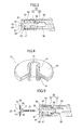
- FIG. 1 is a front elevation which shows in cross-section a portion of the blind rivet which is fastened by means of the tool for fastening blind rivets in the embodiment of the present invention (referred to below as 'the fastening tool').
- the blind rivet includes a rivet body 10 and a mandrel 20. Moreover, it is assembled with a washer 30.
- Mandrel 20 is inserted in a through-hole 13 of rivet body 20 from the sleeve side end of rivet body 10, and a mandrel head 23 of mandrel 20 is placed so as to be contiguous with the sleeve side end of rivet body 10.
- washer 30 is inserted on the outer circumference of sleeve 11 from the sleeve side end of rivet body 10, and is placed so as to be contiguous with rivet head 12.
- Rivet body 10 includes a cylindrical sleeve 11 and a rivet head 12 which is formed on one end of sleeve 11, and which has a diameter larger than sleeve 11.
- the tip of rivet head 12 is an oblique surface 19, the outer diameter of which decreases in a tapered-fashion. It ends in rivet head side end 14.
- oblique surface 19 is squeezed in from its outer circumference by nose piece 51 of the fastening tool for fastening blind rivets, and the outer diameter and the inner diameter decrease.
- a through-hole 13 extends between the rivet head side end 14 of rivet body 10 and the sleeve side end.
- the inner diameter of through-hole 13 is large enough for shaft 21 of mandrel 20 to be inserted, it is smaller than the outer diameter of head 23 of mandrel 20, and head 23 is stopped when it abuts the sleeve side end.
- the outer diameter of sleeve 11 is smaller than the inner diameter of the mounting holes of the mounted component, and is small enough to pass through the mounting holes.
- Mandrel 20 is provided with a long, a thin shaft 21 and a head 23 on one end of the shaft 21.
- the outer diameter of head 23 is larger than the inner diameter of through-hole 13 of rivet body 10.
- the outer diameter of head 23 is smaller than the inner diameter of the mounting holes of mounted components 41 and 42 and can pass through the mounting holes.
- Shaft 21 has a cylindrical shape and has an outer diameter smaller than the inner diameter of through-hole 13 of rivet body 10; it can be inserted in through-hole 13.
- Shaft 21 is longer than the length of through-hole 13 of rivet body 10, and when the shaft 21 of mandrel 20 is inserted in the through-hole 13 of rivet body 10, the tip of shaft 21 projects from the rivet head side end 14 of rivet body 10.
- the shaft 21 of mandrel 20 includes, from the side of head 23, a columnar portion 24, a locking portion 28, a breaking portion 25, a gripping portion 26 and a tip 27. Contiguous with the head 23 is the columnar portion 24.
- the locking portion 28 is contiguous with columnar portion 24. Spaced circumferential grooves are formed on the circumference of locking portion 28, and between the circumferential grooves are locking ridges.
- breaking portion 25 Contiguous with locking portion 28 is the breaking portion 25 which has an outer diameter which is smaller than that of locking portion 28.
- breaking portion 25 is contained in through-hole 13 of rivet body 10. Breaking portion 25 is the portion which breaks when the shaft 21 of mandrel 20 is pulled by the fastening tool, and a certain pull strength is exceeded.
- the gripping portion 26 is contiguous to breaking portion 25 and has a diameter larger than that of breaking portion 25. Multiple locking grooves are formed at gripping portion 26 so that when it is gripped by jaws 54, it does not slip.
- the end of the tip portion 27 of shaft 21 narrows so as to be easily inserted in the fastening tool for fastening blind rivets.
- Washer 30 is not an essential part of the present invention and may be omitted. Washer 30 will now be explained. Washer 30 is a disc-shaped component, and at a central portion in the axial direction, a center hole 31 opens which has a circular cross-section.
- center hole 31 is slightly larger than the outer diameter of head 23 of mandrel 20 and is slightly larger than the outer diameter of sleeve 11, and is smaller than the outer diameter of the rivet head; and in the blind rivet in which the mandrel 20 and rivet body 10 are assembled, washer 30 can be inserted on the outer circumference of sleeve 11 from the side of head 23 of mandrel 20.
- FIG. 2 is an oblique view which shows the entirety of one example of the fastening tool 45 used in the present invention.
- Fastening tool 45 uses compressed air as the drive source.
- Fastening tool 45 is provided with a tool housing 46; a handle 47 which is held by the operator; an air pressure generating device 49 for generating compressed air; a receptacle 48 for collecting the broken mandrels; and a nose 50.
- a trigger lever is attached to handle 47 for operating the fastening tool for fastening blind rivets.
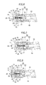
- Figure 3 is an enlarged cross-sectional diagram of the nose 50 of the tip of fastening tool.
- Figure 3 shows part of nose 50 in the starting position before mounting the blind rivet.
- a hollow nose 50 is placed at the tip of fastening tool 45 for receiving the blind rivets.
- Nose 50 is comprised of a hollow nose housing 52 and a nose piece 51 which is integrally connected with the front end portion of nose housing 52.
- Nose housing 52 is cylindrical.
- Nose piece 51 is cylindrical, and at its end, it has an aperture 59 for inserting mandrel 20 of the blind rivets.
- the direction of the tip of nose piece 51 (towards the left in Figure 3 ) is called the forward direction
- the direction of the nose housing 52 (towards the right in Figure 3 ) is called the back direction
- the left side of Figure 3 is called the tip portion
- the right side is called the back end portion.
- a floating piece 60 is placed on the inside of the forward portion of nose piece 51.
- Figure 4 is a cutaway oblique view of a portion of floating piece 60.
- Floating piece 60 is a component which is unique to the present invention.
- Floating piece 60 is provided with a cylindrical first cylindrical portion 61, a flange 63 which extends outward in the radial direction from the back end of first cylindrical portion 61 and a second cylindrical portion 62 which extends from flange 63 in a direction opposite to the first cylindrical portion 61.
- the outer diameter of the first cylindrical portion 61 is slightly smaller than the inner diameter of aperture 59 of nose piece 51 and can be inserted in aperture 59.
- a through-hole 64 is formed which passes through first cylindrical portion 61, second cylindrical portion 62 and flange 63.
- the inner diameter of through-hole 64 is slightly larger than the outer diameter of the shaft of mandrel 20 and can receive the shaft of mandrel 20.
- the outer diameter of flange 63 is slightly smaller than the inner diameter of the cylindrical portion of nose piece 51 and can be received in nose piece 51.
- the back end of the second cylindrical portion 62 is an oblique surface, and although it is preferable to have this abut the oblique surface of the tip of jaw 54, a planar surface may be used instead of an oblique surface.
- a floating piece spring 57 comprised of a coil spring is placed between the outer circumference of flange 63 of floating piece 60 and the front end of nose housing 52, which pushes floating piece 60 forward. In this way, one surface of flange 63 of floating piece 60 abuts the inner surface of the end portion of nose piece 51.
- one surface of flange 63 abuts the inner surface of the end portion of nose piece 51, and the first cylindrical portion 61 is positioned in aperture 59 of nose piece 51, and the second cylindrical portion 62 extends in the axial direction inside nose piece 51 and abuts the tip surface of jaws 54.
- Floating piece 60 can slide in the axial direction inside nose piece 51.
- a tubular jaw guide 53 is contained on the inside of nose piece 51 which abuts one surface of flange 63 of floating piece 60 and can slide in the axial direction relative to nose piece 51.
- Jaws 54 are contained in jaw guide 53 so as to slide in the axial direction relative to jaw guide 53. Jaws 54 are placed so that their tip abuts the back end portion of the second cylindrical portion 62 and are formed with a narrow, pointed configuration towards floating piece 60. Jaws 54 are divided into 2 - 4 parts in the circumferential direction within jaw guide 53, and are assembled within jaw guide 53 to form a tubular structure. Each jaw is combined to forms a space for receiving the mandrel 20 of the blind rivet inside the assembled tubular structure.
- Jaw guide 53 matches jaws 54 and is formed so as to have tapered cavities which have an inner diameter which decreases towards the front (towards the left in Figure 3 ). Jaws 54, which are assembled so as to form a tubular structure with a narrow tip, are received in these tapered cavities so as to be slidable in the axial direction. Accordingly, when jaw guide 53 is forward in the axial direction relative to jaws 54 (the left-hand side of Figure 3 ), it is possible to enlarge the diameter of the space inside the tubular structure formed by the multiple jaws 54; in this way, the mandrel 20 of the blind rivet can be easily received and held.
- jaws 54 are in the open state.
- a hollow tubular jaw pusher 56 is placed inside the jaw guide 53 and the pulling head 55 at the back of jaws 54, which pushes jaws 54 forward.
- a jaw pusher spring 58 comprised of a coil spring is placed between the back end of jaw pusher 56 and the inside of the forward portion of pulling head 55 in order for jaw pusher 56 to push jaws 54 forward.
- Jaw pusher spring 58 is normally biased to push forward, and jaws 54 are pushed to the forward side. In this way, jaws 54 are normally pressed towards floating piece 60 in nose piece 51; and the outer surface of jaws 54, which has a narrow-tipped configuration, is made to abut the tapered inner surface of the interior of jaw guide 53.
- the tip of jaw pusher 56 has an oblique surface and abuts the oblique surface of the back end of jaws 54.
- the oblique surface of the back end portion of the second cylindrical portion 62 and the oblique surface of the tip of jaw pusher 56 work together to push jaws 54 to the outside and widen them; and the diameter inside the space inside the tubular structure formed by the multiple jaws is increased.
- jaw guides 53 When jaw guides 53 are on the forward side in the axial direction relative to jaws 54, the diameter of the space inside the tubular structure formed by the multiple jaws 54 increases, and the mandrel 20 of the blind rivet is easily received. Conversely, when jaw guides 53 are on the back side in the axial direction relative to jaws 54, the diameter of the space inside the tubular structure formed by the multiple jaws 54 decreases, and the mandrel 20 of the blind rivet which is received and held in the space is normally held by the elasticity of the jaw pusher spring 58.
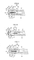
- Figure 5 is a cross-sectional diagram which shows the appearance of the starting position, with the blind rivet set in the mounting holes 43 and 44 of mounted components 41 and 42, before it is set in the fastening tool.
- the left-hand side of Figure 5 is the blind side, and the operation for attaching the blind rivet is done from the right-hand operation side.
- Figure 6 is a cross-sectional diagram showing the step in which mandrel 20 of the blind rivet is inserted.
- the mandrel 20 of the blind rivet passes through a through-hole 64 of floating piece 60 which is in the aperture 59 of nose piece 51; and is inserted between jaws 54, which are open.
- the inserted mandrel 20 is maintained in through-hole 64 of floating piece 60 by means of suctioning by air pressure.
- Figure 7 is a cross-sectional diagram showing the step in which the fastening of the blind rivet at the fastening tool is commenced.
- jaw guide 53 and pulling head 55 move integrally in the backwards direction.
- Floating piece 60 is kept in the starting position by being pressed by floating piece spring 57.
- jaw guide 53 moves in the backwards direction, the outer circumference of jaws 54 are pressed by jaw guide 53 and close, gripping the shaft 21 of mandrel 20.
- Figure 8 is a cross-sectional diagram which shows an intermediate step in fastening a blind rivet at the fastening tool.
- the oblique surface 19 which is near to the tip of rivet head 12 of rivet body 10 is held by nose piece 51, and the gripping portion 26 of mandrel 20 is gripped by jaws 54 and pulled in the backward direction.
- the head 23 of mandrel 20 collapses the sleeve side end portion of sleeve 11 of rivet body 10, forming enlarged diameter portion 18.
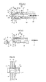
- Figure 9 is a cross-sectional diagram showing a step in which the fastening operation has advanced further, and the gripping portion 26 of mandrel 20 has again been pulled out. While nose piece 51 pushes further on the oblique surface 19 of rivet head 12 from the outer circumference, the outer circumference of rivet head 12 is deformed so that its outer diameter decreases. The inner circumference of through-hole 13 of the inside of rivet head 12 is then deformed so that its inner diameter decreases, and it engages in locking portion 28 of mandrel 20.
- Figure 10 is a cross-sectional diagram which shows the step in which jaws 54 grip the gripping portion 26 of mandrel 20 and pull further, breaking mandrel 20.
- the blind rivet is fastened to mounted components 41 and 42, mandrel 20 is broken at breaking portion 25, and mandrel 20 (from the breaking portion 25 to the head 23 side) remains at the fastened part.
- Floating piece 60 is pushed forward by the pushing force of floating piece spring 57, and the end surface of the first cylindrical portion 61 of floating piece 60 abuts the rivet head side end 14 of rivet body 10.
- the shaft 21 of mandrel 20 (from the breaking portion 25 to the tip portion side) remains gripped in jaws 54 and moves towards the back, exiting at the back through through-hole 64 of floating piece 60.
- Figure 11 is a cross-sectional diagram showing the return step.
- mandrel 20 is broken, when the trigger is off, jaw guide 53 and pulling head 55 move integrally to the front (towards the left in the diagram).
- the shaft 21 of mandrel 20 is gripped by jaws 54 from the breaking portion 25 to the tip portion side and moves with the jaws.
- Figure 12 is a cross-sectional diagram which shows a further return step.
- the force needed to push out rivet head 12 of rivet body 10 is greater than the force of jaw pusher spring 58 which pushes on jaws 54.
- floating piece 60 does not push out rivet head 12, and even though jaw guide 53 moves forward, floating piece 60 does not move, and the second cylindrical portion 62 enters into and is contained in jaw guide 53.
- the end surface of the second cylindrical portion 62 then pushes on jaws 54 and is made to move to the back relative to jaw guide 53, opening jaws 54.
- shaft 21 of mandrel 20 is released from the breaking portion 25 to the tip side, and being suctioned by air, goes towards to receptacle 48.
- Figure 13 is a cross-sectional diagram which shows the appearance when the device is returned to the starting position.
- the end surface of jaw guide 53 abuts flange 63 of floating piece 60, and by means of the high return force of jaw guide 53, floating piece 60 pushes on rivet head side end 14 of rivet body 10, and the fastened blind rivet is pushed out from nose piece 51.
- the mounted components 41 and 42 and the blind rivet are shown falling away, but if mounted components 41 and 42 are fastened, the blind rivet is pushed out while withdrawing the fastening tool.
- Jaws 54 are then pushed back by the end surface of the second cylindrical portion 62 of floating piece 60, and are open. In this way, the device returns to the starting position and the fastening operation is completed. Because jaws 54 are open in the starting position, it is possible to carry out the next blind rivet fastening operation in the starting position.
- the floating piece 60 carries out an opening and closing action of jaws 54, and an action which ejects the deformed rivet head 12 from aperture 59 of nose piece 51.
- the second cylindrical portion 62 pushes jaws 54 towards the back, and jaws 54 open. Also, the first cylindrical portion 61 of floating piece 60 is pushed by jaw guide 53, and pushes out rivet head 12 of rivet body 10 of the fastened blind rivet from aperture 59 of nose piece 51.
- Figure 14 is a front elevation with a portion of the rivet body 10 pushed out from nose piece 51 shown in cross-section.
- Mounted components 41 and 42 are fastened between the enlarged diameter portion 18 of rivet body 10 and washer 30.
- Mandrel 20 (from the breaking portion 25 to the head 23) remains on the fastened part.
- the diameter of the sleeve side end portion of rivet body 10 is enlarged by means of the head 23 of mandrel 20, and because the inner circumference of rivet head 12 of rivet body 10 which has been squeezed in by nose piece 51 engages with the locking portion 28 of mandrel 20, a secure fastening is possible.
- a tool for fastening rivets has a floating piece 60 inside the front end of a nose piece 51. In the starting position, part of floating piece 60 is positioned in aperture 59, and by means of another part of floating piece 60 pushing jaws 54 to the back, jaws 54 open, and it is possible to receive mandrel 20 in jaws 54.
Landscapes
- Engineering & Computer Science (AREA)
- Mechanical Engineering (AREA)
- Insertion Pins And Rivets (AREA)
Abstract
Description
- The present invention pertains to a tool for fastening blind rivets and, in particular, to a fastening tool for fastening blind rivets by deforming part of a rivet body by expanding the diameter thereof and by deforming the rivet head by squeezing the rivet head in.
- Blind rivets which are made from a hollow metal rivet body comprised of a sleeve and a rivet head at one end of a sleeve and a metal mandrel, the shaft of which extends through the through-hole of a rivet body, are well known. Blind rivets have the advantage that several mounted components can be joined by an operation on one side only.
- When fastening mounted components with blind rivets, a tool for fastening blind rivets is used. The tool for fastening blind rivets is provided with a hollow nose housing for housing a blind rivet; a nose piece which is placed at the front end of the nose housing and which has an aperture for inserting the mandrel of the blind rivet; a jaw guide which has an inner circumferential surface which is formed so that the inner diameter thereof decreases towards the front end, and which is placed so as to be moveable forward and back in the nose housing and is contiguous with the back of the nose piece; jaws which have an outer circumferential surface which contacts slidably with the inner circumferential surface of the jaw guide, and which are placed within the jaw guide so as to grip the mandrel of the blind rivet; and a jaw pusher which pushes the jaws forward and which is placed inside the nose housing and is contiguous with the back of the jaws.
- When fastening a blind rivet to a mounted component using a blind rivet fastening tool, the mandrel of the blind rivet is inserted into the aperture of the nose piece of the fastening tool. It is attached in this state, with the rivet body projecting from the nose piece. In this state, the fastening tool is positioned so that the rivet body is inserted into the mounting hole of the mounted component. Next, the fastening tool is put into operation and pulls the mandrel hard enough to break it, and the blind rivet is fastened to the mounted component by deforming the sleeve of the rivet body by expanding the diameter thereof. The broken mandrels are ejected to the back of the fastening tool and collected in a receptacle. Following this, the jaw guide returns to its starting position for attaching the next blind rivet.
- There are many types of blind rivets. Blind rivets are known which fasten by pulling out the mandrel, and after expanding the diameter of one end of the sleeve of the rivet body, the rivet head is squeezed in from the outer circumference by the nose piece of the fastening tool, and the inner circumference of the rivet head engages with the shaft of the mandrel. The fastening tool for fastening this sort of blind rivet cannot increase the outer diameter of the rivet head, because the rivet head is squeezed in by means of the nose piece. For this reason, this is often used with a washer in combination. Also, because the rivet head is gripped in the aperture of the nose piece after fastening, a mechanism for pushing it out of the nose piece is necessary.
- Patent Document 1 discloses a two-component snap fastener tool which is comprised of a tubular collar and a pin component having an enlarged projecting head and a long, thin shaft, and a method of fastening with this snap fastener tool. In the two-component snap fastener of Patent Document 1, the long, thin shaft of the pin component extends through the aperture of the work piece, and the collar is swaged into a retaining groove of the pin component. The shaft of the pin component shears off at a breaking neck portion groove and is fastened. The tool has a jaw portion which engages in a tensioning groove of the pin, inside a tubular collet assembly which is supported so as to be capable of sliding in an anvil housing.
- Patent Document 1 discloses that a collar release component of the tool releases the collar which has been made by a swaging step. However, when the two-component snap fastener is set in the tool, it is necessary to open the jaw portion of the tool so that it grips the tensioning groove of the pin.
- Patent Document 2 discloses a tool for swage-setting a fastener with a two-component structure which is comprised of a pin which passes through the concentric holes of a two-sheeted plate and a sleeve which fits together with the outside of the pin. This tool attaches an outside anvil body which engages with the guard portion of the sleeve of the fastener to a gun body which has a mechanism for gripping and pulling the pin of the fastener. The anvil at the tip of the anvil body has a center hole and carries out the swaging step.
- Patent Document 2 discloses that the pin component is ejected from a center aperture by means of an ejector component which is moveable within the housing. However, when the fastener is set on the tool, the chuck of the tool is made to contact a cap of the back surface, and it is necessary to open the chuck to do the setting.
- In Patent Documents 1 and 2, part of the rivet body is deformed by enlarging the diameter thereof, and the rivet is fastened by deforming the rivet head by squeezing it in. Because the rivet head is squeezed in by the nose piece, it has a mechanism for kicking out the rivet head from the nose piece after fastening.
- In existing tools for fastening blind rivets, a jaw guide is placed in the tip of the inside of a nose piece, and jaws are placed on an inner circumference which narrows towards the front end of the jaw guide. The jaws of the fastening tool are closed in the starting position because the jaws are pushed forward. For this reason, it is necessary to set the rivets by opening the jaws of the tool for fastening blind rivets.
- If the jaws are open at the starting position, setting the rivets in such a fashion is possible and convenient. For this reason, a tool for fastening blind rivets is sought in which the jaws are open at the starting position.
-
- Patent Document 1: Published, Unexamined Patent Application
S 61-144415 - Patent Document 2: Published, Examined Patent Application
S 53-23552 - Accordingly, the object of the present invention is to offer a tool for fastening blind rivets in which the jaws are open at the starting position, and by a return step after the blind rivet is fastened, the blind rivet is pushed out, and the tool returns to its starting position.
- In order to achieve this object, a floating piece which is a single component is given a mechanism for opening and closing the jaws, and a mechanism for ejecting the rivet heads which are deformed after fastening from the nose piece; this floating piece is placed in the inside tip portion of the nose piece and is made to be moveable in the axial direction. By means of pushing the jaws to the back with the tip of the floating piece, a mechanism which opens the jaws in the starting position is made possible.
- A first aspect of the present invention is a tool for fastening blind rivets comprising:
- a hollow nose housing for receiving the mandrel of the blind rivet comprising of a rivet body and a mandrel;
- a nose piece placed at the tip of the nose housing and which has an aperture;
- a floating piece contiguous with the inside of the tip portion of the nose piece, placed so as to be moveable forward and back inside the nose piece, and which has a through-hole for inserting the mandrel and;
- a jaw guide contiguous with the back of the floating piece, placed so as to be moveable within the nose piece and the nose housing, and which has an inner circumferential surface formed so that the inner diameter thereof decreases towards the front end;
- jaws placed inside the jaw guide so that it grips the mandrel which is inserted into the nose piece from the aperture, and which have an outer circumferential surface which slidably contacts the inner circumferential surface of the jaw guide;
- a pulling head connected integrally with the jaw guide and which pulls the jaw guide back relative to the aperture;
- a pulling head which is integrally connected to the jaw guide, and which pulls the jaw guide back relative to the aperture; and
- a jaw pusher placed inside the nose housing, contiguous with the back of the jaws, and which pushes the jaw forward.
- The jaw guide is moved backwards relative to the aperture, and thus the inner diameter of the jaws is narrowed, the mandrel in the jaws is gripped.
- Further the jaw guide and jaw are moved backwards while the mandrel is in a gripped state, and thus the diameter of a portion of the sleeve of the rivet body is enlarged, the rivet head of the rivet body is squeezed, the mandrel is broken, and mounted components are fastened with blind rivets.
- In this way, the tool for fastening rivets can keep the jaws open in the starting position by means of a floating piece which is movable in the axial direction and can eject the rivet head from the nose piece after fastening. This results in an easier fastening operation.
- The floating piece is symmetrical around a center axis, comprising:
- a cylindrical first cylindrical portion;
- a flange extending to the outside in the radial direction from the back end of the first cylindrical portion, and
- a cylindrical second cylindrical portion which extends from the flange to the side opposite the first cylindrical portion. It is desirable to have a through-hole extending from the tip of the first cylindrical portion to the back end portion of the second cylindrical portion.
- In this way, the first cylindrical portion ejects the rivet body after fastening, and the flange abuts the inside tip of the nose piece; the second cylindrical portion pushes the jaws to the back, opening them, and the mandrel goes through the through-hole thus enabling each part to complete its respective function.
- In the start position, the mandrel can be inserted into the nose piece.
- In the starting position of the tool for the fastening of blind rivets,
the first cylindrical portion of the floating piece is placed in the aperture of the nose piece, and
by means of the floating piece spring which is placed between the outer circumferential portion of the flange and the tip of the nose housing, the flange is pushed forward and abuts the inside of the tip of the nose piece.
It is preferable that the back end of the second cylindrical potion abuts the front end of the jaws, and by pushing the jaws backward, the jaws are kept in an open state. - In this way, in the start position, the mandrel can be inserted into the nosepiece.
- In the fastening step, when the rivet head of the rivet body is pulled into the aperture of the nose piece, the first cylindrical portion of the floating piece is pushed into the interior of the nose piece from a position inside the aperture;
during the return step after completion of the fastening operation, it is preferable that the jaw guide pushes the flange of the floating piece forward, and the first cylindrical portion of the floating piece pushes out the rivet head of the rivet body in the aperture to the front; the first cylindrical portion enters into the interior of the aperture, and the tool returns to the starting position. - In this way, the floating piece can push out the rivet head of the rivet body when the tool returns to the starting position.
- A second aspect of the present invention is a floating piece used in a tool for fastening blind rivets provided with a hollow nose housing; a nose piece placed at the front end of the nose housing and which has an aperture; a jaw guide with an inner circumferential surface formed so that the inner diameter thereof decreases towards the front end; jaws with an outer circumferential surface which slidably contacts the inner circumferential surface of the jaw guide; a pulling head which pulls the jaw guide to the back; and a jaw pusher which pushes the jaws forward; and
wherein the floating piece is contiguous with the inside of the tip of the nose piece, and is placed so as to be moveable forward and back in the nose piece,
wherein the floating piece is symmetrical around a center axis and comprises: - a cylindrical first cylindrical portion;
- a flange which extends outward in the radial direction from the back end of the first cylindrical portion; and
- a second cylindrical portion which extends from the flange to the side opposite of the first cylindrical portion; and wherein a through-hole is formed which extends from the tip of the first cylindrical portion to the back end of the second cylindrical portion.
- In this way, it is possible to obtain a component which can be used in a tool for fastening blind rivets and which carries out two functions: the function of maintaining the jaws open in the starting position, and the function of ejecting the rivet heads from the nose piece after fastening.
- It is preferable to form the back end of the second cylindrical portion as an oblique surface which abuts the oblique surface of the tip of the jaws.
- In this way, the floating piece can push and widen the jaws outward in a smooth fashion.
- With the present invention, it is possible to obtain a tool for fastening blind rivets in which the jaws are open at the starting position, and during the return step after the fastening of the blind rivet, the blind rivet is pushed out, and the tool returns to its starting position.
-
- [
Figure 1 ] is a front elevation showing part of a blind rivet in cross-section, before fastening with the tool for fastening blind rivets in the embodiment of the present invention. - [
Figure 2 ] is a front elevation of the tool for fastening blind rivets in an embodiment of the present invention. - [
Figure 3 ] is an enlarged cross-section of the nose portion of the tool for fastening blind rivets. - [
Figure 4 ] is a cutaway oblique view of portion of the floating piece in the nose ofFigure 3 . - [
Figure 5 ] is a cross-sectional diagram which shows the appearance before the blind rivet is set in the fastening tool by the fastening tool ofFigure 3 . - [
Figure 6 ] is a cross-sectional diagram which shows the appearance when the blind rivet is set in the fastening tool by the fastening tool ofFigure 3 . - [
Figure 7 ] is a cross-sectional diagram which shows the beginning step in fastening the blind rivet. - [
Figure 8 ] is a cross-sectional diagram which shows the intermediate step in fastening the blind rivet. - [
Figure 9 ] is a cross-sectional diagram which shows a further step in the fastening operation for the blind rivet. - [
Figure 10 ] is a cross-sectional diagram which shows the stage in which the mandrel is broken. - [
Figure 11 ] is a cross-sectional diagram which shows the return step after fastening the blind rivet. - [
Figure 12 ] is a cross-sectional diagram which shows a further step in the return after fastening the blind rivet. - [
Figure 13 ] is a cross-sectional diagram which shows the appearance when the fastening tool has returned to the starting position. - [
Figure 14 ] is a front elevation which shows part of the fastened portion after fastening the blind rivet, in cross-section. - Next, embodiments of the present invention will be explained with reference to the drawings. Before explaining the fastening tool in the embodiments of the present invention, the blind rivet which is fastened will be explained.
-
Figure 1 is a front elevation which shows in cross-section a portion of the blind rivet which is fastened by means of the tool for fastening blind rivets in the embodiment of the present invention (referred to below as 'the fastening tool'). The blind rivet includes arivet body 10 and amandrel 20. Moreover, it is assembled with awasher 30.Mandrel 20 is inserted in a through-hole 13 ofrivet body 20 from the sleeve side end ofrivet body 10, and amandrel head 23 ofmandrel 20 is placed so as to be contiguous with the sleeve side end ofrivet body 10. Moreover,washer 30 is inserted on the outer circumference ofsleeve 11 from the sleeve side end ofrivet body 10, and is placed so as to be contiguous withrivet head 12. - First, rivet
body 10 will be explained.Rivet body 10 includes acylindrical sleeve 11 and arivet head 12 which is formed on one end ofsleeve 11, and which has a diameter larger thansleeve 11. The tip ofrivet head 12 is anoblique surface 19, the outer diameter of which decreases in a tapered-fashion. It ends in rivethead side end 14. When the blind rivet is fastened,oblique surface 19 is squeezed in from its outer circumference bynose piece 51 of the fastening tool for fastening blind rivets, and the outer diameter and the inner diameter decrease. - A through-
hole 13 extends between the rivethead side end 14 ofrivet body 10 and the sleeve side end. Although the inner diameter of through-hole 13 is large enough forshaft 21 ofmandrel 20 to be inserted, it is smaller than the outer diameter ofhead 23 ofmandrel 20, andhead 23 is stopped when it abuts the sleeve side end. - The outer diameter of
sleeve 11 is smaller than the inner diameter of the mounting holes of the mounted component, and is small enough to pass through the mounting holes. - Next,
mandrel 20 will be explained.Mandrel 20 is provided with a long, athin shaft 21 and ahead 23 on one end of theshaft 21. The outer diameter ofhead 23 is larger than the inner diameter of through-hole 13 ofrivet body 10. The outer diameter ofhead 23 is smaller than the inner diameter of the mounting holes of mountedcomponents Shaft 21 has a cylindrical shape and has an outer diameter smaller than the inner diameter of through-hole 13 ofrivet body 10; it can be inserted in through-hole 13.Shaft 21 is longer than the length of through-hole 13 ofrivet body 10, and when theshaft 21 ofmandrel 20 is inserted in the through-hole 13 ofrivet body 10, the tip ofshaft 21 projects from the rivethead side end 14 ofrivet body 10. - The
shaft 21 ofmandrel 20 includes, from the side ofhead 23, acolumnar portion 24, a lockingportion 28, a breakingportion 25, a grippingportion 26 and atip 27. Contiguous with thehead 23 is thecolumnar portion 24. - The locking
portion 28 is contiguous withcolumnar portion 24. Spaced circumferential grooves are formed on the circumference of lockingportion 28, and between the circumferential grooves are locking ridges. When the blind rivet is fastened, part ofrivet head 12 is squeezed in from the outer circumference by thenose piece 51 of the fastening tool for fastening blind rivets so the inner diameter becomes smaller, and the locking ridges engage in the inner circumference of through-hole 13, the diameter of which has become smaller, and a strong crimping force is produced, so that mountedcomponents - Contiguous with locking
portion 28 is the breakingportion 25 which has an outer diameter which is smaller than that of lockingportion 28. When the blind rivet is in an assembled state, breakingportion 25 is contained in through-hole 13 ofrivet body 10. Breakingportion 25 is the portion which breaks when theshaft 21 ofmandrel 20 is pulled by the fastening tool, and a certain pull strength is exceeded. - The gripping
portion 26 is contiguous to breakingportion 25 and has a diameter larger than that of breakingportion 25. Multiple locking grooves are formed at grippingportion 26 so that when it is gripped byjaws 54, it does not slip. The end of thetip portion 27 ofshaft 21 narrows so as to be easily inserted in the fastening tool for fastening blind rivets. - There are many cases in which a blind rivet is used in combination with a
washer 30 so that the rivet corresponds to the large mounting holes of the mounted components.Washer 30 is not an essential part of the present invention and may be omitted.Washer 30 will now be explained.Washer 30 is a disc-shaped component, and at a central portion in the axial direction, acenter hole 31 opens which has a circular cross-section. The inner diameter ofcenter hole 31 is slightly larger than the outer diameter ofhead 23 ofmandrel 20 and is slightly larger than the outer diameter ofsleeve 11, and is smaller than the outer diameter of the rivet head; and in the blind rivet in which themandrel 20 and rivetbody 10 are assembled,washer 30 can be inserted on the outer circumference ofsleeve 11 from the side ofhead 23 ofmandrel 20. - Next, the fastening tool according to an embodiment of the present invention will be explained.
Figure 2 is an oblique view which shows the entirety of one example of thefastening tool 45 used in the present invention.Fastening tool 45 uses compressed air as the drive source.Fastening tool 45 is provided with atool housing 46; ahandle 47 which is held by the operator; an airpressure generating device 49 for generating compressed air; areceptacle 48 for collecting the broken mandrels; and anose 50. A trigger lever is attached to handle 47 for operating the fastening tool for fastening blind rivets. - In the embodiment of the present invention, although an example is shown which is driven by compressed air, if
jaws 54 whichgrip mandrel 20 can be pulled to the back ofnose 50 in a strong manner, hydraulics, an electric motor, or other drive means can be used. There are various positions and configurations for thetool housing 46, airpressure generating device 49 and thereceptacle 48. The present invention pertains to a portion of thenose 50, and the entire structure of the fastening tool is not limited to what is shown inFigure 2 . Because the entire structure of the fastening tool is well known, it will not be described here in detail. -
Figure 3 is an enlarged cross-sectional diagram of thenose 50 of the tip of fastening tool.Figure 3 shows part ofnose 50 in the starting position before mounting the blind rivet. Ahollow nose 50 is placed at the tip offastening tool 45 for receiving the blind rivets.Nose 50 is comprised of ahollow nose housing 52 and anose piece 51 which is integrally connected with the front end portion ofnose housing 52.Nose housing 52 is cylindrical.Nose piece 51 is cylindrical, and at its end, it has anaperture 59 for insertingmandrel 20 of the blind rivets. - In this Specification, the direction of the tip of nose piece 51 (towards the left in
Figure 3 ) is called the forward direction, and the direction of the nose housing 52 (towards the right inFigure 3 ) is called the back direction. Also, for each structural component, the left side ofFigure 3 is called the tip portion, and the right side is called the back end portion. - A floating
piece 60 is placed on the inside of the forward portion ofnose piece 51.Figure 4 is a cutaway oblique view of a portion of floatingpiece 60. Floatingpiece 60 is a component which is unique to the present invention. Floatingpiece 60 is provided with a cylindrical firstcylindrical portion 61, aflange 63 which extends outward in the radial direction from the back end of firstcylindrical portion 61 and a secondcylindrical portion 62 which extends fromflange 63 in a direction opposite to the firstcylindrical portion 61. The outer diameter of the firstcylindrical portion 61 is slightly smaller than the inner diameter ofaperture 59 ofnose piece 51 and can be inserted inaperture 59. A through-hole 64 is formed which passes through firstcylindrical portion 61, secondcylindrical portion 62 andflange 63. The inner diameter of through-hole 64 is slightly larger than the outer diameter of the shaft ofmandrel 20 and can receive the shaft ofmandrel 20. The outer diameter offlange 63 is slightly smaller than the inner diameter of the cylindrical portion ofnose piece 51 and can be received innose piece 51. - In
Figure 4 , the back end of the secondcylindrical portion 62 is an oblique surface, and although it is preferable to have this abut the oblique surface of the tip ofjaw 54, a planar surface may be used instead of an oblique surface. - A floating
piece spring 57 comprised of a coil spring is placed between the outer circumference offlange 63 of floatingpiece 60 and the front end ofnose housing 52, which pushes floatingpiece 60 forward. In this way, one surface offlange 63 of floatingpiece 60 abuts the inner surface of the end portion ofnose piece 51. - In the starting position for
fastening tool 45, one surface offlange 63 abuts the inner surface of the end portion ofnose piece 51, and the firstcylindrical portion 61 is positioned inaperture 59 ofnose piece 51, and the secondcylindrical portion 62 extends in the axial direction insidenose piece 51 and abuts the tip surface ofjaws 54. Floatingpiece 60 can slide in the axial direction insidenose piece 51. - A
tubular jaw guide 53 is contained on the inside ofnose piece 51 which abuts one surface offlange 63 of floatingpiece 60 and can slide in the axial direction relative tonose piece 51. -
Jaws 54 are contained injaw guide 53 so as to slide in the axial direction relative tojaw guide 53.Jaws 54 are placed so that their tip abuts the back end portion of the secondcylindrical portion 62 and are formed with a narrow, pointed configuration towards floatingpiece 60.Jaws 54 are divided into 2 - 4 parts in the circumferential direction withinjaw guide 53, and are assembled withinjaw guide 53 to form a tubular structure. Each jaw is combined to forms a space for receiving themandrel 20 of the blind rivet inside the assembled tubular structure. - Jaw guide 53
matches jaws 54 and is formed so as to have tapered cavities which have an inner diameter which decreases towards the front (towards the left inFigure 3 ).Jaws 54, which are assembled so as to form a tubular structure with a narrow tip, are received in these tapered cavities so as to be slidable in the axial direction. Accordingly, when jaw guide 53 is forward in the axial direction relative to jaws 54 (the left-hand side ofFigure 3 ), it is possible to enlarge the diameter of the space inside the tubular structure formed by themultiple jaws 54; in this way, themandrel 20 of the blind rivet can be easily received and held. Conversely, when jaw guide 53 is towards the back in the axial direction relative to jaws 54 (right-hand side ofFigure 3 ), the diameter of the space inside the tubular structure formed by themultiple jaws 54 is decreased; in this way, themandrel 20 of the blind rivet which was received in the space is held and maintained. - In the starting position, because the tip of
jaws 54 is pushed towards the back by means of the back end portion of the secondcylindrical portion 62 of floatingpiece 60,jaws 54 are in the open state. - A
tubular pulling head 55 is connected integrally at the back ofjaw guide 53 by means of a screw connection. Although pulling head 55 (and jaw guide 53) can slide in the axial direction withintool housing 46, it cannot rotate around the axis. A tubular drive shaft is connected at the back end of pullinghead 55. - A hollow
tubular jaw pusher 56 is placed inside thejaw guide 53 and the pullinghead 55 at the back ofjaws 54, which pushesjaws 54 forward. Ajaw pusher spring 58 comprised of a coil spring is placed between the back end ofjaw pusher 56 and the inside of the forward portion of pullinghead 55 in order forjaw pusher 56 to pushjaws 54 forward.Jaw pusher spring 58 is normally biased to push forward, andjaws 54 are pushed to the forward side. In this way,jaws 54 are normally pressed towards floatingpiece 60 innose piece 51; and the outer surface ofjaws 54, which has a narrow-tipped configuration, is made to abut the tapered inner surface of the interior ofjaw guide 53. The tip ofjaw pusher 56 has an oblique surface and abuts the oblique surface of the back end ofjaws 54. The oblique surface of the back end portion of the secondcylindrical portion 62 and the oblique surface of the tip ofjaw pusher 56 work together to pushjaws 54 to the outside and widen them; and the diameter inside the space inside the tubular structure formed by the multiple jaws is increased. - When jaw guides 53 are on the forward side in the axial direction relative to
jaws 54, the diameter of the space inside the tubular structure formed by themultiple jaws 54 increases, and themandrel 20 of the blind rivet is easily received. Conversely, when jaw guides 53 are on the back side in the axial direction relative tojaws 54, the diameter of the space inside the tubular structure formed by themultiple jaws 54 decreases, and themandrel 20 of the blind rivet which is received and held in the space is normally held by the elasticity of thejaw pusher spring 58. - The fastening operation for the mounted
components Figures 2 and3 will now be explained, with reference toFigures 5-13 . -
Figure 5 is a cross-sectional diagram which shows the appearance of the starting position, with the blind rivet set in the mountingholes components Figure 5 is the blind side, and the operation for attaching the blind rivet is done from the right-hand operation side. - In the starting position shown in
Figure 5 , floatingpiece 60 abuts the inside of the end portion ofnose piece 51, andjaw guide 53 is in front ofnose housing 52, andjaws 54 are pushed to the back by means of the secondcylindrical portion 62 of floatingpiece 60. For this reason,jaws 54 are open, and because the inner diameter ofjaws 54 increases, it is possible to insertmandrel 20 of the blind rivet at the starting position. -
Figure 6 is a cross-sectional diagram showing the step in which mandrel 20 of the blind rivet is inserted. InFigure 6 , themandrel 20 of the blind rivet passes through a through-hole 64 of floatingpiece 60 which is in theaperture 59 ofnose piece 51; and is inserted betweenjaws 54, which are open. The insertedmandrel 20 is maintained in through-hole 64 of floatingpiece 60 by means of suctioning by air pressure. -
Nose piece 51 is constructed so that only mandrel 20 is received in through-hole 64 of floatingpiece 60, therivet head 12 ofrivet body 10 being stopped and held bynose piece 51. -
Figure 7 is a cross-sectional diagram showing the step in which the fastening of the blind rivet at the fastening tool is commenced. When the trigger is on,jaw guide 53 and pullinghead 55 move integrally in the backwards direction. Floatingpiece 60 is kept in the starting position by being pressed by floatingpiece spring 57. When jaw guide 53 moves in the backwards direction, the outer circumference ofjaws 54 are pressed byjaw guide 53 and close, gripping theshaft 21 ofmandrel 20. -
Figure 8 is a cross-sectional diagram which shows an intermediate step in fastening a blind rivet at the fastening tool. As shown inFigure 8 , when jaw guide 53 moves to the back, theoblique surface 19 which is near to the tip ofrivet head 12 ofrivet body 10 is held bynose piece 51, and the grippingportion 26 ofmandrel 20 is gripped byjaws 54 and pulled in the backward direction. Thehead 23 ofmandrel 20 collapses the sleeve side end portion ofsleeve 11 ofrivet body 10, formingenlarged diameter portion 18.Nose piece 51 pushes theoblique surface 19 ofrivet head 12 from the outer circumference, deformingrivet head 12 so that the outer diameter of its outer circumference decreases, and rivethead 12 enters into theaperture 59 ofnose piece 51.Rivet head 12 then pushes the end surface of the firstcylindrical portion 61 of floatingpiece 60, and this force overcomes the pushing force of floatingpiece spring 57, and the surface offlange 63 of floatingpiece 60 is made to separate from the surface ofnose piece 51. -
Figure 9 is a cross-sectional diagram showing a step in which the fastening operation has advanced further, and the grippingportion 26 ofmandrel 20 has again been pulled out. Whilenose piece 51 pushes further on theoblique surface 19 ofrivet head 12 from the outer circumference, the outer circumference ofrivet head 12 is deformed so that its outer diameter decreases. The inner circumference of through-hole 13 of the inside ofrivet head 12 is then deformed so that its inner diameter decreases, and it engages in lockingportion 28 ofmandrel 20. - If the surface around
aperture 59 of the tip ofnose piece 51 abuts the surface ofwasher 30,rivet head 12 cannot be pulled further intonose piece 51. The blind rivet clamps mountedcomponents enlarged diameter portion 18, which has an enlarged diameter, andwasher 30. By doing so, the blind rivet fastens mountedcomponents cylindrical portion 61 of floatingpiece 60 is then pushed fromaperture 59 intonose piece 51 byrivet head 12. -
Figure 10 is a cross-sectional diagram which shows the step in whichjaws 54 grip the grippingportion 26 ofmandrel 20 and pull further, breakingmandrel 20. The blind rivet is fastened to mountedcomponents mandrel 20 is broken at breakingportion 25, and mandrel 20 (from the breakingportion 25 to thehead 23 side) remains at the fastened part. Floatingpiece 60 is pushed forward by the pushing force of floatingpiece spring 57, and the end surface of the firstcylindrical portion 61 of floatingpiece 60 abuts the rivethead side end 14 ofrivet body 10. Theshaft 21 of mandrel 20 (from the breakingportion 25 to the tip portion side) remains gripped injaws 54 and moves towards the back, exiting at the back through through-hole 64 of floatingpiece 60. -
Figure 11 is a cross-sectional diagram showing the return step. InFigure 11 , becausemandrel 20 is broken, when the trigger is off,jaw guide 53 and pullinghead 55 move integrally to the front (towards the left in the diagram). Theshaft 21 ofmandrel 20 is gripped byjaws 54 from the breakingportion 25 to the tip portion side and moves with the jaws. -
Figure 12 is a cross-sectional diagram which shows a further return step. InFigure 12 , although floatingpiece 60 abuts the rivethead side end 14 ofrivet body 10, the force needed to push outrivet head 12 ofrivet body 10 is greater than the force ofjaw pusher spring 58 which pushes onjaws 54. As a result, floatingpiece 60 does not push outrivet head 12, and even though jaw guide 53 moves forward, floatingpiece 60 does not move, and the secondcylindrical portion 62 enters into and is contained injaw guide 53. The end surface of the secondcylindrical portion 62 then pushes onjaws 54 and is made to move to the back relative tojaw guide 53, openingjaws 54. By means of openingjaws 54,shaft 21 ofmandrel 20 is released from the breakingportion 25 to the tip side, and being suctioned by air, goes towards toreceptacle 48. -
Figure 13 is a cross-sectional diagram which shows the appearance when the device is returned to the starting position. InFigure 13 , the end surface ofjaw guide 53 abutsflange 63 of floatingpiece 60, and by means of the high return force ofjaw guide 53, floatingpiece 60 pushes on rivethead side end 14 ofrivet body 10, and the fastened blind rivet is pushed out fromnose piece 51. InFigure 13 , the mountedcomponents components -
Jaws 54 are then pushed back by the end surface of the secondcylindrical portion 62 of floatingpiece 60, and are open. In this way, the device returns to the starting position and the fastening operation is completed. Becausejaws 54 are open in the starting position, it is possible to carry out the next blind rivet fastening operation in the starting position. - The floating
piece 60 according to the embodiments of the present invention carries out an opening and closing action ofjaws 54, and an action which ejects thedeformed rivet head 12 fromaperture 59 ofnose piece 51. - Namely, in the starting position, the second
cylindrical portion 62 wins out over the force which pushesjaws 54 forward by means ofjaw pusher spring 58, pushingjaws 54 back, andjaws 54 open injaw guide 53. Following this,jaws 54 close andgrip mandrel 20 by means ofjaw guide 53 being pulled towards the back. - After the blind rivet has been fastened and the device returns to the starting position, the second
cylindrical portion 62pushes jaws 54 towards the back, andjaws 54 open. Also, the firstcylindrical portion 61 of floatingpiece 60 is pushed byjaw guide 53, and pushes outrivet head 12 ofrivet body 10 of the fastened blind rivet fromaperture 59 ofnose piece 51. -
Figure 14 is a front elevation with a portion of therivet body 10 pushed out fromnose piece 51 shown in cross-section.Mounted components enlarged diameter portion 18 ofrivet body 10 andwasher 30. - Mandrel 20 (from the breaking
portion 25 to the head 23) remains on the fastened part. The diameter of the sleeve side end portion ofrivet body 10 is enlarged by means of thehead 23 ofmandrel 20, and because the inner circumference ofrivet head 12 ofrivet body 10 which has been squeezed in bynose piece 51 engages with the lockingportion 28 ofmandrel 20, a secure fastening is possible. - According to the embodiments of the present invention, a tool for fastening rivets has a floating
piece 60 inside the front end of anose piece 51. In the starting position, part of floatingpiece 60 is positioned inaperture 59, and by means of another part of floatingpiece 60 pushingjaws 54 to the back,jaws 54 open, and it is possible to receivemandrel 20 injaws 54. - Also, in the return step to the starting position after completion of fastening, the other part of floating
piece 60 again opensjaws 54, and the part of floatingpiece 60 ejects rivethead 12 ofrivet body 10 fromaperture 59 ofnose piece 51; and the part of floatingpiece 60 enters intoaperture 59, and the tool returns to the starting position. - In this way, the floating piece carries out the action of opening and closing the jaws, and the action of ejecting the fastened rivet head from the nose piece, with one component.
- Because the jaws are open in the starting position, it is possible to set the rivet in the starting position.
-
- 10
- rivet body
- 11
- sleeve
- 12
- rivet head
- 13
- through-hole
- 14
- rivet head side end
- 18
- expanded diameter portion
- 19
- oblique surface
- 20
- mandrel
- 21
- shaft
- 23
- head
- 24
- columnar portion
- 25
- breaking portion
- 26
- gripping portion
- 27
- tip
- 28
- locking portion
- 30
- washer
- 31
- center hole
- 41
- mounted component
- 42
- mounted component
- 43
- mounting hole
- 44
- mounting hole
- 45
- fastening tool
- 46
- tool housing
- 47
- handle
- 48
- receptacle
- 49
- air pressure generating tool
- 50
- nose
- 51
- nose piece
- 52
- nose housing
- 53
- jaw guide
- 54
- jaws
- 55
- pulling head
- 56
- jaw pusher
- 57
- floating piece spring
- 58
- jaw pusher spring
- 59
- aperture
- 60
- floating piece
- 61
- first cylindrical portion
- 62
- second cylindrical portion
- 63
- flange
- 64
- through-hole
Claims (6)
- A tool for fastening blind rivets comprising:a hollow nose housing for receiving a mandrel of a blind rivet comprising a rivet body and a mandrel;a nose piece placed at the tip of the nose housing and which has an aperture;a floating piece contiguous with the inside of the tip of the nose piece, placed so as to be moveable forward and back within the nose piece, and which has a through-hole for inserting the mandrel;a jaw guide contiguous with the back of the floating piece, placed so as to be moveable forward and back within the nose piece and the nose housing, and which has an inner circumferential surface formed so that its inner diameter decreases towards the front end;jaws placed inside the jaw guide so that it grips the mandrel inserted into the nose piece from the aperture, and which have an outer circumferential surface which slidably contacts the inner circumferential surface of the jaw guide;a pulling head integrally connected to the jaw guide, and which pulls the jaw guide back relative to the aperture; anda jaw pusher placed in the nose housing, contiguous with the back of the jaws, and which pushes the jaws forward;wherein when the jaw guide is moved backwards relative to the aperture, and thus the inner diameter of the jaws is narrowed, the mandrel in the jaws is gripped,further the jaw guide and jaw are moved backwards while the mandrel is in a gripped state, and thus the diameter of a portion of the sleeve of the rivet body is enlarged, the rivet head of the rivet body is squeezed, the mandrel is broken, and mounted components are fastened with blind rivets.
- A tool for fastening blind rivets as set forth in Claim 1, wherein the floating piece is symmetrical around a center axis, comprising:a cylindrical first cylindrical portion;a flange extending outward in the radial direction from the back end of the first cylindrical portion; anda cylindrical second cylindrical portion which extends from the flange to the side opposite the first cylindrical portion; andwherein a through-hole is formed extending from the tip of the first cylindrical portion to the back end of the second cylindrical portion.
- A tool for fastening blind rivets as set forth in Claim 2, wherein, during the starting position for the tool for fastening blind rivets,
the first cylindrical portion of the floating piece is placed in the aperture of the nose piece,
by means of a floating piece spring placed between the outer circumferential portion of the flange and the tip of the nose housing, the flange is pushed forward and abuts the inside of the tip of the nose piece; and
the back end of the second cylindrical portion abuts the front end of the jaws, and pushing the jaws backwards, keeps the jaws in an open state. - A tool for fastening blind rivets as set forth in Claim 3, wherein, during the fastening step,
when the rivet head of the rivet body is pulled into the aperture of the nose piece, the first cylindrical portion of the floating piece is pushed into the interior of the nose piece from the position within the aperture; and
during the return step after the fastening operation is completed, the jaw guide pushes the flange of the floating piece forward, and the first cylindrical portion of the floating piece ejects the rivet head of the rivet body in the aperture to the front; and the first cylindrical portion enters the aperture, and the tool returns to the starting position. - A floating piece for use in a tool for fastening blind rivets provided with a hollow nose housing; a nose piece placed at the front end of the nose housing and which has an aperture; a jaw guide with an inner circumferential surface formed so that the inner diameter thereof decreases towards the front; jaws with an outer circumferential surface which slidably contacts the inner circumferential surface of the jaw guide; a pulling head which pulls the jaw guide to the back; and a jaw pusher which pushes the jaws forward;
wherein the floating piece is contiguous with the inside of the tip of a nose piece, and is placed so as to be moveable forwards and back in the nose piece,
wherein the floating piece is symmetrical around a center axis and comprises:a cylindrical first cylindrical portion;a flange which extends outward in the radial direction from the back end of the first cylindrical portion; anda second cylindrical portion which extends from the flange to the side opposite of the first cylindrical portion; andwherein a through-hole is formed which extends from the tip of the first cylindrical portion to the back end of the second cylindrical portion. - A floating piece as set forth in Claim 5, wherein the back end of the second cylindrical portion is formed with an oblique surface which abuts the oblique surface of the tip of the jaws.
Applications Claiming Priority (2)
| Application Number | Priority Date | Filing Date | Title |
|---|---|---|---|
| JP2011268837A JP5874967B2 (en) | 2011-12-08 | 2011-12-08 | Blind rivet fastening tool |
| PCT/JP2012/081458 WO2013084913A1 (en) | 2011-12-08 | 2012-12-05 | Blind rivet fastening tool |
Publications (3)
| Publication Number | Publication Date |
|---|---|
| EP2789412A1 true EP2789412A1 (en) | 2014-10-15 |
| EP2789412A4 EP2789412A4 (en) | 2015-12-09 |
| EP2789412B1 EP2789412B1 (en) | 2019-05-15 |
Family
ID=48574271
Family Applications (1)
| Application Number | Title | Priority Date | Filing Date |
|---|---|---|---|
| EP12856453.1A Active EP2789412B1 (en) | 2011-12-08 | 2012-12-05 | Blind rivet fastening tool |
Country Status (7)
| Country | Link |
|---|---|
| US (1) | US9889495B2 (en) |
| EP (1) | EP2789412B1 (en) |
| JP (1) | JP5874967B2 (en) |
| CN (1) | CN103998157B (en) |
| BR (1) | BR112014013686A2 (en) |
| TW (1) | TWI572425B (en) |
| WO (1) | WO2013084913A1 (en) |
Families Citing this family (16)
| Publication number | Priority date | Publication date | Assignee | Title |
|---|---|---|---|---|
| JP2018194009A (en) * | 2014-10-31 | 2018-12-06 | ポップリベット・ファスナー株式会社 | Fastening structure and fastening method |
| CN108246888A (en) * | 2018-02-12 | 2018-07-06 | 珠海格力精密模具有限公司 | Die assembly and mold |
| CN207915402U (en) | 2018-02-13 | 2018-09-28 | 米沃奇电动工具公司 | Nose clip group for rivet setting tool |
| US11697148B1 (en) | 2019-02-08 | 2023-07-11 | Mark Spilker | Hydraulic fastener tool |
| US11292050B1 (en) * | 2019-02-08 | 2022-04-05 | Mark Spilker | Hydraulic fastener tool |
| GB2584142B (en) * | 2019-05-23 | 2023-07-26 | Avdel Uk Ltd | Fastener placement tool |
| JP1657643S (en) * | 2019-09-20 | 2020-04-20 | ||
| JP1661062S (en) * | 2019-09-20 | 2020-06-01 | ||
| TWD211392S (en) * | 2020-01-21 | 2021-05-11 | 新加坡商鴻運科股份有限公司 | Automatic nail supply riveting gun |
| JP7469103B2 (en) | 2020-03-30 | 2024-04-16 | 株式会社マキタ | Fastening Tools |
| CN219632508U (en) | 2020-06-03 | 2023-09-05 | 米沃奇电动工具公司 | Rivet tools and power tools for setting rivets |
| JP7106080B2 (en) * | 2020-09-23 | 2022-07-26 | 株式会社津田工業 | Fastener fastening tool stand and fastener fastening method |
| CN113085207B (en) * | 2021-03-31 | 2022-05-17 | 湖北三江航天万峰科技发展有限公司 | Gun head for hand riveter and using method |
| CN113210562B (en) * | 2021-04-20 | 2022-08-30 | 敏实汽车技术研发有限公司 | Riveter head floating structure suitable for robot riveting |
| WO2024010932A1 (en) | 2022-07-08 | 2024-01-11 | Milwaukee Electric Tool Corporation | Power tool sensing a multi-pole magnet junction |
| JP1759492S (en) * | 2022-11-03 | 2023-12-14 | portable electric screwdriver |
Family Cites Families (30)
| Publication number | Priority date | Publication date | Assignee | Title |
|---|---|---|---|---|
| US3028987A (en) * | 1958-11-07 | 1962-04-10 | Huck Mfg Co | Tool for driving fasteners |
| US3107806A (en) * | 1961-10-05 | 1963-10-22 | Huck Mfg Co | Modified nose assembly |
| US3143903A (en) * | 1961-10-19 | 1964-08-11 | Huck Mfg Co | Crimp lock pull nose assembly |
| US3180017A (en) * | 1962-02-12 | 1965-04-27 | Townsend Company | Lock bolt gun |
| NL125377C (en) * | 1964-06-08 | |||
| US3446509A (en) * | 1966-06-01 | 1969-05-27 | Huck Mfg Co | Chuck jaw |
| US3605478A (en) * | 1968-09-09 | 1971-09-20 | Huck Mfg Co | Integral anvil holder |
| US3774437A (en) * | 1972-03-02 | 1973-11-27 | D Young | Rivet setting apparatus with axially movable collar |
| JPS5323552A (en) | 1976-08-18 | 1978-03-04 | Mitsubishi Electric Corp | Pulse row detection circuit |
| US4248077A (en) * | 1979-11-26 | 1981-02-03 | Gregory Jack T | Jaw for riveter |
| DE3112711C2 (en) * | 1981-03-31 | 1984-11-08 | Gesipa Blindniettechnik Gmbh, 6000 Frankfurt | Pneumatic-hydraulic blind riveting tool |
| US4598571A (en) * | 1984-04-02 | 1986-07-08 | Usm Corporation | Control valve for a mandrel collection system |
| ZA857957B (en) * | 1984-10-24 | 1986-05-28 | Huck Mfg Co | High strenght fastener and method |
| US4867625A (en) | 1985-04-29 | 1989-09-19 | Huck Manufacturing Company | Variable clamp fastener and method |
| GB2174943B (en) * | 1985-05-10 | 1988-08-03 | Avdel Ltd | Breakstem fastener installation tool |
| US4747738A (en) | 1986-10-03 | 1988-05-31 | Avilbank Mfg., Inc. | Captive panel fastener assembly |
| US4836008A (en) * | 1987-12-30 | 1989-06-06 | Emhart Industries, Inc. | Solenoid powered riveting tool |
| US4888974A (en) * | 1989-02-02 | 1989-12-26 | Emhart Industries, Inc. | Control valve for a mandrel collection system |
| JPH0475882A (en) * | 1990-07-13 | 1992-03-10 | Makita Corp | Motor driven tool |
| US5073070A (en) | 1990-09-13 | 1991-12-17 | Avibank Mfg., Inc. | Panel fastener with floating grommet assembly |
| US5399053A (en) | 1993-04-27 | 1995-03-21 | Avibank Mfg., Inc. | Quick action panel fastener assembly including a cup enclosed retainer receiving a bolt therein |
| US5351379A (en) * | 1993-07-20 | 1994-10-04 | Eric Chu | Riveter for efficiently riveting and drafting setting mandrels and scraps |
| US5519926A (en) * | 1994-05-09 | 1996-05-28 | Huck International, Inc. | Nose assembly for hydraulic installation tool |
| AU4055995A (en) * | 1995-02-15 | 1996-08-22 | World Wide Product Development Company Limited | Power operated self-drilling rivet setting tool |
| DE10011340A1 (en) * | 2000-03-10 | 2001-09-20 | Gesipa Blindniettechnik | Pneumatic, hydraulic blind riveting device for inserting blind rivets comprises a pressure space arranged between a resetting piston and a thrust piston which is loaded by a pressure controlled by a control device |
| US6705149B2 (en) * | 2001-05-25 | 2004-03-16 | Huck Patents, Inc. | Universal backup mandrel with retractable sleeve and shock absorbing means |
| US20060090318A1 (en) * | 2004-11-04 | 2006-05-04 | Toosky Rahmatollah F | Self-aligning tool for installation of pull type fastener |
| US8006361B2 (en) * | 2006-02-14 | 2011-08-30 | Physical Systems, Inc. | Installation tool for use with a liner sleeve attachment |
| JP2010260064A (en) * | 2009-04-30 | 2010-11-18 | Nippon Pop Rivets & Fasteners Ltd | Blind rivet fastening device |
| JP5597432B2 (en) * | 2010-04-06 | 2014-10-01 | ポップリベット・ファスナー株式会社 | Electric blind rivet fastening device |
-
2011
- 2011-12-08 JP JP2011268837A patent/JP5874967B2/en active Active
-
2012
- 2012-12-05 WO PCT/JP2012/081458 patent/WO2013084913A1/en not_active Ceased
- 2012-12-05 CN CN201280060688.1A patent/CN103998157B/en active Active
- 2012-12-05 EP EP12856453.1A patent/EP2789412B1/en active Active
- 2012-12-05 BR BR112014013686A patent/BR112014013686A2/en not_active IP Right Cessation
- 2012-12-07 TW TW101146246A patent/TWI572425B/en active
-
2014
- 2014-05-22 US US14/284,725 patent/US9889495B2/en active Active
Also Published As
| Publication number | Publication date |
|---|---|
| CN103998157A (en) | 2014-08-20 |
| EP2789412A4 (en) | 2015-12-09 |
| TW201328797A (en) | 2013-07-16 |
| JP2014223631A (en) | 2014-12-04 |
| US9889495B2 (en) | 2018-02-13 |
| EP2789412B1 (en) | 2019-05-15 |
| US20140250649A1 (en) | 2014-09-11 |
| BR112014013686A2 (en) | 2017-06-13 |
| JP5874967B2 (en) | 2016-03-02 |
| WO2013084913A1 (en) | 2013-06-13 |
| TWI572425B (en) | 2017-03-01 |
| CN103998157B (en) | 2015-12-02 |
Similar Documents
| Publication | Publication Date | Title |
|---|---|---|
| EP2789412B1 (en) | Blind rivet fastening tool | |
| EP2246132A2 (en) | Blind rivet fastening device | |
| US3934325A (en) | Fastening method, apparatus and article | |
| US5136873A (en) | Automatic blind rivet setting device | |
| EP0613409B1 (en) | Automatic feed blind rivet setting tool | |
| US4755087A (en) | Hole saw plug ejector | |
| EP2502686A1 (en) | Blind rivet fastening device | |
| US3906776A (en) | Self-drilling blind riveting tool | |
| JP2006505415A (en) | Split nosepiece for driving connecting screw | |
| KR100980088B1 (en) | Power tools for riveting | |
| US8677588B2 (en) | Rivet setting tool | |
| USRE46857E1 (en) | Electric blind rivet setting device | |
| KR101504442B1 (en) | Rivet-fitting tool | |
| CN113441672B (en) | Automatic hand riveter and operation method thereof | |
| US3423986A (en) | Rivet gun for blind rivets | |
| US3646800A (en) | Mandrel rivet-setting tool | |
| JP2018134656A (en) | Rivet fastening device | |
| US2713439A (en) | Adapter for automatic rivet guns | |
| KR101858208B1 (en) | Rivet gun having punching unit | |
| US2999610A (en) | Rivet setting tool | |
| JP3681615B2 (en) | Riveter | |
| US10022782B1 (en) | Attachment for a rivet setting tool | |
| KR100502293B1 (en) | An air gun for solid type rivet | |
| KR100887542B1 (en) | Power tools for riveting | |
| JPH09155493A (en) | Rivet tightening tool |
Legal Events
| Date | Code | Title | Description |
|---|---|---|---|
| PUAI | Public reference made under article 153(3) epc to a published international application that has entered the european phase |
Free format text: ORIGINAL CODE: 0009012 |
|
| 17P | Request for examination filed |
Effective date: 20140620 |
|
| AK | Designated contracting states |
Kind code of ref document: A1 Designated state(s): AL AT BE BG CH CY CZ DE DK EE ES FI FR GB GR HR HU IE IS IT LI LT LU LV MC MK MT NL NO PL PT RO RS SE SI SK SM TR |
|
| DAX | Request for extension of the european patent (deleted) | ||
| RA4 | Supplementary search report drawn up and despatched (corrected) |
Effective date: 20151110 |
|
| RIC1 | Information provided on ipc code assigned before grant |
Ipc: B21J 15/10 20060101AFI20151104BHEP Ipc: B21J 15/36 20060101ALI20151104BHEP |
|
| RAP1 | Party data changed (applicant data changed or rights of an application transferred) |
Owner name: NEWFREY LLC |
|
| STAA | Information on the status of an ep patent application or granted ep patent |
Free format text: STATUS: EXAMINATION IS IN PROGRESS |
|
| 17Q | First examination report despatched |
Effective date: 20180615 |
|
| GRAP | Despatch of communication of intention to grant a patent |
Free format text: ORIGINAL CODE: EPIDOSNIGR1 |
|
| STAA | Information on the status of an ep patent application or granted ep patent |
Free format text: STATUS: GRANT OF PATENT IS INTENDED |
|
| INTG | Intention to grant announced |
Effective date: 20181127 |
|
| GRAS | Grant fee paid |
Free format text: ORIGINAL CODE: EPIDOSNIGR3 |
|
| GRAA | (expected) grant |
Free format text: ORIGINAL CODE: 0009210 |
|
| STAA | Information on the status of an ep patent application or granted ep patent |
Free format text: STATUS: THE PATENT HAS BEEN GRANTED |
|
| AK | Designated contracting states |
Kind code of ref document: B1 Designated state(s): AL AT BE BG CH CY CZ DE DK EE ES FI FR GB GR HR HU IE IS IT LI LT LU LV MC MK MT NL NO PL PT RO RS SE SI SK SM TR |
|
| REG | Reference to a national code |
Ref country code: CH Ref legal event code: EP Ref country code: GB Ref legal event code: FG4D |
|
| REG | Reference to a national code |
Ref country code: DE Ref legal event code: R096 Ref document number: 602012060241 Country of ref document: DE |
|
| REG | Reference to a national code |
Ref country code: IE Ref legal event code: FG4D |
|
| REG | Reference to a national code |
Ref country code: NL Ref legal event code: MP Effective date: 20190515 |
|
| REG | Reference to a national code |
Ref country code: LT Ref legal event code: MG4D |
|
| PG25 | Lapsed in a contracting state [announced via postgrant information from national office to epo] |
Ref country code: FI Free format text: LAPSE BECAUSE OF FAILURE TO SUBMIT A TRANSLATION OF THE DESCRIPTION OR TO PAY THE FEE WITHIN THE PRESCRIBED TIME-LIMIT Effective date: 20190515 Ref country code: NO Free format text: LAPSE BECAUSE OF FAILURE TO SUBMIT A TRANSLATION OF THE DESCRIPTION OR TO PAY THE FEE WITHIN THE PRESCRIBED TIME-LIMIT Effective date: 20190815 Ref country code: LT Free format text: LAPSE BECAUSE OF FAILURE TO SUBMIT A TRANSLATION OF THE DESCRIPTION OR TO PAY THE FEE WITHIN THE PRESCRIBED TIME-LIMIT Effective date: 20190515 Ref country code: NL Free format text: LAPSE BECAUSE OF FAILURE TO SUBMIT A TRANSLATION OF THE DESCRIPTION OR TO PAY THE FEE WITHIN THE PRESCRIBED TIME-LIMIT Effective date: 20190515 Ref country code: PT Free format text: LAPSE BECAUSE OF FAILURE TO SUBMIT A TRANSLATION OF THE DESCRIPTION OR TO PAY THE FEE WITHIN THE PRESCRIBED TIME-LIMIT Effective date: 20190915 Ref country code: ES Free format text: LAPSE BECAUSE OF FAILURE TO SUBMIT A TRANSLATION OF THE DESCRIPTION OR TO PAY THE FEE WITHIN THE PRESCRIBED TIME-LIMIT Effective date: 20190515 Ref country code: HR Free format text: LAPSE BECAUSE OF FAILURE TO SUBMIT A TRANSLATION OF THE DESCRIPTION OR TO PAY THE FEE WITHIN THE PRESCRIBED TIME-LIMIT Effective date: 20190515 Ref country code: SE Free format text: LAPSE BECAUSE OF FAILURE TO SUBMIT A TRANSLATION OF THE DESCRIPTION OR TO PAY THE FEE WITHIN THE PRESCRIBED TIME-LIMIT Effective date: 20190515 Ref country code: AL Free format text: LAPSE BECAUSE OF FAILURE TO SUBMIT A TRANSLATION OF THE DESCRIPTION OR TO PAY THE FEE WITHIN THE PRESCRIBED TIME-LIMIT Effective date: 20190515 |
|
| PG25 | Lapsed in a contracting state [announced via postgrant information from national office to epo] |
Ref country code: GR Free format text: LAPSE BECAUSE OF FAILURE TO SUBMIT A TRANSLATION OF THE DESCRIPTION OR TO PAY THE FEE WITHIN THE PRESCRIBED TIME-LIMIT Effective date: 20190816 Ref country code: LV Free format text: LAPSE BECAUSE OF FAILURE TO SUBMIT A TRANSLATION OF THE DESCRIPTION OR TO PAY THE FEE WITHIN THE PRESCRIBED TIME-LIMIT Effective date: 20190515 Ref country code: RS Free format text: LAPSE BECAUSE OF FAILURE TO SUBMIT A TRANSLATION OF THE DESCRIPTION OR TO PAY THE FEE WITHIN THE PRESCRIBED TIME-LIMIT Effective date: 20190515 Ref country code: BG Free format text: LAPSE BECAUSE OF FAILURE TO SUBMIT A TRANSLATION OF THE DESCRIPTION OR TO PAY THE FEE WITHIN THE PRESCRIBED TIME-LIMIT Effective date: 20190815 |
|
| REG | Reference to a national code |
Ref country code: AT Ref legal event code: MK05 Ref document number: 1132845 Country of ref document: AT Kind code of ref document: T Effective date: 20190515 |
|
| PG25 | Lapsed in a contracting state [announced via postgrant information from national office to epo] |
Ref country code: SK Free format text: LAPSE BECAUSE OF FAILURE TO SUBMIT A TRANSLATION OF THE DESCRIPTION OR TO PAY THE FEE WITHIN THE PRESCRIBED TIME-LIMIT Effective date: 20190515 Ref country code: RO Free format text: LAPSE BECAUSE OF FAILURE TO SUBMIT A TRANSLATION OF THE DESCRIPTION OR TO PAY THE FEE WITHIN THE PRESCRIBED TIME-LIMIT Effective date: 20190515 Ref country code: CZ Free format text: LAPSE BECAUSE OF FAILURE TO SUBMIT A TRANSLATION OF THE DESCRIPTION OR TO PAY THE FEE WITHIN THE PRESCRIBED TIME-LIMIT Effective date: 20190515 Ref country code: AT Free format text: LAPSE BECAUSE OF FAILURE TO SUBMIT A TRANSLATION OF THE DESCRIPTION OR TO PAY THE FEE WITHIN THE PRESCRIBED TIME-LIMIT Effective date: 20190515 Ref country code: EE Free format text: LAPSE BECAUSE OF FAILURE TO SUBMIT A TRANSLATION OF THE DESCRIPTION OR TO PAY THE FEE WITHIN THE PRESCRIBED TIME-LIMIT Effective date: 20190515 Ref country code: DK Free format text: LAPSE BECAUSE OF FAILURE TO SUBMIT A TRANSLATION OF THE DESCRIPTION OR TO PAY THE FEE WITHIN THE PRESCRIBED TIME-LIMIT Effective date: 20190515 |
|
| REG | Reference to a national code |
Ref country code: DE Ref legal event code: R097 Ref document number: 602012060241 Country of ref document: DE |
|
| PG25 | Lapsed in a contracting state [announced via postgrant information from national office to epo] |
Ref country code: SM Free format text: LAPSE BECAUSE OF FAILURE TO SUBMIT A TRANSLATION OF THE DESCRIPTION OR TO PAY THE FEE WITHIN THE PRESCRIBED TIME-LIMIT Effective date: 20190515 Ref country code: IT Free format text: LAPSE BECAUSE OF FAILURE TO SUBMIT A TRANSLATION OF THE DESCRIPTION OR TO PAY THE FEE WITHIN THE PRESCRIBED TIME-LIMIT Effective date: 20190515 |
|
| PLBE | No opposition filed within time limit |
Free format text: ORIGINAL CODE: 0009261 |
|
| STAA | Information on the status of an ep patent application or granted ep patent |
Free format text: STATUS: NO OPPOSITION FILED WITHIN TIME LIMIT |
|
| PG25 | Lapsed in a contracting state [announced via postgrant information from national office to epo] |
Ref country code: TR Free format text: LAPSE BECAUSE OF FAILURE TO SUBMIT A TRANSLATION OF THE DESCRIPTION OR TO PAY THE FEE WITHIN THE PRESCRIBED TIME-LIMIT Effective date: 20190515 |
|
| 26N | No opposition filed |
Effective date: 20200218 |
|
| PG25 | Lapsed in a contracting state [announced via postgrant information from national office to epo] |
Ref country code: PL Free format text: LAPSE BECAUSE OF FAILURE TO SUBMIT A TRANSLATION OF THE DESCRIPTION OR TO PAY THE FEE WITHIN THE PRESCRIBED TIME-LIMIT Effective date: 20190515 |
|
| PG25 | Lapsed in a contracting state [announced via postgrant information from national office to epo] |
Ref country code: SI Free format text: LAPSE BECAUSE OF FAILURE TO SUBMIT A TRANSLATION OF THE DESCRIPTION OR TO PAY THE FEE WITHIN THE PRESCRIBED TIME-LIMIT Effective date: 20190515 |
|
| REG | Reference to a national code |
Ref country code: CH Ref legal event code: PL |
|
| REG | Reference to a national code |
Ref country code: BE Ref legal event code: MM Effective date: 20191231 |
|
| PG25 | Lapsed in a contracting state [announced via postgrant information from national office to epo] |
Ref country code: MC Free format text: LAPSE BECAUSE OF FAILURE TO SUBMIT A TRANSLATION OF THE DESCRIPTION OR TO PAY THE FEE WITHIN THE PRESCRIBED TIME-LIMIT Effective date: 20190515 |
|
| PG25 | Lapsed in a contracting state [announced via postgrant information from national office to epo] |
Ref country code: IE Free format text: LAPSE BECAUSE OF NON-PAYMENT OF DUE FEES Effective date: 20191205 Ref country code: LU Free format text: LAPSE BECAUSE OF NON-PAYMENT OF DUE FEES Effective date: 20191205 |
|
| PG25 | Lapsed in a contracting state [announced via postgrant information from national office to epo] |
Ref country code: LI Free format text: LAPSE BECAUSE OF NON-PAYMENT OF DUE FEES Effective date: 20191231 Ref country code: BE Free format text: LAPSE BECAUSE OF NON-PAYMENT OF DUE FEES Effective date: 20191231 Ref country code: CH Free format text: LAPSE BECAUSE OF NON-PAYMENT OF DUE FEES Effective date: 20191231 |
|
| PG25 | Lapsed in a contracting state [announced via postgrant information from national office to epo] |
Ref country code: CY Free format text: LAPSE BECAUSE OF FAILURE TO SUBMIT A TRANSLATION OF THE DESCRIPTION OR TO PAY THE FEE WITHIN THE PRESCRIBED TIME-LIMIT Effective date: 20190515 |
|
| PG25 | Lapsed in a contracting state [announced via postgrant information from national office to epo] |
Ref country code: IS Free format text: LAPSE BECAUSE OF FAILURE TO SUBMIT A TRANSLATION OF THE DESCRIPTION OR TO PAY THE FEE WITHIN THE PRESCRIBED TIME-LIMIT Effective date: 20190915 |
|
| PG25 | Lapsed in a contracting state [announced via postgrant information from national office to epo] |
Ref country code: MT Free format text: LAPSE BECAUSE OF FAILURE TO SUBMIT A TRANSLATION OF THE DESCRIPTION OR TO PAY THE FEE WITHIN THE PRESCRIBED TIME-LIMIT Effective date: 20190515 Ref country code: HU Free format text: LAPSE BECAUSE OF FAILURE TO SUBMIT A TRANSLATION OF THE DESCRIPTION OR TO PAY THE FEE WITHIN THE PRESCRIBED TIME-LIMIT; INVALID AB INITIO Effective date: 20121205 |
|
| PG25 | Lapsed in a contracting state [announced via postgrant information from national office to epo] |
Ref country code: MK Free format text: LAPSE BECAUSE OF FAILURE TO SUBMIT A TRANSLATION OF THE DESCRIPTION OR TO PAY THE FEE WITHIN THE PRESCRIBED TIME-LIMIT Effective date: 20190515 |
|
| P01 | Opt-out of the competence of the unified patent court (upc) registered |
Effective date: 20230912 |
|
| PGFP | Annual fee paid to national office [announced via postgrant information from national office to epo] |
Ref country code: GB Payment date: 20251218 Year of fee payment: 14 |
|
| PGFP | Annual fee paid to national office [announced via postgrant information from national office to epo] |
Ref country code: FR Payment date: 20251218 Year of fee payment: 14 |
|
| PGFP | Annual fee paid to national office [announced via postgrant information from national office to epo] |
Ref country code: DE Payment date: 20251222 Year of fee payment: 14 |