EP2788603B1 - Gasturbinenmotor mit veränderlichem gesamtdruckverhältnis - Google Patents
Gasturbinenmotor mit veränderlichem gesamtdruckverhältnis Download PDFInfo
- Publication number
- EP2788603B1 EP2788603B1 EP12787998.9A EP12787998A EP2788603B1 EP 2788603 B1 EP2788603 B1 EP 2788603B1 EP 12787998 A EP12787998 A EP 12787998A EP 2788603 B1 EP2788603 B1 EP 2788603B1
- Authority
- EP
- European Patent Office
- Prior art keywords
- high pressure
- clutch
- air flow
- gas turbine
- pressure compressor
- Prior art date
- Legal status (The legal status is an assumption and is not a legal conclusion. Google has not performed a legal analysis and makes no representation as to the accuracy of the status listed.)
- Active
Links
- 238000000034 method Methods 0.000 claims description 8
- 238000013022 venting Methods 0.000 claims 1
- 230000001141 propulsive effect Effects 0.000 description 4
- 238000012986 modification Methods 0.000 description 3
- 230000004048 modification Effects 0.000 description 3
- 238000010276 construction Methods 0.000 description 2
- 230000009977 dual effect Effects 0.000 description 2
- 239000000446 fuel Substances 0.000 description 2
- 230000003068 static effect Effects 0.000 description 2
- 230000003044 adaptive effect Effects 0.000 description 1
- 230000008878 coupling Effects 0.000 description 1
- 238000010168 coupling process Methods 0.000 description 1
- 238000005859 coupling reaction Methods 0.000 description 1
- 238000005474 detonation Methods 0.000 description 1
- 230000015654 memory Effects 0.000 description 1
Images


Classifications
-
- F—MECHANICAL ENGINEERING; LIGHTING; HEATING; WEAPONS; BLASTING
- F02—COMBUSTION ENGINES; HOT-GAS OR COMBUSTION-PRODUCT ENGINE PLANTS
- F02C—GAS-TURBINE PLANTS; AIR INTAKES FOR JET-PROPULSION PLANTS; CONTROLLING FUEL SUPPLY IN AIR-BREATHING JET-PROPULSION PLANTS
- F02C7/00—Features, components parts, details or accessories, not provided for in, or of interest apart form groups F02C1/00 - F02C6/00; Air intakes for jet-propulsion plants
- F02C7/36—Power transmission arrangements between the different shafts of the gas turbine plant, or between the gas-turbine plant and the power user
-
- F—MECHANICAL ENGINEERING; LIGHTING; HEATING; WEAPONS; BLASTING
- F02—COMBUSTION ENGINES; HOT-GAS OR COMBUSTION-PRODUCT ENGINE PLANTS
- F02C—GAS-TURBINE PLANTS; AIR INTAKES FOR JET-PROPULSION PLANTS; CONTROLLING FUEL SUPPLY IN AIR-BREATHING JET-PROPULSION PLANTS
- F02C3/00—Gas-turbine plants characterised by the use of combustion products as the working fluid
- F02C3/14—Gas-turbine plants characterised by the use of combustion products as the working fluid characterised by the arrangement of the combustion chamber in the plant
- F02C3/145—Gas-turbine plants characterised by the use of combustion products as the working fluid characterised by the arrangement of the combustion chamber in the plant the combustion chamber being in the reverse flow-type
-
- F—MECHANICAL ENGINEERING; LIGHTING; HEATING; WEAPONS; BLASTING
- F02—COMBUSTION ENGINES; HOT-GAS OR COMBUSTION-PRODUCT ENGINE PLANTS
- F02C—GAS-TURBINE PLANTS; AIR INTAKES FOR JET-PROPULSION PLANTS; CONTROLLING FUEL SUPPLY IN AIR-BREATHING JET-PROPULSION PLANTS
- F02C7/00—Features, components parts, details or accessories, not provided for in, or of interest apart form groups F02C1/00 - F02C6/00; Air intakes for jet-propulsion plants
- F02C7/32—Arrangement, mounting, or driving, of auxiliaries
-
- F—MECHANICAL ENGINEERING; LIGHTING; HEATING; WEAPONS; BLASTING
- F02—COMBUSTION ENGINES; HOT-GAS OR COMBUSTION-PRODUCT ENGINE PLANTS
- F02K—JET-PROPULSION PLANTS
- F02K3/00—Plants including a gas turbine driving a compressor or a ducted fan
- F02K3/08—Plants including a gas turbine driving a compressor or a ducted fan with supplementary heating of the working fluid; Control thereof
- F02K3/105—Heating the by-pass flow
-
- F—MECHANICAL ENGINEERING; LIGHTING; HEATING; WEAPONS; BLASTING
- F05—INDEXING SCHEMES RELATING TO ENGINES OR PUMPS IN VARIOUS SUBCLASSES OF CLASSES F01-F04
- F05D—INDEXING SCHEME FOR ASPECTS RELATING TO NON-POSITIVE-DISPLACEMENT MACHINES OR ENGINES, GAS-TURBINES OR JET-PROPULSION PLANTS
- F05D2220/00—Application
- F05D2220/70—Application in combination with
- F05D2220/76—Application in combination with an electrical generator
-
- F—MECHANICAL ENGINEERING; LIGHTING; HEATING; WEAPONS; BLASTING
- F05—INDEXING SCHEMES RELATING TO ENGINES OR PUMPS IN VARIOUS SUBCLASSES OF CLASSES F01-F04
- F05D—INDEXING SCHEME FOR ASPECTS RELATING TO NON-POSITIVE-DISPLACEMENT MACHINES OR ENGINES, GAS-TURBINES OR JET-PROPULSION PLANTS
- F05D2260/00—Function
- F05D2260/40—Transmission of power
- F05D2260/402—Transmission of power through friction drives
- F05D2260/4023—Transmission of power through friction drives through a friction clutch
-
- F—MECHANICAL ENGINEERING; LIGHTING; HEATING; WEAPONS; BLASTING
- F05—INDEXING SCHEMES RELATING TO ENGINES OR PUMPS IN VARIOUS SUBCLASSES OF CLASSES F01-F04
- F05D—INDEXING SCHEME FOR ASPECTS RELATING TO NON-POSITIVE-DISPLACEMENT MACHINES OR ENGINES, GAS-TURBINES OR JET-PROPULSION PLANTS
- F05D2260/00—Function
- F05D2260/96—Preventing, counteracting or reducing vibration or noise
Definitions
- the present disclosure generally relates to gas turbine engines and, more particularly, to apparatus and methods for providing a variable overall pressure ratio in a gas turbine engine.
- Gas turbine engines are commonly used to propel aircraft.
- the efficiency and performance of the gas turbine engine may vary according to the form of the engine and the flight parameters of the aircraft. In general, however, the operating efficiency of conventional gas turbine engines used in aircraft is not optimized throughout the flight envelope. More specifically, the operating efficiency typically includes several components, such as propulsive efficiency and thermal efficiency, that peak at different power settings.
- the overall pressure ratio (OPR) of a gas turbine engine can influence when peak propulsive or thermal efficiency is reached. In most conventional aircraft, OPR is fixed and therefore the efficiency components typically peak at different power settings.
- variable pressure ratio engines have been proposed in an effort to better coordinate peak propulsive and thermal efficiencies.
- United States Patent Application Publication No. 2010/0223903 A1 to Starr published on September 9, 2010 , discloses a variable pressure ratio compressor for a gas turbine engine in which rear stages of the compressor may be selectively engaged to increase the pressure ratio.
- the engine includes an air bypass and a valve controlling access to the bypass. When the rear stages are engaged, the valve is closed so that air flow is directed through the rear stages. Alternatively, when the rear stages are disengaged, the valve is opened to divert air flow around the rear stages.
- the Starr '903 application discloses a clutch for selectively engaging the rear stages that is positioned between the forward and rear compressor stages, which is proximate the combustor. Consequently, the clutch is exposed to temperatures as high as approximately 1000° F (538°C), which necessitates the use of high temperature clutch components, thereby increasing the cost of the compressor. Additionally, only a limited space is available at that location, and therefore the assembly proposed in the Starr '903 application appears impractical.
- a prior art engine, having the features of the preamble of claim 1 is disclosed in GB-2405181 .
- the high pressure spool includes a primary shaft coupled to the high pressure turbine and the primary rotors of the high pressure compressor, and a secondary shaft coupled to the secondary rotors of the high pressure compressor.
- the clutch selectively engages the secondary shaft to the primary shaft, thereby to selectively engage the secondary stage to the primary stage.
- the primary shaft includes an aft end
- the secondary shaft includes an aft end
- the clutch is disposed adjacent the aft ends of the primary and secondary shafts.
- the gas turbine engine further comprises a compressor diffuser configured to fluidly communicate from the high pressure compressor primary stage to the combustor, thereby producing a bypass flow around the high pressure compressor secondary stage.
- the set of secondary rotors comprises at least two secondary rotors.
- the gas turbine engine further comprises a generator directly coupled to the primary shaft.
- the generator is disposed aft of the clutch.
- the gas turbine engine further comprises a controller operatively coupled to the clutch, the controller having a loiter mode in which the clutch is engaged and a takeoff mode in which the clutch is disengaged.
- the gas turbine engine further comprises a fan coupled to the low pressure spool by a fan drive gear system.
- the gas turbine engine further comprises an intermediate pressure spool disposed forward of the high pressure spool, the intermediate pressure spool including an intermediate pressure compressor configured for a rearward air flow, and an intermediate pressure turbine disposed aft of the intermediate pressure compressor and configured for a forward air flow.
- Each of the engines includes a high pressure compressor having at least a primary stage having a set of primary rotors and a secondary stage having a set of secondary rotors.
- a clutch is provided to selectively engage the secondary rotors with the primary rotors.
- engagement of the clutch may be controlled based on the vehicle travel mode. On an aircraft, for example, the clutch may be disengaged during a takeoff mode and engaged during a loiter mode. Under high thrust conditions during takeoff, the clutch may be disengaged to depower the secondary stage of the high pressure compressor, thereby reducing turbine entry temperature ("T3").
- the clutch may be engaged to power the secondary stage of the high pressure compressor, which increases OPR and thermal efficiency, and reduces core size. Accordingly, the OPR of the engine may be adjusted to optimize propulsive and thermal efficiencies during different modes of operation, thereby reducing fuel consumption. It is to be understood that the gas turbine engines described herein are for illustrative purposes only and to present background for some of the various components of a general,turbine engine. Other components of a turbine engine unnecessary for an understanding of the present disclosure are not described.
- the gas turbine engine has an inlet through which air enters the gas turbine engine and an outlet, generally positioned opposite the inlet, through which air exits the gas turbine engine.
- the inlet defines a "front” or “forward” portion of the engine, while the outlet defines an “aft” or “rearward” portion of the engine. Accordingly, when a subject component is described as being “forward” of another reference component or point, the subject component is positioned closer to the inlet of the engine than the reference component or point.
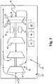
- FIG. 1 a schematic illustration of an aircraft 20 is shown having a gas turbine engine 22, a flight condition sensor 24, a controller 26, and a clutch 28.
- the aircraft 20 may take any variety of forms, including but not limited to helicopters, airplanes, unmanned space vehicles, rotary wing vehicles, and hover crafts. Additionally, the gas turbine engines disclosed herein may be used in other applications that do not involve aircraft, such as, for example, maritime propulsion and other applications known to one of ordinary skill in the art.
- the gas turbine engine 22 includes a first or low pressure spool 30 and a second or high pressure spool 32 disposed aft the low pressure spool 30.
- the low pressure spool 30 includes a low pressure compressor 34 configured for a rearward air flow and a low pressure turbine 36 configured for a forward air flow.
- the high pressure spool 32 includes a high pressure compressor 38 and a high pressure turbine 40, both of which are configured for a forward air flow.
- a combustor 42 is positioned between the high pressure compressor 38 and the high pressure turbine 40. Ducting is provided to direct a rearward flowing air flow 44 into the low pressure compressor 34.
- a reverse flow duct is provided having an inlet located downstream of the low pressure compressor 34 for routing the air flow around the other gas turbine engine components and redirecting the air flow in a forward direction. Forwardly flowing air flow 46 then passes sequentially through the high pressure compressor 38, the combustor 42, the high pressure turbine 40, and the low pressure turbine 36, before being routed to a rearward flowing exhaust air flow 48.
- the high pressure compressor 38 includes a primary stage 50 including a set of primary rotors and a secondary stage 52 including a set of secondary rotors.
- the clutch 28 selectively engages the secondary stage 52 to the primary stage 50 based on a clutch signal provided by the controller 26.
- the controller 26 may be communicatively coupled to the flight condition sensor 24 to receive a flight condition signal. Based on the flight condition signal, the controller 26 may determine whether to send a clutch engage or a clutch disengage signal. For example, when the flight condition signal indicates that the aircraft 20 is in a takeoff mode, the controller 26 may generate a clutch disengage signal, thereby depowering the secondary stage 52 of the high pressure compressor 38.
- the flight condition signal may indicate that the aircraft 20 is in a loiter mode, in which case the controller 26 generates a clutch engage signal to power the secondary stage 52.
- the flight condition signal may include a T3 signal indicating a sensed turbine entry temperature and a power demand signal indicating the amount of power requested from the engine, and the engine 22 is controlled based on these signals.
- An optional high pressure compressor bypass 54 may be provided for directing air around the secondary stage 52 when the secondary stage 52 is depowered.
- the flight condition sensor 24 measures aircraft flight conditions such as speed and altitude, for example, and may output any variety of data whether sensed or calculated.
- the flight condition sensor 24 may sense and output conditions such as static temperature, static pressure, total temperature, and/or total pressure, among others.
- the flight condition sensor 24 may output calculated values such as equivalent airspeed, altitude, and Mach number, to name a few examples. Any number of other sensed conditions or calculated values may also be output.
- the flight condition sensor 24 provides data to the controller 26 and may output values in either analog or digital form.
- the controller 26 is typically positioned in an avionics bay and may be a single component or a collection of operatively coupled components.
- the controller 26 may be comprised of digital circuitry, analog circuitry, or a hybrid combination of both.
- the controller 26 may be programmable, an integrated state machine, or a hybrid combination thereof.
- the controller 26 may include one or more Arithmetic Logic Units (ALUs), Central Processing Units (CPUs), memories, limiters, conditioners, filters, format converters, or the like.
- ALUs Arithmetic Logic Units
- CPUs Central Processing Units
- memories limiters, conditioners, filters, format converters, or the like.
- the controller 26 is programmable and executes algorithms and processes data according to operating logic defined by programming instructions, such as software and firmware.
- operating logic for the controller 26 may be at least partially defined by hardwired logic or other hardware.
- the controller 26 is configured to operate as a Full Authority Digital Engine Control (FADEC); however in other embodiments it may be configured in a different manner.
- the controller may be exclusively dedicated to control of the clutch 28, or may further be used to regulate, control, and/or activate one or more other subsystems or aspects of the aircraft 20 or gas turbine engine 22.
- the gas turbine engine 22 illustrated in FIG. 1 is depicted as a turbojet engine, but may take on other forms in other embodiments, such as, for example, turbofans, turboshafts, and turboprops.
- the gas turbine engine 22 may also be integrated into a high speed propulsion system that may include a ramjet or scramjet.
- the gas turbine engine 22 may be operated as an adaptive or variable cycle engine.
- the gas turbine engine 22 may incorporate combustors such as pulse detonation combustors or wave rotor combustors.
- the rotating turbomachinery such as the compressors and turbines may incorporate active tip clearance control and may have variable geometry.
- FIG. 2 illustrates an alternative embodiment of a gas turbine engine 100 constructed according to the present disclosure.
- the gas turbine engine 100 includes a low pressure spool 102 including a first shaft 104 coupled to a first fan 106 directly, or via a fan drive gear system 108.
- An intermediate pressure turbine 110 is also coupled to the first shaft 104 and is disposed aft of the first fan 106.
- the first fan 106 is configured for a rearward air flow while the intermediate pressure turbine 110 is configured for a forward air flow.
- One or more optional generators 121 may be operatively coupled to the low pressure spool 102 to share power during some portions of the flight envelope.
- the engine 100 may also include an intermediate pressure spool 111 having a second shaft 114.
- a second fan 116 is coupled to the second shaft 114, is disposed aft of the first fan 106, and is configured for a rearward air flow.
- An intermediate pressure compressor 118 is also coupled to the second shaft 114, is disposed aft of the second fan 116, and is configured for a rearward air flow.
- a low pressure turbine 120 is coupled to the second shaft 114, is disposed aft of the intermediate pressure compressor 118 and forward of the intermediate pressure turbine 110, and is configured for a forward air flow.
- the gas turbine engine 100 includes a high pressure spool 122 disposed generally aft of the low pressure spool 102.
- the high pressure spool 122 includes a high pressure turbine 126 disposed aft of the intermediate pressure turbine 110 and configured for a forward air flow, and a high pressure compressor 130 disposed aft of the high pressure turbine 126 and configured for a forward air flow.
- a combustor 128 is disposed between the high pressure compressor 130 and the high pressure turbine 126.
- the combustor 128 is a dual dome combustor with dual diffusers, however other types of combustors may be used without departing from the scope of this disclosure.
- the high pressure compressor 130 includes a primary stage 132, including a set of primary rotors 134, and a secondary stage 136, including a set of secondary rotors 138, wherein the primary stage 132 is disposed aft of the secondary stage 136. While the embodiment illustrated in FIG. 2 shows the primary stage 132 including seven rows of primary rotors 134 and the secondary stage 136 including two rows of secondary rotors 138, it will be appreciated that more or less rows of rotors may be provided in the stages.
- a primary shaft 140 is coupled to the high pressure turbine 126 and the secondary stage 136 of the high pressure compressor 130.
- a secondary shaft 142 is coupled to the secondary stage 136 of the high pressure compressor 130.
- the primary and secondary shafts 140, 142 have respective aft ends 144, 146 disposed aft of the high pressure compressor 130.
- a clutch 148 is provided to selectively engage the secondary stage 136 to the primary stage 132.
- the clutch 148 may include a first set of clutch plates 150 coupled to the aft end 144 of the primary shaft 140 and a second set of clutch plates 152 coupled to the aft end 146 of the secondary shaft 142.
- a clutch actuator 154 is operatively coupled to the clutch plates 150, 152 to mechanically engage or disengage the clutch plates 150, 152.
- the secondary shaft 142 may rotate relative to the primary shaft 140 and the secondary stage 136 is depowered.
- a high pressure compressor diffuser 155 may optionally be provided to bypass air flow around the secondary stage 136 when the secondary stage 136 is depowered. As best shown in FIG. 2 , the high pressure compressor diffuser 155 is located at an intermediate case 156 disposed between the primary and secondary stages 132, 136. The diffuser 155 diverts air flow around the secondary stage 136 to the combustor 128.
- a generator 158 may be operatively coupled to the primary shaft 140.
- the generator 158 may be directly coupled to the primary shaft 140 as shown, without an intervening gear box, so that the generator 158 is directly driven by the primary shaft 140.
- This directly coupled arrangement permits the use of all electric architecture in the aircraft.
- the generator 158 is disposed aft of the clutch 148.
- the generator 158 may be located forward of the clutch 148.
- a controller (not shown), such as controller 26 described above in connection with the embodiment of FIG. 1 , may be operatively coupled to the clutch 148. As noted above, the controller may engage or disengage the clutch based on aircraft flight condition or other sensed or calculated parameters.
- the gas turbine engine 100 include a fan case 160, first and second flow splitters 161, 162, an exhaust duct 164, a compressor case 166, a core engine case 168, a reverse duct 170, and an exhaust pipe 172 for directing air exiting the intermediate pressure turbine 110 into the exhaust duct 164.
- the fan case 160 surrounds the blades of the first and second fans 106, 116 to direct an inlet air flow 180 in a rearward direction.
- the exhaust duct 164 extends from the fan case 160 to the rear of the engine 100.
- the first flow splitter 161 is axially positioned between the second fan 116 and a forward end of the intermediate pressure compressor 118 to separate a low pressure fan flow 181 from the inlet air flow 180.
- the second flow splitter 162 is axially positioned mid-way along the intermediate pressure compressor 118 to divide the inlet air flow 180 into a high pressure fan flow 182 and a core air flow 184.
- the reverse duct 170 reverses the rearward directed core air flow 184 exiting the intermediate pressure compressor 118 to provide a forwardly directed core air flow 186 that travels through the high pressure compressor 130, combustor 128, high pressure turbine 126, and intermediate pressure turbine 110.
- the exhaust pipe 172 directs the core air flow exiting the intermediate pressure turbine 110 into the exhaust duct 164.
- While the exemplary gas turbine engine 100 is shown in FIG. 2 as having three spools, it is contemplated that the engine 100 may employ only two spools or more than three spools without departing from this disclosure.
- An exemplary two spool embodiment may be provided by coupling the first shaft 104 to the second shaft 114 so that the rotate together, however other two (and three) spool configurations may be employed.
- one or more spools may be located to the front of the gas turbine engine 100, while a single high pressure spool may be located to the rear of the engine.
- a fan drive gear system may be provided for higher bypass configurations.
- the gas turbine engines disclosed herein may be used to propel vehicles, such as aircrafts, and the like.
- the use of high pressure compressors having multiple stages that can be engaged or disengaged allows for better management of OPR and T3 during different modes of aircraft operation.
- the secondary stage of the high pressure compressor may be disengaged during takeoff, thereby to reduce T3.
- the secondary stage When the secondary stage is disengaged, it may be permitted to free wheel. Power may be extracted from the free-wheeling secondary stage to drive propulsors, thereby further reducing T3. Some air flow may be bypassed through the high pressure compressor diffuser to reduce losses.
- the secondary stage may be engaged to increase OPR and reduce core size, thereby increasing fuel efficiency.
- the clutch provided to engage and disengage the secondary stage may be advantageously located in a low temperature area with minimal space limitations. Specifically, by using a gas turbine engine with a reverse-flow core, the clutch may be positioned aft of the high pressure compressor and away from the combustor. This location not only has a lower temperature, but does not impose space limitations by requiring the clutch to be disposed between compressor components.
Claims (14)
- Gasturbinenmotor (22), umfassend:eine Niedrigdruckspule (30; 102), umfassend:einen Niedrigdruckkompressor (34), der für einen nach hinten gerichteten Luftstrom ausgestaltet ist (44; 184); undeine Niedrigdruckturbine (36; 120), die sich hinter dem Niedrigdruckkompressor (34) befindet und für einen nach vorn gerichteten Luftstrom ausgestaltet ist (46; 186);eine Hochdruckspule (32; 122), die sich hinter der Niedrigdruckturbine (30; 102) befindet und Folgendes umfasst:dadurch gekennzeichnet, dass der Motor (22) ferner Folgendes umfasst:eine Hochdruckturbine (40; 126), die sich hinter der Niedrigdruckturbine (30; 120) befindet und für einen nach vorn gerichteten Luftstrom ausgestaltet ist (46; 186);eine Brennkammer (32; 128), die sich hinter der Hochdruckturbine (40; 126) befindet; undeinen Hochdruckkompressor (38; 130), der sich hinter der Brennkammer (32; 128) befindet und für einen nach vorn gerichteten Luftstrom ausgestaltet ist (46; 186), wobei der Hochdruckkompressor (38; 130) einen Erstabschnitt (50; 132) umfasst, der eine Reihe erster Rotoren (134) umfasst, sowie einen Zweitabschnitt (52; 136), der eine Reihe zweiter Rotoren (138) umfasst, wobei der Erstabschnitt (50; 132) sich hinter dem Zweitabschnitt (52; 136) befindet;eine Kupplung (28; 148), zum Einkuppeln des ersten und zweiten Abschnitts (50, 52; 132, 136) ausgestaltet, wobei sich die Kupplung (28; 148) hinter dem Hochdruckkompressor (38; 130) befindet.
- Gasturbinenmotor (22) nach Anspruch 1, wobei die Hochdruckspule (32; 122) einen ersten Schaft (140) umfasst, der an die Hochdruckturbine (40; 126) gekoppelt und die ersten Rotoren (134) des Hochdruckkompressors (38; 130) gekoppelt ist, und einen zweiten Schaft (142), der an die zweite Rotoren (138) des Hochdruckkompressors (38; 130) gekoppelt ist.
- Gasturbinenmotor (22) nach Anspruch 2, wobei die Kupplung (28; 148) selektiv den zweiten Schaft (142) in den ersten Schaft (140) einkuppelt, um dadurch selektiv den zweiten Abschnitt (52; 136) in den ersten Abschnitt (50; 132) einzukuppeln.
- Gasturbinenmotor (22) nach Anspruch 3, wobei der erste Schaft (140) ein hinteres Ende (144) umfasst, der zweite Schaft (142) ein hinteres Ende (146) umfasst, und die Kupplung (148) sich neben den hinteren Enden (144, 146) des ersten und zweiten Schafts (140, 142) befindet.
- Gasturbinenmotor (22) nach einem der vorangehenden Ansprüche, ferner einen Kompressordiffusor (155) umfasst, der zur Fließkommunikation vom Hochdruckkompressorerstabschnitt (132) zur Brennkammer (128) ausgestaltet ist, wodurch ein Umgehungsstrom um den Hochdruckkompressorzweitabschnitt (136) erzeugt wird.
- Gasturbinenmotor (22) nach einem der vorangehenden Ansprüche, wobei die Reihe zweiter Rotoren (138) mindestens zwei Zweitrotoren enthält.
- Gasturbinenmotor (22) nach einem der vorangehenden Ansprüche, ferner einen Generator (158) umfassend, der direkt an die Hochdruckspule (122) gekoppelt ist.
- Gasturbinenmotor (22) nach Anspruch 7, wobei sich der Generator (158) hinter der Kupplung (148) befindet.
- Gasturbinenmotor (22) nach einem der vorangehenden Ansprüche, ferner eine Steuerung (26) umfassend, die an die Kupplung (28; 148) betriebsgekoppelt sind, wobei die Steuerung (26) einen Wartemodus hat, bei dem die Kupplung (28; 148) betätigt ist, sowie einen Startmodus hat, in dem die Kupplung (28; 148) gelöst ist.
- Gasturbinenmotor (22) nach einem der vorangehenden Ansprüche, ferner einen Fan (106) umfassend, der durch ein Fanantriebsschaltungsystem an die Niedrigdruckspule (30; 102) gekoppelt ist.
- Gasturbinenmotor (22) nach einem der vorangehenden Ansprüche, ferner eine mittlere Druckspule umfassend, die sich vor der Hochdruckspule (122) befindet, wobei die mittlere Druckspule einen mittleren Druckkompressor (118) umfasst, der für einen nach hinten gerichteten Luftstrom (184) ausgestaltet ist, sowie eine mittlere Druckturbine (110), die sich hinter dem mittleren Druckkompressor (118) befindet und für einen nach vorne gerichteten Luftstrom (186) ausgestaltet ist.
- Verfahren zum Betreiben eines Gasturbinenmotors (22) für ein Flugzeug mit einem Startmodus und einem Wartemodus, wobei das Verfahren Folgendes umfasst:Bereitstellen einer Niedrigdruckspule (30; 102) mit einem Niedrigdruckkompressor (34) und einer Niedrigdruckturbine (36; 120), die sich hinter dem Niedrigdruckkompressor (34) befindet;Bereitstellen einer Hochdruckspule (32; 122), die sich hinter der Niedrigdruckturbine (30; 102) befindet und eine Hochdruckturbine (40; 126) umfasst, die sich hinter der Niedrigdruckturbine (36; 120) befindet, eine Brennkammer (32; 138), die sich hinter der Hochdruckturbine (40; 126) befindet, und einen Hochdruckkompressor (38; 130), der sich hinter einer Brennkammer (32; 128) befindet, wobei der Hochdruckkompressor (38; 130) einen Erstabschnitt (50; 132) umfasst, der eine Reihe erster Rotoren (134) umfasst, sowie einen Zweitabschnitt (52; 136), der eine Reihe zweiter Rotoren (138) umfasst, wobei der Erstabschnitt (50; 132) sich hinter dem Zweitabschnitt (52; 136) befindet;Erzeugen eines axial nach hinten gerichteten Fanluftstroms (44) mit einem Fanantriebsschaltsystem;Aufteilen der Fanluft (44) in einen Niedrigdruckfanluftstrom (181), der nach hinten und in ein Abgasrohr geleitet wird, sowie einen Hauptluftstrom (184), der nach hinten in den Niedrigdruckkompressor (34) geleitet wird;Umleiten des Hauptluftstroms (184) von dem Niedrigdruckkompressor (34) in ein Umkehrstromrohr zur Erzeugung eines axial nach vorn gerichteten Stroms (46; 186) der Hauptluft;Leiten des Vorwärtsstroms (46; 186) der Hauptluft nacheinander durch den Hochdruckkompressor (38; 130), die Brennkammer (32; 128), die Hochdruckturbine (40; 126) und die Niedrigdruckturbine (36; 120) zum Erzeugen von Abgas; undEntlüften des Abgases in das Abgasrohr;dadurch gekennzeichnet, dass das Verfahren ferner Folgendes umfasst:Bereitstellen einer Kupplung, zum selektiven Einkuppeln des ersten und zweiten Abschnitts (50, 52; 132, 136) ausgestaltet, wobei sich die Kupplung hinter dem Hochdruckkompressor (38; 130) befindet;Lösen der Kupplung (28; 148), wenn sich das Flugzeug im Startmodus befindet; sowie Betätigen der Kupplung (28; 148), wenn sich das Flugzeug im Wartemodus befindet.
- Verfahren nach Anspruch 12, ferner das Bereitstellen eines Kompressordiffusors (155) umfassend, der zur Fließkommunikation vom Hochdruckkompressorerstabschnitt (132) zur Brennkammer (128) ausgestaltet ist, wodurch ein Umgehungsstrom um den Hochdruckkompressorzweitabschnitt (136) erzeugt wird, wenn die Kupplung (148) gelöst ist und das Flugzeug sich im Startmodus befindet.
- Verfahren nach Anspruch 12 oder 13, ferner nach dem Aufteilen der Fanluft in den Niedrigdruckfanluftstrom (181) und den Hauptluftstrom (184) das Trennen eines Hochdruckfanluftstroms vom Hauptluftstrom (184) umfassend, wobei der Hochdruckfanluftstrom nach hinten geleitet wird.
Applications Claiming Priority (2)
| Application Number | Priority Date | Filing Date | Title |
|---|---|---|---|
| US13/316,058 US8935912B2 (en) | 2011-12-09 | 2011-12-09 | Gas turbine engine with variable overall pressure ratio |
| PCT/US2012/062659 WO2013085641A1 (en) | 2011-12-09 | 2012-10-31 | Gas turbine engine with variable overall pressure ratio |
Publications (2)
| Publication Number | Publication Date |
|---|---|
| EP2788603A1 EP2788603A1 (de) | 2014-10-15 |
| EP2788603B1 true EP2788603B1 (de) | 2016-04-27 |
Family
ID=47192143
Family Applications (1)
| Application Number | Title | Priority Date | Filing Date |
|---|---|---|---|
| EP12787998.9A Active EP2788603B1 (de) | 2011-12-09 | 2012-10-31 | Gasturbinenmotor mit veränderlichem gesamtdruckverhältnis |
Country Status (5)
| Country | Link |
|---|---|
| US (1) | US8935912B2 (de) |
| EP (1) | EP2788603B1 (de) |
| CN (1) | CN103906910B (de) |
| SG (1) | SG11201402972XA (de) |
| WO (1) | WO2013085641A1 (de) |
Families Citing this family (27)
| Publication number | Priority date | Publication date | Assignee | Title |
|---|---|---|---|---|
| US9222409B2 (en) * | 2012-03-15 | 2015-12-29 | United Technologies Corporation | Aerospace engine with augmenting turbojet |
| US9140212B2 (en) * | 2012-06-25 | 2015-09-22 | United Technologies Corporation | Gas turbine engine with reverse-flow core having a bypass flow splitter |
| US9523329B2 (en) * | 2013-03-15 | 2016-12-20 | United Technologies Corporation | Gas turbine engine with stream diverter |
| US9810145B1 (en) * | 2013-06-11 | 2017-11-07 | Philip C. Bannon | Ducted impeller |
| US10550764B2 (en) * | 2013-12-13 | 2020-02-04 | United Technologies Corporation | Architecture for an axially compact, high performance propulsion system |
| US10100675B2 (en) | 2014-12-09 | 2018-10-16 | United Technologies Corporation | Outer diffuser case for a gas turbine engine |
| US20160169102A1 (en) * | 2014-12-12 | 2016-06-16 | United Technologies Corporation | Reverse core flow gas turbine engine |
| DE102015205516A1 (de) * | 2014-12-22 | 2016-06-23 | Dürr Systems GmbH | Vorrichtung und Verfahren zur thermischen Abgasreinigung |
| US11225913B2 (en) | 2015-02-19 | 2022-01-18 | Raytheon Technologies Corporation | Method of providing turbine engines with different thrust ratings |
| US10794273B2 (en) * | 2015-07-01 | 2020-10-06 | Raytheon Technologies Corporation | Advanced distributed engine architecture-design alternative |
| US11415063B2 (en) * | 2016-09-15 | 2022-08-16 | Pratt & Whitney Canada Corp. | Reverse-flow gas turbine engine |
| US10883424B2 (en) | 2016-07-19 | 2021-01-05 | Pratt & Whitney Canada Corp. | Multi-spool gas turbine engine architecture |
| US10393067B2 (en) * | 2016-08-25 | 2019-08-27 | United Technologies Corporation | Gas turbine engine with cold turbine and multiple core flowpaths |
| US11035293B2 (en) | 2016-09-15 | 2021-06-15 | Pratt & Whitney Canada Corp. | Reverse flow gas turbine engine with offset RGB |
| US10465611B2 (en) | 2016-09-15 | 2019-11-05 | Pratt & Whitney Canada Corp. | Reverse flow multi-spool gas turbine engine with aft-end accessory gearbox drivingly connected to both high pressure spool and low pressure spool |
| US10385774B2 (en) * | 2016-09-19 | 2019-08-20 | United Technologies Corporation | Split compressor turbine engine |
| US10815899B2 (en) | 2016-11-15 | 2020-10-27 | Pratt & Whitney Canada Corp. | Gas turbine engine accessories arrangement |
| US10533559B2 (en) * | 2016-12-20 | 2020-01-14 | Pratt & Whitney Canada Corp. | Reverse flow engine architecture |
| US20180216525A1 (en) * | 2017-01-30 | 2018-08-02 | Pratt & Whitney Canada Corp. | Gas turbine engine architecture with split compressor system |
| US10808624B2 (en) | 2017-02-09 | 2020-10-20 | Pratt & Whitney Canada Corp. | Turbine rotor with low over-speed requirements |
| US11149578B2 (en) * | 2017-02-10 | 2021-10-19 | General Electric Company | Propulsion system for an aircraft |
| US10746188B2 (en) | 2017-03-14 | 2020-08-18 | Pratt & Whitney Canada Corp. | Inter-shaft bearing connected to a compressor boost system |
| US10473028B2 (en) | 2017-07-17 | 2019-11-12 | United Technologies Corporation | Clutched compressor section for gas turbine engine |
| US11231043B2 (en) * | 2018-02-21 | 2022-01-25 | General Electric Company | Gas turbine engine with ultra high pressure compressor |
| CA3051562A1 (en) | 2018-08-08 | 2020-02-08 | Pratt & Whitney Canada Corp. | Multi-engine system and method |
| US10482299B1 (en) | 2018-11-05 | 2019-11-19 | Sammy Kayara | Parent and dependent recycling product codes for finished products |
| US11781506B2 (en) | 2020-06-03 | 2023-10-10 | Rtx Corporation | Splitter and guide vane arrangement for gas turbine engines |
Family Cites Families (12)
| Publication number | Priority date | Publication date | Assignee | Title |
|---|---|---|---|---|
| US2504181A (en) * | 1950-04-18 | Double compound independent rotor | ||
| GB390448A (en) | 1931-10-24 | 1933-04-06 | Milo Ab | Improvements in or relating to gas turbine plants particularly for propulsion of ships |
| US4007892A (en) | 1971-07-15 | 1977-02-15 | Tabor Alga M | Aircraft flight method and apparatus for boosting an aircraft to a very high altitude and thereafter boosting the aircraft to a high rate of forward speed |
| US4222235A (en) | 1977-07-25 | 1980-09-16 | General Electric Company | Variable cycle engine |
| EP0103370A1 (de) * | 1982-08-11 | 1984-03-21 | Rolls-Royce Plc | Gasturbinenmotoren |
| FR2646473B1 (fr) * | 1989-04-26 | 1991-07-05 | Snecma | Moteur a soufflantes contrarotatives tractrices |
| US6134880A (en) * | 1997-12-31 | 2000-10-24 | Concepts Eti, Inc. | Turbine engine with intercooler in bypass air passage |
| FR2858999B1 (fr) * | 2003-08-18 | 2005-11-11 | Snecma Moteurs | Turbomachine pour aeronef a emissions de bruit reduites |
| US20060137355A1 (en) * | 2004-12-27 | 2006-06-29 | Pratt & Whitney Canada Corp. | Fan driven emergency generator |
| US8887485B2 (en) | 2008-10-20 | 2014-11-18 | Rolls-Royce North American Technologies, Inc. | Three spool gas turbine engine having a clutch and compressor bypass |
| WO2010078497A1 (en) * | 2008-12-31 | 2010-07-08 | Rolls-Royce North American Technologies, Inc. | Variable pressure ratio compressor |
| US8176725B2 (en) | 2009-09-09 | 2012-05-15 | United Technologies Corporation | Reversed-flow core for a turbofan with a fan drive gear system |
-
2011
- 2011-12-09 US US13/316,058 patent/US8935912B2/en active Active
-
2012
- 2012-10-31 WO PCT/US2012/062659 patent/WO2013085641A1/en active Application Filing
- 2012-10-31 SG SG11201402972XA patent/SG11201402972XA/en unknown
- 2012-10-31 EP EP12787998.9A patent/EP2788603B1/de active Active
- 2012-10-31 CN CN201280055152.0A patent/CN103906910B/zh active Active
Also Published As
| Publication number | Publication date |
|---|---|
| CN103906910A (zh) | 2014-07-02 |
| EP2788603A1 (de) | 2014-10-15 |
| SG11201402972XA (en) | 2014-07-30 |
| US20130145769A1 (en) | 2013-06-13 |
| CN103906910B (zh) | 2016-06-29 |
| US8935912B2 (en) | 2015-01-20 |
| WO2013085641A1 (en) | 2013-06-13 |
Similar Documents
| Publication | Publication Date | Title |
|---|---|---|
| EP2788603B1 (de) | Gasturbinenmotor mit veränderlichem gesamtdruckverhältnis | |
| US8887485B2 (en) | Three spool gas turbine engine having a clutch and compressor bypass | |
| EP3403933B1 (de) | Hybridelektrisches antriebssystem für ein luftfahrzeug | |
| EP3421369B1 (de) | Antriebssystem für ein flugzeug | |
| EP3428068B1 (de) | Antriebssystem für ein flugzeug | |
| US10953995B2 (en) | Propulsion system for an aircraft | |
| EP2226487B1 (de) | Variable Antriebseinrichtung für Gasturbine | |
| US10738706B2 (en) | Propulsion system for an aircraft | |
| EP3244036B1 (de) | Luftturbinensystem mit doppelnutzung für einen gasturbinenmotor | |
| US10569759B2 (en) | Propulsion system for an aircraft | |
| EP2472081B1 (de) | Gasturbinenmotor mit variablem Zyklus | |
| EP2964931B1 (de) | Fahrzeugrekuperator | |
| US11428171B2 (en) | Electric machine assistance for multi-spool turbomachine operation and control | |
| US20230415902A1 (en) | Aircraft powerplant with boosted gas turbine engine | |
| US20230407795A1 (en) | Shaft power transfer for a multi spool gas turbine engine | |
| EP3845746A1 (de) | Verzahnter mehrkerngasturbinenmotor | |
| EP4310309A1 (de) | Hybrid-elektrisches antriebssystem mit einem koppler zum umschalten zwischen betriebsmodi | |
| CN115075955A (zh) | 涡轮轴发动机离合器构造 |
Legal Events
| Date | Code | Title | Description |
|---|---|---|---|
| PUAI | Public reference made under article 153(3) epc to a published international application that has entered the european phase |
Free format text: ORIGINAL CODE: 0009012 |
|
| 17P | Request for examination filed |
Effective date: 20140627 |
|
| AK | Designated contracting states |
Kind code of ref document: A1 Designated state(s): AL AT BE BG CH CY CZ DE DK EE ES FI FR GB GR HR HU IE IS IT LI LT LU LV MC MK MT NL NO PL PT RO RS SE SI SK SM TR |
|
| DAX | Request for extension of the european patent (deleted) | ||
| GRAP | Despatch of communication of intention to grant a patent |
Free format text: ORIGINAL CODE: EPIDOSNIGR1 |
|
| INTG | Intention to grant announced |
Effective date: 20151028 |
|
| GRAS | Grant fee paid |
Free format text: ORIGINAL CODE: EPIDOSNIGR3 |
|
| GRAA | (expected) grant |
Free format text: ORIGINAL CODE: 0009210 |
|
| AK | Designated contracting states |
Kind code of ref document: B1 Designated state(s): AL AT BE BG CH CY CZ DE DK EE ES FI FR GB GR HR HU IE IS IT LI LT LU LV MC MK MT NL NO PL PT RO RS SE SI SK SM TR |
|
| REG | Reference to a national code |
Ref country code: GB Ref legal event code: FG4D |
|
| REG | Reference to a national code |
Ref country code: CH Ref legal event code: EP |
|
| REG | Reference to a national code |
Ref country code: AT Ref legal event code: REF Ref document number: 795084 Country of ref document: AT Kind code of ref document: T Effective date: 20160515 |
|
| REG | Reference to a national code |
Ref country code: IE Ref legal event code: FG4D |
|
| REG | Reference to a national code |
Ref country code: DE Ref legal event code: R096 Ref document number: 602012017816 Country of ref document: DE |
|
| REG | Reference to a national code |
Ref country code: LT Ref legal event code: MG4D |
|
| REG | Reference to a national code |
Ref country code: NL Ref legal event code: MP Effective date: 20160427 |
|
| REG | Reference to a national code |
Ref country code: AT Ref legal event code: MK05 Ref document number: 795084 Country of ref document: AT Kind code of ref document: T Effective date: 20160427 |
|
| PG25 | Lapsed in a contracting state [announced via postgrant information from national office to epo] |
Ref country code: NL Free format text: LAPSE BECAUSE OF FAILURE TO SUBMIT A TRANSLATION OF THE DESCRIPTION OR TO PAY THE FEE WITHIN THE PRESCRIBED TIME-LIMIT Effective date: 20160427 |
|
| REG | Reference to a national code |
Ref country code: CH Ref legal event code: PCOW Free format text: NEW ADDRESS: 10 FARM SPRINGS RD., FARMINGTON, CT 06032 (US) |
|
| RAP2 | Party data changed (patent owner data changed or rights of a patent transferred) |
Owner name: UNITED TECHNOLOGIES CORPORATION |
|
| PG25 | Lapsed in a contracting state [announced via postgrant information from national office to epo] |
Ref country code: NO Free format text: LAPSE BECAUSE OF FAILURE TO SUBMIT A TRANSLATION OF THE DESCRIPTION OR TO PAY THE FEE WITHIN THE PRESCRIBED TIME-LIMIT Effective date: 20160727 Ref country code: PL Free format text: LAPSE BECAUSE OF FAILURE TO SUBMIT A TRANSLATION OF THE DESCRIPTION OR TO PAY THE FEE WITHIN THE PRESCRIBED TIME-LIMIT Effective date: 20160427 Ref country code: FI Free format text: LAPSE BECAUSE OF FAILURE TO SUBMIT A TRANSLATION OF THE DESCRIPTION OR TO PAY THE FEE WITHIN THE PRESCRIBED TIME-LIMIT Effective date: 20160427 Ref country code: LT Free format text: LAPSE BECAUSE OF FAILURE TO SUBMIT A TRANSLATION OF THE DESCRIPTION OR TO PAY THE FEE WITHIN THE PRESCRIBED TIME-LIMIT Effective date: 20160427 |
|
| PG25 | Lapsed in a contracting state [announced via postgrant information from national office to epo] |
Ref country code: ES Free format text: LAPSE BECAUSE OF FAILURE TO SUBMIT A TRANSLATION OF THE DESCRIPTION OR TO PAY THE FEE WITHIN THE PRESCRIBED TIME-LIMIT Effective date: 20160427 Ref country code: AT Free format text: LAPSE BECAUSE OF FAILURE TO SUBMIT A TRANSLATION OF THE DESCRIPTION OR TO PAY THE FEE WITHIN THE PRESCRIBED TIME-LIMIT Effective date: 20160427 Ref country code: RS Free format text: LAPSE BECAUSE OF FAILURE TO SUBMIT A TRANSLATION OF THE DESCRIPTION OR TO PAY THE FEE WITHIN THE PRESCRIBED TIME-LIMIT Effective date: 20160427 Ref country code: PT Free format text: LAPSE BECAUSE OF FAILURE TO SUBMIT A TRANSLATION OF THE DESCRIPTION OR TO PAY THE FEE WITHIN THE PRESCRIBED TIME-LIMIT Effective date: 20160829 Ref country code: LV Free format text: LAPSE BECAUSE OF FAILURE TO SUBMIT A TRANSLATION OF THE DESCRIPTION OR TO PAY THE FEE WITHIN THE PRESCRIBED TIME-LIMIT Effective date: 20160427 Ref country code: HR Free format text: LAPSE BECAUSE OF FAILURE TO SUBMIT A TRANSLATION OF THE DESCRIPTION OR TO PAY THE FEE WITHIN THE PRESCRIBED TIME-LIMIT Effective date: 20160427 Ref country code: SE Free format text: LAPSE BECAUSE OF FAILURE TO SUBMIT A TRANSLATION OF THE DESCRIPTION OR TO PAY THE FEE WITHIN THE PRESCRIBED TIME-LIMIT Effective date: 20160427 Ref country code: GR Free format text: LAPSE BECAUSE OF FAILURE TO SUBMIT A TRANSLATION OF THE DESCRIPTION OR TO PAY THE FEE WITHIN THE PRESCRIBED TIME-LIMIT Effective date: 20160728 |
|
| PG25 | Lapsed in a contracting state [announced via postgrant information from national office to epo] |
Ref country code: BE Free format text: LAPSE BECAUSE OF FAILURE TO SUBMIT A TRANSLATION OF THE DESCRIPTION OR TO PAY THE FEE WITHIN THE PRESCRIBED TIME-LIMIT Effective date: 20160427 Ref country code: IT Free format text: LAPSE BECAUSE OF FAILURE TO SUBMIT A TRANSLATION OF THE DESCRIPTION OR TO PAY THE FEE WITHIN THE PRESCRIBED TIME-LIMIT Effective date: 20160427 |
|
| REG | Reference to a national code |
Ref country code: DE Ref legal event code: R097 Ref document number: 602012017816 Country of ref document: DE |
|
| PG25 | Lapsed in a contracting state [announced via postgrant information from national office to epo] |
Ref country code: CZ Free format text: LAPSE BECAUSE OF FAILURE TO SUBMIT A TRANSLATION OF THE DESCRIPTION OR TO PAY THE FEE WITHIN THE PRESCRIBED TIME-LIMIT Effective date: 20160427 Ref country code: RO Free format text: LAPSE BECAUSE OF FAILURE TO SUBMIT A TRANSLATION OF THE DESCRIPTION OR TO PAY THE FEE WITHIN THE PRESCRIBED TIME-LIMIT Effective date: 20160427 Ref country code: EE Free format text: LAPSE BECAUSE OF FAILURE TO SUBMIT A TRANSLATION OF THE DESCRIPTION OR TO PAY THE FEE WITHIN THE PRESCRIBED TIME-LIMIT Effective date: 20160427 Ref country code: SK Free format text: LAPSE BECAUSE OF FAILURE TO SUBMIT A TRANSLATION OF THE DESCRIPTION OR TO PAY THE FEE WITHIN THE PRESCRIBED TIME-LIMIT Effective date: 20160427 Ref country code: DK Free format text: LAPSE BECAUSE OF FAILURE TO SUBMIT A TRANSLATION OF THE DESCRIPTION OR TO PAY THE FEE WITHIN THE PRESCRIBED TIME-LIMIT Effective date: 20160427 |
|
| PG25 | Lapsed in a contracting state [announced via postgrant information from national office to epo] |
Ref country code: SM Free format text: LAPSE BECAUSE OF FAILURE TO SUBMIT A TRANSLATION OF THE DESCRIPTION OR TO PAY THE FEE WITHIN THE PRESCRIBED TIME-LIMIT Effective date: 20160427 |
|
| PLBE | No opposition filed within time limit |
Free format text: ORIGINAL CODE: 0009261 |
|
| STAA | Information on the status of an ep patent application or granted ep patent |
Free format text: STATUS: NO OPPOSITION FILED WITHIN TIME LIMIT |
|
| REG | Reference to a national code |
Ref country code: FR Ref legal event code: PLFP Year of fee payment: 5 |
|
| 26N | No opposition filed |
Effective date: 20170130 |
|
| PG25 | Lapsed in a contracting state [announced via postgrant information from national office to epo] |
Ref country code: SI Free format text: LAPSE BECAUSE OF FAILURE TO SUBMIT A TRANSLATION OF THE DESCRIPTION OR TO PAY THE FEE WITHIN THE PRESCRIBED TIME-LIMIT Effective date: 20160427 |
|
| REG | Reference to a national code |
Ref country code: CH Ref legal event code: PL |
|
| REG | Reference to a national code |
Ref country code: DE Ref legal event code: R082 Ref document number: 602012017816 Country of ref document: DE Representative=s name: SCHMITT-NILSON SCHRAUD WAIBEL WOHLFROM PATENTA, DE |
|
| REG | Reference to a national code |
Ref country code: DE Ref legal event code: R082 Ref document number: 602012017816 Country of ref document: DE Representative=s name: SCHMITT-NILSON SCHRAUD WAIBEL WOHLFROM PATENTA, DE Ref country code: DE Ref legal event code: R081 Ref document number: 602012017816 Country of ref document: DE Owner name: UNITED TECHNOLOGIES CORP. (N.D.GES.D. STAATES , US Free format text: FORMER OWNER: UNITED TECHNOLOGIES CORPORATION, HARTFORD, CONN., US |
|
| REG | Reference to a national code |
Ref country code: IE Ref legal event code: MM4A |
|
| PG25 | Lapsed in a contracting state [announced via postgrant information from national office to epo] |
Ref country code: LI Free format text: LAPSE BECAUSE OF NON-PAYMENT OF DUE FEES Effective date: 20161031 Ref country code: CH Free format text: LAPSE BECAUSE OF NON-PAYMENT OF DUE FEES Effective date: 20161031 |
|
| PG25 | Lapsed in a contracting state [announced via postgrant information from national office to epo] |
Ref country code: LU Free format text: LAPSE BECAUSE OF NON-PAYMENT OF DUE FEES Effective date: 20161031 |
|
| REG | Reference to a national code |
Ref country code: FR Ref legal event code: PLFP Year of fee payment: 6 |
|
| PG25 | Lapsed in a contracting state [announced via postgrant information from national office to epo] |
Ref country code: IE Free format text: LAPSE BECAUSE OF NON-PAYMENT OF DUE FEES Effective date: 20161031 |
|
| PG25 | Lapsed in a contracting state [announced via postgrant information from national office to epo] |
Ref country code: HU Free format text: LAPSE BECAUSE OF FAILURE TO SUBMIT A TRANSLATION OF THE DESCRIPTION OR TO PAY THE FEE WITHIN THE PRESCRIBED TIME-LIMIT; INVALID AB INITIO Effective date: 20121031 |
|
| PG25 | Lapsed in a contracting state [announced via postgrant information from national office to epo] |
Ref country code: MC Free format text: LAPSE BECAUSE OF FAILURE TO SUBMIT A TRANSLATION OF THE DESCRIPTION OR TO PAY THE FEE WITHIN THE PRESCRIBED TIME-LIMIT Effective date: 20160427 Ref country code: MT Free format text: LAPSE BECAUSE OF NON-PAYMENT OF DUE FEES Effective date: 20161031 Ref country code: CY Free format text: LAPSE BECAUSE OF FAILURE TO SUBMIT A TRANSLATION OF THE DESCRIPTION OR TO PAY THE FEE WITHIN THE PRESCRIBED TIME-LIMIT Effective date: 20160427 Ref country code: IS Free format text: LAPSE BECAUSE OF FAILURE TO SUBMIT A TRANSLATION OF THE DESCRIPTION OR TO PAY THE FEE WITHIN THE PRESCRIBED TIME-LIMIT Effective date: 20160427 Ref country code: MK Free format text: LAPSE BECAUSE OF FAILURE TO SUBMIT A TRANSLATION OF THE DESCRIPTION OR TO PAY THE FEE WITHIN THE PRESCRIBED TIME-LIMIT Effective date: 20160427 |
|
| PG25 | Lapsed in a contracting state [announced via postgrant information from national office to epo] |
Ref country code: BG Free format text: LAPSE BECAUSE OF FAILURE TO SUBMIT A TRANSLATION OF THE DESCRIPTION OR TO PAY THE FEE WITHIN THE PRESCRIBED TIME-LIMIT Effective date: 20160427 |
|
| REG | Reference to a national code |
Ref country code: FR Ref legal event code: PLFP Year of fee payment: 7 |
|
| PG25 | Lapsed in a contracting state [announced via postgrant information from national office to epo] |
Ref country code: TR Free format text: LAPSE BECAUSE OF FAILURE TO SUBMIT A TRANSLATION OF THE DESCRIPTION OR TO PAY THE FEE WITHIN THE PRESCRIBED TIME-LIMIT Effective date: 20160427 Ref country code: AL Free format text: LAPSE BECAUSE OF FAILURE TO SUBMIT A TRANSLATION OF THE DESCRIPTION OR TO PAY THE FEE WITHIN THE PRESCRIBED TIME-LIMIT Effective date: 20160427 |
|
| REG | Reference to a national code |
Ref country code: DE Ref legal event code: R081 Ref document number: 602012017816 Country of ref document: DE Owner name: RAYTHEON TECHNOLOGIES CORPORATION (N.D.GES.D.S, US Free format text: FORMER OWNER: UNITED TECHNOLOGIES CORP. (N.D.GES.D. STAATES DELAWARE), FARMINGTON, CONN., US |
|
| P01 | Opt-out of the competence of the unified patent court (upc) registered |
Effective date: 20230520 |
|
| PGFP | Annual fee paid to national office [announced via postgrant information from national office to epo] |
Ref country code: GB Payment date: 20230920 Year of fee payment: 12 |
|
| PGFP | Annual fee paid to national office [announced via postgrant information from national office to epo] |
Ref country code: FR Payment date: 20230920 Year of fee payment: 12 |
|
| PGFP | Annual fee paid to national office [announced via postgrant information from national office to epo] |
Ref country code: DE Payment date: 20230920 Year of fee payment: 12 |