EP2787670A1 - MCS table adaptation for 256-QAM - Google Patents
MCS table adaptation for 256-QAM Download PDFInfo
- Publication number
- EP2787670A1 EP2787670A1 EP13162594.9A EP13162594A EP2787670A1 EP 2787670 A1 EP2787670 A1 EP 2787670A1 EP 13162594 A EP13162594 A EP 13162594A EP 2787670 A1 EP2787670 A1 EP 2787670A1
- Authority
- EP
- European Patent Office
- Prior art keywords
- modulation
- coding
- order
- indicator
- data
- Prior art date
- Legal status (The legal status is an assumption and is not a legal conclusion. Google has not performed a legal analysis and makes no representation as to the accuracy of the status listed.)
- Withdrawn
Links
Images


Classifications
-
- H—ELECTRICITY
- H04—ELECTRIC COMMUNICATION TECHNIQUE
- H04L—TRANSMISSION OF DIGITAL INFORMATION, e.g. TELEGRAPHIC COMMUNICATION
- H04L1/00—Arrangements for detecting or preventing errors in the information received
-
- H—ELECTRICITY
- H04—ELECTRIC COMMUNICATION TECHNIQUE
- H04L—TRANSMISSION OF DIGITAL INFORMATION, e.g. TELEGRAPHIC COMMUNICATION
- H04L27/00—Modulated-carrier systems
- H04L27/32—Carrier systems characterised by combinations of two or more of the types covered by groups H04L27/02, H04L27/10, H04L27/18 or H04L27/26
- H04L27/34—Amplitude- and phase-modulated carrier systems, e.g. quadrature-amplitude modulated carrier systems
-
- H—ELECTRICITY
- H04—ELECTRIC COMMUNICATION TECHNIQUE
- H04L—TRANSMISSION OF DIGITAL INFORMATION, e.g. TELEGRAPHIC COMMUNICATION
- H04L1/00—Arrangements for detecting or preventing errors in the information received
- H04L1/0001—Systems modifying transmission characteristics according to link quality, e.g. power backoff
- H04L1/0002—Systems modifying transmission characteristics according to link quality, e.g. power backoff by adapting the transmission rate
- H04L1/0003—Systems modifying transmission characteristics according to link quality, e.g. power backoff by adapting the transmission rate by switching between different modulation schemes
-
- H—ELECTRICITY
- H04—ELECTRIC COMMUNICATION TECHNIQUE
- H04L—TRANSMISSION OF DIGITAL INFORMATION, e.g. TELEGRAPHIC COMMUNICATION
- H04L1/00—Arrangements for detecting or preventing errors in the information received
- H04L1/0001—Systems modifying transmission characteristics according to link quality, e.g. power backoff
- H04L1/0015—Systems modifying transmission characteristics according to link quality, e.g. power backoff characterised by the adaptation strategy
- H04L1/0016—Systems modifying transmission characteristics according to link quality, e.g. power backoff characterised by the adaptation strategy involving special memory structures, e.g. look-up tables
-
- H—ELECTRICITY
- H04—ELECTRIC COMMUNICATION TECHNIQUE
- H04L—TRANSMISSION OF DIGITAL INFORMATION, e.g. TELEGRAPHIC COMMUNICATION
- H04L1/00—Arrangements for detecting or preventing errors in the information received
- H04L1/0001—Systems modifying transmission characteristics according to link quality, e.g. power backoff
- H04L1/0023—Systems modifying transmission characteristics according to link quality, e.g. power backoff characterised by the signalling
- H04L1/0028—Formatting
- H04L1/0029—Reduction of the amount of signalling, e.g. retention of useful signalling or differential signalling
-
- H—ELECTRICITY
- H04—ELECTRIC COMMUNICATION TECHNIQUE
- H04W—WIRELESS COMMUNICATION NETWORKS
- H04W4/00—Services specially adapted for wireless communication networks; Facilities therefor
- H04W4/18—Information format or content conversion, e.g. adaptation by the network of the transmitted or received information for the purpose of wireless delivery to users or terminals
-
- H—ELECTRICITY
- H04—ELECTRIC COMMUNICATION TECHNIQUE
- H04W—WIRELESS COMMUNICATION NETWORKS
- H04W72/00—Local resource management
- H04W72/12—Wireless traffic scheduling
- H04W72/1263—Mapping of traffic onto schedule, e.g. scheduled allocation or multiplexing of flows
-
- H—ELECTRICITY
- H04—ELECTRIC COMMUNICATION TECHNIQUE
- H04W—WIRELESS COMMUNICATION NETWORKS
- H04W72/00—Local resource management
- H04W72/20—Control channels or signalling for resource management
-
- H—ELECTRICITY
- H04—ELECTRIC COMMUNICATION TECHNIQUE
- H04W—WIRELESS COMMUNICATION NETWORKS
- H04W72/00—Local resource management
- H04W72/50—Allocation or scheduling criteria for wireless resources
- H04W72/54—Allocation or scheduling criteria for wireless resources based on quality criteria
-
- H—ELECTRICITY
- H04—ELECTRIC COMMUNICATION TECHNIQUE
- H04L—TRANSMISSION OF DIGITAL INFORMATION, e.g. TELEGRAPHIC COMMUNICATION
- H04L1/00—Arrangements for detecting or preventing errors in the information received
- H04L1/0001—Systems modifying transmission characteristics according to link quality, e.g. power backoff
- H04L1/0023—Systems modifying transmission characteristics according to link quality, e.g. power backoff characterised by the signalling
- H04L1/0028—Formatting
Definitions
- the invention relates to methods for transmitting and receiving data in a multicarrier communication system and, in particular, to adaptive modulation and coding signaling.
- the invention is also providing the mobile terminal and the base station apparatus for performing the methods described herein.
- Third generation (3G) mobile radio systems such as, for instance, universal mobile telecommunication systems (UMTS) standardized within the third generation partnership project (3GPP) have been based on wideband code division multiple access (WCDMA) radio access technology.
- WCDMA wideband code division multiple access
- HSDPA high-speed downlink packet access
- HSUPA high-speed uplink packet access
- OFDM orthogonal frequency division multiplexing
- SC-FDMA single carrier frequency division multiplexing access
- LTE long term evolution
- the LTE system represents efficient packet based radio access and radio access networks that provide full IP-based functionalities with low latency and low cost.
- the downlink will support data modulation schemes QPSK, 16-QAM, and 64-QAM and the uplink will support QPSK, 16QAM, and at least for some devices also 64-QAM, for physical data channel transmissions.
- the term “downlink” denotes direction from the network to the terminal.
- the term “uplink” denotes direction from the terminal to the network.
- LTE's network access is to be extremely flexible, using a number of defined channel bandwidths between 1.4 and 20 MHz, compared with UMTS terrestrial radio access (UTRA) fixed 5 MHz channels. Spectral efficiency is increased by up to four-fold compared with UTRA, and improvements in architecture and signaling reduce round-trip latency.
- Multiple Input / Multiple Output (MIMO) antenna technology should enable 10 times as many users per cell as 3GPP's original WCDMA radio access technology. To suit as many frequency band allocation arrangements as possible, both paired (frequency division duplex FDD) and unpaired (time division duplex TDD) band operation is supported.
- LTE can co-exist with earlier 3GPP radio technologies, even in adjacent channels, and calls can be handed over to and from all 3GPP's previous radio access technologies.
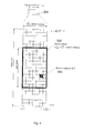
- Fig. 1 The overall architecture of an LTE network is shown in Fig. 1 and a more detailed representation of the E-UTRAN architecture is given in Fig. 2 .
- the LTE architecture supports interconnection of different radio access networks (RAN) such as UTRAN or GERAN (GSM EDGE Radio Access Network), which are connected to the EPC via the Serving GPRS Support Node (SGSN).
- RAN radio access networks
- UE User Equipment
- SGSN Serving GPRS Support Node
- the mobile terminal 110 (called User Equipment, UE, or device) is attached to the access network via the Node B (NB) in the UTRAN and via the evolved Node B (eNB) in the E-UTRAN access.
- NB and eNB 120 entities are known as base station in other mobile networks.
- There are two data packet gateways located in the EPS for supporting the UE mobility - Serving Gateway (SGW) 130 and Packet Data Network Gateway 160 (PDN-GW or shortly PGW).
- SGW mobility - Serving Gateway
- PDN-GW Packet Data Network Gateway
- the eNB entity 120 may be connected through wired lines to one or more SGWs via the S1-U interface ("U" stays for "user plane") and to the Mobility Management Entity 140 (MME) via the S1-MMME interface.
- SGWs S1-U interface
- MME Mobility Management Entity 140
- the SGSN 150 and MME 140 are also referred to as serving core network (CN) nodes.
- CN serving core network
- the E-UTRAN consists of eNodeB 120, providing the E-UTRA user plane (PDCP/RLC/MAC/PHY) and control plane (RRC) protocol terminations towards the user equipment (UE).
- the eNodeB 120 hosts the Physical (PHY), Medium Access Control (MAC), Radio Link Control (RLC), and Packet Data Control Protocol (PDCP) layers that include the functionality of user-plane header-compression and encryption. It also offers Radio Resource Control (RRC) functionality corresponding to the control plane.
- RRC Radio Resource Control
- the eNodeBs are interconnected with each other by means of the X2 interface.
- the eNodeBs 120 are also connected by means of the S1 interface to the EPC (Evolved Packet Core), more specifically to the MME (Mobility Management Entity) by means of the S1-MME and to the Serving Gateway (SGW) by means of the S1-U.
- EPC Evolved Packet Core
- MME Mobility Management Entity
- SGW Serving Gateway
- the S1 interface supports a many-to-many relation between MMEs/Serving Gateways and eNodeBs 120.
- the SGW routes and forwards user data packets, while also acting as the mobility anchor for the user plane during inter-eNodeB handovers and as the anchor for mobility between LTE and other 3GPP technologies (terminating S4 interface and relaying the traffic between 2G/3G systems and PDN GW).
- the SGW terminates the downlink data path and triggers paging when downlink data arrives for the user equipment. It manages and stores user equipment contexts, e.g. parameters of the IP bearer service, network internal routing information. It also performs replication of the user traffic in case of lawful interception.
- user equipment contexts e.g. parameters of the IP bearer service, network internal routing information. It also performs replication of the user traffic in case of lawful interception.
- the MME 140 is the key control-node for the LTE access-network. It is responsible for idle mode user equipment tracking and paging procedure including retransmissions. It is involved in the bearer activation/deactivation process and is also responsible for choosing the SGW for a user equipment at the initial attach and at time of intra-LTE handover involving Core Network (CN) node relocation. It is responsible for authenticating the user (by interacting with the HSS).
- NAS Non-Access Stratum
- the Non-Access Stratum (NAS) signaling terminates at the MME and it is also responsible for generation and allocation of temporary identities to user equipments. It checks the authorization of the user equipment to camp on the service provider's Public Land Mobile Network (PLMN) and enforces user equipment roaming restrictions.
- PLMN Public Land Mobile Network
- the MME is the termination point in the network for ciphering/integrity protection for NAS signaling and handles the security key management. Lawful interception of signaling is also supported by the MME.
- the MME also provides the control plane function for mobility between LTE and 2G/3G access networks with the S3 interface terminating at the MME from the SGSN.
- the MME also terminates the S6a interface towards the home HSS for roaming user equipments.
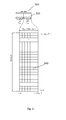
- FIGs 3 and 4 illustrate the structure of a component carrier in the LTE release 8.
- the downlink component carrier of a 3GPP LTE Release 8 is subdivided in the time-frequency domain in so-called subframes, each of which is divided into two downlink slots as shown in figure 3 .
- a downlink slot corresponding to a time period T slot is shown in detail in figures 3 and 4 with the reference numeral 320.
- the first downlink slot of a subframe comprises a control channel region (PDCCH region) within the first OFDM symbol(s).
- PDCCH region control channel region
- Each subframe consists of a give number of OFDM symbols in the time domain (12 or 14 OFDM symbols in 3GPP LTE (Release 8)), wherein each OFDM symbol spans over the entire bandwidth of the component carrier.
- a PRB 330 is defined as consecutive OFDM symbols in the time domain and consecutive sub-carriers in the frequency domain.
- the downlink resources are assigned in resource block pairs.
- a resource block pair consists of two resource blocks. It spans consecutive sub-carriers in the frequency domain and the entire 2 ⁇ modulation symbols of the subframe in the time domain. may be either 6 or 7 resulting in either 12 or 14 OFDM
- a physical resource block 330 consists of x resource elements corresponding to one slot in the time domain and 180 kHz in the frequency domain (further details on the downlink resource grid can be found, for example, in 3GPP TS 36.211, "Evolved universal terrestrial radio access (E-UTRA); physical channels and modulations (Release 10)", version 10.4.0, 2012, Section 6.2, freely available at www.3gpp.org, which is incorporated herein by reference). While it can happen that some resource elements within a resource block or resource block pair are not used even though it has been scheduled, for simplicity of the used terminology still the whole resource block or resource block pair is assigned. Examples for resource elements that are actually not assigned by a scheduler include reference signals, broadcast signals, synchronization signals, and resource elements used for various control signal or channel transmissions.
- a channel resource may be defined as a "resource block" as exemplary illustrated in Figure 3 where a multi-carrier communication system, e.g. employing OFDM as for example discussed in the LTE work item of 3GPP, is assumed. More generally, it may be assumed that a resource block designates the smallest resource unit on an air interface of a mobile communication that can be assigned by a scheduler.
- the dimensions of a resource block may be any combination of time (e.g. time slot, subframe, frame, etc. for time division multiplex (TDM)), frequency (e.g. subband, carrier frequency, etc. for frequency division multiplex (FDM)), code (e.g. spreading code for code division multiplex (CDM)), antenna (e.g. Multiple Input Multiple Output (MIMO)), etc. depending on the access scheme used in the mobile communication system.
- the data are mapped onto physical resource blocks by means of pairs of virtual resource blocks.
- a pair of virtual resource blocks is mapped onto a pair of physical resource blocks.
- the following two types of virtual resource blocks are defined according to their mapping on the physical resource blocks in LTE downlink: Localised Virtual Resource Block (LVRB) and Distributed Virtual Resource Block (DVRB).
- LVRB Localised Virtual Resource Block
- DVRB Distributed Virtual Resource Block
- the eNB In the localised transmission mode using the localised VRBs, the eNB has full control which and how many resource blocks are used, and should use this control usually to pick resource blocks that result in a large spectral efficiency.
- the downlink control signalling is basically carried by the following three physical channels:
- the PCFICH is sent from a known position within the control signalling region of a downlink subframe using a known pre-defined modulation and coding scheme.
- the user equipment decodes the PCFICH in order to obtain information about a size of the control signalling region in a subframe, for instance, the number of OFDM symbols. If the user equipment (UE) is unable to decode the PCFICH or if it obtains an erroneous PCFICH value, it will not be able to correctly decode the L1/L2 control signalling (PDCCH) comprised in the control signalling region, which may result in losing all resource assignments contained therein.
- UE user equipment
- the PDCCH carries control information, such as, for instance, scheduling grants for allocating resources for downlink or uplink data transmission.
- the PDCCH for the user equipment is transmitted on the first of either one, two or three OFDM symbols according to PCFICH within a subframe.
- PDSCH Physical downlink shared channel
- PDCCH Physical downlink shared channel
- Physical uplink shared channel (PUSCH) carries user data.
- Physical Uplink Control Channel (PUCCH) carries signalling in the uplink direction such as scheduling requests, HARQ positive and negative acknowledgements in response to data packets on PDSCH, and channel state information (CSI).
- the frequency spectrum for IMT-Advanced was decided at the World Radio-communication Conference 2007 (WRC-07). Although the overall frequency spectrum for IMT-Advanced was decided, the actual available frequency bandwidth is different according to each region or country. Following the decision on the available frequency spectrum outline, however, standardization of a radio interface started in the 3rd Generation Partnership Project (3GPP). At the 3GPP TSG RAN #39 meeting, the Study Item description on "Further Advancements for E-UTRA (LTE-Advanced)" was approved. The study item covers technology components to be considered for the evolution of E-UTRA, e.g. to fulfill the requirements on IMT-Advanced.
- 3GPP 3rd Generation Partnership Project
- the bandwidth that the LTE-Advanced system is able to support is 100 MHz, while an LTE system can only support 20 MHz.
- the lack of radio spectrum has become a bottleneck of the development of wireless networks, and as a result it is difficult to find a spectrum band which is wide enough for the LTE-Advanced system. Consequently, it is urgent to find a way to gain a wider radio spectrum band, wherein a possible answer is the carrier aggregation functionality.
- carrier aggregation two or more component carriers (component carriers) are aggregated in order to support wider transmission bandwidths up to 100MHz.
- component carrier refers to a combination of several resource blocks.
- component carrier In future releases of LTE, the term "component carrier” is no longer used; instead, the terminology is changed to "cell”, which refers to a combination of downlink and optionally uplink resources.
- the linking between the carrier frequency of the downlink resources and the carrier frequency of the uplink resources is indicated in the system information transmitted on the downlink resources.
- Several cells in the LTE system are aggregated into one wider channel in the LTE-Advanced system which is wide enough for 100 MHz even though these cells in LTE are in different frequency bands. All component carriers can be configured to be LTE Rel. 8/9 compatible, at least when the aggregated numbers of component carriers in the uplink and the downlink are the same. Not all component carriers aggregated by a user equipment may necessarily be Rel. 8/9 compatible.
- Existing mechanism may be used to avoid Rel-8/9 user equipments to camp on a component carrier.
- a user equipment may simultaneously receive or transmit one or multiple component carriers (corresponding to multiple serving cells) depending on its capabilities.
- a LTE-A Rel. 10 user equipment with reception and/or transmission capabilities for carrier aggregation can simultaneously receive and/or transmit on multiple serving cells, whereas an LTE Rel. 8/9 user equipment can receive and transmit on a single serving cell only, provided that the structure of the component carrier follows the Rel. 8/9 specifications.
- link adaptation is fundamental to the design of a radio interface which is efficient for packet-switched data traffic. Unlike the early versions of UMTS (Universal Mobile Telecommunication System), which used fast closed-loop power control to support circuit-switched services with a roughly constant data rate, link adaptation in LTE adjusts the transmitted data rate (modulation scheme and channel coding rate) dynamically to match the prevailing radio channel capacity for each user.
- UMTS Universal Mobile Telecommunication System
- link adaptation in LTE adjusts the transmitted data rate (modulation scheme and channel coding rate) dynamically to match the prevailing radio channel capacity for each user.
- the eNodeB For the downlink data transmissions in LTE, the eNodeB typically selects the modulation scheme and code rate (MCS) depending on a prediction of the downlink channel conditions.
- MCS modulation scheme and code rate
- An important input to this selection process is the Channel State Information (CSI) feedback transmitted by the User Equipment (UE) in the uplink to the eNodeB.
- CSI Channel State Information
- Channel state information is used in a multi-user communication system, such as for example 3GPP LTE to determine the quality of channel resource(s) for one or more users.
- the eNodeB in response to the CSI feedback the eNodeB can select between QPSK, 16-QAM and 64-QAM schemes and a wide range of code rates.
- This CSI information may be used to aid in a multi-user scheduling algorithm to assign channel resources to different users, or to adapt link parameters such as modulation scheme, coding rate or transmit power, so as to exploit the assigned channel resources to its fullest potential.
- a channel resource may be defined as a "resource block" as exemplary illustrated in figure 4 where a multi-carrier communication system, e.g. employing OFDM as for example discussed in the LTE work item of 3GPP, is assumed. More generally, it may be assumed that a resource block designates the smallest resource unit on an air interface of a mobile communication that can be assigned by a scheduler.
- the dimensions of a resource block may be any combination of time (e.g. time slot, subframe, frame, etc. for time division multiplex (TDM)), frequency (e.g. subband, carrier frequency, etc. for frequency division multiplex (FDM)), code (e.g. spreading code for code division multiplex (CDM)), antenna (e.g. Multiple Input Multiple Output (MIMO)), etc. depending on the access scheme used in the mobile communication system.
- channel quality information for each and all resource blocks and each and all users should be always available.
- this is most likely not feasible or even impossible. Therefore, reduction or compression techniques are required so as to reduce the channel quality feedback signalling overhead, e.g. by transmitting channel quality information only for a subset of resource blocks for a given user.
- subband which consists of multiple frequency-adjacent resource blocks.
- the resource grants are transmitted from the eNodeB to the UE in downlink control information (DCI) via PDCCH.
- DCI downlink control information
- the downlink control information may be transmitted in different formats, depending on the signaling information necessary.
- the DCI may include:
- the DCI may include further information, depending on the signaling information necessary, as also described in Section 9.3.2.3 of the book " LTE: The UMTS Long Term Evolution from theory to practice” by S. Sesia, I. Toufik, M. Baker, Apr. 2009, John Wiley & Sons, ISBN 978-0-470-69716-0 , which is incorporated herein by reference.
- the DCI may further include HARQ related information such as redundancy version (RV), HARQ process number, or new data indicator (NDI); MIMO related information such as pre-coding; power control related information, etc.
- Other channel quality elements may be the Precoding Matrix Indicator (PMI) and the Rank Indicator (RI). Details about the involved reporting and transmission mechanisms are given in the following specifications to which it is referred for further reading (all documents available at http://www.3gpp.org and incorporated herein by reference):
- the resource block assignment specifies the physical resource blocks which are to be used for the transmission in uplink or downlink.
- the modulation and coding scheme defines the modulation scheme employed for the transmission such as QPSK, 16-QAM or 64-QAM. The lower the order of the modulation, the more robust is the transmission. Thus, higher-order modulations, such as 64-QAM, are typically used when the channel conditions are good.
- the modulation and coding scheme also defines a code rate for a given modulation, i.e. the number of information bits carried in a predefined resource. The code rate is chosen depending on the radio link conditions: a lower code rate can be used in poor channel conditions and a higher code rate can be used in the case of good channel conditions. "Good” and “bad” here is used in terms of the signal to noise and interference ratio (SINR). The finer adaptation of the code rate is achieved by puncturing or repetition of the generic rate depending on the error correcting coder type.
- FIG 6 shows an example of an MCS table used in LTE release 11 to determine the modulation order ( Q m ) used in the physical downlink shared channel.
- the levels between 0 and 9 in downlink usually represent employing of the robust QPSK modulation.
- LTE release 11 foresees an MCS table which essentially has the same structure of the MCS table for the downlink channel.
- the QPSK modulation scheme is represented by the MCS levels between 0 and 9 (for more details refer to 3GPP TS 36.213, "Evolved Universal Terrestrial Radio Access (E-UTRA); Physical layer procedures", version 11.1.0, sections 7 and 8, respectively and in particular Tables 7.1.7.1-1 for downlink and 8.6.1-1 for uplink).
- the remaining levels specify configurations with higher-level modulation schemes.
- the levels in the MCS table corresponding to the higher indexes (17 to 28) represent the 64-QAM modulation scheme.
- the QPSK and 16-QAM modulation schemes are also indicated as low-order modulation schemes when compared to the 64-QAM modulation scheme.
- the term "lower-order modulation scheme" is to be understood as any modulation order lower than the highest supported modulation order.
- the first column of the MCS table defines an index which is actually signaled, for instance in the DCI, in order to provide a setting for modulation and coding scheme.
- the second column of the MCS table provides the order of the modulation associated with the index, according to which order 2 means QPSK, order 4 means 16-QAM and order 6 means 64-QAM.
- the third column of the table includes transport block size index which refers to predefined sizes of transport blocks and thus also to a coding rate (amount of redundancy added to the data).
- the transport block size (TBS) index in the third column of the MCS table refers to a TBS table (cf.
- Table 7.1.7.2.1-1 in the 3GPP TS 36.213, cited above which includes rows with a first column corresponding to the number of the TBS index and the following columns specifying the transport block sizes for the respective numbers of resource blocks, which are signaled in the DCI and in particular in the resource block allocation (RBA) part thereof.
- RBA resource block allocation
- Transport block is a data unit which includes data to be transmitted and which are provided for the transmission by the higher layers, i.e. mapped onto the physical resources in accordance with the control information including scheduling information and/or according to the settings by the higher layers. Transport blocks are mapped on the respective resource blocks, i.e. in general onto fixed-size time slots (time domain portions).
- HetNet Heterogeneous Networks
- a typical HetNet deployment as currently discussed within 3GPP consists of macro and pico cells.
- Pico cells are formed by low power eNBs that may be advantageously placed at traffic hotspots in order to offload traffic from macro cells.
- Macro and pico eNBs implement the scheduling independently from each other. The mix of high power macro cells and low power pico cells can provide additional capacity and improved coverage.
- a terminal such as a user equipment (UE) connects to the node with the strongest downlink signal.
- UE user equipment
- the area surrounding the low power eNBs and delimited by a solid line edge is the area where the downlink signal of the low power eNB is the strongest. User equipments within this area will connect to the appropriate low power eNB.
- CRE cell rage expansion
- Figure 5A illustrates such a HetNet scenario where various pico cells are provided in the area of one macro cell.
- the range expansion zone (CRE) is delimited in figure 5A by a dashed edge.
- the pico cell edge without CRE is delimited by a solid line edge.
- Various UEs are shown located in the various cells.
- Figure 5B schematically illustrates the concept of a HetNet scenario including a macro eNB and a plurality of pico eNB serving respectively a plurality of UEs located in their coverage areas.
- the macro eNB is the single dominant interferer for pico UEs, i.e. for UEs being connected to the pico eNB. This is especially true for pico UEs at the cell edge when using CRE.
- Cell-edge users served by a pico eNodeB usually have relatively low received signal strength, especially if they are located at the border of a pico cell with CRE and suffer from strong intercell interference.
- the major interferer is the eNodeB serving the macro cell in the Heterogeneous Network, which usually transmits subframes at a high transmission power.
- Inter-Cell Interference Coordination is to maximize the multi-cell throughput subject to power constraints, inter-cell signaling limitations, fairness objectives and minimum bit rate requirements.
- Figure 7 shows an exemplary downlink transmission scenario in which two UEs are served by an eNB.
- high or low order modulation schemes can be used for data transmissions.
- the set of currently supported modulation schemes in LTE consists of QPSK, 16-QAM and 64-QAM.
- the modulation and coding scheme (MCS) that is used for transmissions of physical downlink shared channels (PDSCH) transmissions is indicated by the MCS field within the downlink control information (DCI).
- DCI downlink control information
- the current Rel-11 MCS field has a fixed length of five bits. This results in 32 code points that are used for indicating 32 combinations of modulation scheme and code rate of the channel coder.
- the code rate is determined by the transport block size that is mapped onto a set of allocated resource blocks (RBs).
- the interpretation of the MCS field code points is given by the specified MCS table.
- the table maps each code points described as MCS index to a combination of modulation order and transport block size (TBS) index.
- the modulation order describes the number of bits that are mapped onto a single modulation symbol.
- the current Release-11 table supports modulation order 2, 4 and 6 which corresponds to QPSK, 16-QAM and 64-QAM.
- the TBS index is linked to an entry of the TBS table which contains a transport block size depending in the number of allocated RBs. Each TBS index corresponds therefore a certain spectral efficiency in terms of bits transmitted per RB.
- the current Release-11 MCS table is shown in Figure 6 . It can be seen that the table contains three entries without TBS index. These MCS indices are used for retransmissions of erroneous transport blocks. The indication of the transport block size is not required in this case since the size is known from the initial transmission. Each MCS index corresponds to a certain SINR level at which the combination of modulation scheme and code rate that is determined by the transport block size can be used without exceeding a certain block error probability. Assuming a block error probability of 0.1, the current Release-11 table approximately covers the SINR range between -7 dB and 20 dB; the MCS table supports 27 TBS indices, and increasing the TBS index by one corresponds approximately to an SINR level difference of 1 dB.
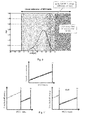
- Figure 8 shows the RB SINR level distributions of two typical UE within a heterogeneous network deployment as evaluated during performance studies for Release-11. The results have been achieved by means of system level distributions and the curves correspond to a cell-center UE with very high average SINR level and a cell-edge UE with very low average SINR level. From Figure 8 it can be seen that a large fraction of SINR samples of the cell-center UE is not covered by the current Rel-11 MCS table.
- the aim of the present invention is to provide an efficient and robust approach for covering, with the modulation and coding schemes of the adaptive modulation and coding, higher SINR conditions.
- the sets differ by the entries of the highest-order modulation.
- the transmitter and the receiver are able to select between the two (or more) sets.
- an apparatus for receiving data from a network node in a communications system, the apparatus comprising a control information reception unit for receiving scheduling information specifying resources on which data are to be transmitted and including a modulation and coding indicator; a modulation and coding selection unit capable of selecting modulation and coding from a set of predefined modulation and coding schemes according to the modulation and coding indicator, a set selection unit for selecting the set of predefined modulation and coding schemes from at least two predefined sets -- the first set and the second set, which have a plurality of modulation and coding schemes in common and differ in that the second set further includes an additional modulation with an order higher than any modulation in the first set, and the first set and the second set have the same size; and a data transmission unit for transmitting the data on the scheduled resources using the selected modulation and coding.
- an apparatus for transmitting data in a communications system, the apparatus comprising: a control information transmission unit for transmitting scheduling information specifying resources on which the data are to be transmitted and including a modulation and coding indicator; a modulation and coding selection unit capable of selecting modulation and coding from a set of predefined modulation and coding schemes according to the modulation and coding indicator, a set selection unit for selecting the set of predefined modulation and coding schemes from at least two predefined sets -- the first set and the second set, which have a plurality of modulation and coding schemes in common and differ in that the second set further includes an additional modulation with an order higher than any modulation in the first set, and the first set and the second set have the same size; and a data reception unit for receiving the data on the scheduled resources using the selected modulation and coding.
- the modulation and coding schemes in each of the sets are associated with the values of modulation and coding indicator, a plurality of the modulation and coding indicator values refer to the respective same modulation and coding schemes in the first and in the second set, and the remaining modulation and coding indicator values refer in the second set to the highest-order modulation and in the first set to modulation(s) of one or more lowest order(s).
- M lowest values of the modulation and coding indicator refer to: the modulation and coding schemes with the lowest-order modulation in the first set and the modulation and coding schemes with the highest-order modulation in the second set.
- the second set may be constructed in such a way that it does not include modulation with the lowest order included in the first set.
- K values of the modulation and coding indicator refer to the same modulation and coding schemes with the lowest-order modulation in both the first and the second set
- L values refer to the modulation and coding schemes with the lowest-order modulation in the first set and the modulation and coding schemes with the highest-order modulation in the second set
- the remaining values of the modulation and coding indicator refer to the same modulation and coding schemes lower than the highest-order modulation
- the K values correspond to the first K values of the index and the L values are L values immediately following the K values.
- the modulation and coding indicator is associated with a modulation and coding scheme including a modulation order and a size indicator indicating at least one of (i) the number of bits in a transport block which is to be mapped onto physical resources and (ii) retransmission without specific indication of the transport block size.
- a method for receiving data from a network node in a communications system, the method comprising the steps of: receiving scheduling information specifying resources on which data are to be transmitted and including a modulation and coding indicator; selecting modulation and coding from a set of predefined modulation and coding schemes according to the modulation and coding indicator, selecting the set of predefined modulation and coding schemes from at least two predefined sets -- the first set and the second set, which have a plurality of modulation and coding schemes in common and differ in that the second set further includes an additional modulation with an order higher than any modulation in the first set, and the first set and the second set have the same size; and transmitting the data on the scheduled resources using the selected modulation and coding.
- a method for transmitting data in a communications system comprising: transmitting scheduling information specifying resources on which the data are to be transmitted and including a modulation and coding indicator; selecting modulation and coding from a set of predefined modulation and coding schemes according to the modulation and coding indicator, selecting the set of predefined modulation and coding schemes from at least two predefined sets -- the first set and the second set, which have a plurality of modulation and coding schemes in common and differ in that the second set further includes an additional modulation with an order higher than any modulation in the first set, and the first set and the second set have the same size; and receiving the data on the scheduled resources using the selected modulation and coding.
- the selection of the set of modulation and coding schemes is performed based on a set selection indicator exchanged between the transmitter and the receiver.
- the transmitter of data may perform scheduling for the transmission and/or reception resources and indicate the settings to the receiver of data.
- the transmitter may indicate to the receiver also the choice of the set of modulation and coding schemes.
- the set selection indicator may be signaled by means of a higher-layer signaling.
- the scheduling information is signaled on physical layer and the set selection indicator is signaled on the MAC (medium access control) or RRC (radio resource control) layer.
- MAC medium access control
- RRC radio resource control
- the set selection indicator may be signaled on the same layer as the scheduling information, for example on the physical layer. For instance, it may be signaled within the control information which includes the scheduling information.
- Some fields used for other purposes may be used to signal the set selection indicator.
- the redundancy version field used for signaling the version of the redundancy for the hybrid ARQ protocol or new data indicator used for distinguishing between first transmission and retransmission may be used.
- some of the values (or a single value) of the RV or NDI may be used to indicate that a first set is to be used and some values (or a single value) of the RV or NDI may be used to indicate that a second set shall be used.
- the selection of the set of modulation and coding schemes is performed by both receiver and transmitter of the data based on the channel conditions of their communication channel. For instance, the transmitter of data receives indication of the channel conditions from the receiver of the data and selects the set accordingly. The receiver also selects the set according to the channel conditions reported to the transmitter. This approach is implicit and does not require any additional signaling. The transmitter and receiver use the same rules to select the set in dependency of the channel conditions reported.
- the set selection indicator is signaled (transmitted/received) less frequently than the scheduling information.
- a computer-readable medium is provided with a computer-readable program thereon, which, when executed on the computer, implements the steps of the method according to the present invention.
- the present invention is applied to LTE system (for instance Release-11 of the LTE).
- the data transmitter may be the eNodeB and the data receiver may ne the terminal.
- the data are transmitted over PDSCH and the control information including the scheduling information is transmitted on the PDCCH.
- the scheduling information may be carried by the DCI.
- the DCI may include, as is the case in the Release-11 LTE, an MCS index specifying the modulation and coding scheme to be used from among a set of modulation and coding schemes, which are predefined in a so-called MCS table.
- MCS table In compliance with the invention, more than one MCS tables may be defined, from which one is used at a time.
- the MCS table is selected based on the signaled information at the terminal or based on the channel conditions.
- the MCS table is chosen by the eNodeB based on channel conditions and the choice may be or does not need to be signaled to the terminal.
- the embodiments are outlined in relation to radio access schemes according to 3GPP LTE (Release 8/9) and LTE-A (Release 10/11) mobile communication systems, which were partly discussed in the technical background section above.
- the invention may be used, for example, in a mobile communication system such as 3GPP LTE-A (release 11) communication systems as described in the technical background section above, but the invention is not limited to its use in these particular exemplary communication networks.
- the invention may be, for example, used in non-3GPP systems such as WIMAX.
- the present invention can be advantageously applied as a strategy for indicating the modulation and coding scheme (MCS) for data transmissions in an LTE system.
- MCS modulation and coding scheme
- the currently supported set of modulation schemes in Release 11 consists of QPSK, 16-QAM and 64-QAM.
- higher modulation orders may be desirable for achieving higher spectral efficiencies.
- 256-QAM may be applied to further extend the range of spectral efficiencies configurable. First performance evaluations have shown that the use of 256-QAM is expected to be reasonable with SINR levels of at least 20 dB.
- the MCS that is used for PDSCH and PUSCH transmissions has up to now been indicated in an MCS field within the downlink control information (DCI).
- DCI downlink control information
- the robustness of the signaling with respect to the transmission errors should also be maintained as far as possible.
- concepts for mapping code points of the Release-11 MCS field to modulation and coding schemes comprising 256-QAM is provided by reinterpreting code points of low order modulation schemes.
- MCS table By a certain set of entries for 256-QAM with different TBS indices.
- the MCS field within the DCI has to be extended accordingly, in order to cover the resulting increased set of modulation and coding schemes.
- the minimum MCS field extension consists of a single additional bit which doubles the number of MCS field code points. Since the current Release-11 MCS field has a length of five bits, the number of code points would be extended from 32 to 64. The set of modulation and coding schemes could therefore be extended by 32 new entries for 256-QAM.
- the current Release-11 TBS table does not support transport block size large enough for efficiently making use of 256-QAM which supports very high spectral efficiencies obtained by mapping eight bits onto a single 256-QAM modulation symbol.
- the TBS table should advantageously be extended by further rows for transport blocks larger than the blocks currently supported. This corresponds to the support of higher SINR levels.
- the DCI carrying the MCS indicator is mapped onto a set of fixed-size resources. Accordingly, the size of the DCI determines the robustness of the signalling carried thereby since it determines how much redundancy is to be used for the transmission of the DCI and thus, also of the MCS indicator included therein. The smaller the DCI that is mapped onto a certain resource, the larger is the redundancy and hence the robustness. Thus, the DCI size should in general be kept as small as possible.
- Another problem of the above described approach of extending the MCS index by a further bit is that the number of 32 new MCS indices is much larger than the set of code rates currently supported, and hence also of the transport block sizes which can be supported by the 256-QAM. Extending the modulation order would also further require a set of additional code points in the TBS index.
- the problem underlying the present invention is based on the observation that it is not likely for a UE to experience an SINR fluctuation of more than 50 dB, if the position and hence pathloss and shadowing conditions do not change significantly, which is expected to be the case also for the indoor applications. Therefore, the aim is to primarily cover the expected SINR level distribution of different UEs by a proper MCS table design.
- an apparatus which is to be able to receive the data may include a control information reception unit for receiving scheduling information specifying resources on which data are to be transmitted and including a modulation and coding scheme indicator and a data transmission unit for transmitting the data on the scheduled resources using the modulation and coding scheme indicated by the modulation and coding scheme indicator.
- the data receiving apparatus is not necessarily a terminal. It may be also a relay or a base station (for instance in uplink) or any other network node.
- an apparatus for receiving data in the communications system in accordance with the present invention comprises also a modulation and coding selection unit capable of selecting modulation and coding from a set of predefined modulation and coding schemes according to the modulation and coding indicator; and a set selection unit for selecting the set of predefined modulation and coding schemes from at least two predefined sets -- the first set and the second set, which have a plurality of modulation and coding schemes in common and differ in that the second set further includes an additional modulation scheme with an order higher than any modulation scheme in the first set, and the first set and the second set have the same size.
- the above apparatus is an apparatus which receives the data and the scheduling information.
- the present invention also relates to a corresponding apparatus for transmitting the data in a communications system and comprising a control information transmission unit for transmitting to the terminal scheduling information specifying resources on which the terminal is to transmit data to the network node and including a modulation and coding indicator; a modulation and coding selection unit capable of selecting modulation and coding from a set of predefined modulation and coding schemes according to the modulation and coding indicator; a set selection unit for selecting the set of predefined modulation and coding schemes from at least two predefined sets -- the first set and the second set, which have a plurality of modulation and coding schemes in common and differ in that the second set further includes an additional modulation scheme with an order higher than any modulation scheme in the first set, and the first set and the second set have the same size; and a data reception unit for receiving the data from the terminal on the scheduled resources using the selected modulation and coding.
- the receiving apparatus may be a terminal, while the transmitting apparatus may be an eNodeB or a relay. However, the receiving apparatus may also be a relay node and the transmitting apparatus may be an eNodeB.
- the present invention is not limited to a particular direction uplink/downlink and also not to a particular type of the network nodes.
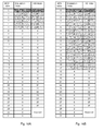
- the modulation and coding schemes in each of the sets may be associated with the values of modulation and coding indicator, wherein a plurality of the modulation and coding indicator values refer to the respective same modulation and coding schemes in the first and in the second set, and the remaining modulation and coding indicator values refer in the second set to the highest-order modulation and in the first set to the lowest-order modulation(s). It is noted that it is not necessarily only one lowest-order modulation. As can be seen in Figure 10B , the remaining modulation and coding indicator values may refer in the second set to the highest-order modulation and in the first set to modulation(s) of one or more lowest order(s). For example, Figure 10B shows that the modulation and coding schemes using modulation order 8 (256-QAM) replace not only the schemes of modulation order 2 (QPSK) but also some schemes of modulation order 4 (16-QAM) from the table of Figure 6 .
- modulation and coding schemes using modulation order 8 256-QAM
- QPSK modulation
- the approach of the present invention when exemplarily applied to the above described situation in LTE Release-11, enables to reinterpret the current MCS indices in order to support a new modulation scheme, such as 256-QAM for PDSCH transmissions without extending the MCS field within the DCI by further bits.
- a new modulation scheme such as 256-QAM for PDSCH transmissions without extending the MCS field within the DCI by further bits.
- This is advantageously achieved by replacing some entries for a low-order modulation by entries for a new, high-order modulation.
- the rationale is that an UE that will be a candidate for PDSCH transmissions with higher-order modulation schemes will probably not be used at the same time for transmissions with low-order modulation schemes. This would be, for instance, the case for indoor UEs with restricted mobility which are located close to a base station (eNB).
- eNB base station
- the present invention is not limited thereto.
- higher-order modulations may be applicable in future.
- the modulation schemes selectable for the transmission are generally not limited to quadrature amplitude modulations and may include any other frequency, phase, amplitude modulation or combinations thereof including the trellis and coset coding modulation.
- the first set may include modulation and coding schemes including QPSK, 16-QAM and 64-QAM and the second set may include modulation and coding schemes including the same modulations and, in addition, 256-QAM. It is also be possible to construct a second set which does not include the modulation of the lowest order at all, such as QPSK in this example.
- the present invention is not limited to two alternative sets of modulation and coding schemes. A plurality of sets may be employed. Additional alternative MCS tables selectable enable finer adaption of the SINR range covered by the terminal channel conditions and/or supporting of a generally higher SINR range. This may be particularly advantageous for communication systems with various kinds of deployment scenarios resulting in different channel conditions such as heterogeneous cellular and/or mobile networks.
- FIGS. 10A and 10B show examples of an MCS table in accordance with an embodiment of the present invention.
- the M lowest values of the modulation and coding scheme indicator, M being an integer refer to:
- the second set does not include modulation with the lowest order included in the first set.
- this is only an example, and - as is clear from the example of Figure 10A - other arrangements may be beneficial, which also include schemes with the lowest-order modulation.
- Figure 10A shows an arrangement, according to which only some (not all) of the modulation and coding schemes with the lowest-order modulation are replaced with the highest-order modulation.
- the modulation order of M lowest MCS indices in the table shown in Figure 6 is set to 8 (from 2), which corresponds to 256-QAM (instead of QPSK).
- the present invention is not limited thereto and any M may be selected.
- the M first indices of the first table (such as the table of Figure 6 ) are reinterpreted in the second table.
- the remaining indices of both tables refer to the same modulation and coding schemes.
- the M first indices correspond to the indices belonging to the lowest modulation order and, in particular, correspond to the lowest spectral efficiencies.
- the TBS indices for the MCS indices with the overwritten modulation order are set to values (cf. values higher than 26 in the exemplary MCS tables), which are linked with transport block sizes that are larger than the currently supported sizes for modulation orders of up to 6, which corresponds to 64-QAM.
- the maximum TBS index in Release-11 is 26.
- the TBS table has to be then extended by entries for TBS indices larger than 26.
- the TBS indices of the adapted entries range from 26 to 31 in the first adapted MCS table ( Figure 10A ), and from 26 to 43 in the second adapted MCS table ( Figure 10B ).
- the lowest TBS index (26) for 256-QAM is the same as the highest for 64-QAM. That means that a certain spectral efficiency can be achieved by using either 64-QAM with high code rate, or 256-QAM with low code rate. Which one will be used for data transmissions depends on the channel conditions and the transmitter and receiver characteristics. The same approach is used in Release-11 for the transitions between QPSK and 16-QAM, and between 16-QAM and 64-QAM. However this is only an example which means that, in general, this "repetition" does not have to be applied for the present invention.
- the TBS table extension is immaterial for the present invention. It can be assumed here that the TBS table is extended by a sufficient number of entries in order to support the required set of code rates for the modulation and coding schemes including the new 256-QAM. It is further noted that the present invention is not limited to the formats of signaling applied in the LTE.
- the set of modulation and coding schemes may correspond to the MCS table as defined in LTE, however does not necessarily need to. Accordingly, the present invention may support modulation and coding schemes given by the modulation order (since modulation type is fixed) and by the transport block size index referring to particular transport block sizes depending on the number of resource blocks allocated (signaled within the scheduling information).
- the present invention may apply also to modulation and coding schemes with different modulation types and/or orders.
- the "coding" may be indicated by means of transport block size or by means of the coding type applied or in any other means.
- the modulation and coding scheme is not limited to include only a modulation and coding and it may include further indications related to the data format such as redundancy version (the case for the uplink in LTE) or other parameters.
- the relation between the MCS index and the spectral efficiency of the Release-11 MCS table is shown schematically in Figure 11 in the top graph.
- the spectral efficiency that is determined by the TBS is in the current MCS table (shown in Figure 6 ) increased essentially linearly with the MCS index.
- the reoccurring of certain spectral efficiencies at switching points between different modulation orders is neglected in the representation of Figure 11 for the sake of clarity.
- the graphs on the bottom of Figure 11 show how the spectral efficiencies are changed for low MCS indices of the MCS tables shown in Figure 10A and 10B , which now support 256-QAM. Since each spectral efficiency value correspond to a certain SINR level, it can be seen that the SINR range covered by each MCS table is shifted from lower to higher SINR levels.
- the graph on the left side of Figure 11 illustrates the general case in which there are M first values of the first MCS table (Table of Figure 6 ) replaced by the entries with highest-order modulation, namely the 256-QAM.
- Each UE is expected to be operated within a certain SINR range that is determined by its position (location with respect to the base station) and multipath channel properties in particular in terms of small-scale fading.
- the idea underlying the present invention is to reinterpret MCS indices and thus shift the SINR range that is covered by the MCS table rather than to extend the SINR range. It is expected that the current SINR range in LTE of approximately 27 dB is sufficient for all UEs. As is understood by those skilled in the art, an appropriate shift should be applied in order to cover the real SINR levels experienced by the UEs in the cell of the communications system.
- the present invention may be advantageously employed in that two or more different MCS tables, which cover different SINR ranges, are defined in the communication standard such as the LTE specification, and each terminal is informed about the MCS table to be used for the PDSCH transmissions. Exemplary ways in which the terminals obtain the information regarding the MCS table shall be discussed later.
- different MCS tables are to cover different SINR ranges, it can also be beneficial to allow the support of different MCS tables for different subframe sets or subbands in order to support different interference conditions on these sets of radio resources.
- different MCS tables may be supported for low power subframes than for the regular subframes.
- a terminal may automatically select a first table for the transmission in the low power subframes and a second table for the transmission in the remaining subframes.
- transmission in the low power subframes may employ an MCS table with more lower-order modulations in order to be more robust, while the transmission in the remaining subframes may use another MCS table including a higher-order modulation in accordance with any embodiment of the present invention.
- Low-power subframes are employed especially in the field of radio transmission and, in particular, for the heterogeneous networks. Accordingly, some subframes are transmitted with a reduced power, which is generally kept lower than the transmission power of the remaining (regular) frames.
- the power may be limited by a threshold.
- the limited power frames are particularly useful at the borders of the pico cells at which the pico cell receiver and the larger cell receiver signals may interfere. They enable a terminal to receive data from pico cells even when the base station of the macro cell is more powerful (cf. Figures 5A and 5B and the related description above).
- different component carriers may employ different MCS tables, meaning that the MCS table can be selected by the terminal differently for different component carriers.
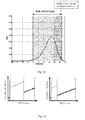
- Figure 12 shows exemplarily the RB SINR level distribution of a typical cell-center UE and the corresponding appropriate MCS table shift that covers more or less all SINR samples.
- the SINR range width has not been changed but rather the SINR range has been shifted towards the higher SINRs. Accordingly, in the above described embodiment, linear shift of the SINR range covered by the MCS table is performed.
- K values of the modulation and coding indicator refer to the same modulation and coding schemes with the lowest-order modulation in both the first and the second set
- L values, L being an integer refer to the modulation and coding schemes with the lowest-order modulation in the first set and the modulation and coding schemes with the highest-order modulation in the second set
- the remaining values of the modulation and coding indicator refer to the same modulation and coding schemes lower than the highest-order modulation.
- the K values are the K lowest values of the modulation and coding indicator and the L values are the L values following the K values.
- FIG. 13A and 13B An example of possible MCS tables according to such advantageous implementation is illustrated in Figures 13A and 13B .
- the tables may be respectively advantageous for two different UEs with different average channel conditions.
- there may be also a single one most robust modulation and coding scheme (K 1) left (for instance also in the first position in the MCS table, i.e. having the lowest index value in the set).
- K may also be larger.
- M, K, L in the above embodiments is to be performed according to the scenarios, in which the devices of the communications system taking part on the communication using the adaptive modulation and coding typically operate.
- M, K, L measurements/estimation of the SINR for the desired deployment scenarios should be performed and based thereon decided, which SINR range is to be covered by the respective sets of the modulation and coding schemes.
- the communication system nodes may be configured to use the table of Figure 6 as the first set and the table of Figure 10A (or alternatively 10B or alternatively 13A or 13B) as the second set.
- the communication system nodes may be configured to use the table of Figure 6 as the first set and the table of Figure 10A (or alternatively 10B or alternatively 13A or 13B) as the second set.
- This scenario has an advantage of low signalling overhead when the selection of the set is to be signalled from the transmitter of data to the receiver of data.
- the present invention is not limited thereto.
- Figure 15 shows how the SINR samples of a typical cell-center UE (a UE which operates in a range of higher SINRs) are covered by the MCS table shown in Figure 13A .
- the MCS indices for the low SINR values can always be used for data transmissions on resource blocks with higher SINR levels. However, the opposite is not possible since for the lower SINRs the channel quality would be low and consequently, the error rate to high to be able to decode the data.
- the MCS indices for very robust data transmissions are beneficial for transmissions of very error sensitive messages such as control messages or user data transmissions with very high quality of service (QoS) requirements in terms of error robustness, which may be in particular the delay sensitive services in which the retransmissions are not feasible. This may be for instance real-time conversational (and/or streaming) applications.
- QoS quality of service
- the modulation and coding scheme indicator may be associated with a particular modulation and coding scheme including: a modulation order and a size indicator indicating at least one of (i) the number of bits in a transport block which is to be mapped onto physical resources and (ii) retransmission without specific indication of the transport block size.
- a modulation order and a size indicator indicating at least one of (i) the number of bits in a transport block which is to be mapped onto physical resources and (ii) retransmission without specific indication of the transport block size.
- the first 29 entries of the respective tables associate the MCS index 0 to 28 with respective combinations of a modulation order and a TBS index.
- the last three indices 29 to 31 indicate for three respective modulation orders 2, 4, and 6 "reserved" which means that these values are reserved for HARQ retransmissions performed with the indicated modulation order.
- No specific size/number of the transport blocks is necessary to be signaled since the size is determined in a predefined manner from the
- an entry is added indicating retransmission without specifying explicitly the transport block size and the number of transport block as it is done by the TBS index.
- the reservation of a certain MCS index for HARQ retransmissions with 256-QAM may be performed by reserving the first index (the lowest value of the modulation and coding indicator).
- FIG. 16A An example, in which MCS index 0 is used for indicating the retransmissions for the highest-order modulation, namely for 256QAM, is shown in Figures 16A and 16B .
- the 5 indices of the MCS index following the first index (with value 0) are dedicated to modulation and coding schemes with the highest-order modulation (order 8, corresponding to 256-QAM), followed by the same schemes as those of Figure 6 for the index values from 6 to 31.
- Figure 16B shows an example, in which the first MCS index (with value 0) is followed by 17 schemes employing the highest-order modulation. Again, the remaining schemes are the same schemes as those of Figure 6 for the index values from 18 to 31.
- the reservation of an MCS Index for HARQ retransmissions may also be applied together with maintaining some entries of the lowest-order modulation (as described with reference to Figure 13 ). Both variants are possible: the retransmission index may be the first one in the table or it may follow the M lowest-order modulation schemes. Combination of providing an HARQ-reserved index with maintaining some of the most robust modulation and coding schemes provides a high degree of flexibility. HARQ retransmissions with 256-QAM are possible and at least one MCS index is kept for very robust data transmissions using QPSK.
- exemplary embodiments are provided concerning the performing of the selection of the set of modulation and coding schemes from the predefined sets. It is noted that any of the following exemplary embodiments may be combined with any of the previously described embodiments.
- the choice of the set is performed by the network node, signaled to the terminal, and the selection of the set at the terminal is performed accordingly, wherein the signaling is a higher-layer signaling less frequent than the signaling of the modulation and coding scheme indicator.
- the MCS table is indicated by higher layer signaling.
- the indication of the set (MCS table) is carried out by either MAC or RRC messages which are sent in downlink direction (from the eNB to the UE, or alternatively from the eNB to the relay or from the relay to the UE).
- This approach yields a semi-static configuration of the used MCS table by means of higher layer information elements.
- the term semi-static implies that in comparison with the dynamic scheduling, allocation and MCS control, the MCS table selection is performed less frequently. The frequency may be selected according to the requirements - if the channel conditions change so that a change of the MCS table may be beneficial, then the new table is indicated.
- the data transmitting node thus chooses the MCS table, signals the choice by means of a set indicator to the data receiving node and the data receiving node selects then the set (MCS table) according to the received set indicator.
- This embodiment provides an advantage of simple and robust implementation.
- the switching between four MCS tables would require only two additional bits in the higher-level signaling, the switching between two MCS tables (for example the standard Release-11 table as shown in Figure 6 and the adapted table for 256-QAM) would require only one bit.
- the present invention is not limited to signaling of the set selection indicator within the higher-layer signaling.
- the choice of the set is performed by the network node, signaled to the terminal, and the selection of the set at the terminal is performed accordingly, wherein the signaling is carried on the same layer as the signaling of the modulation and coding indicator, but less frequently.
- the indication may be advantageously conveyed by reusing code points of the DCI.
- This approach yields a dynamic MCS table adaptation that can be changed from subframe to subframe but does not necessarily have to be changed.
- the set selection indication may be included within the scheduling information.
- the NDI indicator is an indicator for distinguishing between the first transmission of data and data retransmission. Accordingly, it is usually a one-bit flag. This is also the case in LTE.
- the following interpretation of the signaling may be enabled or disabled by means of a semi-static configuration, for instance by a higher layer protocol such as RRC or MAC:
- toggled means set to indicate new data, i.e. first transmission of the data.
- non-toggled means set to indicate retransmission of data.
- the selection of the set of modulation and coding schemes is performed based on whether the data to be modulated/coded are data transmitted for the first time (new data) or a retransmission.
- This selection may be performed at the transmitter an the receiver in the same way, and in particular at the receiver based on the new data indicator.
- the above example is based on the observation that for the first transmission, the assumption of good channel conditions may be made and thus, the second set of modulation and coding schemes including the highest-order modulation may be used. If the transmission was not successful, so that a retransmission is necessary, this may indicate that the channel conditions are worse and thus, the first set is selected, which does not include the highest-order modulation.
- the interpretation does not need to be based (only) on the NDI.
- the redundancy version (RV) may be used for this purpose.
- the following interpretation of the signaling could be enabled or disabled by means of a semi-static configuration, for instance by a higher layer protocol such as RRC or MAC:
- the 5-bit MCS field refers to the MCS table size of 32 entries as illustrated in Figure 6 and to an advantageous embodiment of the present invention, according to which the first set is the current LTE table shown in Figure 6 and the second set is a table with the same number of entries but including instead of some entries with lowest-order modulation new entries with a modulation, the order of which is higher than any modulation on the first set.
- redundancy version indicator (may correspond to a field in a control information) specifies the version of redundancy to be applied when retransmitting data. Namely, hybrid ARQ schemes performs retransmissions by using different redundancy schemes in order to achieve higher diversity and better probability of correct decoding. Thus, the redundancy version is also an indication for the retransmitting and, in addition, for a number of retransmissions performed so far. Accordingly, this information may be also used for switching between the sets of modulation and coding schemes. Redundancy version 0 is used with no retransmissions and may thus advantageously be used to indicate selection of the second set of modulation and coding schemes, which includes the highest-order modulation (256-QAM).
- the remaining values of the RV may be used to select the first set without the highest-order modulation.
- the different redundancy version values may be used to select different sets (i.e. select between more than 2 MCS tables). The higher the number of retransmissions, the more robust set of modulation and coding schemes is selected preferably.
- the selection of the set is performed by both terminal and network node based on the terminal's channel conditions reported from the terminal to the network node. Accordingly, no exchange of an explicit indication is necessary in order to select the set of the modulation and coding schemes.
- the MCS table may be determined by the average channel quality of the UE that is captured by the wideband CQI which is reported from the UE to the eNB. This approach does not require any additional signaling and automatically adapts the MCS table to the prevailing channel conditions. It has to be specified, which wideband CQI values yield an MCS table switching so that the switching (selecting of an MCS table different from the currently employed MCS table) is performed in the same way at the transmitter and the receiver such as eNodeB and the UE (or other combination of relay, eNodeB and terminal).
- MCS Table A is used in case of bad channel conditions with low SINR levels, MCS Table B for medium SINR levels, and MCS Table C for high SINR levels.
- the process starts by decision 1710 on whether a channel quality measure employed exceeds a first threshold, T1. If not, a first set of modulation and coding schemes is selected 1720 (MCS table A). If yes, it is further judged 1730 whether the channel quality measure exceeds a second threshold, T2. If this is not the case, then a second set (MCS table B) of modulation and coding schemes is selected 1740. If yes, a third set of modulation and coding schemes (MCS table C) is selected 1750. It is noted that this example is not meant to limit the present invention. Alternatively, a selection between two sets may be performed based on a single threshold. This would correspond to the steps 1730-1750 of Figure 17 and selection between the MCS table B and C. Moreover, the decision may be performed for more than three sets (MCS tables) based on the corresponding number of thresholds (for P tables, P-1 thresholds).
- the usage of a particular MCS table is linked to a usage of a certain DCI format, i.e. of the control information, which contains also the (dynamic) scheduling information including the modulation and coding indicator.
- DCI format 1 A since DCI format 1 A is used for robust data transmissions in general, it is not required to support 256-QAM for the corresponding data transmissions. Therefore, according to this embodiment, the standard Release-11 MCS table is used in combination with DCI format 1A. For the other DCI formats it can be indicated in semi-static or dynamic manner which MCS table is to be used.
- the downlink control information format including the DCI formats in LTE can be found, for instance, in the specification 3GPP TS 36.212 v.11.1.0, Section 5.3.3 "Downlink Control Information” and, in particular in the subsection 5.3.3.1 “DCI formats", incorporated herein by reference.
- the scheduling information which includes the modulation and coding scheme is a part of control information (such as downlink control information).
- the control information can have different formats.
- each set of modulation and coding schemes is associated with a particular format (or more formats) of the control information unambiguously in such a way that based on the control information format, it can be decided, which set is to be select. For example, there is a first control information format associated with a first set and second control information associated with a second set. However, there may be more control information formats associated with each the first set and the second set.
- Figure 18 illustrates examples of devices in accordance with the present invention.
- the terminal 1810 is a terminal capable of transmitting data with a modulation and coding scheme indicated within the scheduling information, being a part of control information.
- Terminals 1810 and 1820 may use different sets of modulation and coding schemes since they may experience different channel conditions.
- Terminal 1810 works in downlink, terminal 1820 in uplink in this example.
- a single terminal may be provided capable of applying bundling in both uplink and downlink direction. Such a terminal would then include the functional blocks of both terminals 1810 and 1820.
- Figure 18 further shows a scheduling node 1890.
- the scheduling node 1890 schedules the transmission and reception of data by the terminals.
- the scheduling node may be a network node such as a base station or a radio network controller or the like and in particular an eNodeB.
- the eNodeB performs the dynamic scheduling for the shared channels in downlink (PDSCH) and in uplink (PUSCH).
- PDSCH downlink
- PUSCH uplink
- the scheduling may be performed by a different node or for other downlink or uplink channels, which is still no problem for the employment of the present invention in such a system.
- a terminal 1820 for transmitting data in a multicarrier communication system in which the transmission of data is performed in transmission time intervals.
- the terminal 1820 includes a control information reception unit 1825 for receiving scheduling information indicating resources on which the terminal is scheduled to transmit data, and including a set of modulation and coding indicators for indicating the modulation scheme and the size of the data according to which data is to be transmitted.
- the terminal comprises a data transmission unit 1827 for transmitting the data in the scheduled resources and in accordance with the received modulation and coding indicator and according to a transmission parameter of the data to be transmitted.
- the transmission parameter may be used for selecting the modulation and coding scheme to be used for coding data to be transmitted.
- a terminal 1810 for receiving data in a multicarrier communication system, in which the reception of data is performed in transmission time intervals.
- a terminal 1810 similarly to the terminal 1820, for receiving scheduling information indicating resources on which the terminal is scheduled to transmit data, and including a set of modulation and coding indicators for indicating the modulation scheme and the size of the data according to which data is to be transmitted.
- the terminal comprises a data transmission unit 1827 for transmitting the data in the scheduled resources and in accordance with the received modulation and coding indicator and according to a transmission parameter of the data to be transmitted.
- the transmission parameter may be used for selecting the modulation and coding scheme to be used for coding data to be transmitted.
- the transmission parameter may be for instance the transmission power at which the data are transmitted.
- the transmission parameter may be linking information capable of linking a particular subframe set to a corresponding modulation and coding scheme indicator.
- the modulation and coding indicator set may be included in the scheduling information.
- the modulation order field and the TBS index may be a separate field or bit within a modulation and coding indicator.
- the modulation order field and the TBS index may be implemented as a single field.
- the modulation and coding indicator may be semi-statically chosen among the received modulation and coding indicator set by comparing, at a selection unit 1813 or 1823 the power level at which the data are to be received or transmitted. This can be done according to the steps described with reference to Figure 17 . However this is not to limit the present invention.
- the selection unit 1813 or 1823 may select the modulation and coding scheme set according to a signalled set selection indication and the modulation and coding scheme therefrom based on the modulation and coding indicator.
- the comparison may be performed at the reception unit 1815 or 1825.
- the selection unit 1813 or 1823 may include the above described modulation and coding selection unit and the set selection unit.
- the reception unit 1815 or 1825 may further be adapted to select the appropriate modulation and coding indicator according to one of the methods of the present invention.
- the modulation and coding indicator may be signalled to the terminal 1810 or 1820 by a semi-static configuration, such as a RRC or MAC configuration.
- a semi-static configuration such as a RRC or MAC configuration.
- the appropriate MCS table to be used can be directly indicated by the eNB.
- the linking indicator does not have to be necessarily configured by the RRC. Any other type of signalling may be used.
- semi-statically refers to the fact that the signalled value applies for more than one scheduled transmission and or reception.
- the terminal may be a mobile or a static terminal. However, the terminal may also be a normal user terminal or a relay node.
- the multicarrier communication system may be a wireless communication system supporting orthogonal frequency division modulation (OFDM), such as LTE.
- OFDM orthogonal frequency division modulation
- LTE long term evolution
- the transmission time interval here refers to a predefined processing time interval in which the data are provided to the physical layer for transmission in a subframe (predefined duration on a radio interface). For instance, the length of the TTI in LTE is one millisecond and one TTI is mapped on the physical resources of one subframe as already described in the background section. It is noted that these values apply for the current LTE specifications. However, the present invention is applicable for any timing of the radio interface.
- the present invention further provides methods for transmission and reception of data.
- One of such methods is illustrated in Figure 19 .
- a method for transmitting and/or receiving data in a multicarrier communications system, transmission and/or reception of data being performed in transmission time intervals.
- the method is to be performed at a scheduling node and comprises transmitting 1920 scheduling information, which indicates resources on which a terminal is scheduled to transmit or receive data and including scheduling information indicating resources on which the terminal is scheduled to transmit data, and including a set of modulation and coding indicators for indicating the modulation scheme and possibly the set selection indicator and the size of the data according to which data is to be transmitted.
- the method further includes transmitting 1280 and/or receiving 1960 the data in the scheduled resources (over a channel 1901) to/from the terminal in accordance with the transmitted modulation and coding indicator and on a transmission parameter of the data to be transmitted/received 1910, 1915.
- figure 19 shows a step of configuring 1910, 1915 the terminal transmission or reception of data (corresponding to configuring the scheduling node own reception and transmission of data respectively).
- This step may be a part of scheduling performed by the scheduling node and may include selection of the resources and judging which modulation and order indicator has to be chosen among the set of modulation and coding indicators as well as the selection of the set of modulations and coding schemes.
- the configuration step provides a result (configuration) to the terminal via transmission.
- the scheduling node also handles according to this configuration 1960, 1980, i.e. transmits or receives data in the configured resources.
- MCS tables have been described with reference to subframes. It has to be understood that the concepts above and the principles of the invention can be also applied to subbands. In particular, it has to be understood that several MCS tables, for instance adapted to take into account varying transmission powers, could be designed and associated to different corresponding subbands.
- a computing device or processor may for example be general purpose processors, digital signal processors (DSP), application specific integrated circuits (ASIC), field programmable gate arrays (FPGA) or other programmable logic devices, etc.
- DSP digital signal processors
- ASIC application specific integrated circuits
- FPGA field programmable gate arrays
- the various embodiments of the invention may also be performed or embodied by a combination of these devices.
- the various embodiments of the invention may also be implemented by means of software modules, which are executed by a processor or directly in hardware. Also a combination of software modules and a hardware implementation may be possible.
- the software modules may be stored on any kind of computer readable storage media, for example RAM, EPROM, EEPROM, flash memory, registers, hard disks, CD-ROM, DVD, etc.
- the present invention relates to adaptive modulation and coding scheme selection and signaling in a communication system.
- a modulation and coding scheme to be used for transmission of a data is selected from a set of predetermined modulation and coding schemes.
- the predetermination of the set is performed by selecting the set from a plurality of predefined sets.
- the sets have the same size, so that a modulation and coding selection indicator signaled to select the modulation and coding scheme may be advantageously applied to any of the selected sets.
- a second set includes schemes with a modulation not covered by the schemes of a first set, and which is of a higher order than any modulation in the first set.
Landscapes
- Engineering & Computer Science (AREA)
- Computer Networks & Wireless Communication (AREA)
- Signal Processing (AREA)
- Quality & Reliability (AREA)
- Mobile Radio Communication Systems (AREA)
- Detection And Prevention Of Errors In Transmission (AREA)
- Transmitters (AREA)
Priority Applications (25)
| Application Number | Priority Date | Filing Date | Title |
|---|---|---|---|
| EP13162594.9A EP2787670A1 (en) | 2013-04-05 | 2013-04-05 | MCS table adaptation for 256-QAM |
| RU2018103904A RU2676875C1 (ru) | 2013-04-05 | 2014-03-31 | Адаптация таблиц mcs для 256-qam |
| RU2015141866A RU2647649C2 (ru) | 2013-04-05 | 2014-03-31 | Адаптация таблиц mcs для 256-qam |
| CN201910598082.7A CN110299965B (zh) | 2013-04-05 | 2014-03-31 | 用于接收数据的方法和装置和用于发送数据的方法和装置 |
| JP2016505787A JP6380860B2 (ja) | 2013-04-05 | 2014-03-31 | 256qamに対するmcsテーブルの適応 |
| SG11201508177SA SG11201508177SA (en) | 2013-04-05 | 2014-03-31 | Mcs table adaptation for 256-qam |
| PCT/EP2014/056466 WO2014161820A1 (en) | 2013-04-05 | 2014-03-31 | Mcs table adaptation for 256-qam |
| EP20164869.8A EP3691158B1 (en) | 2013-04-05 | 2014-03-31 | Mcs table adaptation for 256-qam |
| BR112015024383-5A BR112015024383B1 (pt) | 2013-04-05 | 2014-03-31 | Equipamento para a recepção e transmissão de dados de um nó de rede em um sistema de comunicações, método para a recepção e transmissão de dados de um nó de rede em um sistema de comunicações e circuito integrado |
| EP19166975.3A EP3528410B1 (en) | 2013-04-05 | 2014-03-31 | Mcs table adaptation for 256-qam |
| KR1020157027159A KR102194516B1 (ko) | 2013-04-05 | 2014-03-31 | 256-qam을 위한 mcs 테이블 적응 |
| MX2019005726A MX2019005726A (es) | 2013-04-05 | 2014-03-31 | Adaptación de tabla de mcs para 256-qam. |
| SG10201708148YA SG10201708148YA (en) | 2013-04-05 | 2014-03-31 | Mcs table adaptation for 256-qam |
| MX2015013943A MX365000B (es) | 2013-04-05 | 2014-03-31 | Adaptacion de tabla de mcs para 256-qam. |
| US14/781,887 US10277447B2 (en) | 2013-04-05 | 2014-03-31 | MCS table adaptation for 256-QAM |
| EP14713510.7A EP2982067B1 (en) | 2013-04-05 | 2014-03-31 | Mcs table adaptation for 256-qam |
| CN201480024851.8A CN105164961B (zh) | 2013-04-05 | 2014-03-31 | 适合256正交幅度调制的调制与编码的方法及装置 |
| JP2018135809A JP6709995B2 (ja) | 2013-04-05 | 2018-07-19 | 256qamに対するmcsテーブルの適応 |
| RU2018144310A RU2698248C1 (ru) | 2013-04-05 | 2018-12-14 | Адаптация таблиц mcs для 256-qam |
| US16/353,694 US10686642B2 (en) | 2013-04-05 | 2019-03-14 | MCS table adaption for 256-QAM |
| RU2019124882A RU2713860C1 (ru) | 2013-04-05 | 2019-08-06 | Адаптация таблиц mcs для 256-qam |
| JP2019224674A JP6967753B2 (ja) | 2013-04-05 | 2019-12-12 | 256qamに対するmcsテーブルの適応 |
| US16/866,058 US11050601B2 (en) | 2013-04-05 | 2020-05-04 | MCS table adaptation for 256-QAM |
| US17/335,776 US11652681B2 (en) | 2013-04-05 | 2021-06-01 | MCS table adaptation for 256-QAM |
| US18/296,845 US20230254197A1 (en) | 2013-04-05 | 2023-04-06 | Mcs table adaptation for 256-qam |
Applications Claiming Priority (1)
| Application Number | Priority Date | Filing Date | Title |
|---|---|---|---|
| EP13162594.9A EP2787670A1 (en) | 2013-04-05 | 2013-04-05 | MCS table adaptation for 256-QAM |
Publications (1)
| Publication Number | Publication Date |
|---|---|
| EP2787670A1 true EP2787670A1 (en) | 2014-10-08 |
Family
ID=48141744
Family Applications (4)
| Application Number | Title | Priority Date | Filing Date |
|---|---|---|---|
| EP13162594.9A Withdrawn EP2787670A1 (en) | 2013-04-05 | 2013-04-05 | MCS table adaptation for 256-QAM |
| EP20164869.8A Active EP3691158B1 (en) | 2013-04-05 | 2014-03-31 | Mcs table adaptation for 256-qam |
| EP14713510.7A Active EP2982067B1 (en) | 2013-04-05 | 2014-03-31 | Mcs table adaptation for 256-qam |
| EP19166975.3A Active EP3528410B1 (en) | 2013-04-05 | 2014-03-31 | Mcs table adaptation for 256-qam |
Family Applications After (3)
| Application Number | Title | Priority Date | Filing Date |
|---|---|---|---|
| EP20164869.8A Active EP3691158B1 (en) | 2013-04-05 | 2014-03-31 | Mcs table adaptation for 256-qam |
| EP14713510.7A Active EP2982067B1 (en) | 2013-04-05 | 2014-03-31 | Mcs table adaptation for 256-qam |
| EP19166975.3A Active EP3528410B1 (en) | 2013-04-05 | 2014-03-31 | Mcs table adaptation for 256-qam |
Country Status (10)
| Country | Link |
|---|---|
| US (5) | US10277447B2 (ru) |
| EP (4) | EP2787670A1 (ru) |
| JP (3) | JP6380860B2 (ru) |
| KR (1) | KR102194516B1 (ru) |
| CN (2) | CN110299965B (ru) |
| BR (1) | BR112015024383B1 (ru) |
| MX (2) | MX365000B (ru) |
| RU (4) | RU2647649C2 (ru) |
| SG (2) | SG10201708148YA (ru) |
| WO (1) | WO2014161820A1 (ru) |
Cited By (16)
| Publication number | Priority date | Publication date | Assignee | Title |
|---|---|---|---|---|
| WO2015103630A1 (en) | 2014-01-06 | 2015-07-09 | Intel IP Corporation | Systems and methods for modulation and coding scheme selection and configuration |
| WO2016119881A1 (en) * | 2015-01-30 | 2016-08-04 | Sony Corporation | Adaptive index mapping for low order modulation scheme settings |
| WO2017123337A1 (en) * | 2016-01-15 | 2017-07-20 | Qualcomm Incorporated | Methods and apparatus for higher modulation support in lte |
| WO2017196968A1 (en) * | 2016-05-11 | 2017-11-16 | Idac Holdings, Inc. | Medium access protocol data unit assembly in wireless systems |
| EP3031153B1 (en) * | 2013-08-09 | 2018-05-02 | Telefonaktiebolaget LM Ericsson (publ) | Method and radio node for enabling use of high order modulation in a radio communication with a user equipment |
| WO2018203990A1 (en) * | 2017-05-04 | 2018-11-08 | Qualcomm Incorporated | Limits for modulation and coding scheme values |
| WO2018231577A1 (en) * | 2017-06-16 | 2018-12-20 | Qualcomm Incorporated | Multiple mcs tables for nr |
| EP3413492A4 (en) * | 2016-02-05 | 2019-02-27 | ZTE Corporation | METHOD, DEVICE AND SYSTEM FOR DETERMINING DATA SHARING CHANNEL TRANSMISSION PARAMETERS |
| WO2019051874A1 (zh) * | 2017-09-13 | 2019-03-21 | Oppo广东移动通信有限公司 | 传输数据的方法、终端设备和网络设备 |
| WO2019161215A1 (en) * | 2018-02-16 | 2019-08-22 | Qualcomm Incorporated | Modulation and coding scheme and channel quality indicator for high reliability |
| WO2019210396A1 (en) | 2018-05-04 | 2019-11-07 | Blackberry Limited | Using rate buckets |
| WO2020055841A1 (en) * | 2018-09-11 | 2020-03-19 | Qualcomm Incorporated | Modulation and coding scheme table design for power efficiency |
| CN111901273A (zh) * | 2020-01-17 | 2020-11-06 | 中兴通讯股份有限公司 | 一种调制编码方法、装置、设备和存储介质 |
| TWI771502B (zh) * | 2017-09-30 | 2022-07-21 | 大陸商Oppo廣東移動通信有限公司 | 計算通道品質指示cqi的方法、終端設備和網路設備 |
| US11722241B2 (en) | 2018-04-12 | 2023-08-08 | Qualcomm Incorporated | Transport block size determination for a transmission time interval |
| US11949502B2 (en) | 2018-11-16 | 2024-04-02 | Samsung Electronics Co., Ltd. | Method for determining MCS index table in wireless communication system, and apparatus therefor |
Families Citing this family (42)
| Publication number | Priority date | Publication date | Assignee | Title |
|---|---|---|---|---|
| WO2015030669A1 (en) * | 2013-09-02 | 2015-03-05 | Telefonaktiebolaget L M Ericsson (Publ) | Enabling modulation mode selection |
| WO2015064921A1 (ko) * | 2013-10-30 | 2015-05-07 | 엘지전자 주식회사 | 채널 품질 지시자를 피드백하는 방법 및 사용자 장치 |
| TWI517615B (zh) * | 2014-01-02 | 2016-01-11 | 瑞昱半導體股份有限公司 | 無線通訊裝置與決定無線通訊裝置之傳輸速率的方法 |
| US9467269B2 (en) | 2014-01-06 | 2016-10-11 | Intel IP Corporation | Systems and methods for modulation and coding scheme selection and configuration |
| US9722848B2 (en) | 2014-05-08 | 2017-08-01 | Intel Corporation | Techniques for using a modulation and coding scheme for downlink transmissions |
| US10367621B2 (en) | 2014-10-27 | 2019-07-30 | Qualcomm Incorporated | Fountain HARQ for reliable low latency communication |
| CN105745985B (zh) * | 2014-10-27 | 2019-11-26 | 华为技术有限公司 | 一种自适应调制编码的方法及装置 |
| US11153868B2 (en) * | 2015-09-02 | 2021-10-19 | Ntt Docomo, Inc. | User equipment, wireless base station, and wireless communication method using multiple Transmission Time Interval (TTI) lengths |
| US20170099664A1 (en) * | 2015-10-01 | 2017-04-06 | Nokia Solutions And Networks Oy | Method, apparatus and computer program for transmission scheduling |
| US10484129B2 (en) * | 2016-01-21 | 2019-11-19 | Qualcomm Incorporated | Protocol layer packet coding for transmitter/receiver buffer optimization |
| CN105871507B (zh) * | 2016-03-25 | 2019-02-01 | 珠海市魅族科技有限公司 | 无线局域网的通信方法及通信装置、接入点和站点 |
| CA3019376C (en) * | 2016-04-01 | 2023-02-14 | Telefonaktiebolaget Lm Ericsson (Publ) | Handling different subframe sets for uplink 256qam |
| KR20190002690A (ko) * | 2016-05-12 | 2019-01-08 | 후아웨이 테크놀러지 컴퍼니 리미티드 | 데이터 송신 방법, 디바이스, 및 시스템 |
| US10397944B2 (en) | 2016-07-28 | 2019-08-27 | Qualcomm Incorporated | Apparatus and method for estimating downlink channel conditions at cell-edge |
| JP2019165269A (ja) * | 2016-07-28 | 2019-09-26 | シャープ株式会社 | 基地局装置、端末装置および通信方法 |
| EP3516801A1 (en) * | 2016-10-04 | 2019-07-31 | Huawei Technologies Co., Ltd. | Multiuser superposed transission with flexible transport block size selection |
| TWI616111B (zh) * | 2016-12-23 | 2018-02-21 | 財團法人工業技術研究院 | 在未授權頻譜中的無線電資源排程方法及使用其之基地台 |
| US10298434B2 (en) * | 2017-03-09 | 2019-05-21 | Qualcomm Incorporated | Compressed modulation feedback in codeword transmission with per-layer-modulation mapping |
| KR102432377B1 (ko) * | 2017-03-21 | 2022-08-16 | 삼성전자주식회사 | 변조 및 코딩 방식들 및 채널 품질 표시자들을 사용하는 무선 통신을 위한 방법 및 장치 |
| US10958489B2 (en) | 2017-03-21 | 2021-03-23 | Samsung Electronics Co., Ltd. | Method and apparatus for wireless communication using modulation, coding schemes, and channel quality indicators |
| US11367509B2 (en) | 2017-06-13 | 2022-06-21 | Bostongene Corporation | Systems and methods for generating, visualizing and classifying molecular functional profiles |
| CN109150403B (zh) * | 2017-06-16 | 2020-01-03 | 华为技术有限公司 | 确定传输块大小的方法及装置 |
| US11438881B2 (en) | 2017-10-23 | 2022-09-06 | Qualcomm Incorporated | Techniques and apparatuses for modulation order control for an uplink channel |
| CN109787711B (zh) * | 2017-11-15 | 2021-08-17 | 大唐移动通信设备有限公司 | 一种mcs索引表格配置方法、用户终端和网络侧设备 |
| US10708112B2 (en) * | 2018-01-12 | 2020-07-07 | At&T Intellectual Property I, L.P. | Dynamic indication of higher order modulation and coding scheme table |
| US11737059B2 (en) * | 2018-01-24 | 2023-08-22 | Qualcomm Incorporated | Signaling for slot aggregation |
| BR112020014805A2 (pt) * | 2018-01-24 | 2020-12-08 | Guangdong Oppo Mobile Telecommunications Corp., Ltd. | Método de transmissão de dados executado por um dispositivo e dispositivo |
| US10567108B2 (en) | 2018-02-16 | 2020-02-18 | At&T Intellectual Property I, L.P. | Adaptive configuration of modulation and coding scheme tables for new radio |
| CN111034319A (zh) * | 2018-02-23 | 2020-04-17 | Oppo广东移动通信有限公司 | 动态配置方法、终端设备、网络设备及计算机存储介质 |
| GB2573751A (en) * | 2018-05-10 | 2019-11-20 | Tcl Communication Ltd | Multiple access techniques in a cellular network |
| EP3697013A1 (en) * | 2019-02-14 | 2020-08-19 | Panasonic Intellectual Property Corporation of America | User equipment and system performing transmission and reception operations |
| WO2020202443A1 (ja) * | 2019-04-01 | 2020-10-08 | 株式会社Nttドコモ | ユーザ端末及び無線通信方法 |
| WO2021029440A1 (en) * | 2019-08-09 | 2021-02-18 | Sharp Kabushiki Kaisha | Terminal apparatus, base station apparatus, and communication method |
| WO2021084758A1 (ja) * | 2019-11-01 | 2021-05-06 | 株式会社Nttドコモ | 端末及び通信方法 |
| US20210235302A1 (en) * | 2020-01-23 | 2021-07-29 | Qualcomm Incorporated | Channel state information scheduling request |
| US20210305632A1 (en) | 2020-03-25 | 2021-09-30 | Gs Yuasa International Ltd. | Energy storage device |
| CN111639753B (zh) * | 2020-05-29 | 2023-12-05 | 北京百度网讯科技有限公司 | 用于训练图像处理超网络的方法、装置、设备以及存储介质 |
| DE102021114298B4 (de) * | 2020-06-22 | 2023-06-07 | Nokia Solutions And Networks Oy | Konfiguration von Funkressourcen-Parametern |
| CN112019474B (zh) * | 2020-08-14 | 2023-08-15 | 平康(深圳)医疗设备科技有限公司 | 多通道信号无线传输系统及物理资源网格分配的控制方法 |
| WO2022041290A1 (zh) * | 2020-08-31 | 2022-03-03 | 华为技术有限公司 | 一种信息传输方法及装置 |
| FR3118385A1 (fr) * | 2020-12-23 | 2022-06-24 | Sagemcom Broadband Sas | Procede de configuration d’une pluralite de dispositifs point d’acces sans fil et dispositif de configuration associe. |
| US20220394750A1 (en) * | 2021-05-28 | 2022-12-08 | Qualcomm Incorporated | Support for an increased quantity of sidelink configured grants |
Citations (3)
| Publication number | Priority date | Publication date | Assignee | Title |
|---|---|---|---|---|
| EP1903692A1 (en) * | 2005-08-19 | 2008-03-26 | Matsushita Electric Industrial Co., Ltd. | Multicarrier communication system, multicarrier communication apparatus and cqi reporting method |
| US20110235604A1 (en) * | 2008-11-25 | 2011-09-29 | Nec Corporation | Communication system, communication method, base station, mobile station, and program |
| WO2013123961A1 (en) * | 2012-02-20 | 2013-08-29 | Nokia Siemens Networks Oy | Controlling a modulation and coding scheme for a transmission between a base station and a user equipment |
Family Cites Families (39)
| Publication number | Priority date | Publication date | Assignee | Title |
|---|---|---|---|---|
| US36213A (en) * | 1862-08-19 | Improvement in sad-iron heaters | ||
| US7058039B2 (en) * | 2004-03-30 | 2006-06-06 | Motorola, Inc. | Method and apparatus for selecting a modulation and coding scheme in a wireless communication system |
| JP2006217173A (ja) * | 2005-02-02 | 2006-08-17 | Matsushita Electric Ind Co Ltd | 基地局装置及びリソース割り当て方法 |
| US8358714B2 (en) * | 2005-06-16 | 2013-01-22 | Qualcomm Incorporated | Coding and modulation for multiple data streams in a communication system |
| JPWO2007007806A1 (ja) | 2005-07-13 | 2009-01-29 | パナソニック株式会社 | 電話端末、サーバ、その電話端末とそのサーバとから成る通話システム、および通話方法 |
| EP1916859B1 (en) * | 2005-07-27 | 2019-05-29 | SnapTrack, Inc. | Mobile communication system, mobile station apparatus, base station apparatus, mobile communication method, program and recording medium |
| US7583649B1 (en) * | 2005-08-12 | 2009-09-01 | Marvell International Ltd. | Rate adaptation |
| KR100827371B1 (ko) * | 2005-11-30 | 2008-05-07 | 삼성전자주식회사 | 통신 시스템에서 자원 할당 장치 및 방법 |
| WO2007119135A2 (en) * | 2006-04-19 | 2007-10-25 | Nokia Corporation | Modified dual symbol rate for uplink mobile communications |
| EP1928115A1 (en) * | 2006-11-30 | 2008-06-04 | Nokia Siemens Networks Gmbh & Co. Kg | Adaptive modulation and coding in a SC-FDMA system |
| US7933238B2 (en) * | 2007-03-07 | 2011-04-26 | Motorola Mobility, Inc. | Method and apparatus for transmission within a multi-carrier communication system |
| US11362774B2 (en) * | 2007-03-20 | 2022-06-14 | Nokia Technologies Oy | Transmission adaptation in a wireless network |
| EP2026488A1 (en) * | 2007-08-14 | 2009-02-18 | Panasonic Corporation | Contiguous CQI report |
| ES2373240T3 (es) | 2007-12-20 | 2012-02-01 | Panasonic Corporation | Señalización de canal de control usando un campo de señalización común para el formato de transporte y la versión de redundancia. |
| CN105553633B (zh) | 2008-01-08 | 2019-07-05 | Hmd全球公司 | 探测参考信号布置 |
| JP5184651B2 (ja) | 2008-02-03 | 2013-04-17 | エルジー エレクトロニクス インコーポレイティド | 無線通信システムにおけるcqi送信方法 |
| CN105227275B (zh) * | 2008-04-28 | 2019-07-02 | 奥普蒂斯无线技术有限责任公司 | 具有捆绑窗口中的所指配数据分组的信令的电信系统中的方法和装置 |
| CN101615974B (zh) * | 2008-06-27 | 2012-11-14 | 富士通株式会社 | 用于通信系统的调制编码集合的设计方法和装置 |
| DE602008003815D1 (de) * | 2008-09-19 | 2011-01-13 | Alcatel Lucent | Verfahren zur Satzbildung von mobilen Stationen in SDMA-Systemen, entsprechende Mobilstation, Basisstationen und Funkkommunikationsnetzwerk |
| CN101686098B (zh) * | 2008-09-27 | 2012-11-21 | 富士通株式会社 | 选择调制编码方案组合的方法和装置及通信系统 |
| US8289852B2 (en) * | 2009-02-18 | 2012-10-16 | Clearwire Ip Holdings Llc | Setting token bucket parameters for scheduling of air-interface resources |
| CN104702376B (zh) * | 2009-07-29 | 2018-04-13 | 马维尔国际贸易有限公司 | 用于wlan发送的方法和装置 |
| BR112012012655B1 (pt) * | 2009-11-27 | 2021-07-27 | Sharp Kabushiki Kaisha | Aparelho de estação móvel, aparelho de estação base, método de comunicação de um aparelho de estação móvel e método de comunicação de um aparelho de estação base |
| EP2522192B1 (en) * | 2010-01-08 | 2018-07-04 | InterDigital Patent Holdings, Inc. | Method and apparatus for performing discontinuous reception and/or discontinuous transmission for a multi-carrier/multi-cell operation |
| WO2011099340A1 (ja) * | 2010-02-09 | 2011-08-18 | シャープ株式会社 | 通信方法、移動局装置、基地局装置および移動通信システム |
| US8848672B2 (en) * | 2010-02-23 | 2014-09-30 | Lg Electronics Inc. | Method and device for providing control information for uplink transmission in wireless communication system supporting uplink multi-antenna transmission |
| CN102546124B (zh) * | 2010-12-31 | 2015-12-16 | 华为技术有限公司 | 信干噪比的反馈方法和设备 |
| KR101758275B1 (ko) * | 2011-01-11 | 2017-07-14 | 엘지전자 주식회사 | 다중 반송파 지원 무선 통신 시스템에서 효율적인 채널 상태 정보 전송 방법 및 장치 |
| CN102611536A (zh) * | 2011-01-20 | 2012-07-25 | 夏普株式会社 | 信道状态信息反馈方法和用户设备 |
| CN102624481A (zh) * | 2011-01-31 | 2012-08-01 | 中兴通讯股份有限公司 | 自适应调制编码方法及装置 |
| KR101923440B1 (ko) * | 2011-02-15 | 2018-11-29 | 엘지전자 주식회사 | 무선접속시스템에서 채널품질제어정보 전송방법 및 장치 |
| CN103297181B (zh) | 2012-03-02 | 2017-04-12 | 华为技术有限公司 | 信息传输方法和设备 |
| CN103580788A (zh) | 2012-07-27 | 2014-02-12 | 电信科学技术研究院 | 一种传输mcs指示信息的方法及装置 |
| EP3883170B1 (en) | 2012-09-28 | 2022-11-30 | BlackBerry Limited | Methods and apparatus for enabling enhancements to flexible subframes in lte heterogeneous networks |
| US9419772B2 (en) | 2012-12-17 | 2016-08-16 | Lg Electronics Inc. | Method and apparatus for transmitting and receiving MCS index for 256QAM in wireless access system |
| US9407417B2 (en) | 2013-01-09 | 2016-08-02 | Qualcomm Incorporated | Identifying modulation and coding schemes and channel quality indicators |
| JP5852616B2 (ja) * | 2013-01-29 | 2016-02-03 | 株式会社Nttドコモ | ユーザ端末、無線基地局及び適応変調符号化方法 |
| CN104065446A (zh) | 2013-03-21 | 2014-09-24 | 上海贝尔股份有限公司 | 用于信令发送和接收mcs的方法 |
| US9130784B2 (en) * | 2013-04-22 | 2015-09-08 | Google Technology Holdings LLC | Method and apparatus for enhanced modulation in a wirless communication system |
-
2013
- 2013-04-05 EP EP13162594.9A patent/EP2787670A1/en not_active Withdrawn
-
2014
- 2014-03-31 EP EP20164869.8A patent/EP3691158B1/en active Active
- 2014-03-31 SG SG10201708148YA patent/SG10201708148YA/en unknown
- 2014-03-31 KR KR1020157027159A patent/KR102194516B1/ko active IP Right Grant
- 2014-03-31 RU RU2015141866A patent/RU2647649C2/ru active
- 2014-03-31 JP JP2016505787A patent/JP6380860B2/ja active Active
- 2014-03-31 MX MX2015013943A patent/MX365000B/es active IP Right Grant
- 2014-03-31 SG SG11201508177SA patent/SG11201508177SA/en unknown
- 2014-03-31 EP EP14713510.7A patent/EP2982067B1/en active Active
- 2014-03-31 CN CN201910598082.7A patent/CN110299965B/zh active Active
- 2014-03-31 MX MX2019005726A patent/MX2019005726A/es unknown
- 2014-03-31 BR BR112015024383-5A patent/BR112015024383B1/pt active IP Right Grant
- 2014-03-31 US US14/781,887 patent/US10277447B2/en active Active
- 2014-03-31 RU RU2018103904A patent/RU2676875C1/ru active
- 2014-03-31 EP EP19166975.3A patent/EP3528410B1/en active Active
- 2014-03-31 WO PCT/EP2014/056466 patent/WO2014161820A1/en active Application Filing
- 2014-03-31 CN CN201480024851.8A patent/CN105164961B/zh active Active
-
2018
- 2018-07-19 JP JP2018135809A patent/JP6709995B2/ja active Active
- 2018-12-14 RU RU2018144310A patent/RU2698248C1/ru active
-
2019
- 2019-03-14 US US16/353,694 patent/US10686642B2/en active Active
- 2019-08-06 RU RU2019124882A patent/RU2713860C1/ru active
- 2019-12-12 JP JP2019224674A patent/JP6967753B2/ja active Active
-
2020
- 2020-05-04 US US16/866,058 patent/US11050601B2/en active Active
-
2021
- 2021-06-01 US US17/335,776 patent/US11652681B2/en active Active
-
2023
- 2023-04-06 US US18/296,845 patent/US20230254197A1/en active Pending
Patent Citations (3)
| Publication number | Priority date | Publication date | Assignee | Title |
|---|---|---|---|---|
| EP1903692A1 (en) * | 2005-08-19 | 2008-03-26 | Matsushita Electric Industrial Co., Ltd. | Multicarrier communication system, multicarrier communication apparatus and cqi reporting method |
| US20110235604A1 (en) * | 2008-11-25 | 2011-09-29 | Nec Corporation | Communication system, communication method, base station, mobile station, and program |
| WO2013123961A1 (en) * | 2012-02-20 | 2013-08-29 | Nokia Siemens Networks Oy | Controlling a modulation and coding scheme for a transmission between a base station and a user equipment |
Non-Patent Citations (3)
| Title |
|---|
| "3rd Generation Partnership Project; Technical Specification Group Radio Access Network; Evolved Universal Terrestrial Radio Access (E-UTRA); Physical layer procedures (Release 11)", 3GPP STANDARD; 3GPP TS 36.213, 3RD GENERATION PARTNERSHIP PROJECT (3GPP), MOBILE COMPETENCE CENTRE ; 650, ROUTE DES LUCIOLES ; F-06921 SOPHIA-ANTIPOLIS CEDEX ; FRANCE, vol. RAN WG1, no. V11.2.0, 15 March 2013 (2013-03-15), pages 1 - 173, XP050692225 * |
| "Evolved universal terrestrial radio access (E-UTRA); physical channels and modulations (Release 10", 3GPP TS 36.211 |
| S. SESIA; I. TOUFIK; M. BAKER: "LTE: The UMTS Long Term Evolution from theory to practice", April 2009, JOHN WILEY & SONS |
Cited By (47)
| Publication number | Priority date | Publication date | Assignee | Title |
|---|---|---|---|---|
| EP3031153B1 (en) * | 2013-08-09 | 2018-05-02 | Telefonaktiebolaget LM Ericsson (publ) | Method and radio node for enabling use of high order modulation in a radio communication with a user equipment |
| EP3092762A4 (en) * | 2014-01-06 | 2017-09-06 | Intel IP Corporation | Systems and methods for modulation and coding scheme selection and configuration |
| US11122551B2 (en) | 2014-01-06 | 2021-09-14 | Apple Inc. | Systems and methods for modulation and coding scheme selection and configuration |
| WO2015103630A1 (en) | 2014-01-06 | 2015-07-09 | Intel IP Corporation | Systems and methods for modulation and coding scheme selection and configuration |
| US10177874B2 (en) | 2015-01-30 | 2019-01-08 | Sony Mobile Communications, Inc. | Adaptive index mapping for modulation scheme settings |
| WO2016119881A1 (en) * | 2015-01-30 | 2016-08-04 | Sony Corporation | Adaptive index mapping for low order modulation scheme settings |
| CN107210844A (zh) * | 2015-01-30 | 2017-09-26 | 索尼公司 | 用于低阶调制方案设定的适应性索引映射 |
| US9935732B2 (en) | 2015-01-30 | 2018-04-03 | Sony Mobile Communications, Inc. | Adaptive index mapping for modulation scheme settings |
| CN107210844B (zh) * | 2015-01-30 | 2020-10-30 | 索尼公司 | 无线电链路控制方法、无线电链路控制装置、节点 |
| WO2017123337A1 (en) * | 2016-01-15 | 2017-07-20 | Qualcomm Incorporated | Methods and apparatus for higher modulation support in lte |
| US10225041B2 (en) | 2016-01-15 | 2019-03-05 | Qualcomm Incorporated | Methods and apparatus for higher modulation support in LTE |
| EP3413492A4 (en) * | 2016-02-05 | 2019-02-27 | ZTE Corporation | METHOD, DEVICE AND SYSTEM FOR DETERMINING DATA SHARING CHANNEL TRANSMISSION PARAMETERS |
| EP4156580A1 (en) * | 2016-02-05 | 2023-03-29 | ZTE Corporation | Method, device and system of determining transmission parameter of data shared channel |
| US11632190B2 (en) | 2016-02-05 | 2023-04-18 | Zte Corporation | Method, device and system of determining transmission parameter of data shared channel |
| US10938508B2 (en) | 2016-02-05 | 2021-03-02 | Zte Corporation | Method, device and system for determining transmission parameters of data sharing channel |
| US11601224B2 (en) | 2016-05-11 | 2023-03-07 | Interdigital Patent Holdings, Inc. | Medium access protocol data unit assembly in wireless systems |
| US11863302B2 (en) | 2016-05-11 | 2024-01-02 | Interdigital Patent Holdings, Inc. | Medium access protocol data unit assembly in wireless systems |
| WO2017196968A1 (en) * | 2016-05-11 | 2017-11-16 | Idac Holdings, Inc. | Medium access protocol data unit assembly in wireless systems |
| US11431533B2 (en) * | 2017-05-04 | 2022-08-30 | Qualcomm Incorporated | Modulation and coding scheme value selection |
| WO2018203989A1 (en) * | 2017-05-04 | 2018-11-08 | Qualcomm Incorporated | Modulation and coding scheme value selection |
| CN110915152B (zh) * | 2017-05-04 | 2022-12-02 | 高通股份有限公司 | 针对调制和编码方案值的限制 |
| US11956106B2 (en) * | 2017-05-04 | 2024-04-09 | Qualcomm Incorporated | Modulation and coding scheme value selection |
| WO2018203990A1 (en) * | 2017-05-04 | 2018-11-08 | Qualcomm Incorporated | Limits for modulation and coding scheme values |
| CN110915152A (zh) * | 2017-05-04 | 2020-03-24 | 高通股份有限公司 | 针对调制和编码方案值的限制 |
| US11483189B2 (en) | 2017-05-04 | 2022-10-25 | Qualcomm Incorporated | Limits for modulation and coding scheme values |
| CN110892660A (zh) * | 2017-06-16 | 2020-03-17 | 高通股份有限公司 | 用于nr的多个mcs表 |
| WO2018231577A1 (en) * | 2017-06-16 | 2018-12-20 | Qualcomm Incorporated | Multiple mcs tables for nr |
| US11246116B2 (en) | 2017-06-16 | 2022-02-08 | Qualcomm Incorporated | Multiple MCS tables for NR |
| CN110892660B (zh) * | 2017-06-16 | 2022-03-29 | 高通股份有限公司 | 用于nr的多个mcs表 |
| WO2019051874A1 (zh) * | 2017-09-13 | 2019-03-21 | Oppo广东移动通信有限公司 | 传输数据的方法、终端设备和网络设备 |
| US11502776B2 (en) | 2017-09-13 | 2022-11-15 | Guangdong Oppo Mobile Telecommunications Corp., Ltd. | Data processing method, terminal device and network device |
| US11984956B2 (en) | 2017-09-30 | 2024-05-14 | Guangdong Oppo Mobile Telecommunications Corp., Ltd. | Method for calculating channel quality indicator CQI, terminal device, and network device |
| TWI771502B (zh) * | 2017-09-30 | 2022-07-21 | 大陸商Oppo廣東移動通信有限公司 | 計算通道品質指示cqi的方法、終端設備和網路設備 |
| AU2019220741B2 (en) * | 2018-02-16 | 2023-05-18 | Qualcomm Incorporated | Modulation and coding scheme and channel quality indicator for high reliability |
| US10848228B2 (en) | 2018-02-16 | 2020-11-24 | Qualcomm Incorporated | Modulation and coding scheme and channel quality indicator for high reliability |
| CN111727574A (zh) * | 2018-02-16 | 2020-09-29 | 高通股份有限公司 | 用于高可靠性的调制和编码方案以及信道质量指示符 |
| WO2019161215A1 (en) * | 2018-02-16 | 2019-08-22 | Qualcomm Incorporated | Modulation and coding scheme and channel quality indicator for high reliability |
| US11722241B2 (en) | 2018-04-12 | 2023-08-08 | Qualcomm Incorporated | Transport block size determination for a transmission time interval |
| WO2019210396A1 (en) | 2018-05-04 | 2019-11-07 | Blackberry Limited | Using rate buckets |
| EP3788818A4 (en) * | 2018-05-04 | 2022-01-19 | BlackBerry Limited | USE OF RATE BUCKETS |
| US11405828B2 (en) | 2018-05-04 | 2022-08-02 | Blackberry Limited | Using rate buckets |
| CN112840582A (zh) * | 2018-09-11 | 2021-05-25 | 高通股份有限公司 | 针对功率效率的调制和编码方案表设计 |
| US11096186B2 (en) | 2018-09-11 | 2021-08-17 | Qualcomm Incorporated | Modulation and coding scheme table design for power efficiency |
| WO2020055841A1 (en) * | 2018-09-11 | 2020-03-19 | Qualcomm Incorporated | Modulation and coding scheme table design for power efficiency |
| CN112840582B (zh) * | 2018-09-11 | 2024-05-14 | 高通股份有限公司 | 针对功率效率的调制和编码方案表设计 |
| US11949502B2 (en) | 2018-11-16 | 2024-04-02 | Samsung Electronics Co., Ltd. | Method for determining MCS index table in wireless communication system, and apparatus therefor |
| CN111901273A (zh) * | 2020-01-17 | 2020-11-06 | 中兴通讯股份有限公司 | 一种调制编码方法、装置、设备和存储介质 |
Also Published As
Similar Documents
| Publication | Publication Date | Title |
|---|---|---|
| US11652681B2 (en) | MCS table adaptation for 256-QAM | |
| EP2826180B1 (en) | Mcs table adaptation for low power abs | |
| KR102035894B1 (ko) | 비면허 스펙트럼 상의 업링크 리소스 할당 및 전송 블록 크기 결정 | |
| US9479308B2 (en) | Signaling of resource assignments in cross-carrier scheduling scenarios | |
| US9325460B2 (en) | Implicit component carrier determination for aperiodic channel quality reports |
Legal Events
| Date | Code | Title | Description |
|---|---|---|---|
| PUAI | Public reference made under article 153(3) epc to a published international application that has entered the european phase |
Free format text: ORIGINAL CODE: 0009012 |
|
| 17P | Request for examination filed |
Effective date: 20130405 |
|
| AK | Designated contracting states |
Kind code of ref document: A1 Designated state(s): AL AT BE BG CH CY CZ DE DK EE ES FI FR GB GR HR HU IE IS IT LI LT LU LV MC MK MT NL NO PL PT RO RS SE SI SK SM TR |
|
| AX | Request for extension of the european patent |
Extension state: BA ME |
|
| STAA | Information on the status of an ep patent application or granted ep patent |
Free format text: STATUS: THE APPLICATION IS DEEMED TO BE WITHDRAWN |
|
| 18D | Application deemed to be withdrawn |
Effective date: 20150409 |