EP2787573A1 - Vehicular glass antenna - Google Patents
Vehicular glass antenna Download PDFInfo
- Publication number
- EP2787573A1 EP2787573A1 EP14161055.0A EP14161055A EP2787573A1 EP 2787573 A1 EP2787573 A1 EP 2787573A1 EP 14161055 A EP14161055 A EP 14161055A EP 2787573 A1 EP2787573 A1 EP 2787573A1
- Authority
- EP
- European Patent Office
- Prior art keywords
- antenna
- loop shaped
- shaped strip
- feed point
- core wire
- Prior art date
- Legal status (The legal status is an assumption and is not a legal conclusion. Google has not performed a legal analysis and makes no representation as to the accuracy of the status listed.)
- Granted
Links
- 239000011521 glass Substances 0.000 title claims abstract description 132
- 239000005357 flat glass Substances 0.000 claims abstract description 8
- 238000004904 shortening Methods 0.000 claims description 3
- 230000035945 sensitivity Effects 0.000 description 29
- 230000008878 coupling Effects 0.000 description 9
- 238000010168 coupling process Methods 0.000 description 9
- 238000005859 coupling reaction Methods 0.000 description 9
- 238000005259 measurement Methods 0.000 description 7
- 238000000034 method Methods 0.000 description 7
- 238000010438 heat treatment Methods 0.000 description 6
- 239000004020 conductor Substances 0.000 description 4
- 230000002349 favourable effect Effects 0.000 description 3
- 238000005452 bending Methods 0.000 description 2
- 239000000919 ceramic Substances 0.000 description 2
- 238000005476 soldering Methods 0.000 description 2
- 230000015572 biosynthetic process Effects 0.000 description 1
- 239000000470 constituent Substances 0.000 description 1
- 125000000391 vinyl group Chemical group [H]C([*])=C([H])[H] 0.000 description 1
- 229920002554 vinyl polymer Polymers 0.000 description 1
Images


Classifications
-
- H—ELECTRICITY
- H01—ELECTRIC ELEMENTS
- H01Q—ANTENNAS, i.e. RADIO AERIALS
- H01Q9/00—Electrically-short antennas having dimensions not more than twice the operating wavelength and consisting of conductive active radiating elements
- H01Q9/04—Resonant antennas
- H01Q9/30—Resonant antennas with feed to end of elongated active element, e.g. unipole
- H01Q9/42—Resonant antennas with feed to end of elongated active element, e.g. unipole with folded element, the folded parts being spaced apart a small fraction of the operating wavelength
-
- H—ELECTRICITY
- H01—ELECTRIC ELEMENTS
- H01Q—ANTENNAS, i.e. RADIO AERIALS
- H01Q1/00—Details of, or arrangements associated with, antennas
- H01Q1/12—Supports; Mounting means
- H01Q1/1271—Supports; Mounting means for mounting on windscreens
- H01Q1/1278—Supports; Mounting means for mounting on windscreens in association with heating wires or layers
-
- H—ELECTRICITY
- H01—ELECTRIC ELEMENTS
- H01Q—ANTENNAS, i.e. RADIO AERIALS
- H01Q5/00—Arrangements for simultaneous operation of antennas on two or more different wavebands, e.g. dual-band or multi-band arrangements
- H01Q5/40—Imbricated or interleaved structures; Combined or electromagnetically coupled arrangements, e.g. comprising two or more non-connected fed radiating elements
Definitions
- the present invention relates to a vehicular glass antenna mounted on a window glass of an automotive (vehicle) and which is capable of receiving appropriately an electric wave of a terrestrial digital radio broadcasting, viz., DAB (DAB: Digital Audio Broadcasting).
- DAB Digital Audio Broadcasting
- DAB Digital Audio Broadcasting
- DRM Digital Radio Mondiale
- DMB Digital Multimedia Broadcasting
- ISDB Integrated Services Digital Broadcasting
- DAB standard a standard which has almost been used in each country of the world is DAB standard.
- a first frequency bandwidth of DAB standard is a band III having a frequency bandwidth of 174 through 240MHz and a second frequency bandwidth of DAB standard is an L band of DAB standard having the frequency bandwidth of 1452 through 1492 MHz. These separate frequency bandwidths have been used.
- a Japanese Patent Application First Publication (tokkai) No. 2005-2291140 published on August 25, 2005 exemplifies a first previously proposed vehicular glass antenna which is capable of receiving the electric wave at a wide frequency bandwidth.
- the previously proposed vehicular glass antenna described in the above-described Japanese Patent Application First Publication includes: a first antenna element connected to a first feed point; and a second antenna element connected to a second feed point and which constitutes a closed loop enclosing the first antenna element.
- the second previously proposed vehicular glass antenna includes: a hot side antenna element connected to a hot side feed point; an earth side feed point mounted so as to be separate from the hot side feed point; and earth side first antenna element and earth side second antenna element extended in the mutually opposite directions from the earth side feed point, the earth side first antenna element and the earth side antenna second element being disposed so as to enclose the hot side antenna element from both of the left and right sides, and respective tip sections of the earth side first antenna element and the earth side second antenna element being mutually placed in proximity to each other and being overlapped on each other and a capacitive coupling being carried out between the earth side first and second antenna elements.
- the second antenna element in the first previously proposed vehicular glass antenna is structured in the closed loop shape.
- this vehicular glass antenna is applied to a window glass of the vehicle having various forms, large difficulties are involved in an antenna tuning of adjusting a length and a form of each antenna element to obtain a desired antenna sensitivity at a desired bandwidth.
- the respective tip sections of the earth side first element and the earth side second element are overlapped on each other so that their lengths and an interval of overlapped sections can be adjusted.
- the adjustment to obtain the desired antenna sensitivity at the desired frequency bandwidth becomes facilitated.
- large difficulties are involved in finding an optimum antenna pattern when overlapped lengths of the respective tip sections of the earth side first antenna element and the earth side second antenna element and an arrangement of these respective antenna elements are adjusted.
- an object of the present invention to provide a vehicular glass antenna which can solve the above-described problems, namely, which is capable of appropriately receiving the electric wave of band III of DAB over a whole frequency bandwidth of band III of DAB, whose antenna configuration is simple, and which is easy in adjustments to obtain a desired antenna sensitivity in band III of DAB when applied to various vehicular window glasses.
- a vehicular glass antenna disposed on a window glass of an automotive vehicle comprising: a core wire side feed point; an earth side feed point which is separate from the core wire side feed point; a core wire side antenna element connected to the core wire side feed point and extended in a direction far away from the core wire side feed point; and a loop shaped strip connected to the earth side feed point, the loop shaped strip being extended in the direction far away from the core wire side feed point and the earth side feed point and bent to enclose the core wire side antenna element and a tip section of the loop shaped strip providing an opening end.
- the tip section of the loop shaped strip provides the opening end, as described above.
- the antenna tuning of adjusting the length of the loop shaped strip and/or adjusting the shape of the loop shaped strip to obtain the desired antenna sensitivity at the desired frequency bandwidth becomes easy when the vehicular antenna according to the present invention is applied to various types of the vehicle.
- the vehicular glass antenna when the vehicular glass antenna according to the present invention is attached to a vehicle body, the vehicular glass antenna may be disposed on the window glass in order for a part of the loop shaped strip to be placed in the proximity of an end edge of a body flange of the vehicle body.
- a part of the loop shaped strip is placed in proximity of the end edge of the body flange to achieve a capacitive coupling between the loop shaped strip and the end edge of the body flange so that it becomes easy for the vehicular glass antenna according to the present invention to obtain the desired antenna sensitivity at the desired frequency bandwidth.
- the tip section of the loop shaped strip can be folded back.
- the tip section of the loop shaped strip folded back toward an upper side of the end edge of the body flange is placed in proximity of the end edge of the body flange so that adjustments of a length of the tip section of the loop shaped strip and an interval between the tip section and the upper side of the end edge of the body flange become easy.
- the antenna tuning of the vehicular glass antenna according to the present invention to obtain the desired antenna sensitivity at the desired frequency bandwidth becomes easier.
- an auxiliary antenna element may be connected to the loop shaped strip or the auxiliary antenna element may be disposed so as to be placed in the proximity of the loop shaped strip at an outside of the loop shaped strip to achieve the capacitive coupling between the auxiliary antenna element and the loop shaped strip.
- a whole length of the loop shaped antenna may be set to 0.7 ⁇ ⁇ ( ⁇ : a shortening coefficient of wavelength in a glass plate and ⁇ : a center frequency in a desired frequency bandwidth).
- ⁇ a shortening coefficient of wavelength in a glass plate
- ⁇ a center frequency in a desired frequency bandwidth
- the tip section of the loop shaped strip provides the opening end.
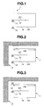
- Fig. 1 shows a front elevation view of the antenna related to a first preferred embodiment according to the present invention as viewed from an inside of a vehicle (automotive vehicle).
- the vehicular glass antenna in the first embodiment includes: a core wire side feed point 11 and an earth side feed point 12.
- Earth side feed point 12 is disposed at a lower position of core wire side feed point 11 with a blank space from core wire side feed point 11 provided.
- One end of a horizontal strip 131 constituting a core wire side antenna element 13 is connected to core wire side feed point 11 and horizontal strip 131 is extended toward a direction away from core wire side feed point 11.
- one end of a loop shaped strip 141 constituting an earth side antenna element 14 is connected to earth side feed point 12.
- the other end of loop shaped strip 141 is disposed to enclose horizontal strip 131 in a rectangular shape to provide an opening end.
- a tip (section) of loop shaped strip 141 is formed to be the opening end.
- Fig. 2 shows a front elevation view of the vehicular glass antenna related to the second embodiment according to the present invention as viewed from the inside of the vehicle.
- a difference point of the second embodiment from the first embodiment is that the opening end of loop shaped strip 141 is formed with a proximity section 14a to a body flange of the vehicle so that the opening end of loop shaped strip 141 comes close to an end edge 2 of the body flange and a capacitive coupling is formed between the vehicular antenna (loop shaped strip 141) and the body flange (end edge 2 of the body flange).
- proximity section 14a to the body flange is formed so that the desired sensitivity of the antenna at the desired frequency bandwidth can easily be obtained.
- Fig. 3 shows a front elevation view of the vehicular glass antenna related to a third preferred embodiment according to the present invention as viewed from the inside of the vehicle.
- the difference point of the vehicular glass antenna in the third embodiment from that of the second embodiment is that earth side feed point 12 is spaced apart from core wire side feed point 11 at an upper side of core wire side feed point 11, proximity section 14a to the body flange is formed at the other end section of loop shaped strip 141 to which earth side feed point 12 is connected and is close to end edge 2 of the body flange and the capacitive coupling is formed between proximity section 14a and end edge 2 of the body flange. Even in the above-described structure, by forming proximity section 14a to the body flange, the desired sensitivity can easily be obtained at the desired frequency bandwidth.
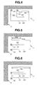
- Fig. 4 shows the vehicular glass antenna related to a fourth embodiment according to the present invention as viewed from the inside of the vehicle.
- the difference point of the vehicular antenna in the fourth embodiment from that of the second embodiment is that core wire side feed point 11 and earth side feed point 12 are laterally spaced apart from each other and core wire side antenna element 13 is constituted by letter L shaped strip, this letter L shaped strip being constituted by; a vertical strip 132 whose one end is connected to core wire side feed point 11 and which is extended toward a lower direction; and horizontal strip 131 which is connected to a lower end of vertical strip 132 and extended toward a rightward direction.
- the vehicular glass antenna even in the fourth embodiment, can easily obtain the desired sensitivity of the antenna at the desired frequency bandwidth even in such a structure as described above.
- Fig. 5 shows a front elevation view of the vehicular glass antenna related to a fifth preferred embodiment according to the present invention as viewed from the inside of the vehicle.
- the difference point of the vehicular antenna in the fifth embodiment from that in the second embodiment is that a tip section of loop shaped strip 141 is folded back toward an upper part of loop shaped strip 141 to form a folded back section 141a in the loop shaped strip, the tip section of folded back section 141a is placed in proximity of end edge 2 of the body flange to form proximity section 14a and the capacitive coupling is formed between proximity section 14a and end edge 2 of the body flange.
- the vehicular antenna in the fifth embodiment according to the present invention can, as described above, reduce an area enclosed by loop shaped strip 141 while maintaining a length of the loop shaped strip so as to obtain the desired sensitivity of the antenna at the desired frequency bandwidth by folding the tip section of loop shaped strip 141.
- the tip section of folded back section 141a of the loop shaped strip is placed in proximity of end edge 2 of the body flange of the vehicle to form proximity section 14a to the body flange so that the adjustment of the length of proximity section 14a to the body flange and the adjustment of an interval of proximity section 14a from end edge 2 of the body flange becomes facilitated. Consequently, the antenna tuning to obtain the desired sensitivity of the antenna at the desired frequency bandwidth can become easier.
- Fig. 6 shows a front elevation view of the vehicular antenna in a sixth preferred embodiment according to the present invention as viewed from the inside of the vehicle.
- core wire side antenna element 13 has two horizontal strips 131 whose one ends are connected to core wire side feed point 11 and extended in the same direction.
- the lengths of the two horizontal strips may have the same length or may be different from each other to obtain the desired sensitivity of the antenna at the desired frequency bandwidth.
- the positional relationship of their respective strips may not limited to the configuration of the fourth embodiment such that mutual ends of horizontal strip 131 and vertical strip 132 are connected together or to the configuration of the sixth embodiment such that the respective ends of the plurality of strips are connected to the core wire side feed point and extended in the same direction.
- the core wire side antenna element is constituted by the two strips
- one end of one of the two strips may be connected to core wire side feed point 11 and one end of the other of the two strips may be connected to a midway section of the one strip to which core wire side feed point 11 is connected.
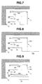
- Fig. 7 is a front elevation view of the vehicular glass antenna related to a seventh embodiment according to the present invention as viewed from the inside of the vehicle.
- the difference point of the vehicular antenna in the seventh embodiment from that in the second embodiment is that the shape of loop shaped strip 141 is not the rectangular.
- the vehicular glass antenna according to the present invention may not only the rectangular but at least core wire side strip 141 may be enclosed by loop shaped strip 141.
- the shape of loop shaped strip 141 does not matter.
- Fig. 8 shows a front elevation view of the vehicular glass antenna related to an eighth preferred embodiment according to the present invention as viewed from the inside of the vehicle.
- the difference point of the vehicular glass antenna in the eighth embodiment from that in the seventh embodiment is that one end of an auxiliary strip 142 as an auxiliary antenna element is connected to loop shaped strip 141.
- auxiliary strip 142 can serve to obtain the desired sensitivity of the antenna at the desired frequency bandwidth.
- Fig. 9 shows a front elevation view of the vehicular glass antenna related to a ninth preferred embodiment according to the present invention as viewed from the inside of the vehicle.
- the difference point of the vehicular glass antenna in the ninth embodiment from that in the eighth embodiment is that the auxiliary strip is a non-feed strip 15, non-feed strip 15 is placed in proximity of loop shaped strip 141, a proximity section 14b to this auxiliary antenna element is formed on loop shaped strip 141, and loop shaped strip 141 is placed in proximity of non-feed strip 15 at proximity section 14b to the non-feed strip and the capacitive coupling between loop shaped strip 141 and non-feed strip 15 is made. Even in a case where the auxiliary antenna element is constituted by non-feed strip 15, the auxiliary antenna element can help of obtaining the desired antenna sensitivity at the desired frequency bandwidth.
- Fig. 10 shows a front elevation view of the vehicular glass antenna related to a tenth preferred embodiment according to the present invention as viewed from the inside of the vehicle.
- the difference point of the vehicular glass antenna in the tenth embodiment from that in the eighth embodiment is that the tip section of loop shaped strip 141 is folded back and, as the auxiliary antenna element, in addition to auxiliary strip 142, an antenna element 32 constituting an FM (Frequency Modulation) second antenna is used.
- FM Frequency Modulation
- loop shaped strip 141 is placed in proximity of a part of the element of FM second antenna 32 and a proximity section 14c to the FM second antenna is formed and capacitive coupling between loop shaped strip 141 and FM second antenna is formed.
- a connection strip 133 to connect between upper horizontal strip 131 and lower horizontal strip 131 is disposed in core wire side antenna element 13. Even in a case where, as the auxiliary antenna element, the antenna element constituting another purpose antenna from the vehicular glass antenna is used, this auxiliary antenna element can help of obtaining the desired sensitivity of the antenna at the desired frequency bandwidth.
- a coaxial cable is used as a feeder line to transmit a signal received by the vehicular glass antenna to a receiver.
- a feed terminal is connected to a tip of the coaxial cable (not shown) and is soldered to core wire side feed point 11 of the vehicular glass antenna according to the present invention and to earth side feed point 12 according to the present invention.
- the core wire side of the feed terminal is connected to a core wire of the coaxial cable and a ground side of the feed terminal is connected to an outer sheath conductor of the coaxial cable.
- the vehicular glass antenna according to the present invention can use a generally available conductive ceramic paste which is the same as forming the defogger of the rear glass, can be printed in the same method as the defogger, and can be baked through a heat furnace.
- Vehicular glass antenna 1 in the tenth embodiment shown in Fig. 10 was disposed on a blank space section formed between an FM first antenna 4 at an upper part of defogger 6 of a rear glass 5 and an FM second antenna 3, as shown in Fig. 11 . Furthermore, a dimension and a positional relationship of each antenna constituent and a positional relationship thereof to FM second antenna 3 were adjusted for the vehicular glass antenna to be favorable in the frequency bandwidth of DAB band III of 174 through 240 MHz.
- rear glass 5 shown in Fig. 11 was attached onto the vehicle and a measurement of an antenna performance of vehicular antenna 1 in the tenth embodiment at the frequency bandwidth of band III of DAB in the tenth embodiment was carried out.
- Fig. 11 shows rear glass 5 as viewed from the inside of the vehicle.
- Defogger 6, FM first antenna 4, FM second antenna 3, and vehicular glass antenna 1 according to the present invention which was adjusted for receiving band III of DAB were disposed on rear glass 5.
- a pair of bus bars 62 were disposed on both ends of rear glass 5 along left and right ends of rear glass 5 and a plurality of heating strips 61 were disposed in a horizontal direction, and both ends of heating strips 61 were connected to bus bars 62, in the case of defogger 6.
- An orthogonal strip 63 was disposed from an uppermost heating strip 61 to a lowermost heating strip 61 along a center line d of leftward and rightward (horizontal) directions of rear glass 5. Orthogonal strip 63 was connected to all heating strips 61 which were overlapped on one another.
- FM first antenna 4 was disposed on an upper part of defogger 6 of rear glass 5.
- FM first antenna 4 has feed point 41 of FM first antenna disposed at the right side end section of rear glass 5 at the upper part of defogger 6.
- An antenna element 42 of FM first antenna was extended from feed point 41 of FM first antenna 4 so that a blank space section was formed at a left side of the upper part of defogger 6 of rear glass 5.
- FM second antenna 3 was disposed at a blank space section at the upper part of left side of defogger 6 of rear glass 5 in which no element 42 of FM first antenna was disposed.
- FM second antenna 3 has feed point 31 thereof disposed at a right side section of rear glass 5 at the upper part of defogger 6.
- Antenna element 32 of FM second antenna 3 was extended from feed point 31 of FM second antenna 3.
- antenna element 32 of FM second antenna 3 One end of a strip constituting antenna element 32 of FM second antenna 3 was connected to feed point 31 of FM second antenna 3, this strip being extended in the rightward direction of rear glass 5, being folded back at a middle point of the extended strip, and being formed as a folded back section 3c. Furthermore, antenna element 32 of FM second antenna 3 was constituted by double strips in which one strip was extended from feed point 31 of FM second antenna 3 toward folded back section 3c of the above-described strip so as to be parallel to the above-described strip.
- Vehicular glass antenna 1 was disposed at the blank space section on which antenna element 42 of FM first antenna 4 is not disposed at the left side of the upper part of defogger 6 of rear glass 5 and at the upper part of FM second antenna 3.
- core wire side feed point 11 and earth side feed point 12 were disposed so as to be spaced apart from each other in the vertical direction along a left side section of rear glass 5.
- Core wire side feed point 11 was disposed at a more upper part than earth side feed point 12.
- loop shaped strip 141 constituting earth side antenna element 14 was connected to earth side feed point 12 and a lower side of this strip 141 was extended toward the right side of rear glass 5.
- Loop shaped strip 141 is placed in proximity of folded back section 3c of the strip constituting antenna element 32 of FM second antenna 3 and a proximity section 14c between loop shaped strip 141 described above and FM second antenna 3 was formed and the capacitive coupling between proximity section 14c and FM second antenna 3 was carried out.
- auxiliary strip 142 of the earth side antenna element was connected to a bending point located at a lower part of loop shaped strip 141 and from which the loop shaped strip was folded back toward the upper direction and auxiliary strip 142 was extended in the horizontal (rightward) direction. Furthermore, folded back section 141a of loop shaped strip 141 was placed in the proximity of end edge 2 of the body flange when rear glass 5 was attached to the vehicle.
- a generally available conductive ceramic paste can be used for forming vehicular glass antenna 1 according to the present invention, FM second antenna 3, and FM first antenna 4 in the same way as the formation of the defogger of the rear glass of the vehicle.
- These antennae were printed in the same method as the defogger and baked by means of the heating furnace.
- a width of each strip constituting all of the antennae was 3mm.
- FM first antenna 4 was connected to an amplifier (not shown) installed on a vehicle body in proximity of feed point 41 of FM first antenna via an AV (Low-voltage cables for Automobile and Vinyl) cable and a coaxial cable extended from a receiver was connected to the amplifier. An outer sheath side of the coaxial cable is grounded to the vehicle body via the amplifier.
- FM second antenna 3 was not connected to the amplifier.
- a coaxial cable was connected from the receiver (not shown) to a ground point (not shown) placed on the vehicle body placed in proximity of feed point 31 of FM second antenna 31, the outer sheath side of the coaxial cable was grounded, a core wire side of the coaxial cable was connected to the AV cable (not shown) and was connected to feed point 31 of FM second antenna.
- the coaxial cable was used as the feed (or feeder) line to transmit the signal received by the antenna to the receiver in vehicular glass antenna 1.
- One tip of the coaxial cable was connected to a feed terminal (not shown) and an earth side of the feed terminal was connected to earth side feed point 12 and a hot side (core wire side) of the feed terminal was connected to a hot side (core wire side) feed point 11.
- the feed terminal and each feed point were soldered.
- the hot side of the feed terminal was connected to the core wire of the coaxial cable and the earth side of the feed terminal was connected to an outer sheath conductor of the coaxial cable. Then, the other tip of the coaxial cable was connected to the receiver.
- Fig.12 shows an average value of the antenna sensitivities in all directions at each of frequencies in the frequency bandwidth of 174 through 240MHz which is the band III of DAB in the vehicular glass antenna according to the present invention.
- a scale of a lateral axis of Fig. 12 is the frequency and a unit of each scale in the lateral axis is MHz.
- a longitudinal axis of Fig. 12 indicates the antenna sensitivities and one scale thereof corresponds to 10dB.
- Vehicular glass antenna 1 in the second embodiment was disposed on a left side upper part of front glass 7 as shown in Fig. 13 (viewed from the inside of the vehicle). The dimensions and positional relationship of the respective antenna elements and feed points were adjusted so that the sensitivities become favorable in the frequency bandwidth of 174 through 240 MHz of band III of DAB. Then, the measurement of the antenna performance of the vehicular glass antenna in the second embodiment in the frequency bandwidth of band III of DAB was carried out.
- the coaxial cable was used as the feed (or feeder) line to transmit the signal received by antenna 1 to the receiver.
- One tip of the coaxial cable was connected to the feed terminal (not shown), the earth side of the feed terminal being connected to earth side feed point 12 and the hot side (core wire side) of the feed terminal being connected to hot side (core wire side) feed point 11. Then, the feed terminal and the respective feed points are soldered (connected to each other by means of a soldering).
- the hot side (core wire side) of the feed terminal was connected to the core wire of the coaxial cable and the earth side of the feed terminal was connected to the outer sheath conductor of the coaxial cable. Then, the other tip of the coaxial cable was connected to the receiver. Then, as the result of measurement, it was appreciated that the uniform high sensitivities of the antenna were obtained in the frequency band of 174 through 240 MHz which is the band III of DAB in the same way as first example 1.
- Vehicular glass antenna 1 in the first embodiment according to the present invention was disposed at a left side section of a side glass 8 as shown in Fig. 14 .
- the coaxial cable was used as the feed line to transmit the signal received by the antenna to the receiver.
- One tip of the coaxial cable is connected to the feed terminal (not shown), the earth side of the feed terminal being connected to earth side feed point 12 and the hot side (core wire side) of the feed terminal being connected to hot side (core wire side) feed point 11.
- the feed terminal and respective feed points were soldered (connected to each other by means of soldering).
- the hot side of the feed terminal was connected to the core wire of the coaxial cable and the earth side of the feed terminal was connected to the outer sheath conductor of the coaxial cable.
- the other tip of the coaxial cable was connected to the receiver.
Landscapes
- Physics & Mathematics (AREA)
- Electromagnetism (AREA)
- Details Of Aerials (AREA)
- Support Of Aerials (AREA)
Abstract
Description
- The present invention relates to a vehicular glass antenna mounted on a window glass of an automotive (vehicle) and which is capable of receiving appropriately an electric wave of a terrestrial digital radio broadcasting, viz., DAB (DAB: Digital Audio Broadcasting).
- Recently, in a radio broadcasting, digital radios having various types of digital modulation systems of low noise and high quality as compared with those having conventional analog modulation systems have been developed. In each country of the world, digital radio broadcastings of various types of broadcasting standards have been put into practice. The various types of broadcasting standards include DAB (Digital Audio Broadcasting), DRM (Digital Radio Mondiale), DMB (Digital Multimedia Broadcasting), ISDB (Integrated Services Digital Broadcasting), and so forth.
- From among these various types of digital radio broadcasting standards, a standard which has almost been used in each country of the world is DAB standard. A first frequency bandwidth of DAB standard is a band III having a frequency bandwidth of 174 through 240MHz and a second frequency bandwidth of DAB standard is an L band of DAB standard having the frequency bandwidth of 1452 through 1492 MHz. These separate frequency bandwidths have been used.
- The frequency bandwidth of band III of DAB standard is wide. Hence, it is necessary for the vehicular glass antenna which receives this electric wave to be able to receive the electric wave with an equally high sensitivity at a desired wide frequency bandwidth. A Japanese Patent Application First Publication (tokkai) No.
2005-2291140 published on August 25, 2005 - In addition, another Japanese Patent Application First Publication (tokkai) No.
2012-029032 published on February 9, 2012 - The second antenna element in the first previously proposed vehicular glass antenna is structured in the closed loop shape. In a case where this vehicular glass antenna is applied to a window glass of the vehicle having various forms, large difficulties are involved in an antenna tuning of adjusting a length and a form of each antenna element to obtain a desired antenna sensitivity at a desired bandwidth.
- On the other hand, in the second previously proposed vehicular glass antenna, the respective tip sections of the earth side first element and the earth side second element are overlapped on each other so that their lengths and an interval of overlapped sections can be adjusted. Hence, as compared with the first previously proposed vehicular glass antenna, in a case where the second previously proposed vehicular glass antenna is applied to the window glass of the vehicle having various shapes, the adjustment to obtain the desired antenna sensitivity at the desired frequency bandwidth becomes facilitated. However, large difficulties are involved in finding an optimum antenna pattern when overlapped lengths of the respective tip sections of the earth side first antenna element and the earth side second antenna element and an arrangement of these respective antenna elements are adjusted.
- It is, therefore, an object of the present invention to provide a vehicular glass antenna which can solve the above-described problems, namely, which is capable of appropriately receiving the electric wave of band III of DAB over a whole frequency bandwidth of band III of DAB, whose antenna configuration is simple, and which is easy in adjustments to obtain a desired antenna sensitivity in band III of DAB when applied to various vehicular window glasses.
- According to the present invention, there is provided a vehicular glass antenna disposed on a window glass of an automotive vehicle, comprising: a core wire side feed point; an earth side feed point which is separate from the core wire side feed point; a core wire side antenna element connected to the core wire side feed point and extended in a direction far away from the core wire side feed point; and a loop shaped strip connected to the earth side feed point, the loop shaped strip being extended in the direction far away from the core wire side feed point and the earth side feed point and bent to enclose the core wire side antenna element and a tip section of the loop shaped strip providing an opening end.
- In the vehicular glass antenna according to the present invention, the tip section of the loop shaped strip provides the opening end, as described above. Thus, the antenna tuning of adjusting the length of the loop shaped strip and/or adjusting the shape of the loop shaped strip to obtain the desired antenna sensitivity at the desired frequency bandwidth becomes easy when the vehicular antenna according to the present invention is applied to various types of the vehicle.
- In addition, in the vehicular glass antenna according to the present invention, when the vehicular glass antenna according to the present invention is attached to a vehicle body, the vehicular glass antenna may be disposed on the window glass in order for a part of the loop shaped strip to be placed in the proximity of an end edge of a body flange of the vehicle body.
- In the vehicular glass antenna according to the present invention, a part of the loop shaped strip is placed in proximity of the end edge of the body flange to achieve a capacitive coupling between the loop shaped strip and the end edge of the body flange so that it becomes easy for the vehicular glass antenna according to the present invention to obtain the desired antenna sensitivity at the desired frequency bandwidth.
- Furthermore, in the vehicular glass antenna according to the present invention, the tip section of the loop shaped strip can be folded back.
- In the vehicular glass antenna according to the present invention, by folding the tip section of the loop shaped strip as described above, an area enclosed by the loop shaped strip can be made small while maintaining the length of the loop shaped strip in order to obtain the desired antenna sensitivity at the desired frequency bandwidth. In addition, in the vehicular glass antenna shown in
Fig. 5 , the tip section of the loop shaped strip folded back toward an upper side of the end edge of the body flange is placed in proximity of the end edge of the body flange so that adjustments of a length of the tip section of the loop shaped strip and an interval between the tip section and the upper side of the end edge of the body flange become easy. Hence, the antenna tuning of the vehicular glass antenna according to the present invention to obtain the desired antenna sensitivity at the desired frequency bandwidth becomes easier. - In addition, in the vehicular glass antenna according to the present invention, an auxiliary antenna element may be connected to the loop shaped strip or the auxiliary antenna element may be disposed so as to be placed in the proximity of the loop shaped strip at an outside of the loop shaped strip to achieve the capacitive coupling between the auxiliary antenna element and the loop shaped strip. By providing such an auxiliary antenna element as described above, an input impedance of the vehicular glass antenna according to the present invention is adjusted. Hence, the adjustment for obtaining the desired antenna sensitivity at the desired frequency bandwidth becomes easy.
- In the vehicular glass antenna according to the present invention, a whole length of the loop shaped antenna may be set to 0.7 α λ (α: a shortening coefficient of wavelength in a glass plate and λ : a center frequency in a desired frequency bandwidth). By setting the length of the loop shaped strip as described above, the desired antenna sensitivity at the desired bandwidth can be obtained.
- In the vehicular glass antenna according to the present invention, the tip section of the loop shaped strip provides the opening end. Hence, when the vehicular glass antenna is applied to various types of the vehicle, the antenna tuning of adjusting the length of the loop shaped strip and adjusting the shape of the loop shaped strip to obtain the desired antenna sensitivity at the desired frequency bandwidth can be facilitated.
-
-
Fig. 1 is a front elevation view of a vehicular glass antenna related to a first preferred embodiment as viewed from an inside of a vehicle. -
Fig. 2 is a front elevation view of the vehicular glass antenna related to a second preferred embodiment as viewed from the inside of the vehicle. -
Fig. 3 is a front elevation view of the vehicular glass antenna related to a third preferred embodiment as viewed from the inside of the vehicle. -
Fig. 4 is a front elevation view of the vehicular glass antenna related to a fourth preferred embodiment as viewed from the inside of the vehicle. -
Fig. 5 is a front elevation view of the vehicular glass antenna related to a fifth preferred embodiment as viewed from the inside of the vehicle. -
Fig. 6 is a front elevation view of the vehicular glass antenna related to a sixth preferred embodiment as viewed from the inside of the vehicle. -
Fig. 7 is a front elevation view of the vehicular glass antenna related to a seventh preferred embodiment as viewed from the inside of the vehicle. -
Fig. 8 is a front elevation view of the vehicular glass antenna related to an eighth preferred embodiment as viewed from the inside of the vehicle. -
Fig. 9 is a front elevation view of the vehicular glass antenna related to a ninth preferred embodiment as viewed from the inside of the vehicle. -
Fig. 10 is a front elevation view of the vehicular glass antenna related to a tenth preferred embodiment as viewed from the inside of the vehicle. -
Fig. 11 is a front elevation view of a whole rear glass as viewed from the inside of the vehicle when the vehicular glass antenna related to the tenth preferred embodiment is attached onto a (blank) space section of an upper part of a defogger of a rear glass of the vehicle. -
Fig. 12 is a graph representing a result of measurement of an antenna sensitivity in band III of DAB when the vehicular glass antenna related to the tenth embodiment is attached onto the blank space section of the upper part of the defogger of the rear glass. -
Fig. 13 is a front elevation view of a whole front glass as viewed from the inside of the vehicle when the vehicular glass antenna related to the second embodiment is attached to an upper side of a front glass of the vehicle. -
Fig. 14 is a front elevation view of a whole side glass as viewed from the inside of the vehicle when a vehicular glass antenna related to the first embodiment is attached to the side glass of the vehicle. - Hereinafter, a structure of the vehicular glass antenna of the preferred embodiments according to the present invention will be described. It should be noted that terms of upper and lower and left and right are used for the accompanied drawings and they are not prescribe a direction of actual products (articles).
-
Fig. 1 shows a front elevation view of the antenna related to a first preferred embodiment according to the present invention as viewed from an inside of a vehicle (automotive vehicle). - The vehicular glass antenna in the first embodiment includes: a core wire
side feed point 11 and an earthside feed point 12. Earthside feed point 12 is disposed at a lower position of core wireside feed point 11 with a blank space from core wireside feed point 11 provided. - One end of a
horizontal strip 131 constituting a core wireside antenna element 13 is connected to core wireside feed point 11 andhorizontal strip 131 is extended toward a direction away from core wireside feed point 11. In addition, one end of a loop shapedstrip 141 constituting an earthside antenna element 14 is connected to earthside feed point 12. The other end of loop shapedstrip 141 is disposed to enclosehorizontal strip 131 in a rectangular shape to provide an opening end. - In the vehicular glass antenna in the first embodiment is, as described above, a tip (section) of loop shaped
strip 141 is formed to be the opening end. Thus, an antenna tuning such that a length of loop shapedstrip 141 is adjusted or a shape thereof is adjusted can become facilitated to obtain a desired sensitivity at a desired frequency bandwidth when the vehicular antenna according to the present invention is applied to various types of vehicles. -
Fig. 2 shows a front elevation view of the vehicular glass antenna related to the second embodiment according to the present invention as viewed from the inside of the vehicle. A difference point of the second embodiment from the first embodiment is that the opening end of loop shapedstrip 141 is formed with aproximity section 14a to a body flange of the vehicle so that the opening end of loop shapedstrip 141 comes close to anend edge 2 of the body flange and a capacitive coupling is formed between the vehicular antenna (loop shaped strip 141) and the body flange (endedge 2 of the body flange). - As described above, in the vehicular antenna in the second embodiment,
proximity section 14a to the body flange is formed so that the desired sensitivity of the antenna at the desired frequency bandwidth can easily be obtained. -
Fig. 3 shows a front elevation view of the vehicular glass antenna related to a third preferred embodiment according to the present invention as viewed from the inside of the vehicle. - The difference point of the vehicular glass antenna in the third embodiment from that of the second embodiment is that earth
side feed point 12 is spaced apart from core wireside feed point 11 at an upper side of core wireside feed point 11,proximity section 14a to the body flange is formed at the other end section of loop shapedstrip 141 to which earthside feed point 12 is connected and is close to endedge 2 of the body flange and the capacitive coupling is formed betweenproximity section 14a and endedge 2 of the body flange. Even in the above-described structure, by formingproximity section 14a to the body flange, the desired sensitivity can easily be obtained at the desired frequency bandwidth. -
Fig. 4 shows the vehicular glass antenna related to a fourth embodiment according to the present invention as viewed from the inside of the vehicle. - The difference point of the vehicular antenna in the fourth embodiment from that of the second embodiment is that core wire
side feed point 11 and earthside feed point 12 are laterally spaced apart from each other and core wireside antenna element 13 is constituted by letter L shaped strip, this letter L shaped strip being constituted by; avertical strip 132 whose one end is connected to core wireside feed point 11 and which is extended toward a lower direction; andhorizontal strip 131 which is connected to a lower end ofvertical strip 132 and extended toward a rightward direction. The vehicular glass antenna, even in the fourth embodiment, can easily obtain the desired sensitivity of the antenna at the desired frequency bandwidth even in such a structure as described above. -
Fig. 5 shows a front elevation view of the vehicular glass antenna related to a fifth preferred embodiment according to the present invention as viewed from the inside of the vehicle. - The difference point of the vehicular antenna in the fifth embodiment from that in the second embodiment is that a tip section of loop shaped
strip 141 is folded back toward an upper part of loop shapedstrip 141 to form a folded backsection 141a in the loop shaped strip, the tip section of folded backsection 141a is placed in proximity ofend edge 2 of the body flange to formproximity section 14a and the capacitive coupling is formed betweenproximity section 14a and endedge 2 of the body flange. - The vehicular antenna in the fifth embodiment according to the present invention can, as described above, reduce an area enclosed by loop shaped
strip 141 while maintaining a length of the loop shaped strip so as to obtain the desired sensitivity of the antenna at the desired frequency bandwidth by folding the tip section of loop shapedstrip 141.
In addition, since the tip section of folded backsection 141a of the loop shaped strip is placed in proximity ofend edge 2 of the body flange of the vehicle toform proximity section 14a to the body flange so that the adjustment of the length ofproximity section 14a to the body flange and the adjustment of an interval ofproximity section 14a fromend edge 2 of the body flange becomes facilitated. Consequently, the antenna tuning to obtain the desired sensitivity of the antenna at the desired frequency bandwidth can become easier. -
Fig. 6 shows a front elevation view of the vehicular antenna in a sixth preferred embodiment according to the present invention as viewed from the inside of the vehicle. The difference of the vehicular antenna in the sixth embodiment from that in the second embodiment is that core wireside antenna element 13 has twohorizontal strips 131 whose one ends are connected to core wireside feed point 11 and extended in the same direction. The lengths of the two horizontal strips may have the same length or may be different from each other to obtain the desired sensitivity of the antenna at the desired frequency bandwidth. - In addition, in a case where core wire
side antenna element 13 is constituted by a plurality of strips, the positional relationship of their respective strips may not limited to the configuration of the fourth embodiment such that mutual ends ofhorizontal strip 131 andvertical strip 132 are connected together or to the configuration of the sixth embodiment such that the respective ends of the plurality of strips are connected to the core wire side feed point and extended in the same direction.
For example, in a case where the core wire side antenna element is constituted by the two strips, one end of one of the two strips may be connected to core wireside feed point 11 and one end of the other of the two strips may be connected to a midway section of the one strip to which core wireside feed point 11 is connected. -
Fig. 7 is a front elevation view of the vehicular glass antenna related to a seventh embodiment according to the present invention as viewed from the inside of the vehicle. - The difference point of the vehicular antenna in the seventh embodiment from that in the second embodiment is that the shape of loop shaped
strip 141 is not the rectangular. - The vehicular glass antenna according to the present invention may not only the rectangular but at least core
wire side strip 141 may be enclosed by loop shapedstrip 141. The shape of loop shapedstrip 141 does not matter. -
Fig. 8 shows a front elevation view of the vehicular glass antenna related to an eighth preferred embodiment according to the present invention as viewed from the inside of the vehicle. - The difference point of the vehicular glass antenna in the eighth embodiment from that in the seventh embodiment is that one end of an
auxiliary strip 142 as an auxiliary antenna element is connected to loop shapedstrip 141. In this way, by connectingauxiliary strip 142 to loop shapedstrip 141, an input impedance of the vehicular glass antenna according to the present invention can be adjusted to meet a characteristic impedance of a coaxial cable connected to the vehicular glass antenna according to the present invention. Thus,auxiliary strip 142 can serve to obtain the desired sensitivity of the antenna at the desired frequency bandwidth. -
Fig. 9 shows a front elevation view of the vehicular glass antenna related to a ninth preferred embodiment according to the present invention as viewed from the inside of the vehicle. - The difference point of the vehicular glass antenna in the ninth embodiment from that in the eighth embodiment is that the auxiliary strip is a
non-feed strip 15,non-feed strip 15 is placed in proximity of loop shapedstrip 141, aproximity section 14b to this auxiliary antenna element is formed on loop shapedstrip 141, and loop shapedstrip 141 is placed in proximity ofnon-feed strip 15 atproximity section 14b to the non-feed strip and the capacitive coupling between loop shapedstrip 141 andnon-feed strip 15 is made. Even in a case where the auxiliary antenna element is constituted bynon-feed strip 15, the auxiliary antenna element can help of obtaining the desired antenna sensitivity at the desired frequency bandwidth. -
Fig. 10 shows a front elevation view of the vehicular glass antenna related to a tenth preferred embodiment according to the present invention as viewed from the inside of the vehicle. - The difference point of the vehicular glass antenna in the tenth embodiment from that in the eighth embodiment is that the tip section of loop shaped
strip 141 is folded back and, as the auxiliary antenna element, in addition toauxiliary strip 142, anantenna element 32 constituting an FM (Frequency Modulation) second antenna is used. - In addition, loop shaped
strip 141 is placed in proximity of a part of the element of FMsecond antenna 32 and a proximity section 14c to the FM second antenna is formed and capacitive coupling between loop shapedstrip 141 and FM second antenna is formed. It should be noted that aconnection strip 133 to connect between upperhorizontal strip 131 and lowerhorizontal strip 131 is disposed in core wireside antenna element 13. Even in a case where, as the auxiliary antenna element, the antenna element constituting another purpose antenna from the vehicular glass antenna is used, this auxiliary antenna element can help of obtaining the desired sensitivity of the antenna at the desired frequency bandwidth. - In the vehicular glass antenna according to the present invention, a coaxial cable is used as a feeder line to transmit a signal received by the vehicular glass antenna to a receiver. A feed terminal is connected to a tip of the coaxial cable (not shown) and is soldered to core wire
side feed point 11 of the vehicular glass antenna according to the present invention and to earthside feed point 12 according to the present invention. The core wire side of the feed terminal is connected to a core wire of the coaxial cable and a ground side of the feed terminal is connected to an outer sheath conductor of the coaxial cable. - The vehicular glass antenna according to the present invention can use a generally available conductive ceramic paste which is the same as forming the defogger of the rear glass, can be printed in the same method as the defogger, and can be baked through a heat furnace.
-
Vehicular glass antenna 1 in the tenth embodiment shown inFig. 10 was disposed on a blank space section formed between an FMfirst antenna 4 at an upper part ofdefogger 6 of arear glass 5 and an FMsecond antenna 3, as shown inFig. 11 . Furthermore, a dimension and a positional relationship of each antenna constituent and a positional relationship thereof to FMsecond antenna 3 were adjusted for the vehicular glass antenna to be favorable in the frequency bandwidth of DAB band III of 174 through 240 MHz. - Then,
rear glass 5 shown inFig. 11 was attached onto the vehicle and a measurement of an antenna performance ofvehicular antenna 1 in the tenth embodiment at the frequency bandwidth of band III of DAB in the tenth embodiment was carried out. -
Fig. 11 showsrear glass 5 as viewed from the inside of the vehicle.Defogger 6, FMfirst antenna 4, FMsecond antenna 3, andvehicular glass antenna 1 according to the present invention which was adjusted for receiving band III of DAB were disposed onrear glass 5. - A pair of
bus bars 62 were disposed on both ends ofrear glass 5 along left and right ends ofrear glass 5 and a plurality of heating strips 61 were disposed in a horizontal direction, and both ends of heating strips 61 were connected tobus bars 62, in the case ofdefogger 6. Anorthogonal strip 63 was disposed from anuppermost heating strip 61 to alowermost heating strip 61 along a center line d of leftward and rightward (horizontal) directions ofrear glass 5.Orthogonal strip 63 was connected to all heating strips 61 which were overlapped on one another. - FM
first antenna 4 was disposed on an upper part ofdefogger 6 ofrear glass 5. FMfirst antenna 4 hasfeed point 41 of FM first antenna disposed at the right side end section ofrear glass 5 at the upper part ofdefogger 6. Anantenna element 42 of FM first antenna was extended fromfeed point 41 of FMfirst antenna 4 so that a blank space section was formed at a left side of the upper part ofdefogger 6 ofrear glass 5. - FM
second antenna 3 was disposed at a blank space section at the upper part of left side ofdefogger 6 ofrear glass 5 in which noelement 42 of FM first antenna was disposed. FMsecond antenna 3 hasfeed point 31 thereof disposed at a right side section ofrear glass 5 at the upper part ofdefogger 6.Antenna element 32 of FMsecond antenna 3 was extended fromfeed point 31 of FMsecond antenna 3. - One end of a strip constituting
antenna element 32 of FMsecond antenna 3 was connected to feedpoint 31 of FMsecond antenna 3, this strip being extended in the rightward direction ofrear glass 5, being folded back at a middle point of the extended strip, and being formed as a folded backsection 3c.
Furthermore,antenna element 32 of FMsecond antenna 3 was constituted by double strips in which one strip was extended fromfeed point 31 of FMsecond antenna 3 toward folded backsection 3c of the above-described strip so as to be parallel to the above-described strip. -
Vehicular glass antenna 1 according to the present invention was disposed at the blank space section on whichantenna element 42 of FMfirst antenna 4 is not disposed at the left side of the upper part ofdefogger 6 ofrear glass 5 and at the upper part of FMsecond antenna 3. - In
vehicular glass antenna 1 according to the present invention, core wireside feed point 11 and earthside feed point 12 were disposed so as to be spaced apart from each other in the vertical direction along a left side section ofrear glass 5. Core wireside feed point 11 was disposed at a more upper part than earthside feed point 12. - One end of loop shaped
strip 141 constituting earthside antenna element 14 was connected to earthside feed point 12 and a lower side of thisstrip 141 was extended toward the right side ofrear glass 5. Loop shapedstrip 141 is placed in proximity of folded backsection 3c of the strip constitutingantenna element 32 of FMsecond antenna 3 and a proximity section 14c between loop shapedstrip 141 described above and FMsecond antenna 3 was formed and the capacitive coupling between proximity section 14c and FMsecond antenna 3 was carried out.
In such a configuration as described above, in order for the lower part of loop shapedstrip 141 to be placed in the proximity of the folded back section (3c) of the strip constitutingantenna element 32 at a constant interval, the lower part of loop shaped strip extended from earthside feed point 12 was extended toward the rightward direction and, thereafter, once bent toward the lower side, and, thereafter, was folded back in the upper direction. - In addition, one end of
auxiliary strip 142 of the earth side antenna element was connected to a bending point located at a lower part of loop shapedstrip 141 and from which the loop shaped strip was folded back toward the upper direction andauxiliary strip 142 was extended in the horizontal (rightward) direction. Furthermore, folded backsection 141a of loop shapedstrip 141 was placed in the proximity ofend edge 2 of the body flange whenrear glass 5 was attached to the vehicle. - Dimensions are hereinbelow described using symbols shown in
Fig. 10 . -
- Dimensions of core wire side feed point and earth side feed point = 10mm x 10mm
- An
interval 1k between core wireside feed point 11 and earthside feed point 12 = 30mm - A
length 1a ofhorizontal strip 131 of core wire side antenna element = 110mm - An
interval 1b betweenhorizontal strips 131 of the two core wire side antenna elements = 15mm - A whole length of loop shaped
strip 141 = 670mm A length of apart 1c of loop shapedstrip 141 = 175mm - A length of a
part 1d of loop shapedstrip 141 = 40mm - A length of a
part 1e of loop shapedstrip 141 = 45mm - A length of a
part 1f of loop shapedstrip 141 = 115mm - A length of a
part 1g of loop shapedstrip 141 = 220mm - A whole length of folded back
section 141a of the loop shapedstrip 141a = 75mm - A length of a
part 1h of folded backsection 141a of the loop shaped strip = 15mm - A length of a
part 1i of folded backsection 141a of the loop shaped strip = 60mm - A length of
auxiliary strip 142 of the earth side element = 110mm - A length of
proximity section 14a between the loop shaped element and the end edge of the body flange = 60mm - A length of proximity section 14c between the loop shaped element and the FM
second antenna 3 = 205mm - A whole length of loop shaped
strip 141 can be expressed as about 0.7 α λ when a wavelength of a center frequency (207MHz) of the frequency bandwidth of band III of DAB is λ and a shortening coefficient α of wavelength of a glass (plate) on which the vehicular glass antenna according to the present invention is disposed is α =0.7. -
- A length of a
part 3a of FM second antenna = 170mm - A length of a
part 3b of FM second antenna = 25mm - A length of a
part 3c of FM second antenna = 160mm - A length of a
part 3d of FM second antenna = 10mm -
- An interval a between
end edge 2 of the flange and folded backsection 14a = 5mm - An interval b between a lower horizontal section of loop shaped
strip 141 and folded backsection 3c of FMsecond antenna 3 = 5mm - An interval c between a bending section of loop shaped
strip 141 toward the lower section lower side and folded backsection 3c of FMsecond antenna 3= 5mm - An interval d between earth
side feed point 12 andfeed point 31 of FMsecond antenna 3 = 20mm - A generally available conductive ceramic paste can be used for forming
vehicular glass antenna 1 according to the present invention, FMsecond antenna 3, and FMfirst antenna 4 in the same way as the formation of the defogger of the rear glass of the vehicle. These antennae were printed in the same method as the defogger and baked by means of the heating furnace. In addition, a width of each strip constituting all of the antennae was 3mm. - FM
first antenna 4 was connected to an amplifier (not shown) installed on a vehicle body in proximity offeed point 41 of FM first antenna via an AV (Low-voltage cables for Automobile and Vinyl) cable and a coaxial cable extended from a receiver was connected to the amplifier. An outer sheath side of the coaxial cable is grounded to the vehicle body via the amplifier. In addition, FMsecond antenna 3 was not connected to the amplifier. Therefore, for FMsecond antenna 3, a coaxial cable was connected from the receiver (not shown) to a ground point (not shown) placed on the vehicle body placed in proximity offeed point 31 of FMsecond antenna 31, the outer sheath side of the coaxial cable was grounded, a core wire side of the coaxial cable was connected to the AV cable (not shown) and was connected to feedpoint 31 of FM second antenna. - The coaxial cable was used as the feed (or feeder) line to transmit the signal received by the antenna to the receiver in
vehicular glass antenna 1. One tip of the coaxial cable was connected to a feed terminal (not shown) and an earth side of the feed terminal was connected to earthside feed point 12 and a hot side (core wire side) of the feed terminal was connected to a hot side (core wire side)feed point 11. - The feed terminal and each feed point were soldered.
- In addition, the hot side of the feed terminal was connected to the core wire of the coaxial cable and the earth side of the feed terminal was connected to an outer sheath conductor of the coaxial cable. Then, the other tip of the coaxial cable was connected to the receiver.
-
Fig.12 shows an average value of the antenna sensitivities in all directions at each of frequencies in the frequency bandwidth of 174 through 240MHz which is the band III of DAB in the vehicular glass antenna according to the present invention. - A scale of a lateral axis of
Fig. 12 is the frequency and a unit of each scale in the lateral axis is MHz. A longitudinal axis ofFig. 12 indicates the antenna sensitivities and one scale thereof corresponds to 10dB. - As shown in
Fig. 12 , it was appreciated that uniform high antenna sensitivities were obtained over the frequency bandwidth of 174 through 240 MHz which are band III of DAB. -
Vehicular glass antenna 1 in the second embodiment was disposed on a left side upper part offront glass 7 as shown inFig. 13 (viewed from the inside of the vehicle). The dimensions and positional relationship of the respective antenna elements and feed points were adjusted so that the sensitivities become favorable in the frequency bandwidth of 174 through 240 MHz of band III of DAB. Then, the measurement of the antenna performance of the vehicular glass antenna in the second embodiment in the frequency bandwidth of band III of DAB was carried out. - For
vehicular antenna 1 according to the present invention, the coaxial cable was used as the feed (or feeder) line to transmit the signal received byantenna 1 to the receiver. One tip of the coaxial cable was connected to the feed terminal (not shown), the earth side of the feed terminal being connected to earthside feed point 12 and the hot side (core wire side) of the feed terminal being connected to hot side (core wire side)feed point 11. Then, the feed terminal and the respective feed points are soldered (connected to each other by means of a soldering). - The hot side (core wire side) of the feed terminal was connected to the core wire of the coaxial cable and the earth side of the feed terminal was connected to the outer sheath conductor of the coaxial cable. Then, the other tip of the coaxial cable was connected to the receiver. Then, as the result of measurement, it was appreciated that the uniform high sensitivities of the antenna were obtained in the frequency band of 174 through 240 MHz which is the band III of DAB in the same way as first example 1.
-
Vehicular glass antenna 1 in the first embodiment according to the present invention was disposed at a left side section of aside glass 8 as shown inFig. 14 . - The dimensions and positional relationships were adjusted so that the antenna sensitivities were favorable in 174 through 240 MHz which is the frequency bandwidth of band III of DAB. Then, with
side glass 8 attached to the vehicle, the measurement of the antennal performance in the frequency bandwidth of band III of DAB was carried out. - For
vehicular glass antenna 1 according to the present invention, the coaxial cable was used as the feed line to transmit the signal received by the antenna to the receiver. - One tip of the coaxial cable is connected to the feed terminal (not shown), the earth side of the feed terminal being connected to earth
side feed point 12 and the hot side (core wire side) of the feed terminal being connected to hot side (core wire side)feed point 11. - Then, the feed terminal and respective feed points were soldered (connected to each other by means of soldering). The hot side of the feed terminal was connected to the core wire of the coaxial cable and the earth side of the feed terminal was connected to the outer sheath conductor of the coaxial cable. The other tip of the coaxial cable was connected to the receiver.
- Then, as the result of measurement, it was appreciated that the uniform high sensitivities of the antenna were obtained at the frequency bandwidth of 174 through 240 MHz which is band III of DAB in the same way as example 1.
Claims (11)
- A vehicular glass antenna disposed on a window glass of an automotive vehicle, comprising:a core wire side feed point (11);an earth side feed point (12) which is separate from the core wire side feed point (11);a core wire side antenna element (13) connected to the core wire side feed point (11) and extended in a direction far away from the core wire side feed point (11); anda loop shaped strip (141) connected to the earth side feed point (12), the loop shaped strip (141) being extended in the direction far away from the core wire side feed point (11) and the earth side feed point (12) and bent to enclose the core wire side antenna element (13) and a tip section of the loop shaped strip (141) providing an opening end.
- The vehicular glass antenna as claimed in claim 1, wherein the loop shaped strip (141) is placed in the proximity of an end edge (2) of a body flange of a vehicle body when the vehicular glass antenna is attached to the vehicle body.
- The vehicular glass antenna as claimed in either claim 1 or 2, wherein the tip section of the loop shaped strip (141) is folded back.
- The vehicular glass antenna as claimed in any one of the preceding claims 1 through 3, wherein an auxiliary antenna element (142) is connected to the loop shaped strip (141).
- The vehicular glass antenna as claimed in any one of the preceding claims 1 through 3, wherein an auxiliary antenna element (15, 32) is placed in the proximity of the loop shaped strip (141) at an outside of the loop shaped strip (141).
- The vehicular glass antenna as claimed in any one of the preceding claims 1 through 5, wherein a whole length of the loop shaped strip is set to 0.7 α λ (α : a shortening coefficient of wavelength in a glass plate and λ : a center frequency in a desired frequency bandwidth).
- The vehicular glass antenna as claimed in any one of the preceding claims 1 through 6, wherein the core wire side antenna element (13) is constituted by a horizontal strip (131) and the loop shaped strip (141) constitutes an earth side antenna element (14), one end of the loop shaped strip (141) being connected to the earth side feed point (12) and the other end of the loop shaped strip (141) being disposed in a rectangular shape to enclose the horizontal strip (131) to provide the opening end.
- The vehicular glass antenna as claimed in any one of the preceding claims 1 through 7, wherein the opening end of the loop shaped strip (141) forms a proximity section (14a) to the end edge (2) of the body flange.
- The vehicular glass antenna as claimed in any one of the preceding claims 1 through 8, wherein the core wire side antenna element (13) is constituted by two horizontal strips (131), one end of each of the horizontal strips (131) being connected to the core wire side feed point (11) and the horizontal strips (131) being extended in the same direction.
- The vehicular glass antenna as claimed in any one of the preceding claims 1 through 9, wherein one end of an auxiliary strip (142) is connected to the loop shaped strip (141) and the other end of the auxiliary strip (142) provides another opening end.
- The vehicular glass antenna as claimed in any one of the preceding claims 1 through 10, wherein an auxiliary antenna element constituted by a non-feed strip (15) is placed in the proximity of the loop shaped strip (141) or in addition to the auxiliary strip (142), another antenna element (32) constituting the auxiliary antenna element is placed in the proximity of the loop shaped strip at an outside of the loop shaped strip (141).
Applications Claiming Priority (1)
| Application Number | Priority Date | Filing Date | Title |
|---|---|---|---|
| JP2013076981A JP6094334B2 (en) | 2013-04-02 | 2013-04-02 | Glass antenna for vehicles |
Publications (2)
| Publication Number | Publication Date |
|---|---|
| EP2787573A1 true EP2787573A1 (en) | 2014-10-08 |
| EP2787573B1 EP2787573B1 (en) | 2016-11-30 |
Family
ID=50389247
Family Applications (1)
| Application Number | Title | Priority Date | Filing Date |
|---|---|---|---|
| EP14161055.0A Not-in-force EP2787573B1 (en) | 2013-04-02 | 2014-03-21 | Vehicular glass antenna |
Country Status (3)
| Country | Link |
|---|---|
| EP (1) | EP2787573B1 (en) |
| JP (1) | JP6094334B2 (en) |
| AU (1) | AU2014201814B2 (en) |
Cited By (8)
| Publication number | Priority date | Publication date | Assignee | Title |
|---|---|---|---|---|
| EP3032639A1 (en) * | 2014-12-08 | 2016-06-15 | Nippon Sheet Glass Co.,Ltd. | Vehicular glass antenna |
| EP3361562A1 (en) * | 2017-02-14 | 2018-08-15 | Asahi Glass Company, Limited | Glass antenna and window glass for vehicle |
| EP3361563A1 (en) * | 2017-02-14 | 2018-08-15 | Asahi Glass Company, Limited | Glass antenna and window glass for vehicle |
| CN108428996A (en) * | 2017-02-14 | 2018-08-21 | 旭硝子株式会社 | Window glass for vehicle |
| JP2018133798A (en) * | 2017-02-14 | 2018-08-23 | Agc株式会社 | Glass antenna and vehicle window glass |
| JP2021175045A (en) * | 2020-04-22 | 2021-11-01 | Agc株式会社 | Vehicle window glass |
| CN115566419A (en) * | 2017-03-29 | 2023-01-03 | 株式会社友华 | Antenna device |
| JP2023110634A (en) * | 2022-01-28 | 2023-08-09 | Agc株式会社 | vehicle window glass |
Families Citing this family (2)
| Publication number | Priority date | Publication date | Assignee | Title |
|---|---|---|---|---|
| JP6888423B2 (en) * | 2017-05-30 | 2021-06-16 | Agc株式会社 | Window glass with antenna |
| JP7743802B2 (en) | 2022-03-01 | 2025-09-25 | Agc株式会社 | Vehicle window glass |
Citations (4)
| Publication number | Priority date | Publication date | Assignee | Title |
|---|---|---|---|---|
| JP2005229140A (en) | 2003-03-19 | 2005-08-25 | Central Glass Co Ltd | Antenna for vehicle |
| JP2012023707A (en) * | 2010-06-16 | 2012-02-02 | Central Glass Co Ltd | Glass antenna for vehicle |
| JP2012029032A (en) | 2010-07-23 | 2012-02-09 | Central Glass Co Ltd | Vehicle antenna |
| WO2013094470A1 (en) * | 2011-12-21 | 2013-06-27 | セントラル硝子株式会社 | Vehicular glass antenna |
Family Cites Families (1)
| Publication number | Priority date | Publication date | Assignee | Title |
|---|---|---|---|---|
| JP3565406B2 (en) * | 1998-11-16 | 2004-09-15 | セントラル硝子株式会社 | Glass antenna for vehicles |
-
2013
- 2013-04-02 JP JP2013076981A patent/JP6094334B2/en active Active
-
2014
- 2014-03-21 EP EP14161055.0A patent/EP2787573B1/en not_active Not-in-force
- 2014-03-27 AU AU2014201814A patent/AU2014201814B2/en not_active Ceased
Patent Citations (4)
| Publication number | Priority date | Publication date | Assignee | Title |
|---|---|---|---|---|
| JP2005229140A (en) | 2003-03-19 | 2005-08-25 | Central Glass Co Ltd | Antenna for vehicle |
| JP2012023707A (en) * | 2010-06-16 | 2012-02-02 | Central Glass Co Ltd | Glass antenna for vehicle |
| JP2012029032A (en) | 2010-07-23 | 2012-02-09 | Central Glass Co Ltd | Vehicle antenna |
| WO2013094470A1 (en) * | 2011-12-21 | 2013-06-27 | セントラル硝子株式会社 | Vehicular glass antenna |
Cited By (13)
| Publication number | Priority date | Publication date | Assignee | Title |
|---|---|---|---|---|
| EP3032639A1 (en) * | 2014-12-08 | 2016-06-15 | Nippon Sheet Glass Co.,Ltd. | Vehicular glass antenna |
| CN108448224A (en) * | 2017-02-14 | 2018-08-24 | 旭硝子株式会社 | Glass antenna and window glass for vehicle |
| EP3361563A1 (en) * | 2017-02-14 | 2018-08-15 | Asahi Glass Company, Limited | Glass antenna and window glass for vehicle |
| CN108428996A (en) * | 2017-02-14 | 2018-08-21 | 旭硝子株式会社 | Window glass for vehicle |
| JP2018133798A (en) * | 2017-02-14 | 2018-08-23 | Agc株式会社 | Glass antenna and vehicle window glass |
| CN108448223A (en) * | 2017-02-14 | 2018-08-24 | 旭硝子株式会社 | Glass antenna and window glass for vehicle |
| EP3361562A1 (en) * | 2017-02-14 | 2018-08-15 | Asahi Glass Company, Limited | Glass antenna and window glass for vehicle |
| US10651537B2 (en) | 2017-02-14 | 2020-05-12 | AGC Inc. | Glass antenna and window glass for vehicle |
| CN108448223B (en) * | 2017-02-14 | 2020-11-27 | Agc株式会社 | Glass antenna and vehicle window glass |
| CN108448224B (en) * | 2017-02-14 | 2020-12-01 | Agc株式会社 | Glass antenna and vehicle window glass |
| CN115566419A (en) * | 2017-03-29 | 2023-01-03 | 株式会社友华 | Antenna device |
| JP2021175045A (en) * | 2020-04-22 | 2021-11-01 | Agc株式会社 | Vehicle window glass |
| JP2023110634A (en) * | 2022-01-28 | 2023-08-09 | Agc株式会社 | vehicle window glass |
Also Published As
| Publication number | Publication date |
|---|---|
| JP2014204190A (en) | 2014-10-27 |
| AU2014201814A1 (en) | 2014-10-16 |
| EP2787573B1 (en) | 2016-11-30 |
| AU2014201814B2 (en) | 2015-05-21 |
| JP6094334B2 (en) | 2017-03-15 |
Similar Documents
| Publication | Publication Date | Title |
|---|---|---|
| EP2787573B1 (en) | Vehicular glass antenna | |
| US8217845B2 (en) | High frequency glass antenna for automobiles | |
| EP3101733B1 (en) | Glass antenna | |
| US9136583B2 (en) | Automotive window antenna | |
| JP6390666B2 (en) | Glass antenna | |
| KR20070113128A (en) | Automotive High Frequency Glass Antenna | |
| JP4941171B2 (en) | Glass antenna for vehicles | |
| EP2797164B1 (en) | Automotive glass antenna | |
| EP3101734B1 (en) | Glass antenna | |
| JP6251476B2 (en) | Glass antenna for vehicles | |
| WO2013002134A1 (en) | Glass antenna for vehicle | |
| EP2924803B1 (en) | Vehicular glass antenna | |
| JP2016058946A (en) | Glass antenna for automobile | |
| JP6319407B2 (en) | Glass antenna for vehicles | |
| JP2023547508A (en) | glass antenna for vehicle | |
| JP2016072910A (en) | Antenna and window pane | |
| JP2003101318A (en) | Automotive window glass antenna | |
| CN101090171B (en) | High frequency wave glass antenna for an automobile | |
| EA046992B1 (en) | VEHICLE GLASS ANTENNA | |
| JP2007150966A (en) | High frequency glass antenna for automobile |
Legal Events
| Date | Code | Title | Description |
|---|---|---|---|
| PUAI | Public reference made under article 153(3) epc to a published international application that has entered the european phase |
Free format text: ORIGINAL CODE: 0009012 |
|
| 17P | Request for examination filed |
Effective date: 20140321 |
|
| AK | Designated contracting states |
Kind code of ref document: A1 Designated state(s): AL AT BE BG CH CY CZ DE DK EE ES FI FR GB GR HR HU IE IS IT LI LT LU LV MC MK MT NL NO PL PT RO RS SE SI SK SM TR |
|
| AX | Request for extension of the european patent |
Extension state: BA ME |
|
| R17P | Request for examination filed (corrected) |
Effective date: 20150326 |
|
| RBV | Designated contracting states (corrected) |
Designated state(s): AL AT BE BG CH CY CZ DE DK EE ES FI FR GB GR HR HU IE IS IT LI LT LU LV MC MK MT NL NO PL PT RO RS SE SI SK SM TR |
|
| 17Q | First examination report despatched |
Effective date: 20150923 |
|
| REG | Reference to a national code |
Ref country code: DE Ref legal event code: R079 Ref document number: 602014005118 Country of ref document: DE Free format text: PREVIOUS MAIN CLASS: H01Q0001120000 Ipc: H01Q0009420000 |
|
| GRAP | Despatch of communication of intention to grant a patent |
Free format text: ORIGINAL CODE: EPIDOSNIGR1 |
|
| RIC1 | Information provided on ipc code assigned before grant |
Ipc: H01Q 9/42 20060101AFI20160531BHEP Ipc: H01Q 5/40 20150101ALI20160531BHEP |
|
| INTG | Intention to grant announced |
Effective date: 20160617 |
|
| GRAS | Grant fee paid |
Free format text: ORIGINAL CODE: EPIDOSNIGR3 |
|
| GRAA | (expected) grant |
Free format text: ORIGINAL CODE: 0009210 |
|
| AK | Designated contracting states |
Kind code of ref document: B1 Designated state(s): AL AT BE BG CH CY CZ DE DK EE ES FI FR GB GR HR HU IE IS IT LI LT LU LV MC MK MT NL NO PL PT RO RS SE SI SK SM TR |
|
| REG | Reference to a national code |
Ref country code: CH Ref legal event code: EP Ref country code: GB Ref legal event code: FG4D |
|
| REG | Reference to a national code |
Ref country code: AT Ref legal event code: REF Ref document number: 850597 Country of ref document: AT Kind code of ref document: T Effective date: 20161215 |
|
| REG | Reference to a national code |
Ref country code: IE Ref legal event code: FG4D |
|
| REG | Reference to a national code |
Ref country code: DE Ref legal event code: R096 Ref document number: 602014005118 Country of ref document: DE |
|
| PG25 | Lapsed in a contracting state [announced via postgrant information from national office to epo] |
Ref country code: LV Free format text: LAPSE BECAUSE OF FAILURE TO SUBMIT A TRANSLATION OF THE DESCRIPTION OR TO PAY THE FEE WITHIN THE PRESCRIBED TIME-LIMIT Effective date: 20161130 |
|
| REG | Reference to a national code |
Ref country code: FR Ref legal event code: PLFP Year of fee payment: 4 |
|
| REG | Reference to a national code |
Ref country code: LT Ref legal event code: MG4D |
|
| REG | Reference to a national code |
Ref country code: NL Ref legal event code: MP Effective date: 20161130 |
|
| REG | Reference to a national code |
Ref country code: AT Ref legal event code: MK05 Ref document number: 850597 Country of ref document: AT Kind code of ref document: T Effective date: 20161130 |
|
| PG25 | Lapsed in a contracting state [announced via postgrant information from national office to epo] |
Ref country code: NO Free format text: LAPSE BECAUSE OF FAILURE TO SUBMIT A TRANSLATION OF THE DESCRIPTION OR TO PAY THE FEE WITHIN THE PRESCRIBED TIME-LIMIT Effective date: 20170228 Ref country code: LT Free format text: LAPSE BECAUSE OF FAILURE TO SUBMIT A TRANSLATION OF THE DESCRIPTION OR TO PAY THE FEE WITHIN THE PRESCRIBED TIME-LIMIT Effective date: 20161130 Ref country code: SE Free format text: LAPSE BECAUSE OF FAILURE TO SUBMIT A TRANSLATION OF THE DESCRIPTION OR TO PAY THE FEE WITHIN THE PRESCRIBED TIME-LIMIT Effective date: 20161130 Ref country code: GR Free format text: LAPSE BECAUSE OF FAILURE TO SUBMIT A TRANSLATION OF THE DESCRIPTION OR TO PAY THE FEE WITHIN THE PRESCRIBED TIME-LIMIT Effective date: 20170301 |
|
| PG25 | Lapsed in a contracting state [announced via postgrant information from national office to epo] |
Ref country code: HR Free format text: LAPSE BECAUSE OF FAILURE TO SUBMIT A TRANSLATION OF THE DESCRIPTION OR TO PAY THE FEE WITHIN THE PRESCRIBED TIME-LIMIT Effective date: 20161130 Ref country code: FI Free format text: LAPSE BECAUSE OF FAILURE TO SUBMIT A TRANSLATION OF THE DESCRIPTION OR TO PAY THE FEE WITHIN THE PRESCRIBED TIME-LIMIT Effective date: 20161130 Ref country code: ES Free format text: LAPSE BECAUSE OF FAILURE TO SUBMIT A TRANSLATION OF THE DESCRIPTION OR TO PAY THE FEE WITHIN THE PRESCRIBED TIME-LIMIT Effective date: 20161130 Ref country code: AT Free format text: LAPSE BECAUSE OF FAILURE TO SUBMIT A TRANSLATION OF THE DESCRIPTION OR TO PAY THE FEE WITHIN THE PRESCRIBED TIME-LIMIT Effective date: 20161130 Ref country code: PT Free format text: LAPSE BECAUSE OF FAILURE TO SUBMIT A TRANSLATION OF THE DESCRIPTION OR TO PAY THE FEE WITHIN THE PRESCRIBED TIME-LIMIT Effective date: 20170330 Ref country code: PL Free format text: LAPSE BECAUSE OF FAILURE TO SUBMIT A TRANSLATION OF THE DESCRIPTION OR TO PAY THE FEE WITHIN THE PRESCRIBED TIME-LIMIT Effective date: 20161130 Ref country code: RS Free format text: LAPSE BECAUSE OF FAILURE TO SUBMIT A TRANSLATION OF THE DESCRIPTION OR TO PAY THE FEE WITHIN THE PRESCRIBED TIME-LIMIT Effective date: 20161130 |
|
| PG25 | Lapsed in a contracting state [announced via postgrant information from national office to epo] |
Ref country code: NL Free format text: LAPSE BECAUSE OF FAILURE TO SUBMIT A TRANSLATION OF THE DESCRIPTION OR TO PAY THE FEE WITHIN THE PRESCRIBED TIME-LIMIT Effective date: 20161130 |
|
| PG25 | Lapsed in a contracting state [announced via postgrant information from national office to epo] |
Ref country code: DK Free format text: LAPSE BECAUSE OF FAILURE TO SUBMIT A TRANSLATION OF THE DESCRIPTION OR TO PAY THE FEE WITHIN THE PRESCRIBED TIME-LIMIT Effective date: 20161130 Ref country code: RO Free format text: LAPSE BECAUSE OF FAILURE TO SUBMIT A TRANSLATION OF THE DESCRIPTION OR TO PAY THE FEE WITHIN THE PRESCRIBED TIME-LIMIT Effective date: 20161130 Ref country code: CZ Free format text: LAPSE BECAUSE OF FAILURE TO SUBMIT A TRANSLATION OF THE DESCRIPTION OR TO PAY THE FEE WITHIN THE PRESCRIBED TIME-LIMIT Effective date: 20161130 Ref country code: EE Free format text: LAPSE BECAUSE OF FAILURE TO SUBMIT A TRANSLATION OF THE DESCRIPTION OR TO PAY THE FEE WITHIN THE PRESCRIBED TIME-LIMIT Effective date: 20161130 Ref country code: SK Free format text: LAPSE BECAUSE OF FAILURE TO SUBMIT A TRANSLATION OF THE DESCRIPTION OR TO PAY THE FEE WITHIN THE PRESCRIBED TIME-LIMIT Effective date: 20161130 |
|
| PG25 | Lapsed in a contracting state [announced via postgrant information from national office to epo] |
Ref country code: BG Free format text: LAPSE BECAUSE OF FAILURE TO SUBMIT A TRANSLATION OF THE DESCRIPTION OR TO PAY THE FEE WITHIN THE PRESCRIBED TIME-LIMIT Effective date: 20170228 Ref country code: BE Free format text: LAPSE BECAUSE OF FAILURE TO SUBMIT A TRANSLATION OF THE DESCRIPTION OR TO PAY THE FEE WITHIN THE PRESCRIBED TIME-LIMIT Effective date: 20161130 Ref country code: SM Free format text: LAPSE BECAUSE OF FAILURE TO SUBMIT A TRANSLATION OF THE DESCRIPTION OR TO PAY THE FEE WITHIN THE PRESCRIBED TIME-LIMIT Effective date: 20161130 Ref country code: IT Free format text: LAPSE BECAUSE OF FAILURE TO SUBMIT A TRANSLATION OF THE DESCRIPTION OR TO PAY THE FEE WITHIN THE PRESCRIBED TIME-LIMIT Effective date: 20161130 |
|
| REG | Reference to a national code |
Ref country code: DE Ref legal event code: R097 Ref document number: 602014005118 Country of ref document: DE |
|
| PLBE | No opposition filed within time limit |
Free format text: ORIGINAL CODE: 0009261 |
|
| STAA | Information on the status of an ep patent application or granted ep patent |
Free format text: STATUS: NO OPPOSITION FILED WITHIN TIME LIMIT |
|
| REG | Reference to a national code |
Ref country code: CH Ref legal event code: PL |
|
| 26N | No opposition filed |
Effective date: 20170831 |
|
| PG25 | Lapsed in a contracting state [announced via postgrant information from national office to epo] |
Ref country code: MC Free format text: LAPSE BECAUSE OF FAILURE TO SUBMIT A TRANSLATION OF THE DESCRIPTION OR TO PAY THE FEE WITHIN THE PRESCRIBED TIME-LIMIT Effective date: 20161130 Ref country code: SI Free format text: LAPSE BECAUSE OF FAILURE TO SUBMIT A TRANSLATION OF THE DESCRIPTION OR TO PAY THE FEE WITHIN THE PRESCRIBED TIME-LIMIT Effective date: 20161130 |
|
| REG | Reference to a national code |
Ref country code: IE Ref legal event code: MM4A |
|
| PG25 | Lapsed in a contracting state [announced via postgrant information from national office to epo] |
Ref country code: LU Free format text: LAPSE BECAUSE OF NON-PAYMENT OF DUE FEES Effective date: 20170321 |
|
| REG | Reference to a national code |
Ref country code: FR Ref legal event code: PLFP Year of fee payment: 5 |
|
| PG25 | Lapsed in a contracting state [announced via postgrant information from national office to epo] |
Ref country code: IE Free format text: LAPSE BECAUSE OF NON-PAYMENT OF DUE FEES Effective date: 20170321 Ref country code: CH Free format text: LAPSE BECAUSE OF NON-PAYMENT OF DUE FEES Effective date: 20170331 Ref country code: LI Free format text: LAPSE BECAUSE OF NON-PAYMENT OF DUE FEES Effective date: 20170331 |
|
| PG25 | Lapsed in a contracting state [announced via postgrant information from national office to epo] |
Ref country code: MT Free format text: LAPSE BECAUSE OF NON-PAYMENT OF DUE FEES Effective date: 20170321 |
|
| PG25 | Lapsed in a contracting state [announced via postgrant information from national office to epo] |
Ref country code: HU Free format text: LAPSE BECAUSE OF FAILURE TO SUBMIT A TRANSLATION OF THE DESCRIPTION OR TO PAY THE FEE WITHIN THE PRESCRIBED TIME-LIMIT; INVALID AB INITIO Effective date: 20140321 |
|
| PG25 | Lapsed in a contracting state [announced via postgrant information from national office to epo] |
Ref country code: CY Free format text: LAPSE BECAUSE OF FAILURE TO SUBMIT A TRANSLATION OF THE DESCRIPTION OR TO PAY THE FEE WITHIN THE PRESCRIBED TIME-LIMIT Effective date: 20161130 |
|
| PG25 | Lapsed in a contracting state [announced via postgrant information from national office to epo] |
Ref country code: MK Free format text: LAPSE BECAUSE OF FAILURE TO SUBMIT A TRANSLATION OF THE DESCRIPTION OR TO PAY THE FEE WITHIN THE PRESCRIBED TIME-LIMIT Effective date: 20161130 |
|
| PG25 | Lapsed in a contracting state [announced via postgrant information from national office to epo] |
Ref country code: TR Free format text: LAPSE BECAUSE OF FAILURE TO SUBMIT A TRANSLATION OF THE DESCRIPTION OR TO PAY THE FEE WITHIN THE PRESCRIBED TIME-LIMIT Effective date: 20161130 |
|
| PG25 | Lapsed in a contracting state [announced via postgrant information from national office to epo] |
Ref country code: AL Free format text: LAPSE BECAUSE OF FAILURE TO SUBMIT A TRANSLATION OF THE DESCRIPTION OR TO PAY THE FEE WITHIN THE PRESCRIBED TIME-LIMIT Effective date: 20161130 Ref country code: IS Free format text: LAPSE BECAUSE OF FAILURE TO SUBMIT A TRANSLATION OF THE DESCRIPTION OR TO PAY THE FEE WITHIN THE PRESCRIBED TIME-LIMIT Effective date: 20170330 |
|
| PGFP | Annual fee paid to national office [announced via postgrant information from national office to epo] |
Ref country code: FR Payment date: 20230324 Year of fee payment: 10 |
|
| PGFP | Annual fee paid to national office [announced via postgrant information from national office to epo] |
Ref country code: GB Payment date: 20230322 Year of fee payment: 10 Ref country code: DE Payment date: 20230321 Year of fee payment: 10 |
|
| P01 | Opt-out of the competence of the unified patent court (upc) registered |
Effective date: 20230410 |
|
| REG | Reference to a national code |
Ref country code: DE Ref legal event code: R119 Ref document number: 602014005118 Country of ref document: DE |
|
| GBPC | Gb: european patent ceased through non-payment of renewal fee |
Effective date: 20240321 |
|
| PG25 | Lapsed in a contracting state [announced via postgrant information from national office to epo] |
Ref country code: DE Free format text: LAPSE BECAUSE OF NON-PAYMENT OF DUE FEES Effective date: 20241001 |
|
| PG25 | Lapsed in a contracting state [announced via postgrant information from national office to epo] |
Ref country code: GB Free format text: LAPSE BECAUSE OF NON-PAYMENT OF DUE FEES Effective date: 20240321 |
|
| PG25 | Lapsed in a contracting state [announced via postgrant information from national office to epo] |
Ref country code: FR Free format text: LAPSE BECAUSE OF NON-PAYMENT OF DUE FEES Effective date: 20240331 |
|
| PG25 | Lapsed in a contracting state [announced via postgrant information from national office to epo] |
Ref country code: GB Free format text: LAPSE BECAUSE OF NON-PAYMENT OF DUE FEES Effective date: 20240321 Ref country code: FR Free format text: LAPSE BECAUSE OF NON-PAYMENT OF DUE FEES Effective date: 20240331 Ref country code: DE Free format text: LAPSE BECAUSE OF NON-PAYMENT OF DUE FEES Effective date: 20241001 |